

Epson TM-U200 Service Manual

Confidential
Service manual
Issued date , ,
TM-U200 Series (Type B)
Issued by
EPSON
English
400852401

EPSON
SEIKO EPSON CORPORATION
Printed in Japan

Confidential
Revision Table
Rev. Page Description
Rev. A all pages Newly authorized
Rev. B 1-1,
1-20,
2-13,
2-14,
2-15,
2-20,
2-23,
2-24,
2-25,
A-6,
A-7,
A-8,
A-9,
A-13,
A-14,
A-15,
A-16,
A-17,
A-22,
A-23,
Addendum 1
5-45,
5-46,
A-22,
A-23,
Addendum 2
5-37,
5-38,
A-22,
A-23,
Addendum 3
All pages Printed “Confidential” mark
Revision due to main circuit board modification (See Addendum 1 for detail
description).
Revision due to lower plate modification and deletion of ROM spacer (See
Addendum 2 for detail description).
Revision due to release lever addition (See Addendum 3 for detail description).
TM-U200 Series (Type B) Service Manual
Revision Table i

Confidential
ii Revision Table

Confidential
TM-U200 Series (Type B) Service Manual
CONFIDENTIALITY AGREEMENT
BY USING THIS DOCUMENT, YOU AGREE TO ABIDE BY THE TERMS OF THIS AGREEMENT. PLEASE RETURN
THIS DOCUMENT IMMEDIATELY IF YOU DO NOT AGREE TO THESE TERMS.
❏ This document contains confidential, proprietary information of Seiko Epson Corporation or its affiliates. You
must keep such information confidential. If the user is a business entity or organization, you must limit disclosure
to those of your employees, agents and contractors who have a need to know and who are also bound by
obligations of confidentiality.
❏ On the earlier of (a) termination of your relationship with Seiko Epson, or (b) Seiko Epson’s request, you must
stop using the confidential information. You must then return or destroy the information, as directed by Seiko
Epson.
❏ If a court, arbitrator, government agency or the like orders you to disclose any confidential information, you must
immediately notify Seiko Epson. You agree to give Seiko Epson reasonable cooperation and assistance in the
negotiation.
❏ You may use confidential information only for the purpose of operating or servicing the products to which the
document relates, unless you obtain the prior written consent of Seiko Epson for some other use.
❏ Seiko Epson warrants that it has the right to disclose the confidential information. SEIKO EPSON MAKES NO
OTHER WARRANTIES CONCERNING THE CONFIDENTIAL INFORMATION OR ANY OTHER
INFORMATION ON THE DOCUMENT, INCLUDING (WITHOUT LIMITATION) ANY WARRANTY OF TITLE
OR NON-INFRINGEMENT. Seiko Epson has no liability for loss or damage arising from or relating to your use of
or reliance on the information on the document.
❏ You may not reproduce, store or transmit the confidential information in any form or by any means (electronic,
mechanical, photocopying, recording, or otherwise) without the prior written permission of Seiko Epson.
❏ Your obligations under this Agreement are in addition to any other legal obligations. Seiko Epson does not waive
any right under this Agreement by failing to exercise it. The laws of Japan apply to this Agreement.
Cautions
❏ No part of this document may be reproduced, stored in a retrieval system, or transmitted in any form or by any
means, electronic, mechanical, photocopying, recording, or otherwise, without the prior written permission of
Seiko Epson Corporation.
❏ The contents of this document are subject to change without notice. Please contact us for the latest information.
❏ While every precaution has been taken in the preparation of this document, Seiko Epson Corporation assumes no
responsibility for errors or omissions.
❏ Neither is any liability assumed for damages resulting from the use of the information contained herein.
❏ Neither Seiko Epson Corporation nor its affiliates shall be liable to the purchaser of this product or third parties
for damages, losses, costs, or expenses incurred by the purchaser or third parties as a result of: accident, misuse, or
abuse of this product or unauthorized modifications, repairs, or alterations to this product, or (excluding theU. S.)
failure to strictly comply with Seiko Epson Corporation’s operating and maintenance instructions.
❏ Seiko Epson Corporation shall not be liable against any damages or problems arising from the use of any options
or any consumable products other than those designated as Original EPSON Products or EPSON Approved
Products by Seiko Epson Corporation.
®
EPSON
and ESC/POS® are registered trademarks of Seiko Epson Corporation
Rev. B i
Confidential
Key to Symbols
The symbols in this manual are identified by their level of importance, as defined below. Read
the following carefully before handling the product.
CAUTION:
Observe cautions to avoid minor injury to your self, damage to your equipment, or loss
of data.
Note:
Notes have important information and useful tips on the operation of your equipment.
Safety Precautions on Maintenance/Repair/Inspection
WARNING:
Be sure to use the designated type of fuse for the circuit board. Use of a different type
may result in fire.
Remove the power cord and all other cables from this product before disassembly or
reassembly to prevent electrical shock.
To prevent the possibility of electrical shock, do not perform maintenance, repair, or
inspection during a thunder storm.
ii Rev. B
Confidential
TM-U200 Series (Type B) Service Manual
CAUTION:
Wear a grounded wrist band when handling the internal circuit boards to prevent
damage from static electricity.
When removing an internal circuit board, place it on an anti-static rubber sheet or
similar surface to prevent damage from static electricity.
Parts on the circuit board may become hot during operation. Therefore, wait
approximately 10 minutes after turning the power off before touching them.
Be careful not to subject the circuit boards to shock or vibration, because this may
damage them.
Do not touch the circuit board or cable terminals with your hands to prevent
contamination that may result in a malfunction.
Do not use an alcohol, benzine, thinner, trichloroethylene, or ketone-based solvent to
clean the parts. This type of solvent may damage the plastic and rubber parts.
Wipe off any dirt with a dry or slightly moist cloth. Be sure to remove the power cord
from the outlet at this time.
Note that the print head and the paper feed motors become very hot during normal
operation, creating the danger of burn injury. Be sure to wait for about 10 minutes after
turning printer power off before begining the maintenance, repair, or inspection.
Modular Connector
The following label is visible near the modular connector (drawer kick-out connector) on the
back of this product.
Use modular connector specifically designed for cash drawers for this product. Do not connect
this connector to an ordinary telephone line.
Rev. B iii

Confidential
CONTENTS
Chapter 1 Features and General Specifications
Features . . . . . . . . . . . . . . . . . . . . . . . . . . . . . . . . . . . . . . . . . . . . . . . . . . . . . . . . . . . . . . 1-2
Printing Specifications . . . . . . . . . . . . . . . . . . . . . . . . . . . . . . . . . . . . . . . . . . . . . . 1-2
Character Specifications . . . . . . . . . . . . . . . . . . . . . . . . . . . . . . . . . . . . . . . . . . . . 1-3
Paper . . . . . . . . . . . . . . . . . . . . . . . . . . . . . . . . . . . . . . . . . . . . . . . . . . . . . . . . . . . . 1-4
Auto Cutter . . . . . . . . . . . . . . . . . . . . . . . . . . . . . . . . . . . . . . . . . . . . . . . . . . . . . . . 1-5
Paper Roll Supply Device . . . . . . . . . . . . . . . . . . . . . . . . . . . . . . . . . . . . . . . . . . . 1-5
Receive Buffer . . . . . . . . . . . . . . . . . . . . . . . . . . . . . . . . . . . . . . . . . . . . . . . . . . . . . 1-5
Electrical Specifications . . . . . . . . . . . . . . . . . . . . . . . . . . . . . . . . . . . . . . . . . . . . . 1-5
Ribbon Cassette . . . . . . . . . . . . . . . . . . . . . . . . . . . . . . . . . . . . . . . . . . . . . . . . . . . 1-5
External Dimensions and Weight . . . . . . . . . . . . . . . . . . . . . . . . . . . . . . . . . . . . 1-6
Environmental Specifications . . . . . . . . . . . . . . . . . . . . . . . . . . . . . . . . . . . . . . . . 1-6
Reliability . . . . . . . . . . . . . . . . . . . . . . . . . . . . . . . . . . . . . . . . . . . . . . . . . . . . . . . . . 1-7
Printer Installation Position . . . . . . . . . . . . . . . . . . . . . . . . . . . . . . . . . . . . . . . . . 1-7
Hardware Configuration . . . . . . . . . . . . . . . . . . . . . . . . . . . . . . . . . . . . . . . . . . . . . . . . 1-8
Main Unit Specifications . . . . . . . . . . . . . . . . . . . . . . . . . . . . . . . . . . . . . . . . . . . . . . . . 1-9
Paper Feed Motor . . . . . . . . . . . . . . . . . . . . . . . . . . . . . . . . . . . . . . . . . . . . . . . . . . 1-9
Carriage Motor . . . . . . . . . . . . . . . . . . . . . . . . . . . . . . . . . . . . . . . . . . . . . . . . . . . . 1-9
Print Head Unit . . . . . . . . . . . . . . . . . . . . . . . . . . . . . . . . . . . . . . . . . . . . . . . . . . . 1-9
Home Position Sensor . . . . . . . . . . . . . . . . . . . . . . . . . . . . . . . . . . . . . . . . . . . . . . 1-9
Paper End Detector . . . . . . . . . . . . . . . . . . . . . . . . . . . . . . . . . . . . . . . . . . . . . . . . 1-10
Paper Roll Near-end Detector (Optional) . . . . . . . . . . . . . . . . . . . . . . . . . . . . . . 1-10
Connectors . . . . . . . . . . . . . . . . . . . . . . . . . . . . . . . . . . . . . . . . . . . . . . . . . . . . . . . . . . . 1-10
Interface Connector . . . . . . . . . . . . . . . . . . . . . . . . . . . . . . . . . . . . . . . . . . . . . . . . 1-10
Power Supply Connector . . . . . . . . . . . . . . . . . . . . . . . . . . . . . . . . . . . . . . . . . . . 1-11
Drawer Kick-Out Connector . . . . . . . . . . . . . . . . . . . . . . . . . . . . . . . . . . . . . . . . . 1-11
Interface . . . . . . . . . . . . . . . . . . . . . . . . . . . . . . . . . . . . . . . . . . . . . . . . . . . . . . . . . . . . . . 1-13
RS-232 Serial Interface . . . . . . . . . . . . . . . . . . . . . . . . . . . . . . . . . . . . . . . . . . . . . . 1-13
RS-485 Serial Interface (option) . . . . . . . . . . . . . . . . . . . . . . . . . . . . . . . . . . . . . . 1-16
IEEE 1284 Parallel Interface . . . . . . . . . . . . . . . . . . . . . . . . . . . . . . . . . . . . . . . . . 1-16
Buttons and Switches . . . . . . . . . . . . . . . . . . . . . . . . . . . . . . . . . . . . . . . . . . . . . . . . . . . 1-19
Power Switch . . . . . . . . . . . . . . . . . . . . . . . . . . . . . . . . . . . . . . . . . . . . . . . . . . . . . . 1-19
Panel Button . . . . . . . . . . . . . . . . . . . . . . . . . . . . . . . . . . . . . . . . . . . . . . . . . . . . . . 1-19
DIP Switches . . . . . . . . . . . . . . . . . . . . . . . . . . . . . . . . . . . . . . . . . . . . . . . . . . . . . . 1-20
Panel LEDs . . . . . . . . . . . . . . . . . . . . . . . . . . . . . . . . . . . . . . . . . . . . . . . . . . . . . . . . . . . 1-20
Self-test . . . . . . . . . . . . . . . . . . . . . . . . . . . . . . . . . . . . . . . . . . . . . . . . . . . . . . . . . . . . . . . 1-20
Error Processing . . . . . . . . . . . . . . . . . . . . . . . . . . . . . . . . . . . . . . . . . . . . . . . . . . . . . . . 1-21
Printer Operation When an Error Occurs . . . . . . . . . . . . . . . . . . . . . . . . . . . . . . 1-21
Data Receive Error . . . . . . . . . . . . . . . . . . . . . . . . . . . . . . . . . . . . . . . . . . . . . . . . . 1-21
Buffer Full Printing . . . . . . . . . . . . . . . . . . . . . . . . . . . . . . . . . . . . . . . . . . . . . . . . . . . . 1-21
Detectors and Printing . . . . . . . . . . . . . . . . . . . . . . . . . . . . . . . . . . . . . . . . . . . . . . . . . . 1-21
Hexadecimal Dump . . . . . . . . . . . . . . . . . . . . . . . . . . . . . . . . . . . . . . . . . . . . . . . . . . . . 1-22
Performing a Hexadecimal Dump . . . . . . . . . . . . . . . . . . . . . . . . . . . . . . . . . . . . 1-22
Options . . . . . . . . . . . . . . . . . . . . . . . . . . . . . . . . . . . . . . . . . . . . . . . . . . . . . . . . . . . . . . . 1-22
External Power Supply PS-170 . . . . . . . . . . . . . . . . . . . . . . . . . . . . . . . . . . . . . . . 1-23
Chapter 2 Mechanism Configuration and Operating Principles
Printer Mechanism Operating Principles . . . . . . . . . . . . . . . . . . . . . . . . . . . . . . . . . . 2-1
Print mechanism unit . . . . . . . . . . . . . . . . . . . . . . . . . . . . . . . . . . . . . . . . . . . . . . . 2-2
Print head unit movement . . . . . . . . . . . . . . . . . . . . . . . . . . . . . . . . . . . . . . . . . . 2-3
Wire movement when a single dot is printed . . . . . . . . . . . . . . . . . . . . . . . . . . 2-3
Printing a character (9x9 font) . . . . . . . . . . . . . . . . . . . . . . . . . . . . . . . . . . . . . . . 2-4
Paper Feed Mechanism Unit . . . . . . . . . . . . . . . . . . . . . . . . . . . . . . . . . . . . . . . . . 2-5
Paper loading (semi-automatic loading) . . . . . . . . . . . . . . . . . . . . . . . . . . . . . . 2-6
iv Rev. B

Confidential
Paper feeding . . . . . . . . . . . . . . . . . . . . . . . . . . . . . . . . . . . . . . . . . . . . . . . . . . . . . 2-6
Ribbon Feed Mechanism Unit . . . . . . . . . . . . . . . . . . . . . . . . . . . . . . . . . . . . . . . 2-7
Ribbon feeding . . . . . . . . . . . . . . . . . . . . . . . . . . . . . . . . . . . . . . . . . . . . . . . . . . . . 2-8
Detection Mechanism Unit . . . . . . . . . . . . . . . . . . . . . . . . . . . . . . . . . . . . . . . . . . 2-9
Home position detection mechanism . . . . . . . . . . . . . . . . . . . . . . . . . . . . . . . . . 2-9
Paper detection mechanism . . . . . . . . . . . . . . . . . . . . . . . . . . . . . . . . . . . . . . . . . 2-10
Paper roll near-end detection mechanism (optional) . . . . . . . . . . . . . . . . . . . . 2-10
Auto-cutter mechanism . . . . . . . . . . . . . . . . . . . . . . . . . . . . . . . . . . . . . . . . . . . . 2-10
Ribbon Switch Mechanism Unit . . . . . . . . . . . . . . . . . . . . . . . . . . . . . . . . . . . . . . . . . 2-11
Switching from Black to Red . . . . . . . . . . . . . . . . . . . . . . . . . . . . . . . . . . . . . . . . 2-11
Releasing from Red to Black . . . . . . . . . . . . . . . . . . . . . . . . . . . . . . . . . . . . . . . . 2-11
Electrical Circuitry Operating Principles . . . . . . . . . . . . . . . . . . . . . . . . . . . . . . . . . . 2-12
Hardware Configuration . . . . . . . . . . . . . . . . . . . . . . . . . . . . . . . . . . . . . . . . . . . 2-12
Principles of Operation . . . . . . . . . . . . . . . . . . . . . . . . . . . . . . . . . . . . . . . . . . . . . . . . . 2-16
Power Supply Circuitry . . . . . . . . . . . . . . . . . . . . . . . . . . . . . . . . . . . . . . . . . . . . 2-16
Control Circuitry . . . . . . . . . . . . . . . . . . . . . . . . . . . . . . . . . . . . . . . . . . . . . . . . . . 2-17
CPU . . . . . . . . . . . . . . . . . . . . . . . . . . . . . . . . . . . . . . . . . . . . . . . . . . . . . . . . . . . . . 2-18
Various detector circuits . . . . . . . . . . . . . . . . . . . . . . . . . . . . . . . . . . . . . . . . . . . . 2-21
Host interface circuit . . . . . . . . . . . . . . . . . . . . . . . . . . . . . . . . . . . . . . . . . . . . . . . 2-22
Drawer kick-out drive circuit . . . . . . . . . . . . . . . . . . . . . . . . . . . . . . . . . . . . . . . 2-22
DIP switch read circuit . . . . . . . . . . . . . . . . . . . . . . . . . . . . . . . . . . . . . . . . . . . . . 2-23
Printer Mechanism Driver Circuits . . . . . . . . . . . . . . . . . . . . . . . . . . . . . . . . . . . . . . . 2-26
Print head driver circuit . . . . . . . . . . . . . . . . . . . . . . . . . . . . . . . . . . . . . . . . . . . . 2-26
Carriage motor driver circuit . . . . . . . . . . . . . . . . . . . . . . . . . . . . . . . . . . . . . . . . 2-27
Auto-cutter driver circuit . . . . . . . . . . . . . . . . . . . . . . . . . . . . . . . . . . . . . . . . . . . 2-28
TM-U200 Series (Type B) Service Manual
Chapter 3 Handling and Maintenance
Handling Precautions . . . . . . . . . . . . . . . . . . . . . . . . . . . . . . . . . . . . . . . . . . . . . . . . . . 3-1
Storage Precautions . . . . . . . . . . . . . . . . . . . . . . . . . . . . . . . . . . . . . . . . . . . . . . . . 3-1
Use Precautions . . . . . . . . . . . . . . . . . . . . . . . . . . . . . . . . . . . . . . . . . . . . . . . . . . . 3-1
Paper Handling Precautions . . . . . . . . . . . . . . . . . . . . . . . . . . . . . . . . . . . . . . . . 3-1
Ribbon Cassette Handling Precautions . . . . . . . . . . . . . . . . . . . . . . . . . . . . . . . 3-2
Replacing the Paper Roll . . . . . . . . . . . . . . . . . . . . . . . . . . . . . . . . . . . . . . . . . . . . . . . 3-2
Replacing the Ribbon Cassette . . . . . . . . . . . . . . . . . . . . . . . . . . . . . . . . . . . . . . . . . . 3-5
Removing Jammed Paper . . . . . . . . . . . . . . . . . . . . . . . . . . . . . . . . . . . . . . . . . . . . . . . 3-7
Using the Power Switch Cover . . . . . . . . . . . . . . . . . . . . . . . . . . . . . . . . . . . . . . . . . . 3-12
Inspection and Maintenance . . . . . . . . . . . . . . . . . . . . . . . . . . . . . . . . . . . . . . . . . . . . 3-13
Maintenance Procedures . . . . . . . . . . . . . . . . . . . . . . . . . . . . . . . . . . . . . . . . . . . 3-13
Cleaning . . . . . . . . . . . . . . . . . . . . . . . . . . . . . . . . . . . . . . . . . . . . . . . . . . . . . . . . . . . . . 3-14
Lubricants . . . . . . . . . . . . . . . . . . . . . . . . . . . . . . . . . . . . . . . . . . . . . . . . . . . . . . . . . . . . 3-14
Standard Lubrication . . . . . . . . . . . . . . . . . . . . . . . . . . . . . . . . . . . . . . . . . . . . . . 3-14
Lubricants . . . . . . . . . . . . . . . . . . . . . . . . . . . . . . . . . . . . . . . . . . . . . . . . . . . . . . . . 3-14
Lubrication Points . . . . . . . . . . . . . . . . . . . . . . . . . . . . . . . . . . . . . . . . . . . . . . . . . 3-15
Tool List . . . . . . . . . . . . . . . . . . . . . . . . . . . . . . . . . . . . . . . . . . . . . . . . . . . . . . . . . . . . . . 3-15
Chapter 4 Troubleshooting
Self-test . . . . . . . . . . . . . . . . . . . . . . . . . . . . . . . . . . . . . . . . . . . . . . . . . . . . . . . . . . . . . . 4-1
Initiating the Self-test . . . . . . . . . . . . . . . . . . . . . . . . . . . . . . . . . . . . . . . . . . . . . . 4-1
Self-test Standby . . . . . . . . . . . . . . . . . . . . . . . . . . . . . . . . . . . . . . . . . . . . . . . . . . 4-1
Ending the Self-test . . . . . . . . . . . . . . . . . . . . . . . . . . . . . . . . . . . . . . . . . . . . . . . . 4-1
Troubleshooting Flowchart . . . . . . . . . . . . . . . . . . . . . . . . . . . . . . . . . . . . . . . . . . . . . 4-2
Troubleshooting Tables . . . . . . . . . . . . . . . . . . . . . . . . . . . . . . . . . . . . . . . . . . . . . . . . 4-9
Error Types and Countermeasures . . . . . . . . . . . . . . . . . . . . . . . . . . . . . . . . . . . . . . . 4-15
Rev. B v

Confidential
Chapter 5 Disassembly, Assembly, and Adjustment
Small Part Specifications . . . . . . . . . . . . . . . . . . . . . . . . . . . . . . . . . . . . . . . . . . . . . . . . 5-1
Disassembly . . . . . . . . . . . . . . . . . . . . . . . . . . . . . . . . . . . . . . . . . . . . . . . . . . . . . . . . . . 5-2
Removing the fuse . . . . . . . . . . . . . . . . . . . . . . . . . . . . . . . . . . . . . . . . . . . . . . . . . 5-2
Removing the print head unit . . . . . . . . . . . . . . . . . . . . . . . . . . . . . . . . . . . . . . . 5-3
Removing the auto-cutter . . . . . . . . . . . . . . . . . . . . . . . . . . . . . . . . . . . . . . . . . . . 5-5
Removing the main circuit board assembly . . . . . . . . . . . . . . . . . . . . . . . . . . . . 5-6
Sub-assembly A . . . . . . . . . . . . . . . . . . . . . . . . . . . . . . . . . . . . . . . . . . . . . . . . . . . . . . . 5-8
Paper feed frame unit assembly . . . . . . . . . . . . . . . . . . . . . . . . . . . . . . . . . . . . . . 5-8
Main Assembly 1 . . . . . . . . . . . . . . . . . . . . . . . . . . . . . . . . . . . . . . . . . . . . . . . . . . . . . . 5-12
Ribbon switch lever, ribbon release spring, ribbon release lever, ribbon intermediate gear, ribbon transmission
gear, ribbon take-up assembly, and ribbon drive plate assembly . . . . . . . . . 5-12
Main Assembly 2 . . . . . . . . . . . . . . . . . . . . . . . . . . . . . . . . . . . . . . . . . . . . . . . . . . . . . . 5-14
Tension plate assembly . . . . . . . . . . . . . . . . . . . . . . . . . . . . . . . . . . . . . . . . . . . . . 5-14
Main Assembly 3 . . . . . . . . . . . . . . . . . . . . . . . . . . . . . . . . . . . . . . . . . . . . . . . . . . . . . . 5-14
Paper feed frame assembly . . . . . . . . . . . . . . . . . . . . . . . . . . . . . . . . . . . . . . . . . . 5-14
Main Assembly 4 . . . . . . . . . . . . . . . . . . . . . . . . . . . . . . . . . . . . . . . . . . . . . . . . . . . . . . 5-15
Carriage motor assembly . . . . . . . . . . . . . . . . . . . . . . . . . . . . . . . . . . . . . . . . . . . 5-15
Main Assembly 5 . . . . . . . . . . . . . . . . . . . . . . . . . . . . . . . . . . . . . . . . . . . . . . . . . . . . . . 5-16
Carriage sub assembly . . . . . . . . . . . . . . . . . . . . . . . . . . . . . . . . . . . . . . . . . . . . . . 5-16
Main Assembly 6 . . . . . . . . . . . . . . . . . . . . . . . . . . . . . . . . . . . . . . . . . . . . . . . . . . . . . . 5-17
Carriage shaft assembly . . . . . . . . . . . . . . . . . . . . . . . . . . . . . . . . . . . . . . . . . . . . 5-17
Main Assembly 7 . . . . . . . . . . . . . . . . . . . . . . . . . . . . . . . . . . . . . . . . . . . . . . . . . . . . . . 5-18
Adjustment roller shaft holder assembly . . . . . . . . . . . . . . . . . . . . . . . . . . . . . . 5-18
Main Assembly 8 . . . . . . . . . . . . . . . . . . . . . . . . . . . . . . . . . . . . . . . . . . . . . . . . . . . . . . 5-19
Carriage guide shaft assembly . . . . . . . . . . . . . . . . . . . . . . . . . . . . . . . . . . . . . . . 5-19
Main Assembly 9 . . . . . . . . . . . . . . . . . . . . . . . . . . . . . . . . . . . . . . . . . . . . . . . . . . . . . . 5-19
Belt tension spring assembly . . . . . . . . . . . . . . . . . . . . . . . . . . . . . . . . . . . . . . . . 5-19
Main Assembly 10 . . . . . . . . . . . . . . . . . . . . . . . . . . . . . . . . . . . . . . . . . . . . . . . . . . . . . 5-20
Sensor assembly . . . . . . . . . . . . . . . . . . . . . . . . . . . . . . . . . . . . . . . . . . . . . . . . . . . 5-20
Main Assembly 11 . . . . . . . . . . . . . . . . . . . . . . . . . . . . . . . . . . . . . . . . . . . . . . . . . . . . . 5-21
Carriage motor heat sink assembly . . . . . . . . . . . . . . . . . . . . . . . . . . . . . . . . . . . 5-21
Main Assembly 12 . . . . . . . . . . . . . . . . . . . . . . . . . . . . . . . . . . . . . . . . . . . . . . . . . . . . . 5-22
Print head FPC assembly . . . . . . . . . . . . . . . . . . . . . . . . . . . . . . . . . . . . . . . . . . . 5-22
Main Assembly 13 . . . . . . . . . . . . . . . . . . . . . . . . . . . . . . . . . . . . . . . . . . . . . . . . . . . . . 5-23
Print head unit . . . . . . . . . . . . . . . . . . . . . . . . . . . . . . . . . . . . . . . . . . . . . . . . . . . . 5-23
Main assembly 14 . . . . . . . . . . . . . . . . . . . . . . . . . . . . . . . . . . . . . . . . . . . . . . . . . . . . . . 5-24
Left cover fixing plate and right cover fixing plate . . . . . . . . . . . . . . . . . . . . . . 5-24
Main Assembly 15 . . . . . . . . . . . . . . . . . . . . . . . . . . . . . . . . . . . . . . . . . . . . . . . . . . . . . 5-26
Ribbon frame earth plate . . . . . . . . . . . . . . . . . . . . . . . . . . . . . . . . . . . . . . . . . . . . 5-26
Main Assembly 16 . . . . . . . . . . . . . . . . . . . . . . . . . . . . . . . . . . . . . . . . . . . . . . . . . . . . . 5-26
Ribbon frame assembly, ribbon frame spring, and ribbon frame fixing plate 5-26
Main Assembly 17 . . . . . . . . . . . . . . . . . . . . . . . . . . . . . . . . . . . . . . . . . . . . . . . . . . . . . 5-28
Thumb-screw and head cover . . . . . . . . . . . . . . . . . . . . . . . . . . . . . . . . . . . . . . . 5-28
Main Assembly 1 (Case Unit) . . . . . . . . . . . . . . . . . . . . . . . . . . . . . . . . . . . . . . . . . . . . 5-29
Lower cutter plate assembly . . . . . . . . . . . . . . . . . . . . . . . . . . . . . . . . . . . . . . . . . 5-29
Main Assembly 2 (Case Unit) . . . . . . . . . . . . . . . . . . . . . . . . . . . . . . . . . . . . . . . . . . . . 5-30
Upper plate assembly . . . . . . . . . . . . . . . . . . . . . . . . . . . . . . . . . . . . . . . . . . . . . . 5-30
Main Assembly 3 (Case Unit) . . . . . . . . . . . . . . . . . . . . . . . . . . . . . . . . . . . . . . . . . . . . 5-31
Main circuit board assembly . . . . . . . . . . . . . . . . . . . . . . . . . . . . . . . . . . . . . . . . 5-31
Main Assembly 4 (Case Unit) . . . . . . . . . . . . . . . . . . . . . . . . . . . . . . . . . . . . . . . . . . . . 5-33
Inserting the cables . . . . . . . . . . . . . . . . . . . . . . . . . . . . . . . . . . . . . . . . . . . . . . . . . 5-33
Main Assembly 5 (Case Unit) . . . . . . . . . . . . . . . . . . . . . . . . . . . . . . . . . . . . . . . . . . . . 5-33
Lower case assembly . . . . . . . . . . . . . . . . . . . . . . . . . . . . . . . . . . . . . . . . . . . . . . . 5-33
Main Assembly 6 (Case Unit) . . . . . . . . . . . . . . . . . . . . . . . . . . . . . . . . . . . . . . . . . . . . 5-35
Manual cutter assembly and auto-cutter fixing plate . . . . . . . . . . . . . . . . . . . . 5-35
vi Rev. B

Confidential
Main Assembly 7 (Case Unit) . . . . . . . . . . . . . . . . . . . . . . . . . . . . . . . . . . . . . . . . . . . 5-37
Auto-cutter assembly . . . . . . . . . . . . . . . . . . . . . . . . . . . . . . . . . . . . . . . . . . . . . . 5-37
Main Assembly 8 (Case Unit) . . . . . . . . . . . . . . . . . . . . . . . . . . . . . . . . . . . . . . . . . . . 5-40
Paper roll receive rollers, upper case, guide roller, and switch panel assemblies 5-40
Main Assembly 9 (Case Unit) . . . . . . . . . . . . . . . . . . . . . . . . . . . . . . . . . . . . . . . . . . . 5-43
Interface circuit board assembly and connector plate . . . . . . . . . . . . . . . . . . . 5-43
Main Assembly 10 (Case Unit) . . . . . . . . . . . . . . . . . . . . . . . . . . . . . . . . . . . . . . . . . . 5-45
Lower plate, ROM cover, and rubber foot assembly . . . . . . . . . . . . . . . . . . . . 5-45
Main Assembly 11 (Case Unit) . . . . . . . . . . . . . . . . . . . . . . . . . . . . . . . . . . . . . . . . . . 5-46
Main cover assembly . . . . . . . . . . . . . . . . . . . . . . . . . . . . . . . . . . . . . . . . . . . . . . . 5-46
Main Assembly 12 (Case Unit) . . . . . . . . . . . . . . . . . . . . . . . . . . . . . . . . . . . . . . . . . . 5-47
Near-end detector assembly (optional) . . . . . . . . . . . . . . . . . . . . . . . . . . . . . . . 5-47
Adjustment . . . . . . . . . . . . . . . . . . . . . . . . . . . . . . . . . . . . . . . . . . . . . . . . . . . . . . . . . . . 5-50
Platen gap adjustment . . . . . . . . . . . . . . . . . . . . . . . . . . . . . . . . . . . . . . . . . . . . . 5-50
Appendix
RS-485 Serial Interface . . . . . . . . . . . . . . . . . . . . . . . . . . . . . . . . . . . . . . . . . . . . . . . . . . A-1
XON/XOFF Transmission Timing . . . . . . . . . . . . . . . . . . . . . . . . . . . . . . . . . . . A-4
Data Format When Using RS-485 . . . . . . . . . . . . . . . . . . . . . . . . . . . . . . . . . . . . A-4
Parts Layout . . . . . . . . . . . . . . . . . . . . . . . . . . . . . . . . . . . . . . . . . . . . . . . . . . . . . . . . . . A-6
Main circuit board . . . . . . . . . . . . . . . . . . . . . . . . . . . . . . . . . . . . . . . . . . . . . . . . . A-6
RS-232 Serial Interface Circuit Board . . . . . . . . . . . . . . . . . . . . . . . . . . . . . . . . . A-10
IEEE 1284 Parallel Interface Circuit Board . . . . . . . . . . . . . . . . . . . . . . . . . . . . . A-11
RS-485 Serial Interface Circuit Board . . . . . . . . . . . . . . . . . . . . . . . . . . . . . . . . . A-12
Circuit Diagrams . . . . . . . . . . . . . . . . . . . . . . . . . . . . . . . . . . . . . . . . . . . . . . . . . . . . . . A-13
Main Circuit Board . . . . . . . . . . . . . . . . . . . . . . . . . . . . . . . . . . . . . . . . . . . . . . . . A-13
RS-232 Serial Interface Board . . . . . . . . . . . . . . . . . . . . . . . . . . . . . . . . . . . . . . . . A-18
IEEE 1284 Parallel Interface Board . . . . . . . . . . . . . . . . . . . . . . . . . . . . . . . . . . . A-19
RS-485 Serial Interface Board . . . . . . . . . . . . . . . . . . . . . . . . . . . . . . . . . . . . . . . . A-20
Printer Mechanism Unit Overall Exploded Diagram . . . . . . . . . . . . . . . . . . . . . . . . A-21
Case Unit Overall Exploded Diagram . . . . . . . . . . . . . . . . . . . . . . . . . . . . . . . . . . . . A-22
Case Unit Overall Exploded Diagram . . . . . . . . . . . . . . . . . . . . . . . . . . . . . . . . . . . . A-23
Printer Mechanism Unit Lubrication Points Diagram . . . . . . . . . . . . . . . . . . . . . . . A-24
Case Unit Lubrication Points Diagram . . . . . . . . . . . . . . . . . . . . . . . . . . . . . . . . . . . . A-25
TM-U200 Series (Type B) Service Manual
Addendum 1 Main Circuit Board Types and Maintenance
Changes . . . . . . . . . . . . . . . . . . . . . . . . . . . . . . . . . . . . . . . . . . . . . . . . . . . . . . . . . . . . . . 1
EP-ROM equipped main circuit board no longer used in ANK font model 1
Number of switches in DIP switch set DSW2 changed in ANK font model 1
Function assignment of 8-switch DIP switch set DSW2 changed in ANK font model 2
Servicing Precautions . . . . . . . . . . . . . . . . . . . . . . . . . . . . . . . . . . . . . . . . . . . . . . . . . . 3
Using the correct main circuit board . . . . . . . . . . . . . . . . . . . . . . . . . . . . . . . . . 3
Using the correct DIP switch setting table . . . . . . . . . . . . . . . . . . . . . . . . . . . . . 4
Using the correct circuit diagram . . . . . . . . . . . . . . . . . . . . . . . . . . . . . . . . . . . . 11
Addendum 2 Lower Plate Change and ROM Spacer Abolition
Description of Change . . . . . . . . . . . . . . . . . . . . . . . . . . . . . . . . . . . . . . . . . . . . . . . . . 1
Servicing Precautions . . . . . . . . . . . . . . . . . . . . . . . . . . . . . . . . . . . . . . . . . . . . . . . . . . 2
Addendum 3 Auto-Cutter Release Tab Change
Description of Change . . . . . . . . . . . . . . . . . . . . . . . . . . . . . . . . . . . . . . . . . . . . . . . . . 1
Assembly Procedure Change . . . . . . . . . . . . . . . . . . . . . . . . . . . . . . . . . . . . . . . . . . . . 2
Spare Parts Supply Unit Change . . . . . . . . . . . . . . . . . . . . . . . . . . . . . . . . . . . . . . . . . 2
Rev. B vii

Confidential
Introduction
TM-U200 Series (Type B) printers are one-station printers for ECR and POS use that can print the results of weighing
or measuring. The main features of the TM-U200 Series (Type B) printers are the following:
❏ High-speed printing through logic-seeking control
❏ Excellent reliability and long life resulting from the use of two stepping motors, one for moving the carriage and
one for paper feeding
❏ Flexible paper feed setting permits printing in accordance with any user-defined format
❏ Command protocol based on ESC/POS, a widely used standard
❏ Built-in drawer kick-out interface provides capability to drive two drawers
❏ Selectable character fonts (7 x 9, 9 x 9)
❏ Semi-automatic paper loading capability
❏ AC adapter (included) provides compact power supply
❏ Compact and light in weight
❏ Automatic Status Back (ASB) function to automatically send printer status changes
❏ Auto-cutter euipped
❏ Two-color printing: black and red are selectable.
viii Introduction Rev. B
Confidential
TM-U200 Series (Type B) Service Manual
Chapter 1
Features and General Specifications
FEED button
ERROR LED
Power supply connector
Drawer kick-out connector
Frame ground screw
Interface connector
Frame ground screw
Power switch
POWER LED
PAPER OUT LED
(PAPER OUT/PRESS FEED)
PROM
DIP switch bank 1
DIP switch bank 2 (*)
(*) There are three kinds of DIP
switch bank 2. See Addendum
1 of this manual for more
details.
Figure 1-1 TM-U200 Series (Type B) appearance
Rev. B Features and General Specifications 1-1
Confidential
Features
Printing Specifications
Printing method:
Head wire configuration:
Dot pitch:
Dot wire diameter
Printing direction:
Serial impact dot-matrix
9-pin serial type
0.353 mm
(0.014")
0.29 mm (0.01")
(wire diameter)
0.317 mm (0.012")
Figure 1-2 Dot configuration
0.353 mm (1/72")
0.29 mm (0.01")
Bidirectional with logic seeking
Printing width:
Line feed:
63.34 mm (2.49")
4.233 mm (1/6"): default setting
Programmable in units of 1/144 inch by using commands.
Paper feed method
Paper feed speed:
Friction feed
Approximately 4.17 inches/second (25 lines/second) during
continuous paper feeding
Characters per line:
Characters per inch:
Total dot count (horizontal
direction)
Print speed
See the table on the next page.
See the table on the next page.
7 x 9 font: 400 half-dot positions per line
9 x 9 font: 400 half-dot positions per line
Approximately 3.5 lines/second (40 columns, 16 cpi)
Approximately 6.4 lines/second (16 columns, 16 cpi)
If the print duty ratio is too high, the operation of the print head is stopped by the duty limit. In such
NOTE:
circumstances, the print speeds shown above cannot be guaranteed.
cpi = characters per inch.
1-2 Features and General Specifications Rev. B

Confidential
Character dimensions, characters per inch, characters per line
TM-U200 Series (Type B) Service Manual
Character Structure
Horizontal x Vertical
7 x 9 ANK 1.2 x 3.1 mm
9 x 9 ANK 1.6 x 3.1 mm
7 x 9 ANK 1.2 x 3.1 mm
9 x 9 ANK 1.6 x 3.1 mm
NOTE: The default font is 7 x 9; the dot spacing between characters is either 3 half dots or 2 half dots, depending on
the setting of DIP switch 2-1.
Character
Structure
Character Set
Graphics 1.7 x 3.1 mm
Graphics 2.0 x 3.1 mm
Graphics 1.6 x 3.1 mm
Graphics 1.9 x 3.1 mm
Character
Dimensions
WxH
(.047 x .122")
(.070 x .122")
(.063 x .122")
(.079 x .122")
(.047 x .122")
(.063 x .122")
(.063 x .122")
(.075 x .122")
Dot Spacing
Between
Characters
3 half dots 40 16
04016
3 half dots 33 13.3
0 33 13.3
2 half dots 42 17.8
0 42 17.8
2 half dots 35 14.5
0 35 14.5
Characters Per
Line (cpl)
Characters Per
Character Specifications
Inch (cpi)
Character sets:
Character structure:
0.353 mm
(0.014")
2.4 mm
(0.094")
Alphanumeric: 95
International: 32
Graphics: 128 x 8 pages
7 x 9 with 400 half-dot positions per line
9 x 9 with 400 half-dot positions per line
1.24 mm (0.049")
1.59 mm (0.063")
3.1 mm
(0.122")
0.159 mm (0.006")
Figure 1-3 Character size (7 x 9 font example)
Rev. B Features and General Specifications 1-3

Confidential
Paper
Paper types:
Paper roll width:
Paper roll maximum
diameter:
Paper roll core:
Normal paper:
Pressure-sensitive paper
Paper roll: Plain paper or pressure-sensitive paper
76 ± 0.5 mm (2.99 ± .020")
83 mm (3.27")
Unless there is an optional near-end detector, you cannot use a
paper roll with the core and paper glued together.
Thickness: 1 sheet: 0.06 to 0.085 mm (.0024 to .0034")
Weight: 52.3 to 64 g/m
2
(13.9 to 17 lb)
(45 to 55 kg/1000 sheets/1091 x 788)
Original sheet + up to 1 copy sheet
Thickness: 1 sheet: 0.05 to 0.08 mm (.0020 to .0031")
Total thickness: 0.2 mm (.0079") or less
Recommended paper: Mitsubishi - carbonless paper (blue)
Top and middle sheets: N40Hi
paper thickness: 0.06 mm (.0024")
weight: 47.2 g/m
2
(12.6 lb)
Bottom sheet: N60
paper thickness: 0.08 mm (.0031")
weight: 68.0 g/m
2
(18.1 lb)
Cutting position (auto-cutter)
Maximum of 200 dots, 400 positions
[5.9 mm (0.23")]
Cutting position (manual cutter)
27 mm (1.063")
20.2 mm (0.79") (*1)
(*2)
63.34 mm (2.49")
[6.76 mm (0.27")]
76 mm (2.99")
Figure 1-4 Printing area
(*1) This dimension shows the distance from the manual cutter to the print position.
(*2)Values for the printing area are calculated (between dot centers) with the wire diameter (0.29 mm [.011
]).
"
1-4 Features and General Specifications Rev. B

Confidential
TM-U200 Series (Type B) Service Manual
Auto Cutter
Partial cut is executed by a command. (A partial cut leaves one point uncut.)
Paper Roll Supply Device
Supply device:
Drop-in loading
Receive Buffer
ANK font model: Either 1000 bytes or 40 bytes, selectable by DIP switches.
Multilingual fornt model: Either 512 bytes or 40 bytes, selectable by DIP switches.
Electrical Specifications
Power supply
One of the following five AC adapters is included, depending on
the specifications:
AC adapter specifications
Settings and
shipment Input voltage range
Japan 100 V ± 10%, 50/60 Hz PA-6508
North America 120 V ± 10%, 60 Hz PB-6509
Europe (Germany) 230 V ± 10%, 50 Hz PB-6510
Europe (U.K.) 230 V ± 10%, 50 Hz PA-6511
Australia 240 V ± 10%, 50 Hz PA-6513
Model
name
Power consumption
(except when driving
drawer kick-out):
Operating: Mean average 43 W
Standby: Average 6 W
Ribbon Cassette
Ribbon cassette specifications
Model number Color Ribbon life (*1)
ERC-38 (P) Purple 4 million characters (with continuous printing at 25° C [77° F])
ERC-38 (B) Black 3 million characters (with continuous printing at 25° C [77° F])
ERC-38 (B/R) Black and
Red
Ribbon life is based on the following conditions:
(*1)
Character font:7 x 9 font (with descenders)
Print pattern:ASCII 96-character rolling pattern. See the specification published by EPSON for the print
pattern example.
Malfunctions and other problems may occur if a ribbon cassette other than the specified one is used.
NOTE:
Rev. B Features and General Specifications 1-5
Black: 1.5 million characters (with continuous printing at 25° C [77° F])
Red: 750,000 characters (with continuous printing at 25° C [77° F])

Confidential
External Dimensions and Weight
Height:
Width:
Depth:
Weight:
Color:
150 mm (5.91")
160 mm (6.30")
248 mm (9.76")
Approximately 2.5 kg (5.5 lb)
EPSON standard gray
Environmental Specifications
Temperature:
Humidity:
Operating: 0° to 50° C (32° to 122° F)
Storage: –10° to 50° C (14° to 122° F), except paper and ribbon
Operating: 10% to 90% RH (non-condensing)
Storage: 10% to 90% RH (non-condensing), except paper and ribbon
At 34° C (93° F) or higher, there are humidity restrictions;
see the figure below.
Relative Humidity [% RH]
Figure 1-5 Operating temperature and humidity range
Vibration resistance:
90
80
60
40
20
10
0
34° C (93° F), 90%
Operating Temperature Range
10 20 30
0
40
When packed:
Frequency: 5 to 55 Hz
Acceleration: 2 G
Sweep: 10 minutes (half cycle)
Duration: 1 hour
Directions: x, y, and z
40° C (104° F), 65%
50° C (122° F), 35%
50
Environmental Temperature
1-6 Features and General Specifications Rev. B

Confidential
TM-U200 Series (Type B) Service Manual
Impact resistance:
Reliability
Life
Mechanism:
Print head:
Auto cutter:
MTBF
When packed:
Package: EPSON standard package
Height: 60 cm (23.62")
Directions: 1 corner, 3 edges, and 6 surfaces
When unpacked:
Height: 5 cm (1.97")
Directions: Lift one edge and release it (for all 4 edges)
7,500,000 lines (See the TM-U200 Series (Type B) Specification for
the print color switching number.
150 million characters (using an average of 2 dots/wire per
character.) (The print pattern is shown in the TM-U200 Series
(Type B) Specification in Figure A-1.)
800,000 cuts
End of life is defined as the point at which the printer reaches the
beginning of the wear out period.
180,000 hours
Failure is defined as a random failure occurring within the time of
the random failure period.
MCBF
18,000,000 lines
This is an average failure interval based on failures relating to
wear out and random failures up to the life of 7,500,000 lines.
Printer Installation Position
Install the printer horizontally. Make sure it does not tilt more than 15°. The printer must also be
installed so that it does not move or vibrate during paper cutting or the drawer kick-out
operation. Fastening tape is available as an option.
Rev. B Features and General Specifications 1-7

Confidential
Hardware Configuration
Paper end detector
Print head unit
Home position sensor
Paper feed motor
Carriage motor
Paper roll near-end detector (optional)
Interface circuit board
Main circuit board
Figure 1-6 TM-U200 Series (Type B) main unit configuration
1-8 Features and General Specifications Rev. B

Confidential
Main Unit Specifications
Paper Feed Motor
TM-U200 Series (Type B) Service Manual
Type:
Drive voltage:
Winding resistance:
Current consumption:
Carriage Motor
Type:
Drive voltage:
Winding resistance:
Current consumption:
Print Head Unit
4-phase, 48-polarity, PM-type stepping motor
24 VDC ± 10%
58 Ω ± 2.9 Ω at 25° C (77° F), per phase
Peak: 1.1 A in worst case
Average: 200 mA at 24 VDC, 25° C (77° F), 600 pps
350 mA maximum
4-phase, 48-polarity, PM-type stepping motor
24 VDC ± 10%
39.5 Ω ± 1.9 Ω at 25° C (77° F), per phase
Peak: 1.5 A maximum
Average: 400 mA at 24 VDC, 25° C (77° F), 952 pps
600 mA maximum
Number of solenoids:
Winding resistance:
Drive voltage:
Home Position Sensor
Type:
Voltage:
Output level:
9
19.2 Ω ± 5% at 25° C (77° F), per phase
24 VDC ± 10%
Photo sensor
5 VDC ± 5%
LOW when the carriage home position is detected
Rev. B Features and General Specifications 1-9

Confidential
Paper End Detector
Type:
Voltage:
Output level:
Microswitch
5 VDC ± 5%
High when paper end is detected
Paper Roll Near-end Detector (Optional)
Type:
Voltage:
Output level:
Microswitch
5 VDC ± 5%
Low when a paper near-end is detected
Connectors
Frame ground
screw
Frame ground
screw
Interface connector
Interface
connector
Interface Connector
See the interface section.
Frame ground
screw
Drawer kick-out
connector
Power supply
connector
Figure 1-7 Connector panel (serial interface)
Frame ground
screw
Drawer kick-out
connector
Power supply
connector
Figure 1-8 Connector panel (parallel interface)
1-10 Features and General Specifications Rev. B

Confidential
TM-U200 Series (Type B) Service Manual
Power Supply Connector
This connector is used to connect the printer to an external power source.
Pin assignments:
See the table below.
Power supply connector pin assignments
Pin Number Signal Name
1 + power supply
2GND
3NC
Shell Frame GND
Be sure to ground the frame ground (FG) screw on the board at the bottom of the unit. Ground wire terminal
NOTE:
hole diameter: 3.2 mm (.13"). Ground wire thickness: AWG 18 or equivalent.
2
3 1
Drawer Kick-Out Connector
A pulse specified by the
can confirm the status of the input signal by using the
Drawer kick-out connector pin assignments
Pin Number Signal name Direction
1Frame GND —
2 Drawer kick-out drive signal 1
3 Drawer open/close signal
4+24 VDC —
5 Drawer kick-out drive signal 2
6Signal GND —
ESC p
command is output to the drawer kick-out connector. The host
(See "Drawer kick-out drive signal," below.)
(See "Drawer open/closed signal," below.)
(See "Drawer kick-out drive signal," below.)
GS a
Output
Input
Output
GS r
,
, or
DLE EOT
commands.
Drawer open/closed signal
The host computer can check the drawer open/closed status with the
DLE EOT, GS a
, and
GS r
commands.
Input signal level: LOW = 0 V
HIGH = 2 to 5 V (at connector pin 3)
Rev. B Features and General Specifications 1-11
Confidential
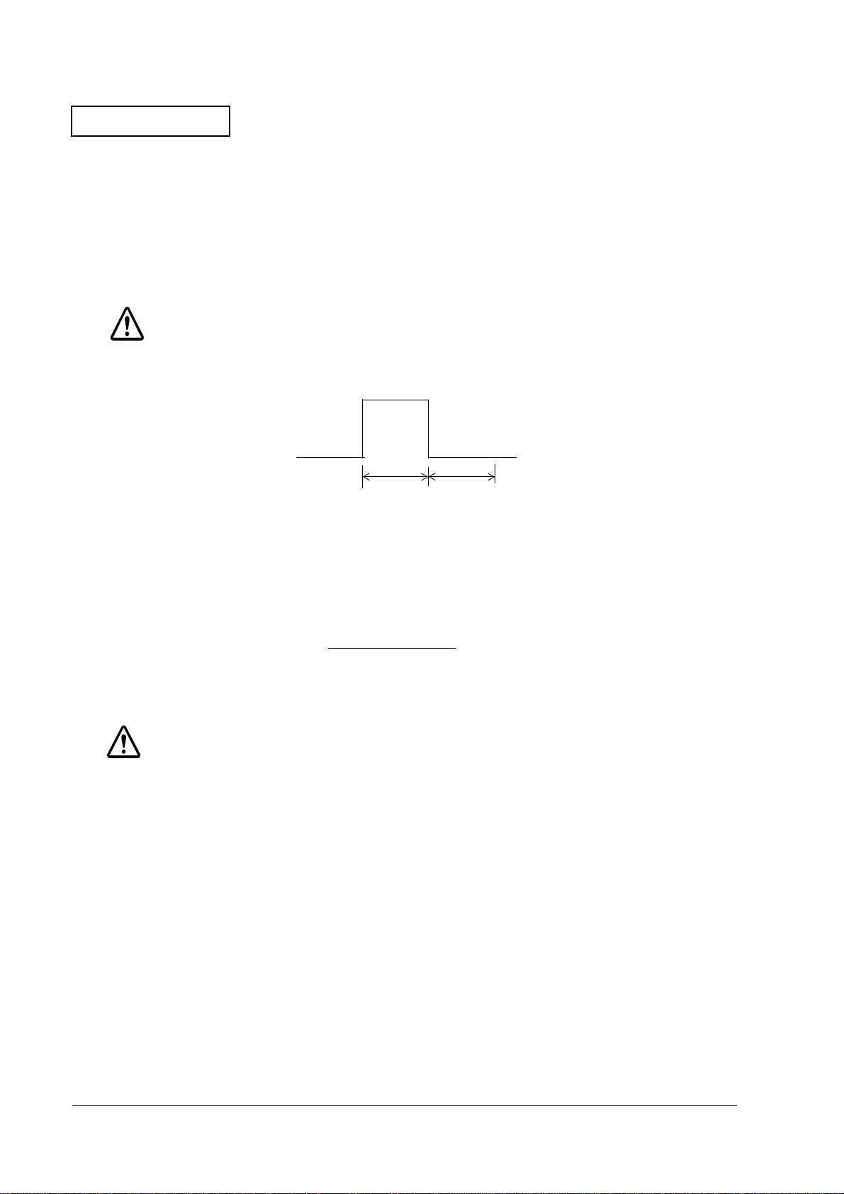
Drawer kick-out drive signal
Output signal: Voltage = Approximately 24 VDC
Current = 1 A or less
Output waveform: Outputs the waveforms in Figure 1-8 to pins
2 and 5 of the connector. t1 (ON time) and t2
(OFF time) are specified by
CAUTION:
To avoid overcurrent, resistance of the drawer kick-out solenoid must be 24 Ω or more.
t
1 x 2 ms
Figure 1-9 Drawer kick-out drive signal output waveform
t
2 x 2 ms
ESC p
.
NOTES:
❏
Two driver transistors cannot be energized simultaneously.
❏
The drawer drive duty must be as shown below:
ON time
(ON time + OFF time)
❏
Be sure to use the printer power supply (connector pin 4) for the drawer power source.
CAUTION:
≤
0.2
Do not connect a telephone line to the drawer kick-out connector; otherwise the printer
and the telephone line may be damaged.
1-12 Features and General Specifications Rev. B

Confidential
Interface
RS-232 Serial Interface
TM-U200 Series (Type B) Service Manual
Data transmission:
Synchronization:
Handshaking:
Signal levels:
Serial (compatible with RS-232)
Asynchronous
DTR/DSR or XON/XOFF control
MARK = -3 to -15 V: Logic 1/OFF
SPACE = +3 to +15 V: Logic 0/ON
Baud rates:
Data word length:
Parity settings:
Stop bits:
Connector:
NOTES:
❏
Handshaking, data word length, baud rate, and parity depend on DIP switch settings.
❏
Data transmitted from the printer has 1 stop bit (fixed).
4800, 9600 bps
7 or 8 bits
None, even, odd
1 or more
Female D-SUB 25-pin connector or equivalent
Rev. B Features and General Specifications 1-13
Confidential
Interface Connector Pin Assignments
RS-232 interface connector pin assignments and functions
Pin number Signal name I/O Function
1FG—Frame ground
2 TXD O Transmit data
3 RXD I Receive data
4 RTS O Same as the DTR signal
6 DSR I This signal indicates whether the host computer can receive data. SPACE
7 SG — Signal ground
20 DTR O 1) When DTR/DSR control is selected, this signal indicates whether the printer is
indicates the host computer can receive data, and MARK indicates the host
computer cannot receive data. When DTR/DSR control is selected, the printer
transmits data after confirming this signal (except when transmitting data by
and
EOT
this signal. Changing the DIP switch setting lets this signal be used as a reset
signal for the printer. The printer is reset when the signal remains MARK for
1 ms or more.
busy. SPACE indicates the printer is ready to receive data, and MARK indicates
the printer is busy. A busy condition can be changed using DIP SW 1-8 as follows:
Printer
Off line
). When XON/XOFF control is selected, the printer does not check
GS a
1. During the period from when power is turned on
(including reset using the interface) to when the
printer is ready to receive data.
2. During self-test BUSY BUSY
3. During paper feeding using the paper FEED button. — BUSY
4. When the printer stops printing for a paper-end. — BUSY
5. When an error has occurred. — BUSY
6. When a temporary abnormality occurs in the
power supply voltage
7. When the receive buffer becomes full. (See Notes.) BUSY BUSY
DLE
DIP SW 1-8 status
ON OFF
BUSY BUSY
—BUSY
20 DTR O 2) When XON/XOFF control is selected:
25 INIT
NOTES:
❏
When the remaining space in the receive buffer is 16 bytes, the printer buffer becomes full. This status continues
until the space in the receive buffer increases to 32 bytes.
❏
The printer ignores data received when the remaining space in the receive buffer is 0 bytes.
❏
XON is not transmitted when the receive buffer is full.
This signal indicates whether the printer is correctly connected and ready to
receive data. SPACE indicates the printer is ready to receive data. The signal is
always SPACE except in the following cases:
❏
During the period after power on until the printer is ready to receive data.
❏
During self test.
I Changing DIP switch setting enables this signal to be used as a reset signal for
the printer (see the DIP switch settings in the “Buttons and Switches” section of
this chapter). The printer is reset when the signal remains SPACE for 1 ms or more.
1-14 Features and General Specifications Rev. B

Confidential
TM-U200 Series (Type B) Service Manual
Switching between on line and off line
The printer does not have an on-line/off-line button. It goes off line under the following
conditions:
❏
Between the time when power is turned on (including reset using the interface) and when
the printer is ready to receive data.
❏
During the self-test.
❏
During paper feeding using the paper FEED button.
❏
Between the time when the printer stops printing for a paper-end and when the on-line
recovery wait time finishes after loading paper (if an empty paper supply is detected by
either the paper roll end detector or the paper roll near-end detector with a printing halt
feature enabled for low paper by
❏
When an error has occurred.
ESC c 4
).
XON/XOFF transmission timing
When XON/XOFF control is selected, the printer transmits XON or XOFF signals as follows.
Printer status
XON
transmission
XOFF
transmission
(*1)XON is not transmitted when the receive buffer is full.
(*2)XOFF is not transmitted when the receive buffer is full.
The XON code is 11H and the XOFF code is 13H.
NOTE:
• When the printer goes on line after turning power on or after
reset using the interface.
• When the receive buffer is released from the buffer full state.
• When the printer switches from off line to on line (*1).
• When the printer recovers from an error through a command.
• During an error condition.
• When the receive buffer becomes full (*2).
DIP SW 1-8 status
ON OFF
Transmission
Transmission
----
----
Transmission
Transmission
----
Transmission
Transmission
Transmission
Transmission
Transmission
Transmission
Transmission
Rev. B Features and General Specifications 1-15

Confidential
Serial interface connection example
Host
Printer
TXD
DSR
CTS
RXD
DTR
FG
SG
NOTES:
❏
Set handshaking so that transmitted data can be received.
❏
Transmit data to the printer after turning on the power and initializing the printer.
RXD
DTR
RTS
TXD
DSR
FG
SG
RS-485 Serial Interface (option)
Refer to the Appendix for details.
IEEE 1284 Parallel Interface
Complies with the standard described in the IEEE 1284 specification by the Institute of Electrical
and Electronic Engineers, Inc.
Specification
Data transmission: 8-bit parallel
Synchronization: Externally supplied STROBE
Handshaking: ACK
and BUSY signals
signals
Signal levels: TTL-compatible
Connector: 57RE-40360-830B (DDK) or equivalent (IEEE 1284 Type B)
Reverse communication
(Printer to host): Nibble or byte mode
Reverse Mode (Data Transmission from Printer to Host)
Status data transmission from the printer to the host occurs in nibble or byte mode. These modes
allow data transmission from the asynchronous printer under control of the host. Data
transmissions in nibble mode are made via the existing control lines in units of four bits (a
nibble). In byte mode, data transmissions proceed by making the eight-bit data lines
bidirectional. Both modes fail to proceed concurrently in compatibility mode, causing half
duplex transmission. The IEEE 1284 nibble/byte modes are under development in draft form
and may be subject to change.
1-16 Features and General Specifications Rev. B

Confidential
TM-U200 Series (Type B) Service Manual
Interface Connector Pin Assignments
IEEE 1284 interface connector pin assignments and functions
Pin number Source Compatibility Mode Nibble Mode Byte Mode
1 Host Strobe
2 Host/Ptr Data0 (LSB) Data0 (LSB) Data0 (LSB)
3 Host/Ptr Data1 Data1 Data1
4 Host/Ptr Data2 Data2 Data2
5 Host/Ptr Data3 Data3 Data3
6 Host/Ptr Data4 Data4 Data4
7 Host/Ptr Data5 Data5 Data5
8 Host/Ptr Data6 Data6 Data6
9 Host/Ptr Data7 (MSB) Data7 (MSB) Data7 (MSB)
10 Printer Ack
11 Printer Busy PtrBusy/Data3,7 PtrBusy
12 Printer PError AckDataReq/
13 Printer Select Xflag/Data1,5 Xflag
14 Hostr AutoFd
15 NC ND ND
16 GND GND GND
17 FG FG FG
18 Printer Logic-H Logic-H Logic-H
19-30 GND GND GND
31 Host Init
32 Printer Fault DataAvail/Data0, 4 DataAvail
33 GND ND ND
34 Printer DK_STATUS ND ND
35 Printer +5V ND ND
36 Host SelectIn
Host Clk Host Clk
PtrClk PtrClk
AckDataReq
Data2,6
HostBusy HostBusy
Init Init
1284-Active 1284-Active
NOTES:
❏
Overscored signal names are LOW active signals.
❏
If a host does not provide for the signal lines listed above, two-way communication fails.
❏
For interfacing, signal lines must use twisted pair cables with the return sides connected to signal ground level.
❏
Interfacing conditions must all be based on the TTL level to meet the characteristics described below. In
addition, both the rise and fall time of each signal must be 0.5 ms or less.
❏
Data transmission must not ignore the ACK or BUSY signal. An attempt to transmit data with either the ACK or
BUSY signal ignored can cause lost data. (Data transmissions to the printer must be made after verifying the ACK
signal or while the BUSY signal is at a LOW level.)
❏
Interface cables should be as short in length as possible.
NC: Not Connected
ND: Not Defined
Rev. B Features and General Specifications 1-17

Confidential
Reception of status from the printer through the bidirectional parallel interface
In bidirectional parallel interface operation, printer status transmission is available using the
two-way communication facility of the IEEE 1284-compatible nibble/byte modes. In this case,
unlike in RS-232 serial interface operation, real-time interruptions from the printer to the host
are disabled, and so you must pay attention to the following.
❏
The maximum capacity of the printer’s internal buffer is 100 bytes (except ASB status).
Status signals exceeding this capacity are discarded. To prevent possible loss of status, the
host must be ready for data reception (Reverse Mode).
❏
When ASB is used, the host is preferably in the wait state for data reception (Reverse Idle
Mode). When this state is not available, the host enters Reverse Mode to continually monitor
data presence.
❏
When ASB is used, preference is given to ASB status for transmission over other status
signals. Any accumulated ASB status signals left for transmission from the last to the newest
ASB status transmissions are transmitted together at one time as one ASB status showing the
presence of change, followed by the latest ASB status.
Example: In the normal (wait) state, the ASB status is configured as follows:
First Status Second Status Third Status Fourth Status
0001 0000 0000 0000 0000 0000 0000 0000
In a sequence of operations including near end detection and the paper FEED button being
pressed and released, the following pieces of data are accumulated.
First Status Second Status Third Status Fourth Status
➀
➁
➂
0001 0000 0000 0000 0000 0011 0000 0000 Near end
detection.
0101 1000 0000 0000 0000 0011 0000 0000 Paper FEED
button is
pressed.
0001 0000 0000 0000 0000 0011 0000 0000 Paper FEED
button is
released.
When ASB status is received following this, a total of eight (8) bytes of ASB will be transmitted
+➁+
➀+➁+➂
➂
)
).
First Status Second Status Third Status Fourth Status
0101 1000 0000 0000 0000 0011 0000 0000
0001 0000 0000 0000 0000 0011 0000 0000
as follows: Accumulated ASB (
Accumulated ASB (
+ First Status Second Status Third Status Fourth Status
The latest ASB (➂)
Fourth Status
➀
1-18 Features and General Specifications Rev. B
 Loading...