

Page 1
nualck™ Excella® E-24 Shaker
EN) manual
New Brunswick
Shaker
Operating manual
™
Excella® E-24
Page 2

Copyright
Copyright © 2014 Eppendorf AG, Hamburg. No part of this publication may be reproduced without the
prior permission of the copyright owner.
The company reserves the right to change information in this document without notice. Updates to
information in this document reflect our commitment to continuing product development and
improvement.
Trademarks
New Brunswick and the New Brunswick Logo™ are trademarks of Eppendorf AG, Germany.
®
Excella
Trademarks are not marked in all cases with ™ or
is a registered trademark of Eppendorf, Inc., USA.
®
in this manual.
Eppendorf has attempted to identify the ownership of all trademarks from public records. Any omissions or
errors are unintentional.
M1352-0051-A/022014
Page 3

Table of contents
™
New Brunswick
Excella® E-24 Shaker
English (EN)
Table of contents
1 Operating instructions . . . . . . . . . . . . . . . . . . . . . . . . . . . . . . . . . . . . . . . . . . . . . . . . . . . . . . . . . . . . . . 5
1.1 Using this manual . . . . . . . . . . . . . . . . . . . . . . . . . . . . . . . . . . . . . . . . . . . . . . . . . . . . . . . . . . . . . 5
1.2 Danger symbols and danger levels . . . . . . . . . . . . . . . . . . . . . . . . . . . . . . . . . . . . . . . . . . . . . . . . 5
1.2.1 Hazard symbols . . . . . . . . . . . . . . . . . . . . . . . . . . . . . . . . . . . . . . . . . . . . . . . . . . . . . . . . 5
1.2.2 Degrees of danger . . . . . . . . . . . . . . . . . . . . . . . . . . . . . . . . . . . . . . . . . . . . . . . . . . . . . . 5
1.3 Symbols used . . . . . . . . . . . . . . . . . . . . . . . . . . . . . . . . . . . . . . . . . . . . . . . . . . . . . . . . . . . . . . . . 5
1.4 Abbreviations used . . . . . . . . . . . . . . . . . . . . . . . . . . . . . . . . . . . . . . . . . . . . . . . . . . . . . . . . . . . . 6
2 Product description . . . . . . . . . . . . . . . . . . . . . . . . . . . . . . . . . . . . . . . . . . . . . . . . . . . . . . . . . . . . . . . . 7
2.1 Main illustration . . . . . . . . . . . . . . . . . . . . . . . . . . . . . . . . . . . . . . . . . . . . . . . . . . . . . . . . . . . . . . 7
2.2 Inspection of boxes . . . . . . . . . . . . . . . . . . . . . . . . . . . . . . . . . . . . . . . . . . . . . . . . . . . . . . . . . . . . 8
2.3 Features. . . . . . . . . . . . . . . . . . . . . . . . . . . . . . . . . . . . . . . . . . . . . . . . . . . . . . . . . . . . . . . . . . . . . 8
2.3.1 Operating modes . . . . . . . . . . . . . . . . . . . . . . . . . . . . . . . . . . . . . . . . . . . . . . . . . . . . . . . 8
2.3.2 Visible/audible user alarms . . . . . . . . . . . . . . . . . . . . . . . . . . . . . . . . . . . . . . . . . . . . . . . 8
2.3.3 Data logging . . . . . . . . . . . . . . . . . . . . . . . . . . . . . . . . . . . . . . . . . . . . . . . . . . . . . . . . . . 9
2.3.4 Setpoint retention . . . . . . . . . . . . . . . . . . . . . . . . . . . . . . . . . . . . . . . . . . . . . . . . . . . . . . 9
2.3.5 Automatic restart. . . . . . . . . . . . . . . . . . . . . . . . . . . . . . . . . . . . . . . . . . . . . . . . . . . . . . . 9
2.3.6 Drive interrupt . . . . . . . . . . . . . . . . . . . . . . . . . . . . . . . . . . . . . . . . . . . . . . . . . . . . . . . . . 9
3
3 Safety. . . . . . . . . . . . . . . . . . . . . . . . . . . . . . . . . . . . . . . . . . . . . . . . . . . . . . . . . . . . . . . . . . . . . . . . . . . 11
3.1 Intended use . . . . . . . . . . . . . . . . . . . . . . . . . . . . . . . . . . . . . . . . . . . . . . . . . . . . . . . . . . . . . . . . 11
3.2 Information on product liability . . . . . . . . . . . . . . . . . . . . . . . . . . . . . . . . . . . . . . . . . . . . . . . . . 11
3.3 Warnings for intended use . . . . . . . . . . . . . . . . . . . . . . . . . . . . . . . . . . . . . . . . . . . . . . . . . . . . . 11
3.3.1 Personal injury and damage to device . . . . . . . . . . . . . . . . . . . . . . . . . . . . . . . . . . . . . 12
4 Installation . . . . . . . . . . . . . . . . . . . . . . . . . . . . . . . . . . . . . . . . . . . . . . . . . . . . . . . . . . . . . . . . . . . . . . 13
4.1 Selecting the location . . . . . . . . . . . . . . . . . . . . . . . . . . . . . . . . . . . . . . . . . . . . . . . . . . . . . . . . . 13
4.2 Unpacking the device . . . . . . . . . . . . . . . . . . . . . . . . . . . . . . . . . . . . . . . . . . . . . . . . . . . . . . . . . 13
4.3 Utility requirements . . . . . . . . . . . . . . . . . . . . . . . . . . . . . . . . . . . . . . . . . . . . . . . . . . . . . . . . . . 13
4.4 Installation of platform . . . . . . . . . . . . . . . . . . . . . . . . . . . . . . . . . . . . . . . . . . . . . . . . . . . . . . . . 14
4.5 Flask clamp installation. . . . . . . . . . . . . . . . . . . . . . . . . . . . . . . . . . . . . . . . . . . . . . . . . . . . . . . . 15
4.6 Electrical connections . . . . . . . . . . . . . . . . . . . . . . . . . . . . . . . . . . . . . . . . . . . . . . . . . . . . . . . . . 16
5 Operation. . . . . . . . . . . . . . . . . . . . . . . . . . . . . . . . . . . . . . . . . . . . . . . . . . . . . . . . . . . . . . . . . . . . . . . . 17
5.1 Start/stop. . . . . . . . . . . . . . . . . . . . . . . . . . . . . . . . . . . . . . . . . . . . . . . . . . . . . . . . . . . . . . . . . . . 17
5.2 Continuous (untimed) run. . . . . . . . . . . . . . . . . . . . . . . . . . . . . . . . . . . . . . . . . . . . . . . . . . . . . . 17
5.3 Check setpoint. . . . . . . . . . . . . . . . . . . . . . . . . . . . . . . . . . . . . . . . . . . . . . . . . . . . . . . . . . . . . . . 17
5.4 Timed functions . . . . . . . . . . . . . . . . . . . . . . . . . . . . . . . . . . . . . . . . . . . . . . . . . . . . . . . . . . . . . 18
5.4.1 Setting the timer . . . . . . . . . . . . . . . . . . . . . . . . . . . . . . . . . . . . . . . . . . . . . . . . . . . . . . 18
5.4.2 If the shaker is stopped: . . . . . . . . . . . . . . . . . . . . . . . . . . . . . . . . . . . . . . . . . . . . . . . . 18
5.5 Alarm functions. . . . . . . . . . . . . . . . . . . . . . . . . . . . . . . . . . . . . . . . . . . . . . . . . . . . . . . . . . . . . . 19
5.5.1 Deactivating . . . . . . . . . . . . . . . . . . . . . . . . . . . . . . . . . . . . . . . . . . . . . . . . . . . . . . . . . 19
5.5.2 Reactivating. . . . . . . . . . . . . . . . . . . . . . . . . . . . . . . . . . . . . . . . . . . . . . . . . . . . . . . . . . 19
5.6 Temperature setpoint . . . . . . . . . . . . . . . . . . . . . . . . . . . . . . . . . . . . . . . . . . . . . . . . . . . . . . . . . 19
5.7 Temperature offset calibration . . . . . . . . . . . . . . . . . . . . . . . . . . . . . . . . . . . . . . . . . . . . . . . . . . 19
5.8 Factory Calibration . . . . . . . . . . . . . . . . . . . . . . . . . . . . . . . . . . . . . . . . . . . . . . . . . . . . . . . . . . . 20
5.9 Speed calibration . . . . . . . . . . . . . . . . . . . . . . . . . . . . . . . . . . . . . . . . . . . . . . . . . . . . . . . . . . . . 20
5.9.1 Calibration adjustments . . . . . . . . . . . . . . . . . . . . . . . . . . . . . . . . . . . . . . . . . . . . . . . . 20
Page 4

Table of contents
™
New Brunswick
4
Excella® E-24 Shaker
English (EN)
5.10 Power failure . . . . . . . . . . . . . . . . . . . . . . . . . . . . . . . . . . . . . . . . . . . . . . . . . . . . . . . . . . . . . . . . 21
6 Operating controls and function . . . . . . . . . . . . . . . . . . . . . . . . . . . . . . . . . . . . . . . . . . . . . . . . . . . . . 23
6.1 Control panel. . . . . . . . . . . . . . . . . . . . . . . . . . . . . . . . . . . . . . . . . . . . . . . . . . . . . . . . . . . . . . . . 23
6.1.1 User interface keys . . . . . . . . . . . . . . . . . . . . . . . . . . . . . . . . . . . . . . . . . . . . . . . . . . . . 23
6.1.2 Status indicators . . . . . . . . . . . . . . . . . . . . . . . . . . . . . . . . . . . . . . . . . . . . . . . . . . . . . . 24
6.1.3 LED display . . . . . . . . . . . . . . . . . . . . . . . . . . . . . . . . . . . . . . . . . . . . . . . . . . . . . . . . . . 24
6.1.4 Function indicators . . . . . . . . . . . . . . . . . . . . . . . . . . . . . . . . . . . . . . . . . . . . . . . . . . . . 25
7 Troubleshooting . . . . . . . . . . . . . . . . . . . . . . . . . . . . . . . . . . . . . . . . . . . . . . . . . . . . . . . . . . . . . . . . . . 27
8 Maintenance . . . . . . . . . . . . . . . . . . . . . . . . . . . . . . . . . . . . . . . . . . . . . . . . . . . . . . . . . . . . . . . . . . . . . 29
8.1 Routine maintenance . . . . . . . . . . . . . . . . . . . . . . . . . . . . . . . . . . . . . . . . . . . . . . . . . . . . . . . . . 29
8.2 Opening the service compartment . . . . . . . . . . . . . . . . . . . . . . . . . . . . . . . . . . . . . . . . . . . . . . . 29
8.2.1 Fuse replacement . . . . . . . . . . . . . . . . . . . . . . . . . . . . . . . . . . . . . . . . . . . . . . . . . . . . . 29
8.3 Cleaning . . . . . . . . . . . . . . . . . . . . . . . . . . . . . . . . . . . . . . . . . . . . . . . . . . . . . . . . . . . . . . . . . . . 30
8.4 Disinfection/decontamination . . . . . . . . . . . . . . . . . . . . . . . . . . . . . . . . . . . . . . . . . . . . . . . . . . . 30
9 Transport, storage and disposal . . . . . . . . . . . . . . . . . . . . . . . . . . . . . . . . . . . . . . . . . . . . . . . . . . . . . 31
9.1 Disposal. . . . . . . . . . . . . . . . . . . . . . . . . . . . . . . . . . . . . . . . . . . . . . . . . . . . . . . . . . . . . . . . . . . . 31
10 Technical data. . . . . . . . . . . . . . . . . . . . . . . . . . . . . . . . . . . . . . . . . . . . . . . . . . . . . . . . . . . . . . . . . . . . 33
10.1 Weight/dimensions . . . . . . . . . . . . . . . . . . . . . . . . . . . . . . . . . . . . . . . . . . . . . . . . . . . . . . . . . . . 33
10.1.1 Device dimensions . . . . . . . . . . . . . . . . . . . . . . . . . . . . . . . . . . . . . . . . . . . . . . . . . . . . 33
10.1.2 Platform dimensions . . . . . . . . . . . . . . . . . . . . . . . . . . . . . . . . . . . . . . . . . . . . . . . . . . . 33
10.1.3 Chamber dimensions . . . . . . . . . . . . . . . . . . . . . . . . . . . . . . . . . . . . . . . . . . . . . . . . . . 33
10.1.4 Required space/footprint. . . . . . . . . . . . . . . . . . . . . . . . . . . . . . . . . . . . . . . . . . . . . . . . 33
10.2 Application parameters . . . . . . . . . . . . . . . . . . . . . . . . . . . . . . . . . . . . . . . . . . . . . . . . . . . . . . . . 33
10.2.1 Speed. . . . . . . . . . . . . . . . . . . . . . . . . . . . . . . . . . . . . . . . . . . . . . . . . . . . . . . . . . . . . . . 33
10.2.2 Capacity. . . . . . . . . . . . . . . . . . . . . . . . . . . . . . . . . . . . . . . . . . . . . . . . . . . . . . . . . . . . . 34
10.2.3 Temperature . . . . . . . . . . . . . . . . . . . . . . . . . . . . . . . . . . . . . . . . . . . . . . . . . . . . . . . . . 34
10.3 Power supply. . . . . . . . . . . . . . . . . . . . . . . . . . . . . . . . . . . . . . . . . . . . . . . . . . . . . . . . . . . . . . . . 34
11 Ordering information . . . . . . . . . . . . . . . . . . . . . . . . . . . . . . . . . . . . . . . . . . . . . . . . . . . . . . . . . . . . . . 35
11.1 Accessories . . . . . . . . . . . . . . . . . . . . . . . . . . . . . . . . . . . . . . . . . . . . . . . . . . . . . . . . . . . . . . . . . 35
12 Declaration of conformity . . . . . . . . . . . . . . . . . . . . . . . . . . . . . . . . . . . . . . . . . . . . . . . . . . . . . . . . . . 39
Index . . . . . . . . . . . . . . . . . . . . . . . . . . . . . . . . . . . . . . . . . . . . . . . . . . . . . . . . . . . . . . . . . . . . . . . . . . . 41
Page 5
Operating instructions
™
New Brunswick
Excella® E-24 Shaker
English (EN)
1 Operating instructions
1.1 Using this manual
Carefully read this operating manual before using the device for the first time.
Also observe the operating manual enclosed with the accessories.
The operating manual should be considered as part of the product and stored in a location that is easily
accessible.
When passing the device on to third parties, be sure to include this operating manual.
If this manual is lost, please request another one. The current version can be found on our website http:/
/www.eppendorf.com.
1.2 Danger symbols and danger levels
1.2.1 Hazard symbols
5
Hazard point Material damage
Electric shock
1.2.2 Degrees of danger
The following degree levels are used in safety messages throughout this manual. Acquaint yourself with
each item and the potential risk if you disregard the safety message.
DANGER Will lead to severe injuries or death.
WARNING May lead to severe injuries or death.
CAUTION May lead to light to moderate injuries.
NOTICE May lead to material damage.
1.3 Symbols used
Example Meaning
You are requested to perform an action.
1.
2.
• List.
Perform these actions in the sequence described.
References useful information.
Page 6

Operating instructions
New Brunswick
6
English (EN)
™
Excella® E-24 Shaker
1.4 Abbreviations used
kWh
Kilowatt hours
PI
Proportional/Integral
PPE
Personal Protective Equipment
RMA
Return Material Authorization
rpm
Revolutions Per Minute
UEL
Upper Explosion Limit
VA
Volt Amps
VAC
Voltage in Alternating Current
Page 7

2 Product description
2.1 Main illustration
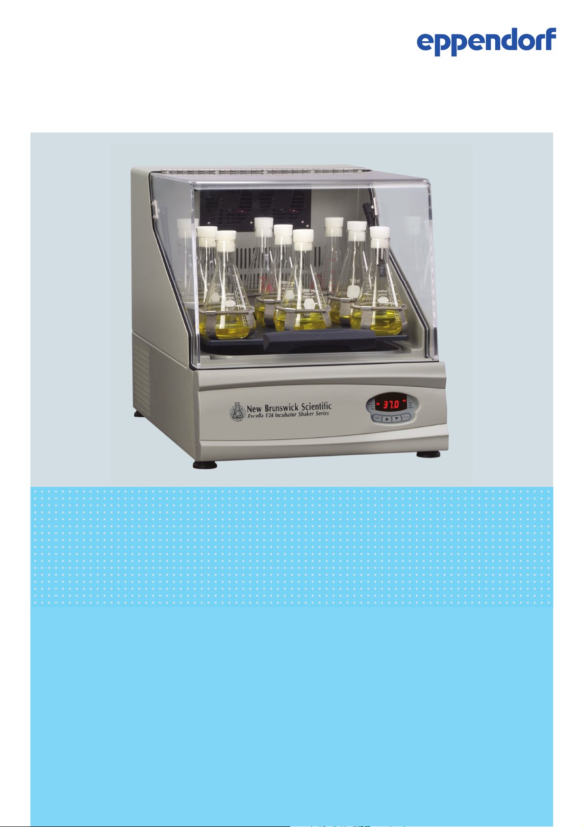
Abb. 2-1: New Brunswick™ Excella® E-24 incubator shaker
New Brunswick
Product description
™
Excella® E-24 Shaker
English (EN)
7
2
1
3
Fig. 2-1: New Brunswick™ Excella® E-24 incubator shaker
1 Lid handle
2 User interface
3 On/off switch
Page 8

Product description
New Brunswick
8
English (EN)
™
Excella® E-24 Shaker
2.2 Inspection of boxes
After you have received your order, inspect the boxes carefully for any damage that may have occurred
during shipping. Report any damage to the carrier and to your local Eppendorf distributor immediately.
2.3 Features
The Excella E-24 Benchtop Incubator Shakers uses a unicentric counter-balanced drive mechanism. It
provides horizontal plane rotary motion in a 1.91 cm (¾ in) diameter circular orbit. A Proportional/Integral
(PI) microprocessor controls the speed and temperature over the entire range.
The E-24 operates from 7 °C above ambient to 60 °C. This range depends on relative humidity and other
ambient factors. Ambient temperature is measured one meter from the front of the unit.
Erlenmeyer flasks, 2.8-liter Fernbach flasks, and a wide variety of tubes and plates can be accommodated
using New Brunswick shaker accessories.
A wide variety of platforms can be used with the Excella E-24:
• Universal platforms are the most flexible, providing hole patterns for flask clamps, test tube racks and
other accessories.
• Dedicated platforms are supplied with flask clamps attached; they are designed solely and expressly for
this purpose.
• Test tube racks, microplate holders, and test tube rack holders are also available (a universal platform is
needed for all test tube racks and holders).
For further information on these accessories (see Accessories on p. 35).
2.3.1 Operating modes
The E-24 may be operated in the following modes:
• Continuously: at a set speed and temperature, until user intervention.
• In a timed mode: run at a set speed, time and temperature for a period of up to 99.9 hours, after which
the incubator shaker automatically shuts off, while the temperature is maintained at its setpoint.
2.3.2 Visible/audible user alarms
The E-24 is equipped with visual and audible alarms for the following conditions:
• The end of a timed run
• Deviations from speed setpoint (5 minutes after lid is closed)
• Deviations from temperature setpoint (5 minutes after lid is closed)
• Power failure
• Lid open
Page 9

Product description
™
New Brunswick
Excella® E-24 Shaker
English (EN)
2.3.3 Data logging
RS-232 connection provided for data logging.
2.3.4 Setpoint retention
All setpoints and operating status are retained in non-volatile memory.
2.3.5 Automatic restart
Automatic restart after power is restored, indicated by flashing display.
2.3.6 Drive interrupt
Drive interrupt shuts off power to the incubator shaker when the lid opens. Acceleration/deceleration
circuit prevents sudden starts and stops, minimizing both splashing and mechanical damage.
9
Page 10

10
Product description
™
New Brunswick
Excella® E-24 Shaker
English (EN)
Page 11

Safety
English (EN)
New Brunswick
™
Excella® E-24 Shaker
3 Safety
3.1 Intended use
The New Brunswick Excella E-24 is half incubator and half biological shaker, combining the best features
of New Brunswick incubators and shakers into one versatile instrument. It provides gentle shaking and
accurate control of temperature, enabling growth of hybridomas, insect cultures, mammalian and stem
cells as well as both aerobic and anaerobic bacteria and yeast.
The New Brunswick Excella E-24 was designed for controlled incubation and shaking of biological
samples. Do not use any heat-generating device inside the chamber.
CAUTION! Lack of safety due to incorrect accessories or spare parts
Accessories and spare parts that are not recommended by Eppendorf compromise the safety,
function and precision of the device. Eppendorf cannot be held liable or accept any liability for
damage resulting from the use of non-recommended accessories and spare parts.
11
Only use accessories and original spare parts recommended by Eppendorf.
3.2 Information on product liability
In the following cases, the designated protection of the device may be compromised.
The liability for the function of the device passes to the operator if:
• The device is not used in accordance with this operating manual.
• The device is used outside of the range of application described in the succeding chapters.
• The device is used with accessories or consumables that were not approved by Eppendorf.
• Service or maintenance is completed on the device by people who are not authorized by Eppendorf.
• The owner has made unauthorized modifications to the device.
3.3 Warnings for intended use
Before using the incubator shaker, read the operating manual and observe the following general safety
instructions.
Page 12

12
Safety
New Brunswick
English (EN)
™
Excella® E-24 Shaker
3.3.1 Personal injury and damage to device
WARNING! Health risk due to poisonous, radioactive or aggressive chemicals
Observe the national regulations for handling these substances as well as the material
safety data sheets and manufacturer's application notes.
Wear personal protective equipment (PPE).
WARNING! Burns due to hot metal on the device and hot pistons
Only touch the device and pistons when wearing protective gloves.
WARNING! Risk of crushing fingers with lid
Do not reach between the lid and device, or into the lid locking mechanism, when opening
and closing the device.
Always fully open the lid so it cannot fall and close.
CAUTION! Risk to health due to lifting heavy loads
Only lift the device with another person or using a suitable aid.
Make sure to use a transport aid for transportation over long distances.
NOTICE! Damage due to overheating
Do not place the device close to sources of heat (e.g., radiator, drying cabinet).
Do not expose the device to direct sunlight.
Ensure there is adequate distance to the wall and adjacent devices, on all sides of the
device, in order to guarantee unobstructed air circulation.
Page 13

™
New Brunswick
Excella® E-24 Shaker
4 Installation
4.1 Selecting the location
NOTICE! Damage due to overheating
Do not place the device close to sources of heat (e.g., radiator, drying cabinet).
Do not expose the device to direct sunlight.
Ensure there is adequate distance to the wall and adjacent devices, on all sides of the
device, in order to guarantee unobstructed air circulation.
Select the location according to the following criteria:
• Suitable mains power connection according to the ID plate
• Stable, even and resonance-free base
• Well ventilated area and no direct sunlight to prevent additional temperature increases
• Ambient conditions of 10 °C to 35 °C, 20 % to 80 % non condensing
• Able to accommodate 200 lb
Installation
13
English (EN)
4.2 Unpacking the device
Keep the packing material and transport securing device for later transport or storage.
1. Remove the packing material.
2. Remove the transport securing device.
3. Use the details included in the scope of delivery to check that the delivery is complete.
4. Check all parts for damage in transit. Contact Eppendorf Service if parts are missing or transport
damage is present.
4.3 Utility requirements
The following utility requirements are needed for operation:
Utility Requirement
Electricity • 230 V, 60 Hz, 1500 VA maximum
In all cases, voltage variations must not exceed ±10 %.
Page 14
14
Installation
™
New Brunswick
Excella® E-24 Shaker
English (EN)
4.4 Installation of platform
A platform must be installed prior to use.
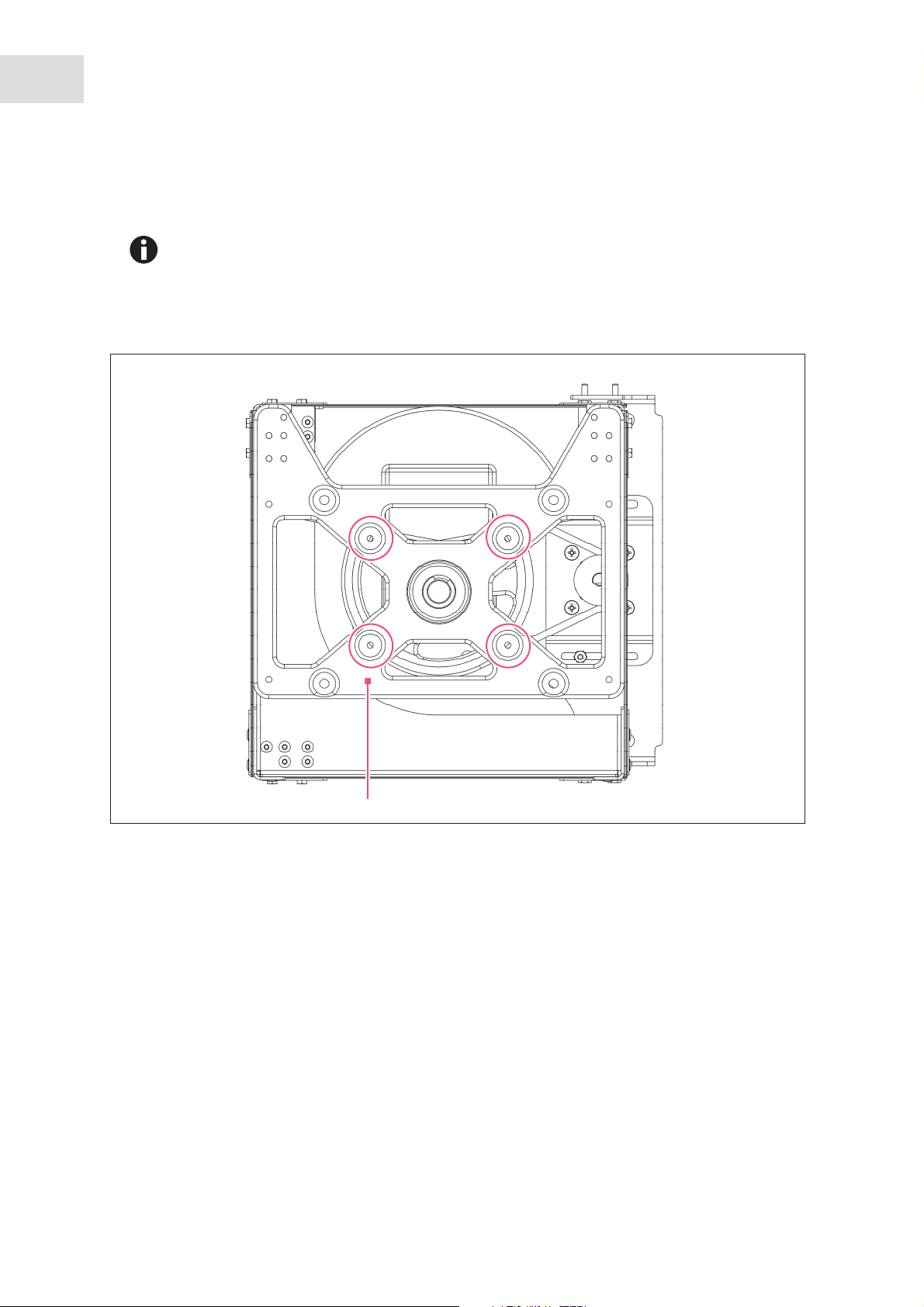
The shaker is shipped with 4 Allen head platform screws (circled in red, (see Fig. 4-1 on p. 14)) installed in
the 4 bearing housing uprights. The screws must be removed before a platform can be installed.
Abb. 4-1: Platform screw locations
1
Fig. 4-1: Platform screw locations
1 Subplatform
1. Remove the 2 small plastic straps that secure the bearing housing in place for shipping.
2. Using the 7/32 in hex key provided, remove the 4 Allen head platform screws (circled in red, (see
Fig. 4-1 on p. 14)) from the subplatform.
Save the screws for later use.
3. Place the selected platform on the subplatform. Align the mounting holes of the platform with the
platform screw locations in the subplatform.
4. Insert the 4 Allen head platform screws removed in step 2. Tighten them with the 7/32 in hex key to
secure the platform.
Page 15

™
New Brunswick
Excella® E-24 Shaker
English (EN)
4.5 Flask clamp installation
Flask clamps purchased for use with the platform require installation. Clamps are installed by securing the
base of the clamp to the platform with the correct type and number of screws. All clamps are shipped
complete with hardware.
The Excella E-24 platform requires 10-24 × 5/16 in Phillips-head screws (which are supplied)
to fasten flask clamps.
Clamps for 2.8 L and 2 L flasks are shipped with an additional girdle to keep the flasks in place. The girdle
is an assembly of springs and sections of rubber tubing. One girdle is already in place on the clamp, the
other is packed separately.
To install these double girdle clamps:
1. Place the clamp on the platform, aligning its mounting holes with holes on the platform.
2. Secure the clamp in place using the flat Phillips head screws provided (#S2116-3051, 10-24 x 5/16 in).
Installation
15
3 different types of screws are shipped with the clamps. To identify the proper screws (see
Fig. 4-2 on p. 15).
3. The first girdle is delivered in place. Insert an empty flask into the clamp.
4. Make sure the sections of tubing are located between the clamp legs, and roll the first girdle down the
legs of the clamp as far as it can go.
The tubing sections will rest against the platform. The springs will be under the clamp base.
5. Place the second girdle around the upper portion of clamp body.
6. Make sure that the spring sections of the second girdle rest against the clamp legs, and that the rubber
sections sit against the flask (in between the clamp legs (see Fig. 4-3 on p. 16)).
Abb. 4-2: Clamp fastener
Fig. 4-2: Clamp fastener
One-liter and larger flask clamps are fastened with 5 screws.
Page 16

16
Installation
™
New Brunswick
Excella® E-24 Shaker
English (EN)
Abb. 4-3: Double girdle clamp installation
4
3
Fig. 4-3: Double girdle clamp installation
1
2
1 Upper girdle with girdle tubes
2 Clamp body (legs and base)
The upper girdle secures the flask within the clamp, and the bottom girdle keeps the flask
from spinning.
4.6 Electrical connections
NOTICE! Risk of material damage
An earthed/grounded electrical outlet is necessary for the safe operation of this
instrument.
CAUTION! Risk of electrical hazard
Before making electrical connections, be sure to check the following list.
3 Lower girdle with girdle tubes
4 Clamp mounting holes
Quantity: 5
1. If you have not already done so, check that the voltage and frequency of your incubator shaker are
compatible with your mains/electric supply.
2. Remove the caution label from the rear of the unit.
3. Set the on/off switch to the off position.
ONLY THEN:
4. Plug the mains/power cord into an earthed/grounded electrical outlet.
Page 17

™
New Brunswick
Excella® E-24 Shaker
English (EN)
5 Operation
5.1 Start/stop
The shaker will not incubate if the lid is open.
To initially start the shaker:
1. Turn the on/off switch to the on position.
During start-up, the LED display will indicate the model of your shaker.
2. Press the START/STOP key on the keypad to start or stop operation of the platform.
When the shaker begins to operate, the LED display will track the speed as it accelerates to the last
setpoint entered.
Operation
17
5.2 Continuous (untimed) run
1. Press SELECT until the RPM indicator is illuminated.
2. If the display indicates that the shaker is OFF, press the START/STOP key.
3. Press either the or key to enter SET mode.
The SET indicator will illuminate.
4. Set the speed by using the or key until the desired setpoint is displayed.
Holding the or key for more than 0.5 seconds causes the speed setpoint to change.
Should this occur, resetting will be necessary.
The setpoint may be changed during a run without stopping the shaker by following Steps 2 –
4 above. During speed changes, a visual alarm (flashing RPM indicator) will flash, and an
audible alarm will sound until the speed returns to within 5 rpm of the setpoint.
5.3 Check setpoint
1. Press SELECT until the desired indicator is illuminated.
2. Briefly press either the or key to enter the SET mode and display the current setpoint.
Holding the or key for more than 0.5 seconds causes the speed setpoint to change.
Should this occur, resetting will be necessary.
Page 18

18
Operation
New Brunswick
English (EN)
™
Excella® E-24 Shaker
5.4 Timed functions
The shaker may be programmed to automatically stop after a preset time period of 0.1 to 99.9 hours. There
must be power to the shaker in order to set the timer, although a timed run can be initiated while the shaker
is either stopped or operating.
5.4.1 Setting the timer
To set the timer:
1. Press the SELECT key until the HRS indicator is illuminated.
2. Press either the or key to enter the SET mode and set the desired run time, between 0.1 and 99.9
hours.
If the shaker is stopped, (see If the shaker is stopped: on p. 18). If the shaker is already running
continue to Step 3.
3. Press the START/STOP key.
The shaker will stop and the display will read OFF.
4. Press the START/STOP key again.
The TIME indicator will light and the shaker will start the timed run.
To cancel the timer without stopping the shaker:
Repeat steps 1 and 2.
Immediately press the START/STOP key.
The TIME indicator will stop flashing and the display will read OFF.
5.4.2 If the shaker is stopped:
1. Follow steps 1 and 2, (see Setting the timer on p. 18)
2. Press the START/STOP key. The shaker will start in untimed mode.
3. Press the START/STOP key again. The shaker will stop and the display will read OFF.
4. Press the START/STOP key a third time; the TIME indicator will light and the shaker will start the timed
run.
To disable the visual alarm (flashing TIME indicator):
Press the SELECT key and change to any other function
Page 19

Operation
English (EN)
New Brunswick
™
Excella® E-24 Shaker
5.5 Alarm functions
In addition to visual alarm, the Excella E-24 has an audible alarm that is activated at predetermined times.
It can be deactivated by using the MUTE function (see Deactivating on p. 19).
5.5.1 Deactivating
1. Press the SELECT key until the MUTE indicator illuminates.
2. Press the or key to display ON, then press the SELECT key.
5.5.2 Reactivating
To reactivate the audible alarm:
1. Press the SELECT key until the MUTE indicator illuminates.
19
2. Press the or key to display OFF, then press the SELECT key.
5.6 Temperature setpoint
Press the SELECT key until the function °C indicator illuminates. The temperature can be set from 5 °C
above ambient temperature to 60 °C (non-refrigerated units) or from 7 °C to 60 °C (refrigerated units).
Increasing or decreasing the setpoint is accomplished with the or key.
During operation, if the temperature of the chamber is more than 1.0 °C higher or lower than the
temperature setpoint, an alarm is triggered. This alarm consists of a flashing °C indicator and audible beep.
The alarm will automatically deactivate as the incubator shaker achieves the set temperature.
5.7 Temperature offset calibration
The temperature probe and the temperature controller are calibrated together at the factory. The
temperature probe measures the temperature of the air at the probe’s location, near the heat exchanger
return vent. The controller uses the probe input to adjust air temperature, up or down, to match the
temperature setpoint.
Depending on various conditions within the chamber (flask placement and size, heat produced by growing
organisms, heat losses due to liquid evaporation from flasks, etc.), the display temperature may differ from
temperatures within the flasks themselves.
Page 20

20
Operation
New Brunswick
English (EN)
If you wish to have the temperature display (indicated temperature) match the temperature at a given point
or match the average of a series of points within the chamber (actual Temperature), proceed as follows:
1. Let the unit equilibrate at or near the desired temperature. Record the indicated temperature.
2. Record the actual temperature.
3. Calculate the temperature correction value.
Actual Temperature – Indicated Temperature = Temperature Correction Value
4. Press the SELECT key until the function °C indicator illuminates.
5. Simultaneously press the or keys. The display will indicate CAL.
6. Using the and keys, enter the Temperature Correction Value calculated in Step 3.
7. Simultaneously press the and to save the Temperature Correction Value to memory.
™
Excella® E-24 Shaker
The °C light will pulse rapidly to indicate it is not operating in the factory default mode.
5.8 Factory Calibration
To return to the factory calibration:
1. Press the SELECT key until the function °C indicator illuminates.
2. Simultaneously press the and keys. The display will indicate CAL.
3. Using the or key, set the Temperature Correction Value to zero.
4. Simultaneously press the and keys. The rapid pulsing of the °C indicator will stop.
5.9 Speed calibration
To calibrate the shaking speed:
1. Set the shaker to a speed that can easily be measured. If you are using a strobe, minimum speed should
be 250 rpm.
2. Compare the reading on the display to the measured reading.
5.9.1 Calibration adjustments
If an adjustment is needed:
1. Press the SELECT key until the RPM indicator light illuminates.
2. Press the and keys simultaneously. The display will indicate CAL.
3. Press either the or keys to change the displayed value to match the measured speed.
4. Press the and keys simultaneously to save the adjustment.
5. Turn the shaker off using the on/off switch, then turn it back on.
Page 21

Operation
English (EN)
New Brunswick
™
Excella® E-24 Shaker
5.10 Power failure
In the event of a power failure, the Excella E-24 is equipped with an automatic restart function.
If the shaker was in operation prior to the power interruption, when power is restored the shaker will begin
to operate at its last entered setpoint. The LED display will flash and the audible alarm will sound,
indicating that a power failure has occurred. Press any key to stop the flashing in the display and the
audible alarm.
21
Page 22

22
Operation
New Brunswick
English (EN)
™
Excella® E-24 Shaker
Page 23

Operating controls and function
™
New Brunswick
Excella® E-24 Shaker
English (EN)
6 Operating controls and function
6.1 Control panel
The control panel consists of the status indicators, LED display, function indicators, and the user interface
keys.
Abb. 6-1: Control panel
1
2
3
4
23
Fig. 6-1: Control panel
1 Status indicators
2 LED display
3 Function indicators
4 User interface keys
6.1.1 User interface keys
Key Description
START/STOP • Starts and stops the shaker
• Starts and stops the timer when a timed run is
desired.
SELECT • Used to change the displayed parameter
or
• Used to adjust the setpoint of a displayed
parameter up or down
• They also allow the user to enter the SET mode
for setpoint changes
Page 24

24
Operating controls and function
New Brunswick
English (EN)
™
Excella® E-24 Shaker
6.1.2 Status indicators
4 status indicator lights are located to the left of the LED display.
Indicator Meaning Description
SET Shaker is in SET mode • Setpoints are displayed and
can be altered
• Activated by pressing the
SELECT key or the (up) or
(down) keys
POWER Power failure • Illuminates and blinks during
power up or if power is
interrupted during a run
• Press the SELECT key and
change to another function to
turn off this indicator
HEAT Heater is on • Illuminate to indicate that the
heater is on
TIME Timer is in operation • Shaker can be programmed to
run for a preset time from 0.1
to 99.9 hours
• Can be disengaged without
stopping an ongoing run
6.1.3 LED display
The digital display on the control panel is a three-digit LED display. During normal operation, the display
will indicate:
• Shaker status (On/Off)
• Shaking speed
• Chamber temperature
• Setpoints
• Hours remaining (in a timed run)
• Lid open (LID)
Page 25

Operating controls and function
™
New Brunswick
Excella® E-24 Shaker
English (EN)
6.1.4 Function indicators
4 function indicator lights are located to the right of the LED DISPLAY. They indicate the current
parameter(s) being displayed.
Indicator Meaning Description
°C Interior chamber temperature • When in SET mode, can be set
between 7 °C and 60 °C using
the or keys
• Indexes at 0.1 °C increments
unless the or key is
pressed for 4 seconds, after
which it indexes more rapidly
RPM Revolutions per minute
HRS Time remaining in a timed run • Can be set from 0.1 to 99.9
MUTE Audible alarm mute • Controlled by the SELECT key
• When in SET mode, use the
or key to change the speed
• Indexes at 1 RPM increments
unless the or key is
pressed for 4 seconds, after
which it indexes more rapidly
hours using the or keys
• Indexes at 0.1 hour increments
unless the or key is
pressed for 4 seconds, after
which it indexes more rapidly
• When activated, the audible
alarm is muted, and remains
so until is is reactivated
• If MUTE is ctivated when the
shaker is turned off, it will
remain active when the unit is
powered on
• Press the SELECT key until the
MUTE indicator illuminates;
press the or key to
display ON or OFF as desired,
then press SELECT.
25
Page 26

26
Operating controls and function
™
New Brunswick
Excella® E-24 Shaker
English (EN)
Page 27

New Brunswick
7 Troubleshooting
Symptoms Possible causes Solutions
Shaker does not run • Power cord is not plugged in
and/or power switch is off
• Lid is open, Lid is indicated on
the display
• Recently replaced fuse may
not be seated properly
• On/off switch is not working
• Defective main board
• Defective display controller
board
• Jammed shaking mechanism
• Defective motor
• Drive belt out of alignment or
worn
Shaker runs slowly and/or no
speed indication
Shaker does not run at set speed • Shaker is overloaded and/or
Operating noise • Load out of balance
Incubator does not reach set
temperature
• Incorrect speed calibration
• Defective main board
• Defective motor
• Drive belt out of alignment or
worn
you are using baffled flasks
• Defective motor
• Drive belt is out of alignment
or worn
• Loose component(s) in
platform, subplatform and/or
drive assembly
• Heater fuse blown
• Ambient temperature too high
or too low
• Compressor over-pressure
switch activated
• Defective heater
• Incorrect temperature
indication
Plug in power cord to working
electrical outlet
Turn on the power switch
Open and reclose the lid firmly
Reinstall the fuse carefully
Call for service
Recalibrate shaking speed (see
Speed calibration on p. 20)
Call for service
Remove some contents and
balance load
Call for service
Unload all contents and reload
Call for service
Replace (see Fuse replacement
on p. 29)
Cool or heat the room as
needed
Call for service
(see Tab. on p. 28)
Troubleshooting
™
Excella® E-24 Shaker
English (EN)
27
Page 28

28
Troubleshooting
™
New Brunswick
Excella® E-24 Shaker
English (EN)
Symptoms Possible causes Solutions
Incorrect temperature indication • Defective RTD assembly
Call for service
• Defective main board
Page 29

Maintenance
English (EN)
New Brunswick
™
Excella® E-24 Shaker
8 Maintenance
8.1 Routine maintenance
No routine maintenance schedule is required for the E-24.
Clean the incubator shaker occasionally using a cloth with conventional household (non-abrasive) cleaner.
To ensure proper air flow in and around the incubator shaker, vacuum or sweep the area around the
incubator shaker to remove dust and other debris.
8.2 Opening the service compartment
WARNING!
29
Before opening the service compartment, always turn off the shaker and disconnect the
power cord from the power supply.
The service compartment contains the shaker’s electronic and temperature control components. Normally,
this compartment should be accessed by authorized service technicians only. You may, from time to time,
need to remove the access panel in order to replace fuses.
8.2.1 Fuse replacement
WARNING!
When replacing fuses, always turn off the shaker and disconnect the power cord from the
power supply.
The user can replace one fuse on the E-24, located behind the front bezel panel (on the PC board). To
access the fuse:
1. Turn the power off and unplug the shaker.
2. Open the front cover.
3. Remove the 4 fastners that hold the front panel in place.
Set them aside for the reuse.
4. The fuse is located on the PC board located on the right side of the base weldment.
5. Access the fuse by using a coin or a blade screwdriver to turn and release the spring-loaded cap.
6. Replace it with a new one of the same type and rating.
Fuse holder number Function Type Rating
F1 Heater Slo Blo 8 A 8.0 A
Page 30

30
Maintenance
New Brunswick
English (EN)
™
Excella® E-24 Shaker
8.3 Cleaning
NOTICE! Risk of equipment damage
Use of abrasive or corrosive compounds may damage the incubator shaker.
Do not use abrasive or corrosive compounds to clean the incubator shaker.
1. Routinely clean the exterior of the incubator shaker by wiping it over with a soft cloth, moistened with
soapy water.
2. Rinse the soap from the cloth in clean water, and wipe the exterior surfaces again.
If Biohazard decontamination is necessary, (see Disinfection/decontamination on p. 30).
8.4 Disinfection/decontamination
WARNING! Risk of potential harm to personnel
It is the responsibility of the user to carry out appropriate decontamination procedures if
hazardous material is spilled on or inside the equipment. Before using any cleaning or
decontamination method other than those suggested by the manufacturer, users contact
Eppendorf to ensure that the proposed method would not damage the equipment.
CAUTION! Risk of potential harm to personnel
As a routine precaution, wear protective gloves.
Be sure to adequately ventilate the work area as you disinfect, to avoid the formation of
potentially explosive alcohol vapors.
Commercially available household bleach solutions, when diluted at a 1:10 ratio, are effective in routine
decontamination of the incubator shaker. The method for decontaminating a spill depends upon the nature
of the spill.
1. Switch the shaker off and unplug it from the mains/power supply.
2. Spills involving fresh cultures or samples known to have low concentrations of biomass should be
flooded with decontamination solution and soaked for 5 minutes before cleanup.
3. Spills involving samples with high concentrations of biomass, or involving organic matter, or occurring
in areas warmer than room ambient temperature, should be exposed to decontamination solution for at
least one hour before cleanup.
Page 31

Transport, storage and disposal
New Brunswick
™
Excella® E-24 Shaker
English (EN)
9 Transport, storage and disposal
9.1 Disposal
In case the product is to be disposed of, the relevant legal regulations are to be observed.
Information on the disposal of electrical and electronic devices in the European Community:
Within the European Community, the disposal of electrical devices is regulated by national regulations
based on EU Directive 2012/19/EU pertaining to waste electrical and electronic equipment (WEEE).
According to these regulations, any devices supplied after August 13, 2005, in the business-to-business
sphere, to which this product is assigned, may no longer be disposed of in municipal or domestic waste. To
document this, they have been marked with the following identification:
31
Because disposal regulations may differ from one country to another within the EU, please contact your
supplier if necessary.
In Germany, this is mandatory from March 23, 2006. From this date, the manufacturer has to offer a
suitable method of return for all devices supplied after August 13, 2005. For all devices supplied before
August 13, 2005, the last user is responsible for the correct disposal.
Page 32

32
Transport, storage and disposal
™
New Brunswick
Excella® E-24 Shaker
English (EN)
Page 33

New Brunswick
10 Technical data
10.1 Weight/dimensions
10.1.1 Device dimensions
Width (External) 56 cm (22 in)
Height (External) 61 cm (24 in)
Height (with lid open) 101.9 cm (40 in)
Depth (External) 76 cm (30 in)
Weight 60 kg (133 lb)
10.1.2 Platform dimensions
Width 46 cm (18 in)
Depth 46 cm (18 in)
™
Technical data
Excella® E-24 Shaker
English (EN)
33
10.1.3 Chamber dimensions
Width 51.7 cm (20 3/8 in)
Height 34.4 cm (13 9/16 in)
Depth 53.3 cm (21 in)
10.1.4 Required space/footprint
Width 68.6 cm (27 in)
Height 106.7 cm (42 in)
Depth 83.8 cm (33 in)
10.2 Application parameters
10.2.1 Speed
50 rpm – 400 rpm
Control accuracy ±1 rpm
Use of baffled flasks will significantly reduce maximum speed for any incubator shaker. We
may be able to improve this maximum speed by using an alternative motor pulley. Contact
your Eppendorf representative for more information.
Page 34

34
Technical data
New Brunswick
English (EN)
™
Excella® E-24 Shaker
10.2.2 Capacity
Heater Long-life, low-watt density
resistance-type heater with high
temperature thermostat
10.2.3 Temperature
Range +7 °C above ambient temperature to
60 °C
Accuracy ±0.1 °C at 37 °C
Ambient operating environment 10 to 35 °C, 20 to 80 % relative
humidity, non-condensing
10.3 Power supply
E-24 main/power supply
230 V, 60 Hz 800 VA
Page 35

Ordering information
™
New Brunswick
Excella® E-24 Shaker
English (EN)
11 Ordering information
11.1 Accessories
Universal platforms have multiple holes, enabling you to mount an assortment of flask clamps or other
accessories on a single platform.
When only one size flask will be used on the shaker (i.e. 250 mL flasks), dedicated platforms come with
flask clamps already mounted. Dedicated platforms generally will hold a greater number of flasks than the
universal platform, but do not offer the versatility.
The capacities shown represent the maximum number of flasks in a given size that will fit on the platform in
a balanced pattern.
Dedicated platform Universal platform
10 mL - 109
25 mL - 64
50 mL 64 45
125 mL 34 21
M1194-9904
250 mL 25 18
M1194-9905
500 mL 16 14
M1194-9906
1 L 9 8
M1194-9907
2 L 5 5
M1194-9908
2.8 L 4 4
M1194-9932
4 L _ -
5 L - -
6 L - 2
Large test tube rack - 4
Medium test tube rack - 5
Small test tube rack - 5
Microplate rack (stack) - 8
Microplate rack (1 layer) - 2
35
Page 36

36
Ordering information
™
New Brunswick
Excella® E-24 Shaker
English (EN)
Platforms Part number
Universal platform M1250-9902
Utility carrier with cushioned crossbars M1194-9909
Utility tray with non-skid rubber surface M1194-9910
Sticky pad platform M1250-9903
Flask clamps Part number
10 ml Erlenmeyer Flask ACE-10S
25 ml Erlenmeyer Flask M1190-9004
50 ml Erlenmeyer Flask M1190-9000
125 ml Erlenmeyer Flask M1190-9001
250 ml Erlenmeyer Flask M1190-9002
500 ml Erlenmeyer Flask M1190-9003
1 L Erlenmeyer Flask ACE-1000S
2 L Erlenmeyer Flask ACE-2000S
2.8 L Fernbach Flask ACSB-2800S
Racks and trays Part number Platform
capacity
Adjustable angle Test Tube Rack for
tubes 8 – 11 mm diameter
80 tube capacity M1289-0110 4
60 tube capacity M1289-0010 5
48 tube capacity M1289-0001 5
Adjustable angle Test Tube Rack for
tubes 12 – 15 mm diameter
60 tube capacity M1289-0200 4
44 tube capacity M1289-0020 5
34 tube capacity M1289-0002 5
Adjustable angle Test Tube Rack for
tubes 15 – 18 mm diameter
42 tube capacity M1289-0300 4
31 tube capacity M1289-0030 5
24 tube capacity M1289-0003 5
Adjustable angle Test Tube Rack for
tubes 18 – 21 mm diameter
30 tube capacity M1289-0400 4
23 tube capacity M1289-0040 5
18 tube capacity M1289-0004 5
Adjustable angle Test Tube Rack for
tubes 22 – 26 mm diameter
22 tube capacity M1289-0500 4
16 tube capacity M1289-0050 5
13 tube capacity M1289-0005 5
Page 37

Ordering information
™
New Brunswick
Excella® E-24 Shaker
English (EN)
Racks and trays Part number Platform
capacity
Adjustable angle Test Tube Rack for
tubes 26 – 30 mm diameter
20 tube capacity M1289-0600 4
16 tube capacity M1289-0060 5
12 tube capacity M1289-0006 5
Microplate holder rack (stacked) 3 deep well or 9 standard M1289-0700 8
Microplate holder rack (single layer) 5 deep well or standard TTR-221 2
Angled Test Tube Rack Holder* for
NA TTR-210 2
user-supplied test tube racks that are
10 - 13 mm (4 – 5 in) wide and up to
38 mm (15 in) long
Angled Test Tube Rack Spacer Bar*
NA TTR-215 NA
for use with TTR-210 to accommodate
test tubes racks that are less than 13
mm (5 in) wide.
37
*Universal platform required
Page 38

38
Ordering information
™
New Brunswick
Excella® E-24 Shaker
English (EN)
Page 39

12 Declaration of conformity
Declaration of conformity
New Brunswick
™
Excella® E-24 Shaker
English (EN)
39
Page 40

40
Declaration of conformity
™
New Brunswick
Excella® E-24 Shaker
English (EN)
Page 41

New Brunswick
™
Excella® E-24 Shaker
Index
English (EN)
41
Index
A
Accessories
Flask clamps.....................................................36
Flasks ...............................................................35
Platforms..........................................................35
Racks and trays ................................................36
Actual temperature................................................20
Alarm functions .....................................................19
Audible alarm ........................................................19
Auto restart function .............................................21
C
Caution, explanation of ...........................................5
Control panel .........................................................23
Copyright.................................................................2
N
Notice, explanation of............................................. 5
P
Platform ................................................................14
Power failure......................................................... 21
Product liability..................................................... 11
R
Requirements, utility............................................. 13
S
Speed calibration .................................................. 20
Status indicators ................................................... 24
Symbols used.......................................................... 5
T
D
Danger, explanation of ............................................5
Dimensions............................................................33
Disposal .................................................................31
F
Factory calibration.................................................20
Flask clamp............................................................15
Function indicators................................................25
H
Hazard symbols .......................................................5
I
Indicated temperature...........................................20
M
Temperature offset calibration.............................. 19
Temperature setpoint............................................ 19
Trademarks............................................................. 2
U
Using this manual ................................................... 5
Utility requirements.............................................. 13
W
Warning, explanation of .........................................5
Weight................................................................... 33
Manual conventions ................................................5
Mute alarm ............................................................19
Page 42

Page 43

Page 44

Evaluate your manual
Give us your feedback.
www.eppendorf.com/manualfeedback
Your local distributor: www.eppendorf.com/contact
Eppendorf AG · 22331 Hamburg · Germany
eppendorf@eppendorf.com · www.eppendorf.com
 Loading...