

Page 1

Operating manual
—
Innova® U360 -86 C Freezers
see
on p.Fig.Tab.p
.
Op
l
erating manua
September 22, 2011
New Brunswick -86 °C Freezers
Innova® U360
Operating manual
M1288-0070
Revision F
Page 2

Copyright
Copyright© 2011 New Brunswick Scientific Co., Inc., USA. No part of this publication may be reproduced without the prior
permission of the copyright owner.
New Brunswick Scientific reserves the right to change information in this document without notice. Updates to information
in this document reflect our commitment to continuing product development and improvement.
Trademarks
Eppendorf® is a registered trademark of Eppendorf AG, Germany.
BioCommand
®
is a registered trademark of New Brunswick Scientific Co., Inc., USA.
Innova® is a registered trademark of New Brunswick Scientific Co., Inc., USA.
New Brunswick™ and the New Brunswick Logo™ are trademarks of Eppendorf AG, Germany.
Trademarks are not marked in all cases with ™ or
®
in this manual.
New Brunswick Scientific has attempted to identify the ownership of all trademarks from public records. Any omissions or
errors are unintentional.
September 29, 2011
Revision F
M1288-0070
Page 3

Innova® U360 -86 °C Freezers — Operating manual
Table of contents
1 Table of contents
1
1 Operating instructions . . . . . . . . . . . . . . . . . . . . . . . . . . . . . . . . . . . . . . . . . . . . . . . . . . . . . . . . . . . . . . . . . . . . . . . 7
1.1 Using this manual . . . . . . . . . . . . . . . . . . . . . . . . . . . . . . . . . . . . . . . . . . . . . . . . . . . . . . . . . . . . . . . . . . . . . . . 7
1.2 Danger symbols and danger levels . . . . . . . . . . . . . . . . . . . . . . . . . . . . . . . . . . . . . . . . . . . . . . . . . . . . . . . . . 7
1.2.1 Hazard symbols . . . . . . . . . . . . . . . . . . . . . . . . . . . . . . . . . . . . . . . . . . . . . . . . . . . . . . . . . . . . . . . . . 7
1.2.2 Degrees of danger . . . . . . . . . . . . . . . . . . . . . . . . . . . . . . . . . . . . . . . . . . . . . . . . . . . . . . . . . . . . . . . 7
1.3 Symbols used . . . . . . . . . . . . . . . . . . . . . . . . . . . . . . . . . . . . . . . . . . . . . . . . . . . . . . . . . . . . . . . . . . . . . . . . . . 7
1.4 Abbreviations used . . . . . . . . . . . . . . . . . . . . . . . . . . . . . . . . . . . . . . . . . . . . . . . . . . . . . . . . . . . . . . . . . . . . . . 8
2 Safety . . . . . . . . . . . . . . . . . . . . . . . . . . . . . . . . . . . . . . . . . . . . . . . . . . . . . . . . . . . . . . . . . . . . . . . . . . . . . . . . . . . . . 9
2.1 Intended use. . . . . . . . . . . . . . . . . . . . . . . . . . . . . . . . . . . . . . . . . . . . . . . . . . . . . . . . . . . . . . . . . . . . . . . . . . . 9
2.2 Warnings for intended use . . . . . . . . . . . . . . . . . . . . . . . . . . . . . . . . . . . . . . . . . . . . . . . . . . . . . . . . . . . . . . . . 9
2.2.1 Manual conventions used . . . . . . . . . . . . . . . . . . . . . . . . . . . . . . . . . . . . . . . . . . . . . . . . . . . . . . . . . . 9
2.2.2 Health and safety at work act 1974. . . . . . . . . . . . . . . . . . . . . . . . . . . . . . . . . . . . . . . . . . . . . . . . . . . 9
3 Product description. . . . . . . . . . . . . . . . . . . . . . . . . . . . . . . . . . . . . . . . . . . . . . . . . . . . . . . . . . . . . . . . . . . . . . . . . 10
3.1 Main illustration. . . . . . . . . . . . . . . . . . . . . . . . . . . . . . . . . . . . . . . . . . . . . . . . . . . . . . . . . . . . . . . . . . . . . . . . 10
3.2 Delivery package . . . . . . . . . . . . . . . . . . . . . . . . . . . . . . . . . . . . . . . . . . . . . . . . . . . . . . . . . . . . . . . . . . . . . . 10
3.2.1 Inspection of boxes . . . . . . . . . . . . . . . . . . . . . . . . . . . . . . . . . . . . . . . . . . . . . . . . . . . . . . . . . . . . . . 10
3.2.2 Packing list verification . . . . . . . . . . . . . . . . . . . . . . . . . . . . . . . . . . . . . . . . . . . . . . . . . . . . . . . . . . . 11
3.3 Product versions. . . . . . . . . . . . . . . . . . . . . . . . . . . . . . . . . . . . . . . . . . . . . . . . . . . . . . . . . . . . . . . . . . . . . . . 11
3.3.1 Introduction . . . . . . . . . . . . . . . . . . . . . . . . . . . . . . . . . . . . . . . . . . . . . . . . . . . . . . . . . . . . . . . . . . . . 11
3.4 Features . . . . . . . . . . . . . . . . . . . . . . . . . . . . . . . . . . . . . . . . . . . . . . . . . . . . . . . . . . . . . . . . . . . . . . . . . . . . . 11
3.5 Warranty . . . . . . . . . . . . . . . . . . . . . . . . . . . . . . . . . . . . . . . . . . . . . . . . . . . . . . . . . . . . . . . . . . . . . . . . . . . . . 12
3.5.1 Warranty registration . . . . . . . . . . . . . . . . . . . . . . . . . . . . . . . . . . . . . . . . . . . . . . . . . . . . . . . . . . . . . 12
3.5.2 Extended warranty option . . . . . . . . . . . . . . . . . . . . . . . . . . . . . . . . . . . . . . . . . . . . . . . . . . . . . . . . . 12
Table of contents
4 Installation . . . . . . . . . . . . . . . . . . . . . . . . . . . . . . . . . . . . . . . . . . . . . . . . . . . . . . . . . . . . . . . . . . . . . . . . . . . . . . . . 13
4.1 Preparing installation . . . . . . . . . . . . . . . . . . . . . . . . . . . . . . . . . . . . . . . . . . . . . . . . . . . . . . . . . . . . . . . . . . . 13
4.1.1 Setup guide. . . . . . . . . . . . . . . . . . . . . . . . . . . . . . . . . . . . . . . . . . . . . . . . . . . . . . . . . . . . . . . . . . . . 13
4.2 Selecting the location . . . . . . . . . . . . . . . . . . . . . . . . . . . . . . . . . . . . . . . . . . . . . . . . . . . . . . . . . . . . . . . . . . . 13
4.3 Installing the shelves . . . . . . . . . . . . . . . . . . . . . . . . . . . . . . . . . . . . . . . . . . . . . . . . . . . . . . . . . . . . . . . . . . . 13
4.4 Installing the voltage stabilizer . . . . . . . . . . . . . . . . . . . . . . . . . . . . . . . . . . . . . . . . . . . . . . . . . . . . . . . . . . . . 14
4.5 Lockable freezer handle . . . . . . . . . . . . . . . . . . . . . . . . . . . . . . . . . . . . . . . . . . . . . . . . . . . . . . . . . . . . . . . . . 14
5 Operating controls and function . . . . . . . . . . . . . . . . . . . . . . . . . . . . . . . . . . . . . . . . . . . . . . . . . . . . . . . . . . . . . . 16
5.1 Controls and function . . . . . . . . . . . . . . . . . . . . . . . . . . . . . . . . . . . . . . . . . . . . . . . . . . . . . . . . . . . . . . . . . . . 16
5.1.1 Menu system. . . . . . . . . . . . . . . . . . . . . . . . . . . . . . . . . . . . . . . . . . . . . . . . . . . . . . . . . . . . . . . . . . . 17
6 Operation . . . . . . . . . . . . . . . . . . . . . . . . . . . . . . . . . . . . . . . . . . . . . . . . . . . . . . . . . . . . . . . . . . . . . . . . . . . . . . . . . 18
6.1 Getting started . . . . . . . . . . . . . . . . . . . . . . . . . . . . . . . . . . . . . . . . . . . . . . . . . . . . . . . . . . . . . . . . . . . . . . . . 18
6.1.1 Plug in . . . . . . . . . . . . . . . . . . . . . . . . . . . . . . . . . . . . . . . . . . . . . . . . . . . . . . . . . . . . . . . . . . . . . . . . 18
6.1.2 Turning the freezer On/Off . . . . . . . . . . . . . . . . . . . . . . . . . . . . . . . . . . . . . . . . . . . . . . . . . . . . . . . . 18
6.1.3 Alarm/battery activation . . . . . . . . . . . . . . . . . . . . . . . . . . . . . . . . . . . . . . . . . . . . . . . . . . . . . . . . . . 19
6.1.4 Remote alarm . . . . . . . . . . . . . . . . . . . . . . . . . . . . . . . . . . . . . . . . . . . . . . . . . . . . . . . . . . . . . . . . . . 19
6.1.5 Vacuum effect . . . . . . . . . . . . . . . . . . . . . . . . . . . . . . . . . . . . . . . . . . . . . . . . . . . . . . . . . . . . . . . . . . 20
6.2 Operating temperature and alarm setpoints . . . . . . . . . . . . . . . . . . . . . . . . . . . . . . . . . . . . . . . . . . . . . . . . . . 20
6.2.1 Setting operating temperature and alarm setpoints . . . . . . . . . . . . . . . . . . . . . . . . . . . . . . . . . . . . . 20
6.2.2 Checking temperature settings . . . . . . . . . . . . . . . . . . . . . . . . . . . . . . . . . . . . . . . . . . . . . . . . . . . . . 20
6.2.3 Setting time and date . . . . . . . . . . . . . . . . . . . . . . . . . . . . . . . . . . . . . . . . . . . . . . . . . . . . . . . . . . . . 21
6.3 Alarm functions and system sensors . . . . . . . . . . . . . . . . . . . . . . . . . . . . . . . . . . . . . . . . . . . . . . . . . . . . . . . 21
6.3.1 Modifying alarm functions . . . . . . . . . . . . . . . . . . . . . . . . . . . . . . . . . . . . . . . . . . . . . . . . . . . . . . . . . 21
3
Page 4

1
Table of contents
Innova® U360 -86 °C Freezers — Operating manual
6.3.2 Temperature alarm delay . . . . . . . . . . . . . . . . . . . . . . . . . . . . . . . . . . . . . . . . . . . . . . . . . . . . . . . . . 22
6.3.3 Door open alarm delay . . . . . . . . . . . . . . . . . . . . . . . . . . . . . . . . . . . . . . . . . . . . . . . . . . . . . . . . . . . 22
6.3.4 Audible alarm mute . . . . . . . . . . . . . . . . . . . . . . . . . . . . . . . . . . . . . . . . . . . . . . . . . . . . . . . . . . . . . . 22
6.3.5 Alarm socket delay . . . . . . . . . . . . . . . . . . . . . . . . . . . . . . . . . . . . . . . . . . . . . . . . . . . . . . . . . . . . . . 22
6.3.6 Alarm mute and acknowledgement. . . . . . . . . . . . . . . . . . . . . . . . . . . . . . . . . . . . . . . . . . . . . . . . . . 23
6.3.7 Setpoint and security control. . . . . . . . . . . . . . . . . . . . . . . . . . . . . . . . . . . . . . . . . . . . . . . . . . . . . . . 23
6.3.8 Setting the temperature offset. . . . . . . . . . . . . . . . . . . . . . . . . . . . . . . . . . . . . . . . . . . . . . . . . . . . . . 24
6.4 Audible alarm battery backup . . . . . . . . . . . . . . . . . . . . . . . . . . . . . . . . . . . . . . . . . . . . . . . . . . . . . . . . . . . . . 24
6.5 Alarm monitoring socket . . . . . . . . . . . . . . . . . . . . . . . . . . . . . . . . . . . . . . . . . . . . . . . . . . . . . . . . . . . . . . . . . 25
6.6 Data storage and viewing . . . . . . . . . . . . . . . . . . . . . . . . . . . . . . . . . . . . . . . . . . . . . . . . . . . . . . . . . . . . . . . . 26
6.6.1 Alarm log. . . . . . . . . . . . . . . . . . . . . . . . . . . . . . . . . . . . . . . . . . . . . . . . . . . . . . . . . . . . . . . . . . . . . . 26
6.6.2 Cabinet and ambient temperature graph . . . . . . . . . . . . . . . . . . . . . . . . . . . . . . . . . . . . . . . . . . . . . 26
6.6.3 1st and 2nd stage cycling and condenser temperature graph . . . . . . . . . . . . . . . . . . . . . . . . . . . . . 27
6.7 Diagnostics . . . . . . . . . . . . . . . . . . . . . . . . . . . . . . . . . . . . . . . . . . . . . . . . . . . . . . . . . . . . . . . . . . . . . . . . . . . 28
6.8 PS2 service data ports . . . . . . . . . . . . . . . . . . . . . . . . . . . . . . . . . . . . . . . . . . . . . . . . . . . . . . . . . . . . . . . . . . 29
6.9 Voltage stabilizer . . . . . . . . . . . . . . . . . . . . . . . . . . . . . . . . . . . . . . . . . . . . . . . . . . . . . . . . . . . . . . . . . . . . . . 29
7 Maintenance . . . . . . . . . . . . . . . . . . . . . . . . . . . . . . . . . . . . . . . . . . . . . . . . . . . . . . . . . . . . . . . . . . . . . . . . . . . . . . . 31
7.1 Cleaning . . . . . . . . . . . . . . . . . . . . . . . . . . . . . . . . . . . . . . . . . . . . . . . . . . . . . . . . . . . . . . . . . . . . . . . . . . . . . 31
7.1.1 Painted surfaces . . . . . . . . . . . . . . . . . . . . . . . . . . . . . . . . . . . . . . . . . . . . . . . . . . . . . . . . . . . . . . . . 31
7.1.2 Panels and shelves. . . . . . . . . . . . . . . . . . . . . . . . . . . . . . . . . . . . . . . . . . . . . . . . . . . . . . . . . . . . . . 31
7.1.3 Air intake grille and filter . . . . . . . . . . . . . . . . . . . . . . . . . . . . . . . . . . . . . . . . . . . . . . . . . . . . . . . . . . 31
7.1.4 Heated vent port . . . . . . . . . . . . . . . . . . . . . . . . . . . . . . . . . . . . . . . . . . . . . . . . . . . . . . . . . . . . . . . . 31
7.1.5 Door or lid seal . . . . . . . . . . . . . . . . . . . . . . . . . . . . . . . . . . . . . . . . . . . . . . . . . . . . . . . . . . . . . . . . . 32
7.2 Routine maintenance . . . . . . . . . . . . . . . . . . . . . . . . . . . . . . . . . . . . . . . . . . . . . . . . . . . . . . . . . . . . . . . . . . . 32
7.2.1 Lubrication . . . . . . . . . . . . . . . . . . . . . . . . . . . . . . . . . . . . . . . . . . . . . . . . . . . . . . . . . . . . . . . . . . . . 32
7.2.2 Defrosting . . . . . . . . . . . . . . . . . . . . . . . . . . . . . . . . . . . . . . . . . . . . . . . . . . . . . . . . . . . . . . . . . . . . . 32
7.2.3 Removing the inner doors. . . . . . . . . . . . . . . . . . . . . . . . . . . . . . . . . . . . . . . . . . . . . . . . . . . . . . . . . 32
7.2.4 Replacing the inner door. . . . . . . . . . . . . . . . . . . . . . . . . . . . . . . . . . . . . . . . . . . . . . . . . . . . . . . . . . 33
7.2.5 Electrical components. . . . . . . . . . . . . . . . . . . . . . . . . . . . . . . . . . . . . . . . . . . . . . . . . . . . . . . . . . . . 33
8 Troubleshooting. . . . . . . . . . . . . . . . . . . . . . . . . . . . . . . . . . . . . . . . . . . . . . . . . . . . . . . . . . . . . . . . . . . . . . . . . . . . 35
8.1 General errors . . . . . . . . . . . . . . . . . . . . . . . . . . . . . . . . . . . . . . . . . . . . . . . . . . . . . . . . . . . . . . . . . . . . . . . . 35
8.1.1 Safety alarms . . . . . . . . . . . . . . . . . . . . . . . . . . . . . . . . . . . . . . . . . . . . . . . . . . . . . . . . . . . . . . . . . . 35
8.1.2 Mains/power failure. . . . . . . . . . . . . . . . . . . . . . . . . . . . . . . . . . . . . . . . . . . . . . . . . . . . . . . . . . . . . . 35
8.1.3 Inner doors . . . . . . . . . . . . . . . . . . . . . . . . . . . . . . . . . . . . . . . . . . . . . . . . . . . . . . . . . . . . . . . . . . . . 35
8.2 Error messages . . . . . . . . . . . . . . . . . . . . . . . . . . . . . . . . . . . . . . . . . . . . . . . . . . . . . . . . . . . . . . . . . . . . . . . 35
9 Technical data . . . . . . . . . . . . . . . . . . . . . . . . . . . . . . . . . . . . . . . . . . . . . . . . . . . . . . . . . . . . . . . . . . . . . . . . . . . . . 38
9.1 Specifications . . . . . . . . . . . . . . . . . . . . . . . . . . . . . . . . . . . . . . . . . . . . . . . . . . . . . . . . . . . . . . . . . . . . . . . . . 38
10 Ordering Information. . . . . . . . . . . . . . . . . . . . . . . . . . . . . . . . . . . . . . . . . . . . . . . . . . . . . . . . . . . . . . . . . . . . . . . . 39
10.1 Accessories . . . . . . . . . . . . . . . . . . . . . . . . . . . . . . . . . . . . . . . . . . . . . . . . . . . . . . . . . . . . . . . . . . . . . . . . . . 39
10.1.1 A2 independent temperature monitor . . . . . . . . . . . . . . . . . . . . . . . . . . . . . . . . . . . . . . . . . . . . . . . . 39
10.1.2 Auto-dialers. . . . . . . . . . . . . . . . . . . . . . . . . . . . . . . . . . . . . . . . . . . . . . . . . . . . . . . . . . . . . . . . . . . . 39
10.1.3 Temperature probes . . . . . . . . . . . . . . . . . . . . . . . . . . . . . . . . . . . . . . . . . . . . . . . . . . . . . . . . . . . . . 39
10.1.4 Validation packages . . . . . . . . . . . . . . . . . . . . . . . . . . . . . . . . . . . . . . . . . . . . . . . . . . . . . . . . . . . . . 39
10.1.5 Padlock adapter kits . . . . . . . . . . . . . . . . . . . . . . . . . . . . . . . . . . . . . . . . . . . . . . . . . . . . . . . . . . . . . 39
10.1.6 CO
10.1.7 Inventory racking systems. . . . . . . . . . . . . . . . . . . . . . . . . . . . . . . . . . . . . . . . . . . . . . . . . . . . . . . . . 39
10.1.8 Chart recorder. . . . . . . . . . . . . . . . . . . . . . . . . . . . . . . . . . . . . . . . . . . . . . . . . . . . . . . . . . . . . . . . . . 40
10.1.9 New Brunswick BioCommand SFI datalogging software (RS-485 interface) . . . . . . . . . . . . . . . . . . 40
11 Transport, storage and disposal . . . . . . . . . . . . . . . . . . . . . . . . . . . . . . . . . . . . . . . . . . . . . . . . . . . . . . . . . . . . . . 41
11.1 Shut down. . . . . . . . . . . . . . . . . . . . . . . . . . . . . . . . . . . . . . . . . . . . . . . . . . . . . . . . . . . . . . . . . . . . . . . . . . . . 41
and LN2 back-up systems . . . . . . . . . . . . . . . . . . . . . . . . . . . . . . . . . . . . . . . . . . . . . . . . . . . . . 39
2
4
Page 5

Innova® U360 -86 °C Freezers — Operating manual
11.2 Transport . . . . . . . . . . . . . . . . . . . . . . . . . . . . . . . . . . . . . . . . . . . . . . . . . . . . . . . . . . . . . . . . . . . . . . . . . . . . 41
11.3 Disposal . . . . . . . . . . . . . . . . . . . . . . . . . . . . . . . . . . . . . . . . . . . . . . . . . . . . . . . . . . . . . . . . . . . . . . . . . . . . . 41
1
12 Certificates . . . . . . . . . . . . . . . . . . . . . . . . . . . . . . . . . . . . . . . . . . . . . . . . . . . . . . . . . . . . . . . . . . . . . . . . . . . . . . . . 42
Index . . . . . . . . . . . . . . . . . . . . . . . . . . . . . . . . . . . . . . . . . . . . . . . . . . . . . . . . . . . . . . . . . . . . . . . . . . . . . . . . . . . . . 43
Table of contents
5
Page 6

1
Innova® U360 -86 °C Freezers — Operating manual
Table of contents
6
Page 7
Innova® U360 -86 °C Freezers — Operating manual
1 Operating instructions
1 Operating instructions
1.1 Using this manual
Carefully read this operating manual before using the device for the first time.
Also observe the operating manual enclosed with the accessories.
The operating manual should be considered as part of the product and stored in a location
that is easily accessible.
When passing the device on to third parties, be sure to include this operating manual.
If this manual is lost, please request another one. The current version can be found on our
website http://www.nbsc.com
1.2 Danger symbols and danger levels
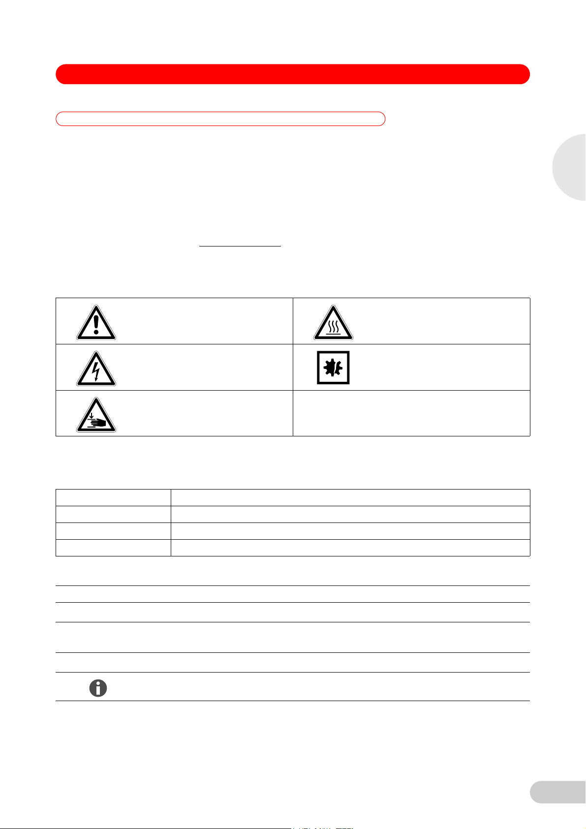
1.2.1 Hazard symbols
Hazard point Burns
Electric shock Material damage
.
1
Operating instructions
Crush
1.2.2 Degrees of danger
The following degree levels are used in safety messages throughout this manual. Acquaint
yourself with each item and the potential risk if you disregard the safety message.
DANGER Will lead to severe injuries or death.
WARNIN G May lead to severe injuries or death.
CAUTION May lead to light to moderate injuries.
NOTICE May lead to material damage.
1.3 Symbols used
Example Meaning
You are requested to perform an action.
1.
2.
Perform these actions in the sequence described.
• List.
References useful information.
7
Page 8

1
Operating instructions
Innova® U360 -86 °C Freezers — Operating manual
1.4 Abbreviations used
A Amp
CFC Chlorofluorocarbons
°C Degree Celsius
HCFC Hydrochlorofluorocarbon
HFC Hydrofluorocarbon
Hz Hertz
kg Kilogram
lb Pound
m Meter
min Minute
mm Millimeter
N/A Not applicable
rpm Revolutions per Minute (min
ULT Ultra-Low Temperature
V Volt
-1
)
8
Page 9

Innova® U360 -86 °C Freezers — Operating manual
2 Safety
2Safety
2.1 Intended use
New Brunswick Innova freezers are designed to provide precise, ultra-low temperature
environments for cold storage of scientific or medical materials. They are designed to provide
ultra-low temperature sample storage from -50 °C to -86 °C at 32 °C maximum ambient
operating temperature.
2.2 Warnings for intended use
2.2.1 Manual conventions used
Risk of material damage
This equipment must be operated as described in this manual.
NOTICE!
Please read the entire operating manual before attempting to use this equipment. If
operational guidelines are not followed, equipment damage may occur.
Risk of personal injury
Do not use this equiment in a hazardous atmosphere or with hazardous materials for which
CAUTION!
the equipment was not designed.
Please read the entire operating manual before attempting to use this equipment. If
operational guidelines are not followed, personal injury may occur.
Risk of personal injury
Crush Warning messages alert you to specific procedures or practices regarding heavy
CAUTION!
objects which, if not followed correctly, could result in serious personal injury.
Risk of personal injury
Flammable warning messages alert you to possible risks of of personal injury and equipment
WARNING!
damage: protect the system from sparks and flames.
2
Safety
2.2.2 Health and safety at work act 1974
(FOR THE UNITED KINGDOM)
New Brunswick Scientific, as manufacturers and suppliers of laboratory equipment, are obliged
under the terms of the above Act to provide our users with instructions on the safe installation,
operation and maintenance of our equipment.
Our equipment is designed to acceptable standards and does not entail any hazard if used, as
advised in the attached instructions.
The following safety precautions should be observed by all personnel using this equipment:
1. Read and understand this manual. If in doubt, contact your local New Brunswick sales office.
2. Do not remove any covers. There are no operable controls other than those referred to in this
manual. There are voltages in excess of 41.5 volts AC behind the covers.
3. Use freezer gloves at all times when loading or unloading the equipment. The temperature of
operation is such that direct contact with the cold contents or inside the equipment can burn
unprotected skin.
4. Observe good housekeeping practices, at all times keeping the equipment and the adjacent
areas clean, dry and uncluttered.
5. Should any malfunctions occur or be suspected, immediately call a qualified service engineer
to investigate.
9
Page 10

Innova® U360 -86 °C Freezers — Operating manual
3 Product description
3 Product description
3.1 Main illustration
3
Abb. 1: U360 upright freezer - sid e and front views
12
3
4
Product description
612 711 10 9 8
Fig. 1: U360 upright freezer - side and front views
1 Heated vent port 2 Door handle (lockable)
3 Control panel/display 4 Air filter (behind panel)
5 Adjustable feet 6 Voltage stabilizer (optional)
7 Chart recorder (optional) 8 PS2 connector
9 Battery switch (alarm) behind lockable panel 10 On/Off circuit breaker behind lockable panel
11 Specification plate 12 Tansport castors
5
3.2 Delivery package
3.2.1 Inspection of boxes
Inspect the boxes carefully for any damage that may have occurred during shipping. Report any
damage to the carrier and to your local New Brunswick Sales Order Department immediately.
10
Page 11

Innova® U360 -86 °C Freezers — Operating manual
3.2.2 Packing list verification
Unpack your order, saving the packing materials for possible future use. Save the operating
manual for instruction and reference. Verify against your New Brunswick packing list that you
have received the correct materials, and that nothing is missing. If any part of your order was
damaged during shipping, is missing, or fails to operate, fill out the "Customer Feedback" form,
available online at www.nbsc.com/CustomerFeedback.aspx.
Risk of material damage
Vacuum insulation panels are used in the construction of these freezers. Inspect the cabinet
NOTICE!
panels for punctures or other damage that compromises the integrity of the product.
These panels are mounted in the cavity against the steel outer wall of the freezer. Any drilling
or puncture to the outer wall could release the vacuum from the panel, resulting in impaired
freezer performance.
Any unauthorized punctures or other damage deliberately made to the cabinet walls will
invalidate the warranty.
3.3 Product versions
3.3.1 Introduction
This manual provides the user with the necessary information for installation and operation of
New Brunswick's Innova
provides some preliminary user maintenance information.
This manual covers the U360 freezer models:
3.4 Features
The freezers are manufactured using high quality steel and electronics for long life. The cabinets
are insulated with a combination of foamed-in-place polyurethane foam and vacuum insulation
panels. This combination ensures superior insulation properties while maintaining an extra large
internal capacity for the footprint of the freezer. The Innova freezers have many features designed
to provide ease of use and maintanence, security and reliability to your ultra-low temperature
storage needs. They are built to stringent regulatory requirements for safety and environmental
friendliness and disposability, and they are CE and UL certified.
Features include:
• Designed to be exceptionally energy efficient and eco-friendly.
• A large ergonomically located backlit LCD display provides operational information about the
• Vacuum insulation panel technology reduces the cabinet wall thickness while maintaining
• Freezers are totally free of CFCs (Chlorofluorocarbons) and HCFCs
• Temperature alarms and door opening data are automatically stored for up to 30 days for
• Upright models utilize gasketed and insulated inner doors to reduce cold air loss and recovery
®
ultra-low temperature freezer with vacuum insulation panels. It also
Model (230 V, 50 Hz) Capacity
U360 360 liters (12.7 cubic feet)
Model (120 V, 60 Hz) Capacity
U360 360 liters (12.7 cubic feet)
freezer including temperature and setpoint info, on-screen messaging, programmable alarms,
data graphing, and diagnostics.
superb insulation characteristics to provide the largest internal volume per floor space used.
(Hydrochlorofluorocarbons). They use industrial grade, commercially available HFCs
(Hydrofluorocarbons) as refrigerants.
on-screen graphing. Data is downloadable to PC with optional communications port for
validation requirements.
times, reduce internal temperature fluctuations and conserve energy.
3
Product description
11
Page 12

3
Innova® U360 -86 °C Freezers — Operating manual
• Heavy-duty commercially available compressors provide rapid temperature pull-down and
recovery after door opening.
• The compressor housing is specially designed to reduce operating noise levels.
• A heated port with ice-clearing plunger prevents vacuum formation enabling the outer door to
be easily opened at anytime.
• All interior panels and shelves are made of high grade corrosion-resistant stainless steel,
making them durable and easy to keep clean and sterilize.
• Inner doors lift off their hinges without the use of tools to simplify cleaning.
• Heavy duty castors enable easy installation and relocation.
• Two access ports allow easy addition of sensors, or of back-up systems that can provide
cooling protection for your samples in the case of a power outage or other system failure.
• An alarm contact is provided for connection to an external monitoring device or system.
• The freezers can be fitted with an optional 7-day circular chart recorder to provide
independent temperature recording.
• An automatic reset restarts freezers at random 15 second intervals to protect the
microprocessor controller from damage by electrical spikes caused by multiple freezers
turning on at once.
• Lockable freezer handles on outer door provide added security from unauthorized users.
• Multiple accessories are offered, including CO
systems, external voltage stabilizer, inventory racking, and more.
/LN2 back-up systems, remote monitoring
2
3.5 Warranty
New Brunswick Scientific equipment is protected by a comprehensive warranty. The warranty
covers faulty components and assembly, and our obligation under this warranty is limited to
repairing or replacing the instrument or part thereof, which shall prove to be defective after our
examination.
The warranty does not cover loss of time or materials, such as the loss of biological or
Product description
biochemical by-products caused by any work interruption resulting from equipment failure; it does
not extend to equipment that has been subject to misuse, neglect, accident or improper
installation or application; nor does it cover any machine that has been repaired or altered by
anyone other than an authorized factory-trained service representative, without prior written
approval from your local New Brunswick sales office or distributor.
Expendable items such as bearings and seals, lamps, probes, sensors, glass, filters, single-use
vessels, etc., are not covered.
The warranty begins on the date the equipment ships from New Brunswick Scientific or an
authorized distributor and extends through the period indicated in the chart below:
Instrument Parts Warranty Labor Warranty
Freezers ULT Freezers 5 years; vacuum
insulation panels: 12
years
1
Accessories
1
Chart recorders, CO2/LN2 back-up systems, etc.
1 year 1 year
2 years
3.5.1 Warranty registration
3.5.2 Extended warranty option
12
To register your warranty, complete the online form at www.nbsc.com
Help? tab.
A variety of service plans are offered to help minimize downtime from unexpected malfunctions in
equipment operation. Speak to your New Brunswick sales representative for more information.
under the How Can We
Page 13

Innova® U360 -86 °C Freezers — Operating manual
4 Installation
4 Installation
4.1 Preparing installation
Risk of personal injury
DO NOT attempt to lift any freezer by hand. Preferred lifting for loading and unloading is by
WARNING!
NOTICE!
4.1.1 Setup guide
mechanical lifting equipment.
Risk of material damage
Maintenance, adjustment and repair work should be carried out only by QUALIFIED,
EXPERIENCED personnel who have been AUTHORIZED to undertake such work by New
Brunswick Scientific or its authorized agents.
Failure to use authorized service agents will invalidate the warranty.
The following is a quick-start guide to setting up the freezer. More detailed information is
presented in subsequent sections to clarify the process.
1. Unpack the freezer and remove it from its packing pallet.
2. Place the freezer in its designated location.
3. Remove the contents from the inside of the freezer.
4. Unwrap and install the shelves (if provided).
5. Install the mains/power cord and lock it in place.
6. Install the keys in the door lock and the mains/power switch cover lock.
7. Plug the freezer into the mains/power supply and turn the freezer on.
8. Set the time, date and set temperatures (see Operating temperature and alarm setpoints on
p. 20).
9. Wait until the freezer has reached its setpoint temperature before placing anything inside the
freezer.
4
Installation
4.2 Selecting the location
All U360 freezers are mounted on castors for ease of movement. Upright freezers have feet that
provide both a leveling feature and a locking feature to stop the freezer from rolling once it is in
place.
Position the freezer to allow disconnection to be made in respect to removal of the plug or
appliance coupler, also the free air entry through the intake grille in the front and free air exit from
the back. Provide a clearance of at least 150 mm (6 in) on all sides.
For efficient temperature control, the freezer should be placed in a shaded area, away from
sources of excessive heat. For maximum cooling capability, the product should be located in an
air-conditioned room.
4.3 Installing the shelves
Models U360 is supplied with two adjustable shelves. These can be positioned in 12.7 mm (½-in)
steps anywhere throughout the freezer. To effectively utilize racks within the freezer, be sure to
position them so that each shelf is aligned with the bottom of each inner door.
Perform the following steps to install the shelves:
1. Ensure that the freezer is turned off and unplugged.
2. Remove the protective plastic coating from the shelf.
3. Position the four shelf clips evenly within the freezer by squeezing the clip, then inserting it
into the shelf support within the freezer.
13
Page 14

Innova® U360 -86 °C Freezers — Operating manual
4. Place the shelf in the freezer, making sure all four shelf clips are supporting the weight of the
shelf.
To readjust the shelf or shelf clips, gently squeeze the shelf clip to release it from the side of the
freezer, then reposition it as needed.
4.4 Installing the voltage stabilizer
The voltage stabilizer is supplied as a removable slide-in module. The device can be installed in
the freezer at any time. Perform the following steps to install the voltage stabilizer:
1. Ensure that the freezer is turned off and unplugged before you begin to install the voltage
stabilizer.
2. Open the small front panel of the freezer (found at the bottom left of the compressor housing
on upright models), directly below the chart recorder blanking plate.
3. Remove the upper attachment bolt first, then completely loosen the lower attachment bolt and
remove the cover.
4. Remove the plug from the electrical socket at the back of the stabilizer slide.
5. Align the base of the voltage stabilizer module with the guide in the base of the freezer.
6. Slide the stabilizer toward the back of the freezer until it locks into position.
7. Close and secure the stabilizer access panel by tightening the lower attachment screw first,
then the upper attachment screw.
4
Installation
4.5 Lockable freezer handle
Freezers are supplied with lockable handles.
The U360 upright freezer handle is fitted with barrel locks (push in and turn key to lock, turn key
to unlock; the barrel will only lock when a key is turned to the lock position). The barrel lock may
be removed from the upright freezer handle if the lock feature is not required.
An optional padlock adaptor can provide extra security by allowing the addition of a
customer-supplied padlock to secure the freezer handle.
Removing the upright freezer handle barrel lock
Perform the following steps to remove the barrel lock from the upright freezer handle, if the lock
feature is not required:
1. Open the freezer door and place the freezer handle in closed position.
14
Page 15

Innova® U360 -86 °C Freezers — Operating manual
2. Remove the two screws from behind the lock barrel.
1
2
3
4
Hint!
NOTICE!
4
1 Freezer handle 2 Screw (1 of 2)
3 Lining plate 4 Freezer door wall
Installation
3. Remove the lining plate and lock barrel.
4. Insert the plastic blanking plug supplied.
5. Insert the lining plate and screw in the two screws.
It is important that the handle lock lining plate be installed at all times.
Risk of material damage
DO NOT SLAM THE DOOR WITH THE HANDLE IN THE CLOSED POSITION.
6. Place freezer handle in open position and close freezer door.
The door handle has a cam action to pull the door closed and a reverse cam action to break the
seal so the door can be opened. When closing the outer door, ensure that the cam is engaged for
correct operation. The initial vacuum inside the cabinet may cause the door to appear closed, but
when the vacuum releases, the door will open. Always ensure the handle is properly engaged. It
is important that the heated vent port is kept clear. This will avoid putting undue stress on the
handle mechanism.
15
Page 16

Innova® U360 -86 °C Freezers — Operating manual
3
2
1
5
5 Operating controls and function
5 Operating controls and function
5.1 Controls and function
Abb. 2: Operating controls
Operating controls and function
The operating controls are located on the control panel mounted in the door of the U360 upright
freezer.
Each Innova U360 freezer is equipped with a sophisticated control system and large backlit LCD
display, that provides an immediate view of all freezer conditions, and access to programmable
features including on-screen messaging, alarm functions, service and help information.
Fig. 2: Operating controls
1 Directional keypad 2 Menu selections
3 Menu keypad
All adjustable setpoints and features are controllable through the display touchpad (see Fig. 2 on
p. 16). Four directional keys allow features to be selected or modified while menu keys provide
access to specific functions listed at the bottom of the screen.
Changes to any menu can be saved by pressing the SAVE menu key.
The EXIT menu key can be pressed to return to the previous menu.
If the EXIT menu key is pressed prior to pressing the SAVE menu key, any changes made within
Hint!
that screen will not be accepted.
16
Page 17

Innova® U360 -86 °C Freezers — Operating manual
1
2
5.1.1 Menu system
The menu system is made up of five main selection catagories, (see Fig. 3 on p. 17): PROG
(programming), USER (user-specific information), DATA (stored data), DIAG (diagnostics) and
HELP.
Abb. 3: Main screen
5
Operating controls and function
Fig. 3: Main screen
1 Menu selections 2 Menu keys
Each menu is accessed by pressing the menu key directly under the menu selection label on the
display.
Menu selection Description
PROG Menu of all setpoint values and access to ALARMS and TIME &
DATE functions.
USER Menu for entering user security information such as USER ID and
PASSWORDS, and access to ALARM ACKNOWLEDGEMENT.
DATA Menu for access to stored data such as the ALARM LOG and
temperature graphs.
DIAG Menu for access to general diagnostic information and to the
freezer’s engineering mode (ENG).
HELP Menu for access to general Help files.
17
Page 18

Innova® U360 -86 °C Freezers — Operating manual
6 Operation
6 Operation
6.1 Getting started
6
Operation
Risk of personal injury
BEFORE connecting the freezer to the mains/electrical supply, make sure that the mains/
WARNING!
6.1.1 Plug in
power supply matches the requirements of the equipment. Check the specification plate
(located on the side of the freezer) for the electrical requirements. The equipment should be
connected to an earthed/grounded outlet socket.
Once you have verified that the mains/power supply matches the electrical requirements of the
freezer, connect the product to the mains/power supply using the mains/power cord provided.
Risk of personal injury
If the freezer’s voltage rating does not match your mains/electrical supply, or if the plug on the
WARNING!
mains/power cord does not fit the outlet, do not plug the freezer in.
Contact your laboratory supervisor, safety officer, or qualified service or electrical engineer.
Risk of material damage
Some freezers are supplied with more than one removable mains/power cord. Utilize the cord
NOTICE!
6.1.2 Turning the freezer On/Off
that matches your power receptacle. Check the voltage rating plate on the side of the freezer,
to confirm that the freezer is compatible with your laboratory mains/power supply.
WARNING!
Hint!
Risk of personal injury
The On/Off circuit breaker and battery switch are fitted with IP65 plastic covers, to prevent a
possible source of ignition. These covers must not be removed. If one of the covers needs to
be replaced, the replacement must be performed by a qualified and authorized person.
Failure to observe this safety warning will invalidate the warranty and could result in a
dangerous situation in the event of a failure.
The ON/OFF circuit breaker is located within the lockable panel at the bottom left-hand corner of
the freezer.
To remove the lockable panel and turn the circuit breaker and battery switch On/Off:
1. Insert and turn the key (provided) one quarter turn to the right.
The key can be removed to prevent access.
2. Remove the panel.
18
Page 19

Innova® U360 -86 °C Freezers — Operating manual
1
2
3. Set the ON/OFF circuit breaker and battery switch to the I (ON) position.
The temperature display illuminates immediately.
Abb. 4: U360 switch location
Fig. 4: U360 switch location
1 Battery switch 2 On/Off circuit breaker switch
The compressors will not operate for approximately one minute after connection of the mains/
Hint!
6.1.3 Alarm/battery activation
power supply, because there is an automatic delay device in the circuit. Temperature and alarm
settings can be adjusted immediately.
The equipment is delivered with the audible alarm and alarm battery deactivated. The Power Fail
alarm is activated by the battery rocker switch within the lockable panel, which is located at the
bottom left-hand corner. The switch is labelled I (ON) and O (OFF) (see Fig. 4 on p. 19).
To activate the alarm, place the battery switch in the I position.
6
Operation
Hint!
Hint!
6.1.4 Remote alarm
Hint!
Failure to turn on the battery switch may lead to a discharged battery, low battery alarm
indication, and/or a disabled alarm system.
After activating the alarm, test its operation by pressing and holding the TEST button within
the DIAG menu of the display.
The audible alarm should sound.
Pull down time to -86 °C will be dependent on the freezer size and model (see Specifications on
p. 38). The alarm will sound every 30 minutes until the temperature setpoint is reached. Use the
MUTE feature to mute the alarm during this initial pull-down period.
The freezer is fitted with a remote alarm socket for testing power-fail and low battery alarms, and
for connection to an external building monitoring system or optional auto-dialer, (see Alarm
monitoring socket on p. 25). The remote alarm facility provides voltage-free contacts rated at 1
amp, 24 volts maximum.
To test the remote alarm:
Place the freezer’s mains/power switch to off (O) position, or Press and hold the TEST button
within the DIAG menu of the display.
In a mains/power failure situation, the remote alarm socket will operature regardless of the state
of the alarm battery or battery switch.
19
Page 20

6
Innova® U360 -86 °C Freezers — Operating manual
6.1.5 Vacuum effect
After closing the freezer door, a vacuum may be created. Before the door can be opened again, it
may be necessary to wait two or three minutes for the vacuum to be released by the vent tube.
Do not try to force the door. During the release of the vacuum, a slight hissing may be heard. In
order to minimize vacuum formation, the vent heater assembly has a spring-loaded plunger to
clear ice from the inside of the vent.
Be careful not to place a rack directly against the vent, as this will inhibit the plunger’s ability to
Hint!
6.2 Operating temperature and alarm setpoints
operate correctly (see Heated vent port on p. 31).
Operation
6.2.1 Setting operating temperature and alarm setpoints
The freezer is pre-programmed to an operating setpoint of -80 °C. The high and low temperature
alarm setpoints are automatically set to five degrees above and below the temperature setpoint
whenever you adjust the temperature setpoint. You can manually adjust higher and lower
temperature alarm setpoints; they cannot, however, be set fewer than 5 degrees from the chosen
setpoint in either direction. The maximum high and low temperature alarm setpoints are -45 °C
and -91 °C respectively.
To set the operating temperature and alarm setpoints:
1. Press the PROG menu key.
The display will show the setpoint programming screen.
Abb. 5: Setpoint programming screen
Fig. 5: Setpoint programming screen
2. Use the º and » directional keys, (see Fig. 2 on p. 16) to select the setpoint you wish to
adjust.
3. Use the ¶ and · directional keys to select a value for the setpoint.
4. Press the SAVE menu key to store the new settings.
Press the EXIT menu key to cancel and return to the previous menu without storing the new
Hint!
6.2.2 Checking temperature settings
values.
The operating temperature setpoint, and high and low temperature alarm setpoints are
continuously displayed on the main screen of the display.
Check the main screen to view the current temperature settings.
20
Page 21

Innova® U360 -86 °C Freezers — Operating manual
6.2.3 Setting time and date
The freezer is provided with a microprocessor that measures and displays a 24-hour clock, and
both European or US style dating. This feature allows for alarms and other critical activities to be
time/date-stamped for tracking purposes.
To change the Time or Date from the main menu screen:
1. Press the PROG menu key.
2. Press either the TIME or DATE menu key.
The Time/Date editing menu will open.
3. Using the º and » directional keys, select the time or date character positions and modify as
desired.
4. Press SAVE to save the settings or EXIT to return to the previous menu without saving.
5. If you wish to change from European (DD/MM/YY) to U.S. (MM/DD/YY) dating format or vice
versa, select the DATE FORMAT menu with the º and » directional keys, and modify the
format selection using the ¶ and · directional keys.
6. Press SAVE to save your changes.
6.3 Alarm functions and system sensors
The freezer is equipped with multiple sensors that monitor and record critical information about
the freezer and its environment. Many of these sensors are linked to alarms that can be
controlled or modified through the menu system.
The sensors are linked to a sophisticated monitoring system that can identify and advise of
multiple alarm conditions, whether they are temperature- or operation-based. The
temperature-based alarms warn of any temperature deviations, both inside and outside the
freezer cabinet. The operational alarms warn of a malfunction of any of the major components of
the system or sensors within the system.
The following is a list of all temperature-based alarms:
• Cabinet temperature high alarm
• Cabinet temperature low alarm
• Ambient temperature high alarm (fixed at 34 °C)
• Ambient temperature low alarm (fixed at 10 °C)
• Air filter clogged/High condensor temperature alarm
• High cascade condensor temperature alarm
The following is a list of all operational based alarms:
• Door open alarm
• Power failure alarm
• Electrical fault
• Sensor failure
– Cabinet temperature sensor
– Ambient temperature sensor
– Air-cooled condensor temperature sensor
– Cascade condenser temperature sensor
Each alarm is displayed on the main screen for the duration of the alarm or fault condition. All
alarms, including a time/date stamp of their occurrence, are also stored in the alarm log, found in
the DATA menu screen.
6
Operation
6.3.1 Modifying alarm functions
To modify the alarm functions:
1. Press the PROG menu key.
The display will show the setpoint programming screen, (see Fig. 5 on p. 20).
21
Page 22
6
Operation
Innova® U360 -86 °C Freezers — Operating manual
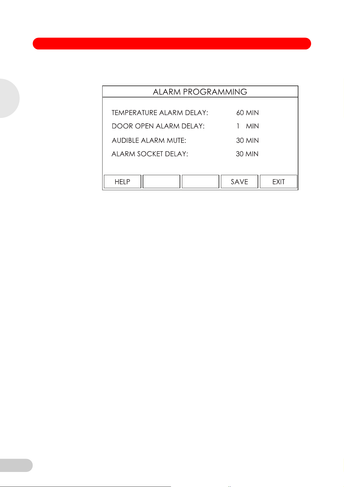
2. Press the ALARMS menu key.
The alarm programming screen will be displayed.
Abb. 6: Alarm programming screen
Fig. 6: Alarm programming screen
3. Using the º and » directional keys, select the alarm function to modify.
4. Use the ¶ and · directional keys to select among the preset options for each alarm feature.
5. Press the SAVE menu key to save your changes.
6.3.2 Temperature alarm delay
When the cabinet temperature is disturbed by opening the door, the temperature fluctuation can
inadvertently trigger a high temperature alarm. The TEMPERATURE ALARM DELAY,
programmable from 5 to 180 minutes, helps prevent false high temperature alarms by delaying
the high temperature alarm for a set period of time after the outer door is opened. If the freezer
temperature recovers to within the high and low temperature alarm settings during the set delay
period, no alarm will be triggered. If the freezer has not recovered within the set delay period, an
alarm will be triggered. The subsequent alarm can be muted (see Alarm mute and
acknowledgement on p. 23).
This programmable feature does not affect low temperature alarms, nor will it prevent an alarm in
the advent of a temperature fluctuation that is not the result of a door opening (for example, a
power failure).
6.3.3 Door open alarm delay
The DOOR OPEN ALARM DELAY, programmable from 1 to 10 minutes, provides the user with
an audible warning that the outer door has not been closed properly, or that the door is being held
open for a prolonged period of time. When the outer door is opened, a timer counts down the
programmed period of delay, after which the alarm is triggered if the door is still open.
6.3.4 Audible alarm mute
The AUDIBLE ALARM MUTE, programmable from 5 to 60 minutes, provides the user with a
means to delay the audible alarm from re-activating after an audible alarm has been muted.
When an audible alarm is activated, the alarm can be muted by pressing any directional key
when the main screen is displayed. The audible alarm will then be muted for the programmed
delay period before reactivating.
If the alarm condition clears before the delay period is over, the audible alarm will not re-activate
and the delay countdown will be cancelled.
6.3.5 Alarm socket delay
22
The ALARM SOCKET DELAY, programmable from 5 to 180 minutes, allows you to delay the
activation of the alarm monitoring socket during a temperature alarm.
Page 23

Innova® U360 -86 °C Freezers — Operating manual
When a temperature alarm is activated, alarm socket activation will be delayed for the
programmed period. If the alarm condition is still active after the delay period, the alarm socket
will activate.
In the case of a power failure or any non-temperature-based alarm (e.g., a sensor failure), the
alarm socket will activate immediately, and the delay period will be ignored.
6.3.6 Alarm mute and acknowledgement
When an alarm occurs, the audible alarm can be muted when the main screen is displayed by
pressing any directional key. The alarm log will record the time and date when the alarm was
muted, and the alarm will be muted for the selected delay period. The mute function will silence
all alarms active at the moment the mute button is pressed.
As an added level of security, alarm acknowledgment can be required. When alarm
acknowledgment function is turned on, a USER ID will be required to silence the alarm. When an
alarm is triggered, any attempt to mute an alarm will cause a USER ID selection screen to open.
The user will need to enter a USER ID, which will automatically be logged in the ALARM LOG to
identify the person who acknowledged or muted the alarm.
The alarm acknowledgement feature requires at least one USER ID to exist in the system. To
enter a USER ID:
1. Press the USER menu key.
2. Use the directional keys to select USER ID & PASSWORD from the list and press SELECT.
3. To enter a USER ID, use the directional arrow keys to select a USER ID position on the
screen to store the ID (any open position can be used), then press SELECT.
4. A menu-based alphanumeric selection window will appear. Use the directional arrow keys to
select each character and use the SELECT key to store each character. Use the menu key
to delete an entered character or DELETE to erase the entire ID.
5. When finished, press SAVE to store the new USER ID, then press EXIT to return to the
previous screen. If you press EXIT before you press SAVE, your changes will be discarded.
6. Once entered, the USER ID is functional and the ALARM ACKNOWLEDGMENT feature is
automatically activated.
7. If desired, ALARM ACKNOWLEDGMENT can be set to INACTIVE in the USER menu using
the directional keys without deleting any USER ID.
8. A USER ID can be deleted by opening the USER ID alphanumeric selection screen and
pressing the DELETE key, then the SAVE key.
6
Operation
6.3.7 Setpoint and security control
The freezer is delivered with all settings accessible to general users. Changes to the freezer
settings can, however, be protected from inadvertent or unauthorized changes. Up to eight user
names and passwords can be entered into the syst
passwords may make changes to the freezer settings.
1. To activate setpoint and ID security, press the USER menu key.
2. Use the directional keys to select USER ID & PASSWORD from the list and press SELECT.
3. If you wish to enter a USER ID, follow the instructions in (see Alarm mute and
acknowledgement on p. 23), Steps 3 - 5.
4. To require a PASSWORD when making any changes to the system settings, scroll the cursor
to the password position corresponding to the USER ID that requires the password and press
SELECT.
When you press SELECT, a menu-based alphanumeric selection window will appear. Use
the directional arrow keys to select each character and use the SELECT key (not the SAVE
key) to store each character. Use the menu key to delete an entered character or DELETE
to erase the entire password. All the characters you choose will appear as ***.
5. When finished, press SAVE to store the new PASSWORD , then press EXIT to return to the
previous screen. If you press EXIT before you press SAVE, your changes will be discarded.
6. Once saved, the password position next to the USER ID will be marked as ACTIVE. The only
way to deactivate a password is to delete it.
em so that only the specified users with
23
Page 24

6
Operation
Innova® U360 -86 °C Freezers — Operating manual
7. A PASSWOR D can be deleted by opening the password alphanumeric selection screen and
pressing the DELETE key, then the SAVE key.
If a USER ID is entered, ALARM ACKNOWLEDGEMENT is automatically activated. If alarm
acknowledgment is not required with the use of a password, this feature may be deactivated in
the USER menu system without affecting password control. Adding or adjusting a PAS SWO R D
only will not automatically turn on ALARM ACKNOWLEDGEMENT.
Once activated, a single password will lock the entire system and prevent any subsequent
changes to system settings, IDs or passwords without the use of a specific password matched to
a specific USER ID. Each combination of USER ID and PAS SWO RD is unique (one USER ID
cannot use the PASSWOR D of another USER ID to make system changes).
The USER IDs can be viewed at any time. Once a password is set, the USER SCREEN is not
generally accessible, and can only be accessed by a user who has a valid password. Passwords
are never visible to general users. Passwording does not prevent general users from viewing
data on the system at any time, including the alarm log.
Take care to note your password somewhere. If a password is forgotten, you must contact a
Hint!
6.3.8 Setting the temperature offset
customer service representative to recover or delete the forgotten password.
The calibration of the control system is carried out via the ENGINEERING (ENG) screen on the
display. To access the ENG screen, you will be required to enter the engineers’ code (*******).
1. Press the DIAG button, then press the ENG button.
2. Enter ENG code when prompted.
3. Press the left or right buttons on the directional keypad to set the desired temperature offset
values within the range of -10 to +10 °C.
4. Press EXIT to save and return to the main screen.
6.4 Audible alarm battery backup
The alarm system is protected by a battery backup system in the case of power and/or system
failure. The battery is designed to operate the audible alarm and data recording system for up to
24 hours. When a power failure occurs, with the battery switched on, the mains/power failure
audible alarm sounds immediately and the main display shuts off to conserve power.
You can activate the LCD screen by pressing any directional key. When you do, the internal
temperature will be displayed on the screen, which will remain on briefly, then shut down again to
conserve power. Be sure to take note of the following cautions:
Risk of material damage
Frequent operation of the display during a mains/power failure will substantially reduce the life
NOTICE!
of the alarm battery.
Opening the freezer door during a mains/power failure will increase the cabinet temperature.
Failure to turn on the alarm battery switch will disable the audible alarm system and data
recording during a mains/power failure.
The alarm battery backup system does not affect the external alarm monitoring socket. The alarm
socket is designed to operate regardless of the condition or state of the freezer or alarm battery.
The audible alarm should be checked periodically to verify its function:
1. Press the DIAG menu key to enter the diagnostics system.
2. Press and hold the TEST menu key for at least 5 seconds.
3. The audible alarm should sound repeatedly.
4. Press the EXIT menu key to return to the main screen.
24
Page 25

Innova® U360 -86 °C Freezers — Operating manual
1
2
3
6.5 Alarm monitoring socket
The freezers are provided with an alarm monitoring socket at the rear of the freezer and a
matching plug for external monitoring. This plug can be connected either to a central monitoring
system such as a building management system, or to a remote alarm.
Abb. 7: Alarm monitoring socket
Fig. 7: Alarm monitoring socket
1 RS-485 connector (optional) 2 Alarm monitoring socket
3 Mains/power socket
6
Operation
NOTICE!
The configuration of the socket is shown in (Fig. 8 on p. 25), as viewed from the rear of the
freezer. Within the freezer, the socket is connected to voltage-free contacts rated at 24 volts, 1
amp. In normal operation, with the mains/power on, pin 1 is connected to pin 2, and in the alarm
condition, with mains/power off, pin 1 is connected to pin 3.
The alarm socket should be checked periodically to verify its function.
1. Press the DIAG menu key to enter the diagnostics system.
2. Press and hold the TEST menu key for at least 5 seconds.
3. The alarm socket will switch to its alarm mode.
4. This can be verified by connecting an appropriately rated continuity testing device across the
contacts as described in the alarm socket diagram (Fig. 8 on p. 25).
5. Press the EXIT menu key to return the main screen.
Risk of material damage
Hazardous voltages must not be connected to the remote alarm socket. Max Rating 24 V 1 A.
Abb. 8: Remote alarm socket - upright f reezer
Fig. 8: Remote alarm socket - upright freezer
25
Page 26

6
Operation
Innova® U360 -86 °C Freezers — Operating manual
6.6 Data storage and viewing
The freezer is equipped with multiple sensors that help to maintain its operation and to warn of
conditions that can affect performance. Among the sensors are:
• A cabinet temperature probe
• An air-cooled condenser probe
• A cascade condenser probe
• An ambient temperature probe
• A door position sensor
The information from each sensor is recorded by the system processor, and updated to the
display screen and memory log. The system stores data from each of the sensors every 60
seconds.
Up to 30 days worth of stored data can be viewed anytime by pressing the DATA menu key and
selecting one of the DATA LOG choices.
• ALARM LOG
• CABINET & AMBIENT TEMPERATURE GRAPH
• 1ST STAGE CYCLING & CONDENSER TEMPERATURE GRAPH
• 2ND STAGE CYCLING & CONDENSER TEMPERATURE GRAPH
6.6.1 Alarm log
The alarm log records all alarms activated on the system in sequential order based upon their
time/date stamp. The most recent alarm appears at the bottom of the screen (see Fig. 9 on
p. 26). This log also records any alarm mute activity and alarm acknowledgements, including the
USER ID and time and date of acknowledgment.
Use the º and » directional keys to review any historical log data that is not visible on the screen.
The entire log can be cleared at any time by pressing the CLEAR menu button. To leave this
screen, press the EXIT menu key.
Abb. 9: Alarm log screen
Fig. 9: Alarm log screen
6.6.2 Cabinet and ambient temperature graph
Information about the internal cabinet temperature and ambient room temperature is viewable
through the CABINET & AMBIENT TEMPERATURE GRAPH. This graph provides a running
display of cabinet and ambient temperatures; it also identifies the time and duration of outer door
openings (see Fig. 10 on p. 27).
To allow for more detailed viewing, both the time and temperature scales may be expanded or
contracted by pressing the ZOOM X button to scale the X or time axis, and the ZOOM Y button to
scale the Y or temperature axis. The entire temperature log may be deleted by pressing the
DELETE key (see Fig. 10 on p. 27).
26
Page 27

Innova® U360 -86 °C Freezers — Operating manual
Historical data may be viewed by pressing the ¶ and · directional keys. The graph data may also
be adjusted up and down on the temperature scale using the º and » directional keys to realign
the graph for better viewing.
Abb. 10: Chamber & ambient temperature graph screen
1
6
Operation
2
35 4
Fig. 10: Chamber & ambient temperature graph screen
1 Cabinet temperature 2 Mains/power failure marking
3 Door opened 4 Door closed
5 Ambient temperature
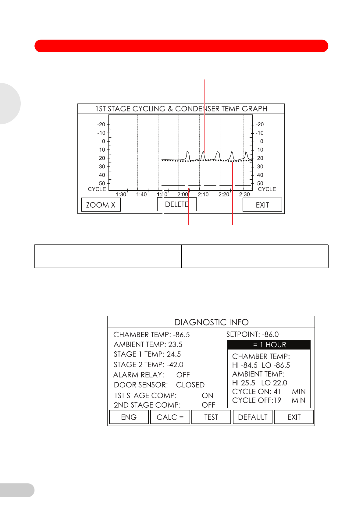
6.6.3 1st and 2nd stage cycling and condenser temperature graph
For diagnostic purposes, the system records and displays system temperatures relating to the
first and second stage refrigeration system. These graphs provide immediate access to vital
information regarding compressor operation and critical refrigeration temperatures. This
information is highly useful for evaluating or troubleshooting any performance issues. You can
move around in these graphs as in the CHAMBER & AMBIENT TEMPERATURE GRAPH
above. Each graph also displays the ambient temperature for reference.
27
Page 28
1
2
34
6
Operation
Innova® U360 -86 °C Freezers — Operating manual
Abb. 11: Chamber & ambient temperature graph screen
Fig. 11: Chamber & ambient temperature graph screen
1 Condenser temperature 2 Ambient temperature
3 Compressor off 4 Compressor on
6.7 Diagnostics
In order to quickly provide critical information for troubleshooting and monitoring performance
issues, the DIAG menu button opens the DIAGNOSTIC INFORMATION screen (see Fig. 12 on
p. 28), which provides an immediate overview of all critical parameters and also allows the user
to test critical functions.
Abb. 12: Diagnostic information screen
28
Fig. 12: Diagnostic information screen
See (Tab. on p. 29) for a description of each menu button function.
Page 29

Innova® U360 -86 °C Freezers — Operating manual
DIAG Screen
Button
ENG This button is ONLY for use by qualified service personnel. It requires a
CALC = Pressing this button allows the user to quickly view historical minimum and
TEST Pressing this button allows the user to verify the function of the audible alarm
DEFAULT Pressing this button quickly reverts all adjustable setpoints to the factory
EXIT Pressing this button returns you to the DATA LOG screen.
6.8 PS2 service data ports
The freezer is equipped with two PS2 data ports. They provide the ability for service personnel to
record information from the operating system and to upload revisions to the system’s firmware.
6.9 Voltage stabilizer
The U360 freezer (model 120 V, 60 Hz) has the option of an internal voltage stabilizer.
The optional internal voltage stabilizer automatically compensates for variations in the supply
voltage (in case of over-voltage, brown-outs, dips, sags and surges). The output is only switched
if the power disturbance is sustained for at least two seconds. (see Installing the voltage stabilizer
on p. 14).
The voltage stabilizer unit indication is displayed on the lower left front panel of the U360 freezer.
(see Fig. 1 on p. 10).
When you switch the freezer on, if the input voltage is within the specified range, the green LED
NORMAL will illuminate. If the voltage stays within the specified range, the green LED will remain
illuminated.
Sustained variations in the input power will be automatically compensated for by the stabilizer
circuit and indicated by a red LED for HIGH voltage or an amber LED for LOW voltage.
Description
factory-set password.
6
maximum (HI and LO) temperatures and to view compressor cycle run times
over a period of 1, 2, 3 or 6 hours, by sequentially pressing the button.
Operation
and the alarm socket relay.
setpoints. This action does NOT delete USER ID or PASSWORD information,
graph data or alarm log data.
29
Page 30

6
Operation
Innova® U360 -86 °C Freezers — Operating manual
Tab. 1: Voltage stabilizer specifications (120 V, 60 Hz model only)
120 V
Rated at 20 Amps
Line Voltage:
• Normal Freezer Operating Voltage 120 V ± 10 %
• Normal Voltage Stabilizer Operating Range (LED Green) 106 - 123 V
± 2.5 V
• Low (Boost) Voltage Limit (LED Amber) < 106 V
• High (Buck) Voltage Limit (LED Red) > 123 V
30
Page 31

Innova® U360 -86 °C Freezers — Operating manual
7 Maintenance
7 Maintenance
7.1 Cleaning
Risk of material damage
Maintenance, adjustment and repair work should be carried out only by QUALIFIED,
NOTICE!
7.1.1 Painted surfaces
7.1.2 Panels and shelves
7.1.3 Air intake grille and filter
EXPERIENCED personnel who have been AUTHORIZED to undertake such work by New
Brunswick Scientific or its authorized agents.
Failure to use authorized service agents will invalidate the warranty.
All exterior paint work and inner doors should be cleaned using a solution of mild detergent in
water. Do not use abrasive cleaners or solvents.
The interior panels and shelves are made of stainless steel. They may be cleaned and sterilized.
7
Maintenance
NOTICE!
7.1.4 Heated vent port
Hint!
Risk of material damage
Serious damage to the freezer may result if the air intake is blocked. Check that there is no
obstruction of the airflow to the freezer. The air intake filter must also be cleaned regularly.
Remove the filter from behind the grille by turning the thumbscrews ¼ turn and opening grille
downward. The filter should be washed in warm soapy water and left to air dry before
replacing.
The air intake grille must be cleaned regularly to keep it free from dust and debris. Under normal
conditions, clean the grille once every three months. If the area around the freezer is very dusty
or dirty, clean the grille more often.
Brush the grille with a soft brush and, if a vacuum cleaner is available, vacuum the dust from
the grille.
There is an electrically-heated vent port in the freezer which must not be allowed to become
blocked or sealed off.
Over a period of a few weeks, depending on how often the freezer is being used, a small
mushroom of ice will form around the end of the vent port. If the vent port is allowed to become
blocked, a vacuum will be created when the door is closed. It will not be possible to open the door
or lift the lid until the vacuum has leaked away through the seal, which can take up to two hours
due to the high quality of the seals.
The vent port is located on the left-hand side of the freezers.
If the door cannot be opened, clear the vent port by pressing the manual plunger on the
outside of the air vent.
31
Page 32

7
7.1.5 Door or lid seal
Maintenance
Innova® U360 -86 °C Freezers — Operating manual
123
1Plunger 2Cover
3 Freezer outer wall
Be sure to treat the door or lid seal with care. Avoid damaging this seal in any way. The freezer
cannot operate properly with a defective seal.
It is advisable to wipe both the seal and the surface against which it seals with a soft dry cloth
once a month.
7.2 Routine maintenance
7.2.1 Lubrication
Every 12 months the outer door hinges and the handle mechanism should be lightly lubricated
using general-purpose oil or spray grease.
7.2.2 Defrosting
After an extended period of operation, defrosting may become necessary:
Risk of material damage
Do not attempt to chip or scrape the ice with a sharp instrument. Allow the ice to melt
NOTICE!
naturally.
1. De-activate the alarm by switching the battery (alarm) switch (located behind the lockable
panel on the front of the freezer) to (O).
2. Unplug the freezer from the mains/electrical supply.
3. Leave the inner and outer doors or lids open.
4. Allow the accumulated ice to melt.
5. Mop up the resulting water.
6. Dry and decontaminate the interior of the freezer.
7. When defrosting is complete, reconnect the freezer to the mains/electrical supply.
8. Turn the mains/power switch on (I) and re-activate the battery (alarm) switch.
7.2.3 Removing the inner doors
32
The inner doors of the freezer can be removed for defrosting and cleaning.
1. Fully open the outer door of the freezer.
2. Fully open the inner door.
Page 33

Innova® U360 -86 °C Freezers — Operating manual
1
2
3. Lift off inner door from hinges and set aside.
Abb. 13: Lift-off inner door
Fig. 13: Lift-off inner door
1 Inner door 2 Lift-off hinge
7
Maintenance
7.2.4 Replacing the inner door
7.2.5 Electrical components
WARNING!
Repeat procedure for each door.
1. Fully open the outer door of the freezer.
2. Fit door to hinge pins and close.
3. Check to ensure that inner door gasket is sealing against the freezer trim.
4. If required, adjust the latch retainer by loosening the screws and moving forward or
backwards.
5. Close outer door.
Risk of personal injury
All electrical components that could cause possible ignition of refrigerant vapor during normal
operation have been enclosed in an IP65 enclosure.
During routine maintenance, care must be taken to avoid any damage to the gaskets and
sealing grommets of these enclosures; also check the gaskets and sealing grommets
routinely to ensure their integrity. Should any damage or deformity be detected, the gasket
and/or sealing grommet must be replaced immediately.
Failure to observe this safety warning will invalidate the warranty and could result in a
dangerous situation.
Audible alarms
Regularly check the audible alarm:
Press and hold the TEST key in the DIAGNOSTIC INFORMATION screen.
33
Page 34

7
Innova® U360 -86 °C Freezers — Operating manual
Battery replacement
The 6.0 V Cyclon battery is mounted within the compressor housing, near the interface board,
located behind the left-hand base cover on the freezers.
Risk of material damage
Use only a replacement battery of the correct type and part number.
NOTICE!
Hint!
The battery must be fitted so the terminals correspond to the polarity labels on the electrical
panel.
To replace the battery:
1. Switch off the mains/power switch and disconnect the mains/power supply.
2. Remove the side cover and the screws that secure the battery to the housing panel.
3. Disconnect the battery terminals.
4. Install the new battery, fixing screws, and the side cover.
Be certain, when reconnecting the battery, to respect the correct polarity (red is + positive and
black is – negative).
Maintenance
5. Reconnect the freezer to the mains/power supply and turn the mains/power switch on (I).
Fuses
Fuses must be replaced by a New Brunswick Scientific approved service engineer. Contact New
Brunswick Service.
34
Page 35

Innova® U360 -86 °C Freezers — Operating manual
8 Troubleshooting
8 Troubleshooting
8.1 General errors
If you are experiencing a problem with your freezer, check the following troubleshooting guides
before contacting your New Brunswick authorized Service technician.
8.1.1 Safety alarms
Symptom/
message
Door will not
open
Cause Remedy
• The door handle is locked.
• The heated vent port is
blocked.
Unlock the door handle.
Break up the ice in the vent port using the
hand bolt (see Heated vent port on p. 31).
If the door will not open:
Call New Brunswick Service.
More than
one voltage
stabilizer
LED lights
up
No voltage
stabilizer
LED lights
up
The system is designed to prevent the user from accidentally turning the alarm system off. The
system will trigger the temperature alarms if the freezer temperature is outside the alarm
temperature setpoints when any of the following occurs:
• Voltage stabilizer may have
failed.
• Voltage stabilizer may have
failed.
Call New Brunswick Service.
Call New Brunswick Service.
• Initial System Start-up
• Mains/Power Failure (then return to operation)
• Temperature Setpoint Change
The alarm can be muted until the freezer returns to within the alarm setpoints.
8
Troubleshooting
8.1.2 Mains/power failure
If mains/power cannot be restored in a timely fashion, the audible alarm and controller/display
power can be permanently disabled by opening the lockable mains/power switch cover plate and
physically placing the battery alarm switch in its off position. This will also shut down all data
recording.
8.1.3 Inner doors
The upright freezers are fitted with internal doors which latch shut, minimizing temperature rise
when the outer door is opened. Inner door gaskets require the door to be latched at all times
when the freezer is running in order to be effective. Failure to latch the inner doors properly will
lead to ice buildup between the outer and inner doors, and under the inner door seals. The inner
doors can easily be removed and de-iced via their lift-off hinges. Make sure they are thoroughly
dry before returning them to service.
8.2 Error messages
Your electronically-controlled New Brunswick freezer incorporates a microprocessor-controlled
system to troubleshoot, diagnose and report faults and problems in its electronic and refrigeration
systems. The system uses plain language where appropriate to describe the problem and
suggest corrective actions.
This table interprets error codes that may appear in the control panel display:
35
Page 36

Innova® U360 -86 °C Freezers — Operating manual
8
Troubleshooting
Symptom/message Cause Remedy
HIGH CONDENSER
TEMP CHECK AIR
FILTER
HIGH CONDENSER
TEMP CHECK ROOM
TEMP
EXCESSIVE
CONDENSER TEMP
THERMAL OVERLOAD
FREEZER WILL
REMAIN OFF UNTIL
SYSTEM COOLS
HIGH CASCADE
TEMPERATURE
HIGH AMBIENT
TEMPERATURE
LOW AMBIENT
TEMPERATURE
Air-cooled condenser
temperature too high:
1. Filter may be blocked.
2. Ambient temperature may be
too high.
If alarm continues to sound:
• Fan may have failed.
Air-cooled condenser
temperature too high:
1. Ambient temperature may be
too high.
2. Freezer airflow may be
blocked or heated air from
other equipment is being
drawn into the freezer’s air
intake.
If alarm continues to sound:
• Fan may have failed.
Freezer will automatically shut
down if critical condenser
temperature is reached to avoid
system damage.
A high cascade condenser
temperature may indicate a
refrigeration problem.
Room temperature has
exceeded 34 °C. If room
temperature is not reduced, it
may affect freezer performance.
Room temperature has dropped
below 10 °C. If room
temperature is not increased,
low ambient temperature may
affect performance.
1. Clean filter according to the
instructions (see Air intake
grille and filter on p. 31).
2. Cool the room.
Call New Brunswick Service
department.
1. Reduce the room
temperature.
2. Remove restrictions to air flow
and make sure no other
equipment is forcing hot air
into the freezer intake.
Call New Brunswick Service
department.
Thermal fuse will automatically
reset after system cools.
Call New Brunswick Service
department.
Reduce room temperature
Increase room temperature
36
Page 37

Innova® U360 -86 °C Freezers — Operating manual
Symptom/message Cause Remedy
DOOR OPEN ALARM
DOOR OPEN: X SEC
(MIN)
LOW BATTERY ALARM
BATTERY CHARGE IS
LOW
CHAMBER SENSOR
FAILURE
CASCADE SENSOR
FAILURE
CONDENSER SENSOR
FAILURE
AMBIENT SENSOR
FAILURE
ELECTRICAL FAULT General message for electrical
POWER FAILURE
POWER OFF: X SEC
(MIN, HRS)
ALARM MUTED X SEC
(MIN)
SYSTEM WILL RE-LOCK
AFTER X SEC
System records & displays time
during which outer door is held
open.
Message is displayed when the
alarm battery charge is low.
Chronic low battery charge is
indicative of a defective or worn
battery.
PT100 Probe 1 failure. This
probe, located inside the freezer
cabinet, indicates cabinet
temperature.
This probe monitors the cascade
condenser.
This probe monitors the
air-cooled condenser
temperature.
This probe monitors the ambient
air temperature.
faults not including those listed
above.
System records & displays
accumulated time since a power
failure occurred.
Whenever an alarm is muted, the
alarm delay countdown is
displayed to advise when the
audible alarm will reactivate.
Whenever a password is used to
unlock the system, the system
will automatically relock to
prevent further changes after the
system returns to the main
screen.
Close freezer outer door.
Replace battery, (see Battery
replacement on p. 34).
Call New Brunswick Service
department.
Call New Brunswick Service
department.
Call New Brunswick Service
department.
Call New Brunswick Service
department.
Call New Brunswick Service
department.
N/A
N/A
N/A
8
Troubleshooting
37
Page 38

9 Technical data
9 Technical data
9.1 Specifications
Part No. U9425-000X*
Internal Dimensions:
Height x Width x Depth
External Dimensions:
Height x Width x Depth
Capacity 360 Liters
Net Weight 230 kg
9
Lock Standard
No. Compartments 3
Interior Stainless steel grade 304L
Alarms High/Low temperature, power fail, battery low, filter clean, door open, electrical fault
Insulation Material Vacuum insulation panels and urethane foam
Remote alarm port Standard
PS2 Ports (2) Standard
Technical data
RS-485 interface Optional
Refrigerants: High Stage Refrigerant: R404A / Low Stage Refrigerant: R508B
‡Power Consumption:
• 120 V electrical supply 487 Watts
• 230 V electrical supply 492 Watts
Mains/Power Source and Current Rating:
120 V, 60 Hz 16.5 A
230 V, 50 Hz 6.5 A
Pull Down Time: From +25 °C to -85 °C (freezer empty; 230 V, 50 Hz electrical supply)
Innova® U360 -86 °C Freezers — Operating manual
Model No. U360
1365 x 440 x 615 mm
53.7 x 17.3 x 24.2 in
1950 x 600 x 867 mm
76.8 x 23.6 x 34.1 in
12.7 cubic feet
506 lb
~5.7 hours
Performance -50 °C to -86 °C at 32 °C maximum ambient operating temperature
Environmental Conditions All freezers use components tested to CE/UL specifications listed below:
• Indoor use
• Altitude up to 2000 m
• Ambient temperature range 10 °C to 32 °C
• Maximum relative humidity 80 % for temperatures up to 31 °C, decreasing linearly to
50 % relative humidity at 40 °C
• Mains/power supply voltage fluctuations not to exceed ± 10 % of the nominal voltage
• Installation category II
• Pollution degree 2
* X = 0 for 120 V, or 1 for 230 V
‡ Freezer set to -80 °C, ambient 20 - 25 °C at rated mains/electrical supply
38
Page 39

Innova® U360 -86 °C Freezers — Operating manual
10 Ordering Information
10 Ordering In formation
10.1 Accessories
A number of accessories are available for New Brunswick's range of ultra-low temperature
freezers. Contact your local New Brunswick representative or distributor for details.
10.1.1 A2 independent temperature monitor
The A2 system is an independent temperature monitor with alarm, electronic chart recorder, and
auto-dialer that communicates via the internet for remote monitoring from anywhere in the world.
Ask your New Brunswick sales representative for availability.
10.1.2 Auto-dialers
Auto-dialers can call a set of preprogrammed telephone numbers in the event of an alarm
condition and connect right into the freezer's remote alarm port.
10.1.3 Temperature probes
Additional Temperature Probes (such as the New Brunswick A2 monitoring system) can be
installed upon request for an external alarm system or for validation.
10.1.4 Validation packages
Installation and operational qualifications are available.
10.1.5 Padlock adapter kits
Padlock adapter kits allow up to two user-supplied padlocks to be secured to outer door handle
for extra security.
10.1.6 CO
and LN2 back-up systems
2
These systems are available to temporarily protect the contents of the freezer against the
consequences of freezer failure or power failure. In an emergency, the system can inject either
liquid carbon dioxide or liquid nitrogen from a storage bottle. Carbon dioxide back-up systems will
maintain temperatures between -40 °C and -70 °C (subject to environmental conditions) for a
period of up to 48 hours, during which time the freezer can be repaired. Liquid nitrogen back-up
systems will maintain the freezer temperature at -86 °C.
CO
2
distributor for options available. Instructions are included in the kit.
Order No.
(International)
U9043-0002 CO
U9043-0004 CO
U9044-0002 LN
U9044-0004 LN
and LN2 back up systems can be retrofitted by the user. Contact your local New Brunswick
Description Quantity
Back-up System, 120 V, 60 Hz 1
2
Back-up System, 230 V, 50 Hz 1
2
Back-up System, 120 V, 60 Hz 1
2
Back-up System, 230 V, 50 Hz 1
2
10
Ordering Information
10.1.7 Inventory racking systems
A very comprehensive set of anodized aluminium racks is available. These are designed to
accommodate various sizes of boxes neatly, while giving maximum packing density in the
freezer. Stainless-steel shelves and water proof boxes as well as custom racking are also
available.
39
Page 40

Innova® U360 -86 °C Freezers — Operating manual
10
Order No.
(International)
K0641-3000 2” Aluminum Box Rack 1
K0641-3001 3” Aluminum Box Rack 1
K0641-3002 4” Aluminum Box Rack 1
10.1.8 Chart recorder
A chart recorder is available to provide a continuous record of the temperature inside the freezer
over a period of seven days. The record is presented on a circular chart.
The following items are available for all freezer models:
Order No.
(International)
K0440-0355 Chart Recorder Kit 1
K0540-0025 Chart Recorder Paper 100
K0660-0051 Chart Recorder Pens 3
10.1.9 New Brunswick BioCommand SFI datalogging software (RS-485 interface)
New Brunswick Scientific's BioCommand
archive data from as many as 32 shakers, CO2 incubators, and/or freezers, simultaneously. This
PC-based software works with any OPC-compliant equipment with an RS-232 or RS-485 port.
Description Quantity
Description Quantity
®
SFI Track and Trend software is available to trend and
Ordering Information
40
Page 41

Innova® U360 -86 °C Freezers — Operating manual
11 Transport, storage and disposal
11 Transport, storage and disposal
11
11.1 Shut down
11.2 Transport
WARNING!
CAUTION!
11.3 Disposal
Switch the battery switch off before transporting or storing the equipment.
Risk of personal injury
Lifting and transporting the freezer without suitable equipments can result in crushing and other
injuries.
Use a mechanical lifting equipment to load and unload the freezer.
Risk of material damage
Vibrations and impacts can cause the hermetically sealed compressors to slip out of their
suspension system.
Do not tilt the equipment.
Avoid vibrations and impacts.
Perform the following steps if relocation is necessary:
1. Remove all shelves, racks, and boxes.
2. Carefully move the freezer.
In case the product is to be disposed of, the relevant legal regulations are to be observed.
Information on the disposal of electrical and electronic devices in the European
Community:
Within the European Community, the disposal of electrical devices is regulated by national
regulations based on EU Directive 2002/96/EC pertaining to waste electrical and electronic
equipment (WEEE).
According to these regulations, any devices supplied after August 13, 2005, in the
business-to-business sphere, to which this product is assigned, may no longer be disposed of in
municipal or domestic waste. To document this, they have been marked with the following
identification:
Transport, storage and disposal
Because disposal regulations may differ from one country to another within the EU, please
contact your supplier if necessary.
In Germany, this is mandatory from March 23, 2006. From this date, the manufacturer has to offer
a suitable method of return for all devices supplied after August 13, 2005. For all devices supplied
before August 13, 2005, the last user is responsible for the correct disposal.
41
Page 42

DECLARATION OF CONFORMITY
New Brunswick Scientific declares that the Ultra Low Temperature Freezers products listed
conform to the European Union Directives and Standards identified in the declaration.
Innova U101
Innova U360*
Innova U535 Premium U410
Innova U725 Premium U570
Innova C585 Premium C340
Innova C760 Premium C660
Marked Complies with EC directive 93/68/EEC
Electromagnetic Compatibility (EMC) 89/336/EEC & Amendment 92/31/EEC
Test Standard BS EN 55014-1 : 1997
Test Standard BS EN 55014-2 : 1997
Test Standard BS EN 61000-3-2 : 1995
Test Standard BS EN 61000-3-3 : 1995
*Test Standard EMC EN61326 : 1997 A1, A2 (U360 only)
Low Voltage Directive (LVD) 73/23/EEC
Test Standard EN 61010-1 : 1993 Amendment A2 : 1995
Test Standard ISO 5149 : 1993 (E)
UL 61010A-1 CSA C22.2 No. 1010.1 UL File E234047 (U.S. Voltage Models)
Conducted/Radiated Emissions FCC Part 15 Class B (U.S. Voltage Models)
Approved by _
_________ on this 26th day of August, 2011
M. King. Managing Director UK Operations
New Brunswick Scientific Co., Inc., 44 Talmadge Road, Edison, NJ 08818, USA
New Brunswick Scientific (UK) Ltd, 17 Alban Park, St. Albans, AL4 0JJ, UK
New Brunswick Scientific BV, Kerkenbos 1101, Nijmegen 6546 BC, NL
12
Innova® U360 -86 °C Freezers — Operating manual
12 Certificates
12 Certi ficates
Certificates
42
Page 43

Innova® U360 -86 °C Freezers — Operating manual
Index
Index
A
Accessories .....................................................................39
Air intake..........................................................................31
Alarm activation ...............................................................19
Alarm delay, door open ....................................................22
Alarm delay, temperture...................................................22
Alarm functions ................................................................21
Alarm mute and acknowledgement..................................23
Alarm socket delay...........................................................22
Audible alarm mute..........................................................22
Auto-dialers......................................................................39
Auto-reset ........................................................................12
Automatic reset................................................................12
B
Battery activation .............................................................19
Battery replacement.........................................................34
C
Caution, explanation of ......................................................7
CFC ...................................................................................8
Chart recorder..................................................................40
Cleaning.....................................................................31, 32
Clearance ........................................................................13
CO2 back-up system........................................................39
Control panel ...................................................................16
Copyright ...........................................................................2
Custom-made racks.........................................................39
D
Danger, explanation of .......................................................7
Defrosting ........................................................................32
Disposal ...........................................................................41
Door seal .........................................................................32
Door/lid stuck ...................................................................20
E
Electrical connection........................................................18
Electrical requirements ....................................................18
Error codes ......................................................................35
Extended warrenty option ................................................12
External monitoring..........................................................25
F
Fuses ...............................................................................34
H
Hazard symbols .................................................................7
HCFC.................................................................................8
HFC ...................................................................................8
High/low temperature alarm setpoints............................. 20
I
Ice in vent .................................................................. 20, 31
Inner door, installing ........................................................ 33
Inner door, removing........................................................ 32
Inspection of boxes.......................................................... 10
Installing inner door ......................................................... 33
Intended use...................................................................... 9
L
Lid/door stuck ..................................................................20
LN2 back-up system ........................................................39
Lockable panel ................................................................ 19
M
Mains/power cord ............................................................18
Mains/power supply......................................................... 18
Manual conventions........................................................... 7
min.....................................................................................8
Modifying alarm functions................................................ 21
Monitoring.................................................................. 25, 40
Moving freezer................................................................. 41
Muting alarm.................................................................... 22
N
Notice, explanation of ........................................................ 7
P
Packing list verification ....................................................11
Panel, removing............................................................... 18
Part numbers................................................................... 40
Plunger ......................................................................20, 31
Power fail ......................................................................... 19
Power supply/mains......................................................... 18
R
Racks............................................................................... 39
Recorder pens................................................................. 40
Recorder, chart ................................................................40
Registration, warranty...................................................... 12
Remote alarm.................................................................. 19
Remote monitoring ....................................................25, 40
Removing inner doors .....................................................32
Removing lockable panel ................................................18
Removing upright freezer lock barrel...............................14
rpm ....................................................................................8
RS-485 computer interface.............................................. 40
S
Safety ................................................................................9
Setpoint and security control ........................................... 23
Index
43
Page 44

Index
Innova® U360 -86 °C Freezers — Operating manual
Setting temperature alarm setpoints................................20
Setting the operating temperature ...................................20
Specifications, U360 ........................................................38
Specifications, voltage stabilizer......................................30
Symbols used ....................................................................7
System sensors ...............................................................21
T
Temperature offset, setting ..............................................24
Temperature probes.........................................................39
Testing alarm ...................................................................33
Trademarks........................................................................2
Troubleshooting ...............................................................35
Turning on the equipment ................................................18
U
U360 Specifications .........................................................38
U360 upright freezer, front view.......................................10
U360 upright freezer, side and front views ......................10
Unpacking boxes .............................................................11
Using this manual ..............................................................7
V
Vacuum effect ..................................................................20
Validation packages.........................................................39
Vent............................................................................20, 31
Voltage stabilizer........................................................29, 29
Voltage stabilizer operation..............................................29
Voltage stabilizer specifications .......................................30
Voltage stabilizer, description ..........................................29
W
Warning, explanation of .....................................................7
Warranty ..........................................................................12
Warranty, extended ..........................................................12
44
Page 45

Eppendorf offices
Page 46

New Brunswick Scientific • www.nbsc.com • bioinfo@nbsc.com • For your local sales office or distributor contact:
Eppendorf AG · 22331 Hamburg · Germany · Tel: +49 40 538 01-0 · Fax: +49 40 538 01-556 · E-mail: eppendorf@eppendorf.com
New Brunswick Scientific Europe B.V. · Nijmegen · The Netherlands · Tel: +31 (0) 24 3717 600 · Email: europe@nbsbv.nl
Eppendorf North America, Inc. · Hauppauge, N.Y. USA · Tel: +1 516 334 7500 · +1 800 645 3050 · E-mail: info@eppendorf.com
Application Support Europe, International: Tel: +49 1803 666 789 · E-mail: support@eppendorf.com
North America: Tel: +1 800 645 3050 menu option 2 · E-mail: techserv@eppendorf.com
Asia Pacific: Tel: +603 8023 6869 · E-mail: support_asiapacific@eppendorf.com
 Loading...