

Page 1

FemtoJet express
®
Bedienungsanleitung · Operating Manual
Page 2

Inhalt / Table of contents
Bedienungsanleitung. . . . . . . . . . . . . . . . . . . . . . . . . . . . . . . . . . . . . . . . . . . . . . . . . . . . . . . . . . 3
Operating Manual . . . . . . . . . . . . . . . . . . . . . . . . . . . . . . . . . . . . . . . . . . . . . . . . . . . . . . . . . . . 51
EG-Konformitätserklärung
EC Conformity Declaration . . . . . . . . . . . . . . . . . . . . . . . . . . . . . . . . . . . . . . . . . . . . . . . . . . . 101
Inhalt / Table of contents
Nachdruck und Vervielfältigung – auch auszugsweise – nur mit Genehmigung.
No part of this publication may be reproduced without the prior permission of the copyright owner.
©
Copyright
eppendorf is a registered trademark. Printed in Germany
2
2005 Eppendorf AG, Hamburg
Page 3

Table of contents
1 Safety precautions and application .......................................................................... 53
2 Device description ...................................................................................................... 55
2.1 Overview ....................................................................................................................... 56
2.2 Short description .......................................................................................................... 57
2.3 Startup .......................................................................................................................... 60
3 Mode of operation ...................................................................................................... 62
3.1 Display, variable regulators and keypad ....................................................................... 62
3.1.1 Setting the injection parameters ................................................................................... 62
3.1.2 Variable regulators ........................................................................................................ 63
3.1.3 Keypad .......................................................................................................................... 63
3.2 Hand control / foot control ........................................................................................... 66
3.3 Connecting the capillary holder .................................................................................... 67
3.4 Information on working practices ................................................................................. 68
3.4.1 Compensation pressure pc ........................................................................................... 70
3.4.2 Injection pressure pi ...................................................................................................... 70
3.4.3 Injection time ti .............................................................................................................. 70
3.4.4 Clean function ............................................................................................................... 71
3.4.5 Manual or automatic injection ...................................................................................... 71
3.4.6 Constant pressure / constant working pressure............................................................ 71
3.5 The first injection .......................................................................................................... 72
3.6 Connecting an Eppendorf Micromanipulator ............................................................... 73
3.7 Functions ...................................................................................................................... 75
3.7.1 Changing the capillaries ............................................................................................... 75
3.7.2 Setting the pressure unit ...............................................................................................75
3.7.3 Switching on/off the loudspeaker ................................................................................. 75
3.7.4 Switching on/off the background illumination of the display ........................................ 76
3.7.5 Constant pressure ........................................................................................................ 76
4 Cleaning and Service................................................................................................... 77
4.1 Cleaning ........................................................................................................................ 77
4.2 Disinfection ................................................................................................................... 77
4.3 Decontamination prior to shipping ............................................................................... 77
4.4 Service .......................................................................................................................... 77
5 Troubleshooting .......................................................................................................... 78
5.1 Potential errors ............................................................................................................. 78
5.1.1 Self-test ........................................................................................................................ 79
5.2 Warnings ....................................................................................................................... 80
5.3 Error messages .............................................................................................................82
Table of contents
6 Technical data ............................................................................................................. 88
7 Ordering information .................................................................................................. 89
7a Ordering information for North America ................................................................... 92
51
Page 4

Table of contents
8 Index ............................................................................................................................. 95
Appendix A
Operation via a computer ........................................................................................... 97
A.1 Description of interface ................................................................................................. 97
A.2 Commands and queries ............................................................................................... 97
Table of contents
52
Page 5

1 Safety precautions and application
•
Observe operating instructions!
•
The device is only designed for use in the research lab!
•
The FemtoJet express is a lab device. It may only be operated by appropriately qualified lab
personnel.
•
Only use the device for microinjection under observance of all relevant legal regulations!
•
Before plugging in the device, please compare your voltage requirements with the
specifications on the identification plate!
•
The unit may not be connected to a socket that is not grounded! Use the appropriate mains
cable.
•
Electrical connections may be effected only when the device is switched off!
•
The unit may be opened only by authorized service personnel!
Potentially lethal voltage inside the unit.
•
Do not use the unit if damaged. This applies in particular when the mains cable is damaged.
•
The connection of the pressure tube to the high-pressure flasks, compressors or building
pressure systems is not part of these operating instructions! The connection may only be
carried out by trained personnel or tradesmen, taking into account the local regulations.
•
The device may only be operated with dry, non-oiled, pressurized air or purified nitrogen
gas with 4000 hPa to a maximum of 8000 hPa (4 bar – 8 bar, 58 PSI – 116 PSI)!
Other gases are not permitted!
•
Loud hissing may occur when coupling or uncoupling the pressure tube! Don't be alarmed!
When coupling, hold the ears at an adequate distance from the coupling!
•
The pressure tube of the external pressure supply is not permanently UV light resistant.
When using, for example, under a sterile bench with UV sterilization, this should be taken
into account, and the pressure tube should, where necessary, be removed prior to UV
sterilization.
•
This pressure tube may not be bent. The smallest bending radius is 50 mm.
Hold the pressure tube tightly when uncoupling! The brief pressure surge when uncoupling
•
can cause the pressure tube to fly off! Following the uncoupling, the pressure tube remains
under pressure when the pressure is not released using the Standby function!
If the unit is not used in accordance with purpose for which it is intended, its protective
•
function may be impaired.
•
•
Caution!
Take care when mounting glass capillaries or tools!
Mounting must always take place without the use of pressure!
Capillaries which have been mounted incorrectly may break loose under pressure.
Never point mounted capillaries at persons.
Caution!
Take care when using glass capillaries! During mounting or when placed upon a
hard surface, the glass capillaries may break and glass splinters may cause injury.
It is therefore essential to wear eye protection!
1
Safety precautions and application
53
Page 6

1 Safety precautions and application
•
In the case of independently-manufactured capillaries, ensure that the outer diameter of the
capillary corresponds to the specifications of the capillary grip head.
•
Over longer idle periods the device should be separated from the pressurized air supply and
then depressurized using the key and stored switched off!
1
•
Use the unit only for the described purpose! The unit and in particular the high pressure of
the Clean function may not be used for purposes other than microinjection!
•
Transfer
If the device is passed on to someone else, please include the instruction manual.
•
Disposal
In case the product is to be disposed of, the relevant legal regulations are to be observed.
•
Information on the disposal of electrical and electronic devices in the European Community
The disposal of electrical devices is regulated within the European Community by national
regulations based on EU Directive 2002/96/EC on waste electrical and electronic equipment
(WEEE).
According to these regulations, any devices supplied after 13.08.05 in the business-tobusiness sphere, to which this product is assigned, may no longer be disposed of in
municipal or domestic waste. They are marked with the following symbol to indicate this.
•
Safety precautions and application
•
•
•
As disposal regulations within the EU may vary from country to country, please
contact your supplier if necessary.
Use only original Eppendorf accessories. Only original accessory parts may be used.
The only exceptions are auxiliary pieces of equipment recommended by the manufacturer.
Otherwise all claims under guarantee and liability become void immediately. Use other
accessories only if you have a certificate from Eppendorf AG confirming technical safety in
use.
The responsibility for the correct functioning of the device passes onto the owner or user if
the device is maintained or serviced improperly by persons not belonging to the service
team authorized by Eppendorf or if used for a purpose other than that intended. Guarantee
and conditions of liability of the terms of sale and delivery of Eppendorf AG are not
expanded by the above notes.
The Eppendorf AG reserves the right to make technical alterations to this device!
54
Page 7

2 Device description
The FemtoJet® express enables minute quantities of liquid to be injected into cells. The relevant
parameters (injection pressure pi and injection time ti) are set using the variable regulators.
The key or connected hand or foot control or the INJECT key of the connected
micromanipulator are used to trigger these two parameters. If no injections are being
performed, compensation pressure pc is applied permanently.
The connection of an external pressure supply enables faster injections, even with higher
pressure.
2
Device description
55
Page 8

2 Device description
2.1 Overview
2
Device description
1
2
3
4
1 Display
– Displays relevant parameters during injection or setting of parameters.
– Guides operator through functions.
2 Keypad
– To trigger actions.
– To call up the function menu.
– To switch to and from Standby mode.
3 Variable regulators
– To set parameters injection pressure p
– To select functions and parameters in Function mode.
4 Tube connection
– Connect the injection tube for the capillary holder to the device via the bayonet connection.
56
, injection time ti and compensation pressure pc.
i
Page 9

2 Device description
Standard accessories:
1 Pressure tube, 2,5 m, G 1/4-inch for external pressure supply incl. couplings
1 Injection tube, 2 m
1 Universal capillary holder with grip head 0 for capillary diameters
of 1.0 mm and adapter for Femtotips
1 Hand control for triggering injection and the Clean function
1 Femtotips®, Femtotips® II and Microloader
1 Mains cable
1 Operating manual
Optional accessories:
1 Foot control for triggering the Inject function
1 Connecting cable (Interface Cable 5171) to the Micromanipulator 5171 or InjectMan
®
2
Device description
®
57
Page 10

2 Device description
2.2 Short description
Display
Display of all relevant parameters and information.
2
Function keys
Device description
Clean
To apply the maximum pressure for cleaning the capillary to the tube outlet.
Auto / Manu
To switch between manual and automatic time-controlled injection.
Count
To reset to zero the counter for injections which have been actuated.
58
Inject
To execute automatic or manual injection.
Menu
To switch the device to menu control; selected functions may be executed.
Standby
When the key is pressed briefly:
To switch the device between operating mode and standby mode or vice
versa.
When the key is held down:
As above, but also deairs the valve system.
Page 11

2 Device description
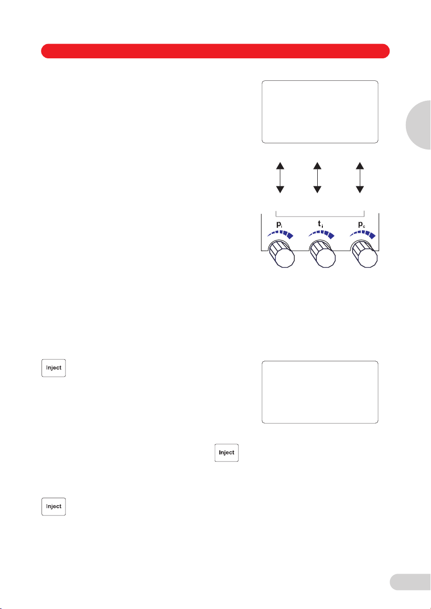
Variable regulator
In the normal operating mode, the parameters for injection are set by the three variable
regulators. The arrangement of the variable regulators corresponds to the arrangement of the
parameters in the two bottom lines of the display:
From left to right: injection pressure pi, injection time ti and compensation pressure pc.
In other operating modes, the variable regulators have either the significance indicated in the
display or no significance at all.
Tube connection
The injection tube for the capillary holder is connected to the device via the bayonet connection.
2
Device description
59
Page 12

2 Device description
2.3 Startup
2
Device description
Fig. 2: Diagram of rear of device
– Electrical connection is effected via the mains socket with integrated mains switch (1).
– The connection to the external pressure supply (2) takes place via the delivered pressure
tube, 2.5 m.
– Connection to an Eppendorf manipulator designed for injection is effected via the 15-pin
interface (3).
– Optional switches (e.g. foot control, hand control) or a computer can be connected to the
9-pin interfaces (4).
4
4
3
2
1
60
Page 13
2 Device description
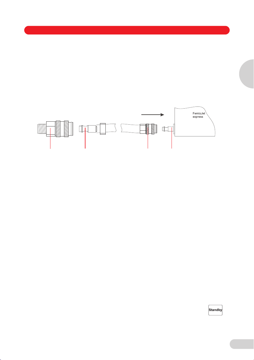
Connection of the external pressure supply
Dry, non-oiled, compressed air or purified nitrogen gas is to be used!
Pressure range from 4000 hPa to a maximum of 8000 hPa (4 bar – 8 bar, 58 PSI – 116 PSI),
constant pressure.
The connection for the external pressure supply is found on the rear side of the device.
Remove the black plastic cap.
The delivered pressure tube can be connected directly to the device.
2
Device description
1
Fig. 3: pressure tube, 2.5 m
1 Quick-lock coupling for mounting on the compressor, building pressure system
(e.g. when no connection system is available in the lab)
2 Plug sleeve, for coupling 1
3 Quick-lock coupling for connection to the FemtoJet
4 Plug sleeve to the FemtoJet® express, for coupling 3
The connection to the compressor, compressed air flask or building system can take place with
the supplied lock coupling (G1/4-inch threaded) or must be adapted by building services to the
existing connections.
The connection of the pressure tube to the high-pressure flasks, compressors or building
pressure systems is not part of these operating instructions!
Switching on the device
Connect the device to the external pressure supply. The injection tube may not be connected
when switching on and during the initialization phase.
Set the mains switch on the rear of the device to "I".
After being switched on, the unit runs through an initialization phase with self-test and valve
adjustment. Duration of approx. 1 minute.
Switching off the device
If it is not going to be used for an extended period, the device is to be separated from the
external pressure supply and to be depressurized via the switch-off routine using the
key. Then switch off the device at the rear.
2
3
®
express
4
61
Page 14

3 Mode of operation
3.1 Display, variable regulators and keypad
Before operating the device for the first time, users should read this section carefully. This
section describes operation of the device only. Handling of the injection capillaries is described
in Section 3.3.
3
AUTO n= 0
pi= 150 hPa
Supply pressure 5261
pi[hPa] ti[s] pc[hPa]
150 0.2 50
AUTO n= 0
Mode of operation
pi= 2.15 PSI
Supply pressure 76.3
pi[PSI] ti[s] pc[PSI]
2.15 0.2 0.72
3.1.1 Setting the injection parameters
The injection parameters have to be adapted to the injection capillaries used and the cell type
and liquid which are to be injected.
The following injection parameters can be set using the variable regulators:
Injection pressure p
Injection time t
Compensation pressure p
The settings are in increments of 1 hPa/0.1 s. The display can show hPa or psi, as required.
The setting and internal pressure conversion are always performed in hPa. Rounding for the
display in psi can result in increments of 0.01 to 0.02 psi.
The display of pressure in psi varies according to the size of the value (e.g.: 9.99 may also
appear in the display as 10.0).
Note:
An adjustment of pi or pc above the internally adjacent system pressure ps doesn't make sense.
The values for pi, pc should lie at least 500 hPa (7.2 PSI) below the system pressure in order to
ensure secure valve regulation.
Slight deviations between the nominal value (specified value) and displayed compensation
pressure pc (actual value) may occur for technical reasons. The relevant value is the actual value
measured.
Display
The display shows the following:
1st line:
injection mode AUTO or MANU,
counter n for number of injections performed
2nd line (bold):
The most-recently set parameter or relevant parameter
Middle line:
In the device, adjacent maximum system pressure p
Bottom lines:
Parameters which affect injection
Compensation pressure p
the normal mode is displayed as an actual measured value.
The arrangement of the three parameters shown, pi, ti, pc,
corresponds to the arrangement of the variable regulators.
0; 5 – 6,000 hPa (0.00; 0.07 – 87.0 psi)
i
0.1 – 99.9 s
i
0; 5 – 6,000 hPa (0,00; 0.07 – 87.0 psi)
c
which is applied permanently in
c
.
s
62
Page 15
3 Mode of operation
The following settings are used as a basis for initial
injection experiments using Femtotip® / Femtotip® II:
Display:
p
left-hand variable regulator: 150 hPa
i
ti central variable regulator: 0.5 s
pcright-hand variable regulator: 50 hPa
Variable regulators:
3.1.2 Variable regulators
The variable regulators are set so that when they are turned slowly, the values are changed by
1 hPa / 0.1 second per notch (0.01 – 0.02 psi).
If the regulators are turned faster, the values are altered in larger increments.
3.1.3 Keypad
Inject
AUTO n= 0
pi= 150 hPa
pi[hPa] ti[s] pc[hPa]
150 0.5 50
AUTO - INJECT n= 0
3
Mode of operation
Performs automatic or manual injection. Automatic
injection is controlled via the injection time ti, and the
injection pressure pi is used. In the second line, injection
time ti is counted down from the nominal value.
Manual injection is performed for as long as the key is held down. Injection pressure p
used. In the second line, injection time ti is counted upwards from 0.0.
If the FemtoJet® express is connected to the Eppendorf Micromanipulator InjectMan® NI 2,
5171 or Inject Man® the injection movement of the micromanipulator is also started via the
key. Both units then combine as a system to perform semi-automatic microinjection.
Alternatively, the INJECT key of the connected micromanipulator or the hand / foot control can
be used.
If synchronization is set to "limit" (SYNC = LIMIT) in the INJECT function of the micromanipulator, semi-automatic injection can only be triggered via the micromanipulator.
Supply pressure 5261
pi[hPa] ti[s] pc[hPa]
0.4 s
150 0.6 50
i
is
63
Page 16

3 Mode of operation
Clean
CLEAN n= 0
The maximum available pressure for cleaning is applied
at the tube outlet for as long as the key is held down.
3
Once the key is released, the pressure drops to
compensation pressure pc again. The pressure curve is
shown in the form of a bar.
Auto / Manu
To switch between manual and automatic,
time-controlled injection.
In the case of manual injection, time is counted upwards
from 0.0 seconds. The parameter ti is not displayed in the
Mode of operation
bottom two lines in order to emphasize that the time
cannot be set via the variable regulators in this case.
Count
To reset to zero the counter for injections which have
been actuated.
Menu
To switch the device to menu control; selected functions
may be executed.
In the first line, FUNC indicates that the device is in the
function menu and shows which function number is
active.
The second line contains the function description
(e.g. "Select pressure unit").
The third line requests an action (e.g. press the ,
key to change the pressure unit).
Current status: [hPa]
The two bottom lines show information about which
action is assigned to which variable regulator
(e.g. other functions can be selected using left-hand
variable regulator pi).
≡≡≡≡≡≡≡≡≡≡≡≡≡≡≡_____
Supply pressure 5261
pi[hPa] ti[s] pc[hPa]
150 0.2 50
MANU - INJECT n= 0
0.4 s
Supply pressure 5261
pi[hPa] pc[hPa]
150 50
FUNC 1
Push Inject to select
Pressure Unit hPa
Turn pi to
select function
PSI
64
Page 17
3 Mode of operation
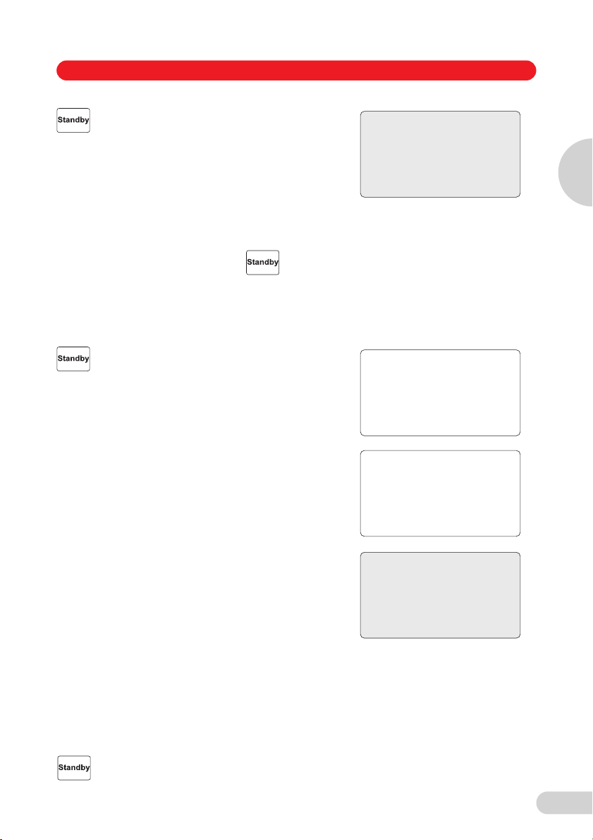
Standby
in the case of a brief interruption
When key is pressed briefly:
The device switches to the Standby mode without
deairing. The illumination of the display switches off.
"STANDBY" appears in the display with the suffix
"Supply pressure = rxyz" as a code for system pressure
ps being maintained.
Application:
For temporary interruptions or use of as a Reset
function.
When key is pressed again:
The device is reactivated and runs through a warm-up
routine. This lasts approximately one minute.
Standby
with deairing of pressure accumulator
Hold down the key (approx. 2 seconds; the display
moves to "STANDBY"):
The device switches to the Standby mode. The valve
system is completely deaired, the illumination of the
display switches off.
In addition to WAIT, the display also instructs that the
compressed air supply is to be separated from the
device. At the same time, some of the system pressure is
released in order to support this instruction.
A noise can be heard at this stage.
"STANDBY" appears in the display with the note
"Supply pressure = x" (x ~ 0).
Application:
For correct shutdown, with deairing of the entire pressure
system in the event of longer periods of non-use or
standstill (weekend or storage) with subsequent
switch-off using the mains switch.
Press the key again:
The device is reactivated and runs through the warm-up
routine.
STANDBY
3
Supply pressure 6789
Mode of operation
Hold standby
to exhaust
WAIT
Close supply pressure
Supply pressure 5261
STANDBY
Supply pressure 0
Reset
To reset the device to the initial mode by pressing the
key briefly or via the mains switch.
65
Page 18

3 Mode of operation
3.2 Hand control / foot control
3
Mode of operation
The functions of the hand / foot control correspond to the
functions of the and keys on the FemtoJet® express.
The function of the foot control corresponds to the
key.
66
Page 19

3 Mode of operation
3.3 Connecting the capillary holder
Universal capillary holder
The universal capillary holder is used to locate the injection capillaries. Prefabricated Eppendorf
Femtotips® / Femtotips® II (6) are screwed into the universal capillary holder using the adapter
(5). To do so, the adapter for Femtotips® (5) is first screwed into the front rotatable knurled
screw (4) and then the Femtotip® / Femtotip® II is attached. If self-pulled capillaries are to be
attached, the grip head 0 (7) needs to be screwed loosely into the front rotatable knurled screw
(4). The self-pulled capillary is pushed into the front opening of the grip head through the two
O-rings and fixed in position by tightening the grip head.
2
1
Universal capillary holder
1 Tube connection
2 Rear knurled screw
3 Tension piece
4 Front knurled screw, rotatable
5 Adapter for Femtotips
6 Femtotip® / Femtotip® II
7 Grip head 0, plastic, with two O-rings and sealing washers
3456
7
®
(microcapillaries for microinjection)
3
Mode of operation
Connecting the universal capillary holder
The two-meter-long injection tube is connected to the switched on FemtoJet® express (1) via
the bayonet joint (2). The pressure tube (3) is screwed to the rear knurled screw (4) of the
universal capillary holder. Femtotips® / Femtotips® II are fitted at the front end of the universal
capillary holder (5) or independently-manufactured capillaries are clamped with the aid of the
appropriate grip head.
2
1
34 5
67
Page 20

3 Mode of operation
Other accessories
3
3.4 Information on working practices
The following pressures can be used:
Mode of operation
Name Pressure range Comments
Grip head 0,
incl. 2 sets of O-rings and sealing washers.
Using grip head 0 supplied, capillaries with an outer diameter of 1.0 mm
to 1.1 mm can be used. In the case of outer diameters which differ from
these measurements, the relevant grip heads can be ordered as
non-standard accessories for the universal capillary holder
(see Section 7, Ordering information). The transparent grip head allows
the user to visually monitor the position of the capillary.
Compensation
pressure pc
Injection pressure p
Clean pressure maximum
Constant working
pressure pw
System pressure p
[supply pressure]
The usual values for the permanent compensation pressure P
for Femtotips® and similar capillaries. The FemtoJet® express shows good, constant values
within this range Immediately after the device is switched on and maintains the balance between undesired absorption of medium on the one hand and excessive loss of the liquid to be
injected on the other hand.
Quite low Pc values are sometimes advisable for special applications (e.g. capillaries with an
interior diameter of 5 µm and greater)! In order to be able to also work precisely and efficiently
here, the FemtoJet® express should be switched on app. 60 to 90 minutes before beginning the
experiment to guarantee the correct thermal settings. A pressure setting below 5 hPa is not
possible. You may merely also set 0 hPa.
i
s
0; 5 – 6,000 hPa
0.00; 0.07 – 87.0 psi
0; 5 – 6,000 hPa
0.00; 0.07 – 87.0 psi
up to 7,000 hPa
maximum up to 102 psi
0; 5 – 6,000 hPa
0.00; 0.07 – 87.0 psi
maximum
up to 7,000 hPa
maximum up to 102 psi
Or up to 500 hPa less than the
system pressure p
Or up to 500 hPa less than the
system pressure p
Or up to 500 hPa less than the
system pressure p
Select Function 4 via the
key.
This is used directly for
.
are between 30 – 50 hPa
c
s
s
s
68
Page 21

3 Mode of operation
An internal self-calibration of 3 seconds for more precise adjustment of the pressure takes
place every 10 minutes. No injection is carried out during this time.
Injection can continue as usual following the self-calibration.
An already activated injection will be carried out by the FemtoJet express. The self-calibration
takes place afterward.
Message during the self-calibration on the display of the FemtoJet express:
3
WAIT
A brief signal sounds at the beginning and end of the
self calibration
If the FemtoJet express is connected with the InjectMan NI 2, the following message appears on
the display of the micromanipulator:
Warning 001
Check Injector and cable
calibration.
Press the joystick button again to repeat the injection.
Press joystick button
Self-calibration intervals:
– In the first hour after the machine is switched on: every 10 minutes.
– Afterwards: Every 30 min at pc < 30 hPa or every 15 min at pc > 30 hPa
following the last activation.
Mode of operation
69
Page 22

3 Mode of operation
3.4.1 Compensation pressure pc
The compensation pressure pc ensures that no medium flows into the capillary. Capillary forces
would make liquid flow out of the cell culture dish into the injection capillary and thus dilute the
injection material. To prevent this, a permanent compensation pressure pc is set. This should be
3
selected so that there is a permanent slight flow-out of liquid from the injection capillary. The
individual pressure level can be determined in a preliminary test. For example, a fluorescent dye
can be added to the capillary to enable outflow to be monitored directly. The pressure required
is heavily dependent on the surface tension and viscosity of the injection material. Experience
has shown that compensation pressures of between 30 hPa and 300 hPa (0.44 – 4.4 psi) are
appropriate values for ready-to-use Eppendorf Femtotips® injection capillaries.
Capillary suction
Compensation pressure p
c
Mode of operation
Hydrostatic pressure P
Pressure in the capillaries
3.4.2 Injection pressure p
Injection pressure pi is applied during the injection process. This pressure is generally higher
than the compensation pressure. In many cases, a pressure between 50 hPa and 500 hPa
(0.73 – 7.2 psi) is appropriate for Femtotips®. The volume injected is dependent on the injection
pressure and the injection time. The injection pressure must be greater than the internal
pressure of the cell into which injection should take place. However, if the cell or the cell nucleus
swell up during injection, the injection pressure is too high.
3.4.3 Injection time t
Injection time ti gives the period for which injection pressure pi is maintained. ti is usually
selected from a range between approx. 0.3 s and 1.5 s. The relevant factor for the injected
volume is the product of the injection pressure and the injection time.
Depending on the setting on the Eppendorf Micromanipulator which is connected, the injection
time ti is measured from the point at which the key is pressed. The injection pressure is
built up immediately, so it is already present
during the injection movement and during penetration of the cell. Once the end of injection time
has been reached, the device switches to compensation pressure pc. At the same time, the
micromanipulator is moved back into the working level. When "Injection at Z limit" is set,
measurement of the injection time ti does not begin until the Z limit has been reached. Once ti
has elapsed, the FemtoJet® switches back to pc and the micromanipulator moves back into its
starting position in the working level
i
i
hyd
70
Page 23

3 Mode of operation
3.4.4 Clean function
The Clean function is used to flush out blocked capillaries. The maximum available pressure is
applied to the outlet with the key. It is applied for as long as the key is pressed.
The maximum pressure of the FemtoJet® express is in the range of 7,000 hPa (102 psi) within
the range of the displayed system pressure. The value cannot be changed.
The pressure curve up to maximum pressure appears in the display in the form of a bar chart.
By pressing the key briefly, a lower pressure can also be obtained.
3.4.5 Manual or automatic injection
In the Manu operating mode, injection is performed for as long as the key or hand / foot
control is held down. The duration (ti) of injection is measured and shown in the display. In the
case of combination with an Eppendorf Micromanipulator, the injection movement is triggered.
In the Auto operating mode, the built-in timer facilitates a reproducible injection time.
The injection runs automatically for the duration of set time ti. It is triggered by the key or
the hand / foot control being pressed briefly. During injection, the Inject key is
inactive, i.e. pressing it again has no effect. In combination with an Eppendorf Micromanipulator, the automatic injection procedure can also be triggered from the operating panel of the
micromanipulator.
3.4.6 Constant pressure / constant working pressure
Using the Constant Pressure function, it is possible to select a higher pressure permanently if
required. This function is helpful when special injection techniques require either a high pressure
up to a maximum of 6,000 hPa (87 psi) or a permanent flow of injection solution
(see Section 3.7.5). Control accuracy drops in the pressure range from 2,000 – 6,000 hPa
(29 – 87 psi).
3
Mode of operation
71
Page 24

3 Mode of operation
3.5 The first injection
The following are available:
3
• Adherent cells in a Petri dish,
• Injection liquid (purified, e.g. by centrifugation),
• Femtotips
• Microloader,
• 0.5 – 10 µl pipette to take the Microloader,
• A universal capillary holder on the micromanipulator which has been preadjusted with a
Femtotip®.
Filling the Femtotips® with the Microloader:
Mode of operation
– Select function 0 "Capillary exchange" by pressing . Connect the pressure tube.
– Aspirate approximately 0.5 – 5.0 µl of centrifuged injection fluid with the Microloader
without touching the base of the vessel. Using the Microloader, fill the Femtotip® through
the rear opening, inserting the tip approximately up to the centre of the Femtotips
releasing the fluid there.
– Hold the Femtotip® vertically, loosen the cap by turning it and allow it to drop vertically.
– Screw the Femtotip® into the capillary holder.
– Complete Function 0 by pressing Compensation pressure is applied.
– Move the capillary into the cell medium (Petri dish) with the micro-manipulator.
– Focus the cells with the microscope, position the capillary slightly above the cells but do
not allow it to come into contact with the base of the Petri dish. Focus the capillary.
– Using the key, check that the capillary is not blocked. Either the fluid can be seen
flowing out or it is rendered visible by the fluorescent substance it entrains.
As a rule, any air bubbles present are blown out.
– Perform a sample injection using the preset parameters (e.g. pi ~ 150 hPa, ti ~ 0.5 s,
~ 50 hPa, corresponding to pi ~ 2.18 psi, ti ~ 0.5 s, pc ~ 0.73 psi). Injection can be
p
c
monitored visually when the cell size changes by approx. 5 % to 10 % or via fluorescence.
If required, adapt parameters p
®
/ Femtotips® II; other capillaries as an alternative
and/or ti.
i
®
and
72
Page 25

3 Mode of operation
3.6 Connecting an Eppendorf Micromanipulator
Connection to an Eppendorf Micromanipulator designed for automated injection is effected with
the 15-pin interface.
12 3 4 56
FemtoJet® express (rear) with all connection options, with InjectMan® NI 2
1 Foot control (optional) with Inject function
2 Hand control with Inject and Clean functions
3 FemtoJet® express
4 Micromanipulator InjectMan® NI 2
5 Connection socket of micromanipulator for Interface cable FemtoJet
6 Interface cable FemtoJet® express (accessories: InjectMan® NI 2)
7 Interface of FemtoJet® express to micromanipulator
7
3
Mode of operation
73
Page 26

3 Mode of operation
12 3 4 5 6
3
FemtoJet® express (rear) with all connection options, with power unit 5171 / InjectMan 5179
Mode of operation
1 Foot control (optional) with Inject function
2 Hand control with Inject and Clean functions
3 FemtoJet® express
4 Micromanipulator 5171 or InjectMan
5 Connection socket of micromanipulator for
Transmission cable 5246 ("Y cable")
6 Transmission cable 5246
(accessory for Micromanipulator 5171 and InjectMan®)
7 Interface cable 5171 (optional)
(Connection from FemtoJet® express to Transmission cable 5246 "Y cable")
8 Interface of FemtoJet® express to micromanipulator
8
7
®
74
Page 27

3 Mode of operation
3.7 Functions
The Function menu is called up using the key. One of seven functions is selected using
left-hand variable regulator pi.
The relevant functionality is assigned to the variable regulators in the bottom line of the display.
Exit the Function menu by pressing the key again.
In cases of error, pressure control is switched off from within the Function menu. Then exit the
Menu using the key.
Function 6, self-test, is described in Section 5, "Troubleshooting".
Function 5 is not planned for the FemtoJet® express.
3.7.1 Changing the capillaries
FUNC 0
Change capillary
Capillary may be
changed now
Turn pi to
select function
3.7.2 Setting the pressure unit
FUNC 1
Push Inject to select
Pressure Unit hPa PSI
Turn pi to
select function
FUNC 0
When this function is called up, the pressure tube is
deaired and any pressure present in the system is let out.
Once the capillary has been changed, exit the function
using the key or variable regulator p
pressure control will restart.
FUNC 1
The other pressure unit is selected using the key
and all pressure values are converted.
The pressure unit currently selected (in this case: hPa)
is underlined.
;
i
3
Mode of operation
3.7.3 Switching on/off the loudspeaker
FUNC 2
Push Inject to select
Beeper ON OFF
Turn pi to
select function
FUNC 2
Use the key to switch the loudspeaker on or off.
The currently selected setting (in this case: ON) is
underlined. Acoustic error messages are not emitted if the
setting is OFF.
75
Page 28

3 Mode of operation
3.7.4 Switching on/off the background illumination of the display
FUNC 3
Push Inject to select
3
Mode of operation
Illumination ON OFF
Turn pi to
select function
3.7.5 Constant pressure
FUNC 4
Continuous flow
INJECT = start
Turn pi to
select function
FUNC 3
Use the key to switch the illumination on or off. The
currently selected setting (in this case: ON) is underlined.
In the normal operating mode, illumination switches off after
three minutes if no operating control has been actuated.
When an operating control is actuated, the illumination
lights up again.
FUNC 4
This function can be used to apply a constant working
pressure pw in the range from 5 to 6,000 hPa (87.0 psi) at
the pressure outlet. The pressure unit psi can also be used.
FUNC 4
Continuous flow
pw= 50 hPa
Supply pressure 5261
Turn pi to pw[hPa]
select function 50
76
The working pressure pw is set with the right-hand variable
regulator (p
characters. The actual value is shown in the bottom right of
the display.
The Clean function can be activated. The pressure of the
Clean function is shown in the bottom right of the display in
the form of pw.
), the specified value is shown in large
c
Page 29

4 Cleaning and Service
4.1 Cleaning
Before cleaning the FemtoJet® express disconnect the plug.
Ensure that no fluids enter into the inside of the injector in order to avoid short-circuits in the
electrical installation as well as corrosion.
Wipe painted parts and aluminum surfaces using a cloth and mild detergent and then with a dry
cloth.
Warning: Do not use any corrosive, solvent or abrasive detergents or polishes.
4.2 Disinfection
Clean the FemtoJet
Wipe every part of the FemtoJet® express, including accessories and connector cables, with
disinfectant like alcohol (ethanol, isopropanol) or alcoholic disinfection media.
Spray disinfection is not advisable, as disinfectants can enter into the microinjector.
The disinfection method used must comply with current disinfection
regulations and guidelines.
4.3 Decontamination prior to shipping
If the device is to be inspected, repaired or calibrated by the service partners of the
Eppendorf AG, it must be free of hazardous substances and clean!
A decontamination certificate must accompany the FemtoJet
A printed form ("Decontamination certificate for return of goods" and general instructions for
decontamination are available at our www.eppendorf.com homepage.
The serial number of the device must be entered in the decontamination certificate.
®
express before disinfecting.
®
express.
4
Cleaning and Service
4.4 Service
Warranty or service is taken over by the supplier or the service partner of the
Eppendorf AG.
77
Page 30

5 Troubleshooting
5.1 Potential errors
– Pressure loss due to capillary not fitted with capillary holder connected.
Solution: Connect the capillary or select Function 0,
5
– Capillary is blocked.
Solution: Press the key for long enough.
Change capillary via the key and variable regulator pi.
Change capillary.
Purify injection fluid (e.g. by means of centrifugation).
– System pressure ps (or external pressure) sinks to
less than 4,000 hPa (58 PSI). This is represented by
Troubleshooting
the instruction avove the entry Supply pressure in the
display.
If an injection or cleaning is activated in this status,
this will trigger Warning 1 (Chapter 5.2).
– Valve rattles
Solution: Connect tube to filled capillary.
Pressure control is designed for the tube connected.
– No communication with the micromanipulator.
Solution: Check cables and connections.
AUTO n= 0
pi= 150 hPa
Apply supply pressure
Supply pressure 3999
pi[hPa] ti[s] pc[hPa]
150 0.2 50
78
Page 31

5 Troubleshooting
5.1.1 Self-test
FUNC 6
Self-Test
INJECT = Complete
CLEAN = Leak only
Turn pi to
select function
FUNC 6
The FemtoJet® is checked for leaks in the self-test.
This self-test can also be used if a leak is suspected.
The test runs automatically.
The pressure tube must be connected to a closed capillary
(e.g. melted closed or filled) for the pressure control to work
properly.
5
Troubleshooting
FUNC 6
Self-Test
Ps leak _____ _____ hPa
Pw leak _____ _____ hPa
Injection _____ _____ hPa
ps=7000 pw= 18 hPa
FUNC 6
Self-Test
Ps leak _____ _____ hPa
Pw leak _____ _____ hPa
ps=7000 pw= 18 hPa
key: Complete self-test
– In the case of two different pressures, checks for leaks
in the pressure accumulator (ps) and for the internal
tightness of the valves.
– Checks for leaks in the area of working pressure (pw)
in the case of two different pressures.
– Checks behavior during injection
at different pressures (short continuous test).
If certain values are outside the specified range, an error
message is emitted. If this recurs, inform Service.
key: Self-test to search for leaks
– Checks for leaks in the pressure accumulator (p
) in the
s
case of two different pressures, as well as for inner
tightness of the valves.
– Checks for leaks in the area of working pressure (pw) in
the case of two different pressures.
If certain values are outside the specified range, an error
message is emitted. If this recurs, inform Service.
79
Page 32

5 Troubleshooting
5.2 Warnings
As a rule, warnings are emitted if certain operating conditions are not (yet) reached or if an
action is not possible.
5
Acknowledge the warning with the key and the unit will return to normal status.
INJECT = Continue
Troubleshooting
WARNING 002
Check capillary
e.g. broken/missing ?
Warning 2
Compensation pressure cannot be maintained.
Possible cause:
Capillary or capillary holder not attached or only connected
loosely.
Solution:
Check all connections and tighten.
Activate Function 0 to change the capillary and when the
capillary holder is open.
WARNING 003
Switch on manipulator
or disconnect cable
INJECT = Continue
WARNING 004 4133
Supply pressure
is instable
please switch off/on
INJECT = Continue
Warning 3
Micromanipulator does not react.
A micromanipulator is connected but does not react to a
start pulse from the FemtoJet
®
express.
Possible cause:
Micromanipulator is switched off.
INJECT function on manipulator is not released.
No limit is set on the micromanipulator.
In the INJECT function on the micromanipulator,
synchronization is set to limit (SYNC = LIMIT).
Solution:
Switch on the micromanipulator and make it operational.
Disconnect the cable to micromanipulator.
With SYNC = LIMIT, trigger semi-automatic injection via the
micromanipulator only.
Warning 4
The attached external pressure has changed greatly. When
switched on, the automatic valve adjustment took place for
a different pressure (displayed value to upper right).
Solution:
Switch device off and on again. The automatic valve adjustment will be carried out with the present pressure.
Note:
This warning is issued only once. Pressing the
key will remove the error message. It will
generally be possible to continue work. However, optimal
valve regulation should not be anticipated.
80
Page 33

5 Troubleshooting
WARNING 005
Supply pressure
is too low
INJECT = Continue
WARNING 006 4202
Supply pressure
is lower than +500 hPa
INJECT = Continue
Warning 5
External pressure is insufficient.
The minimum supply pressure required for an injection or
the Clean function was not present when the function was
triggered.
Possible cause:
There is no external pressure supply, it is not connected or
supplies too little pressure (< 4,000 hPa).
Solution:
Connect external pressure supply and select the external
pressure within the range from 4,000 – 8,000 hPa.
Warning 6
Injection pressure (or compensation pressure) is close top
the external pressure.
An injection pressure is required that is not at least
500 hPa below the external pressure (value displayed to
the upper right).
Possible cause:
External pressure is set too low.
Injection pressure has been (accidentally) set too high.
Injection pressure has been intentionally so set.
Solution:
Increase external pressure or reduce injection pressure.
Note:
This warning is issued only once. Pressing the
key will remove the error message. It will
generally be possible to continue work. However, optimal
valve regulation should not be anticipated.
5
Troubleshooting
WARNING 007
Supply pressure
is too low
INJECT = Continue
Warning 7
External pressure is insufficient.
Possible cause:
There is no external pressure supply, it is not connected or
supplies too little pressure (< 4,000 hPa).
Solution:
Connect external pressure supply and select the external
pressure within the range from 4,000 – 8,000 hPa.
81
Page 34

5 Troubleshooting
5.3 Error messages
Error messages are emitted if certain operating conditions are not reached or the device records
a deviation from specified conditions.
5
Acknowledge the error message with the key and the unit will return to normal status.
The measures described under “Solution” should be carried out. If the error message recurs
after acknowledgement with the key, inform Service.
Some errors can only occur in connection with the FemtoJet® 5247 device (with internal
compressor).
Supply pressure
Troubleshooting
cannot be reached
INJECT = Continue
Supply pressure is
INJECT = Continue
ERROR 010
ERROR 011
too high
Error 10
Supply pressure cannot be reached
The compressor runs without the maximum supply
pressure being reached.
Possible cause:
High compensation pressure when the capillary holder is
not attached or is poorly attached.
Technical cause:
Compressor does not start up. Leak in compressor or
pressure accumulator.
Solution:
Check the capillary holder and tube for leaks or tighten up
the tube connections.
Service.
Error 11
Supply pressure is too high
Supply pressure has exceeded the maximum permissible
supply pressure.
Possible cause:
Internal pressure limiter is defective.
Supply pressure is not relieved by the relevant standby
function.
Technical defect.
Solution:
Service.
Switch off using the key (hold down for approximately two seconds).
82
Page 35

5 Troubleshooting
ERROR 012
Supply pressure
does not fall
INJECT = Continue
ERROR 013
Supply pressure
does not raise
INJECT = Continue
ERROR 014
Supply pressure
leak is too high
INJECT = Continue
ERROR 015
Supply pressure
leak is too high
INJECT = Continue
ERROR 016
Valve 1 pressure
leak is too high
INJECT = Continue
Error 12
Supply pressure does not drop far enough
Possible cause: Technical defect
Solution: Service
Error 13
Supply pressure does not rise
Possible cause: Technical defect
Solution: Service
Error 14
Massive leak in pressure accumulator
Possible cause: Technical defect
Solution: Service
Error 15
Leak in pressure accumulator
Possible cause: Technical defect
Solution: Service
Error 16
Leak through Valve V1 is too large
Possible cause: Technical defect
Solution: Service
5
Troubleshooting
ERROR 020
Working pressure
cannot be reached
INJECT = Continue
Error 20
Working pressure has not been reached
Compressor runs without supply pressure being reached
within a specific time.
Possible cause:
Capillary holder not attached or poorly attached.
(Broken) capillary with large opening.
Technical defect.
Solution:
Check the capillary. Check the capillary holder and tube for
leaks or tighten up the tube connections.
Service.
83
Page 36

5 Troubleshooting
5
Troubleshooting
INJECT = Continue
Compensation pressure
INJECT = Continue
INJECT = Continue
ERROR 021
Inject pressure
cannot be reached
ERROR 022
cannot be reached
ERROR 023
Inject pressure
overflow too large
Error 21
Injection pressure has not been reached
Possible cause:
Capillary holder not attached or poorly attached.
(Broken) capillary with large opening.
Technical defect.
Solution:
Check capillary. Check capillary holder and tube for leaks or
tighten up tube connections.
Service.
Error 22
Compensation pressure has not been reached
Possible cause:
Capillary holder not attached or poorly attached.
(Broken) capillary with large opening.
Technical defect.
Solution:
Check capillary. Check capillary holder and tube for leaks or
tighten up tube connections.
Service.
Error 23
Increase in working pressure is smaller than required
Possible cause: Technical defect
Solution: Service
INJECT = Continue
INJECT = Continue
84
ERROR 024
Working pressure
does not rise
ERROR 025
Working pressure
does not fall
Error 24
No increase in working pressure
Possible cause: Technical defect
Solution: Service
Error 25
No drop in working pressure
Possible cause: Technical defect
Solution: Service
Page 37

5 Troubleshooting
ERROR 026
Working pressure
leak is too high
INJECT = Continue
ERROR 027
Working pressure
leak is too high
INJECT = Continue
ERROR 028
Working pressure
leak is too high
INJECT = Continue
Error 26
Working pressure leak rate is too high
Possible cause:
Capillary holder not attached or poorly attached.
(Broken) capillary with large opening.
Technical defect.
Solution:
Check capillary. Check capillary holder and tube for leaks or
tighten up tube connections.
Service.
Error 27
Working pressure leak rate is too high
Possible cause:
Capillary holder not attached or poorly attached.
(Broken) capillary with large opening.
Technical defect.
Solution:
Check capillary. Check capillary holder and tube for leaks or
tighten up tube connections.
Service.
Error 28
Working pressure leak rate is too high
Possible cause:
Capillary holder not attached or poorly attached.
(Broken) capillary with large opening.
Technical defect.
Solution:
Check capillary. Check capillary holder and tube for leaks or
tighten up tube connections.
Service.
5
Troubleshooting
ERROR 030
Sensoroffset supply
is too low
INJECT = Continue
Error 30
Sensor offset supply pressure is too low
Possible cause: Technical defect
Solution: Service
85
Page 38

5 Troubleshooting
5
INJECT = Continue
INJECT = Continue
Troubleshooting
INJECT = Continue
INJECT = Continue
INJECT = Continue
ERROR 031
Sensoroffset supply
is too high
ERROR 032
Sensoroffset work
is too low
ERROR 033
Sensoroffset work
is too high
ERROR 034
Valve 1 offset
is too low
ERROR 035
Valve 1 offset
is too high
Error 31
Sensor offset supply pressure is too high
Possible cause: Technical defect
Solution: Service
Error 32
Sensor offset working pressure is too low
Possible cause: Technical defect
Solution: Service
Error 33
Sensor offset working pressure is too high
Possible cause: Technical defect
Solution: Service
Error 34
Valve 1 offset is too low
Possible cause: Technical defect
Solution: Service
Error 35
Valve 1 offset is too high
Possible cause: Technical defect
Solution: Service
INJECT = Continue
86
ERROR 036
Valve 2 offset
is too low
Error 36
Valve 2 offset is too low
Possible cause: Technical defect
Solution: Service
Page 39

5 Troubleshooting
ERROR 037
Valve 2 offset
is too high
INJECT = Continue
ERROR 040
Self-Calibration
is missing
INJECT = Continue
ERROR 041
Fullscale Calibration
is missing
INJECT = Continue
Error 37
Valve 2 offset is too high
Possible cause: Technical defect
Solution: Service
Error 40
Self-calibration is missing
Possible cause: Technical defect
Solution: Service
Error 41
Full-scale calibration is missing
Possible cause: Technical defect
Solution: Service
5
Troubleshooting
87
Page 40

6 Technical data
Voltage/Frequency: 100 V – 240 V ± 10 %, 50 – 60 Hz
Set voltage: adapts automatically
Fuse for 100 – 240 V: T1.0 A, 250 V (2 pcs.)
6
Leistungsaufnahme: 20 W
Max. current consumption: < 0.5 A
Protection class: I
Overvoltage category: II (IEC 61010-1)
Pollution degree: 2 (IEC 664)
Ambient temperature: 15 °C – 35 °C
Technical data
Ambient relative humidity: max. 70 %
Weight: 4.5 kg
Dimensions: Width: 220 mm
Minimum external pressure
to be supplied: > 4,000 hPa ( 60 PSI), constant
Maximum external pressure
to be supplied: < 8,000 hPa (120 PSI), constant
Injection time t
Injection pressure pi: 0; 5 – max. 6 000 hPa (87 PSI),
Compensation pressure pc: 0; 5 – max. 6 000 hPa (87 PSI),
Regulating accuracy: 1 % of value set in each case,
Clean rinsing pressure: max. approx. 7,000 hPa (102 psi)
RS 232 computer Baud rate: 9,600
interface: Start bit: 1
Depth: 170 mm
Height: 280 mm
: 0.0 – 99.9 s
i
in 0.1 s increments
in 1 hPa (0.01 – 0.02 psi) increments
in 1 hPa (0.01 – 0.02 psi) increments
at least ± 1 hPa
Data bits: 8
Parity: non
Stopbit: 2
Technical specifications subject to change!
88
Page 41

7 Ordering information
Order no.
FemtoJet® express
100 V – 240 V ± 10 %, 50 – 60 Hz
Fully programmable microinjector incl. connection for external
pressure supply. For injection of smallest amounts of liquid into living cells.
Delivery package:
1 FemtoJet
1 Power cable
1 Universal capillary holder
1 Pressure tube, 2.5 m, incl. connection for external pressure supply,
incl. coupling G 1/4-inch
1 Injection tube, 2 m
1 Hand control for remote control
10 Femtotips® / Femtotips® II (injection capillaries)
10 Microloader
1 Operating Manual
Version Europe 5248 000.017
Version USA and Canada 5248 000.050
Version UK / Hongkong 5248 000.033
Version Japan 5248 000.041
Version Australia 5248 000.076
Version China 5248 000.084
®
express
5248 200.008
5247 617.002
7
Ordering information
Accessories (not standard)
Foot control FemtoJet
Interface cable PC
for control and for program updates
Interface cable FemtoJet®
for connection to the InjectMan® NI 2
Interface cable 5171
for connection to the micromanipulator 5171 or InjectMan® 5179
20 Femtotips
20 Femtotips® II 5242 957.000
200 Microloader 5242 956.003
Filling Stand 5242 009.012
1 Injection tube, 2 m, for universal capillary holder 5246 164.004
Universal capillary holder
(incl. grip head 0, adapter for Femtotips® and spare O-rings)
®
®
5247 623.002
5325 620.007
5181 070.015
5247 622.006
5242 952.008
5176 190.002
89
Page 42

7 Ordering information
Grip head 0 for universal capillary holder;
for microcapillaries with an outer diameter of 1.0 to 1.1 mm
7
Grip head 1 for universal capillary holder;
for microcapillaries with an outer diameter of 1.2 to 1.3 mm
Grip head 2 for universal capillary holder;
for microcapillaries with an outer diameter of 1.4 to 1.5 mm
Grip head 3 for universal capillary holder
for microcapillaries with an outer diameter of 0.7 to 0.9 mm
O-ring set
for grip heads 0 to 3 with extraction tool
Service kit
for grip head and capillary holder, consisting of O-ring set,
adapter for Femtotip
Ordering information
Micromanipulation
InjectMan® NI 2
Micromanipulator for automatic injection in adherent cells
in combination with FemtoJet
Version Europe 5181 000.017
Version USA and Canada 5181 000.025
Version UK / Hongkong 5181 000.033
Version Japan 5181 000.041
Version Australia 5181 000.076
Version China 5181 000.084
®
and clamping piece (for 5171, 5179)
®
Order no.
5176 210.003
5176 212.006
5176 214.009
5176 207.002
5176 196.000
5176 195.004
®
TransferMan
Proportional micromanipulator for microinjection
in suspension cells
Version Europe 5188 000.012
Version USA and Canada 5188 000.020
Version UK / Hongkong 5188 000.039
Version Japan 5188 000.047
Version Australia 5188 000.071
Version China 5188 000.080
90
NK 2
Page 43

7 Ordering information
Order no.
PatchMan NP 2
Micromanipulator for electrophysiology or other applications
Version Europe 5183 000.014
Version USA and Canada 5183 000.022
Version UK / Hongkong 5183 000.030
Version Japan 5183 000.049
Version Australia 5183 000.073
Version China 5183 000.081
7
Ordering information
Transmission cable 5246
"Y cable" for connection with the interface cable 5171
Foot control for microinjection,
connectable to transmission cable 5246 "Y cable"
5246 621.006
5211 058.007
91
Page 44

7a Ordering information for North America
FemtoJet® express
100 V – 240 V ± 10 %, 50 – 60 Hz
7a
Fully programmable microinjector incl. connection for external pressure
supply. For injection of smallest amounts of liquid into living cells.
Delivery package:
1 FemtoJet
1 Power cable
1 Universal capillary holder
1 Pressure tube, 2.5 m, incl. connection for external pressure supply,
incl. coupling G 1/4-inch
1 Injection tube, 2 m
1 Hand control for remote control
10 Femtotips® / Femtotips® II (injection capillaries)
10 Microloader
1 Operating Manual
Version USA and Canada 920010521
Version Europe 5248 000.017
Version UK / Hongkong 5248 000.033
Version Japan 5248 000.041
Version Australia 5248 000.076
Ordering information for North America
Version China 5248 000.084
®
express
Order no.
920011993
920010512
Accessories (not standard)
Foot control FemtoJet
Interface cable PC
for control and for program updates
Interface cable FemtoJet®
for connection to the InjectMan® NI 2
Interface cable 5171
for connection to the micromanipulator 5171 or InjectMan® 5179
20 Femtotips
20 Femtotips® II 930000043
200 Microloader 930001007
Filling Stand 930000051
1 Injection tube, 2 m, for universal capillary holder 920007431
Universal capillary holder
(incl. grip head 0, adapter for Femtotips® and spare O-rings)
92
®
®
920005098
015160501
920005845
5247 622.006
930000035
920007392
Page 45

7a Ordering information for North America
Order no.
Grip head 0 for universal capillary holder;
for microcapillaries with an outer diameter of 1.0 to 1.1 mm
Grip head 1 for universal capillary holder;
for microcapillaries with an outer diameter of 1.2 to 1.3 mm
Grip head 2 for universal capillary holder;
for microcapillaries with an outer diameter of 1.4 to 1.5 mm
Grip head 3 for universal capillary holder
for microcapillaries with an outer diameter of 0.7 to 0.9 mm
O-ring set
for grip heads 0 to 3 with extraction tool
Service kit
for grip head and capillary holder, consisting of O-ring set,
adapter for Femtotip
Micromanipulation
InjectMan® NI 2
Micromanipulator for automatic injection in adherent cells
in combination with FemtoJet
Version USA and Canada 920000029
Version Europe 5181 000.017
Version UK / Hongkong 5181 000.033
Version Japan 5181 000.041
Version Australia 5181 000.076
Version China 5181 000.084
®
and clamping piece (for 5171, 5179)
®
920007414
920007708
920007716
920007406
920005870
920005888
7a
Ordering information for North America
®
TransferMan
Proportional micromanipulator for microinjection
in suspension cells
Version USA and Canada 920000011
Version Europe 5188 000.012
Version UK / Hongkong 5188 000.039
Version Japan 5188 000.047
Version Australia 5188 000.071
Version China 5188 000.080
NK 2
93
Page 46

7a
7a Ordering information for North America
Order no.
PatchMan NP 2
Micromanipulator for electrophysiology or other applications
Version USA and Canada 920000037
Version Europe 5183 000.014
Version UK / Hongkong 5183 000.030
Version Japan 5183 000.049
Version Australia 5183 000.073
Version China 5183 000.081
Transmission cable 5246
"Y cable" for connection with the interface cable 5171
Foot control for microinjection,
connectable to transmission cable 5246 "Y cable"
Ordering information for North America
920012043
920005047
94
Page 47

8 Index
A
Adapter for Femtotips 67
Anschluss
Micromanipulator 73
Universalkapillarenhalters 67
Application 53
automatische Injektion 71
B
Bedienung über den Computer 97
C
Clean 57
function 71
pressure 69
Cleaning 77
Commands 97
Compensation pressure 55, 62
Compressor 82, 84
D
Device
description 60
rear of 60
Disinfection 77
Display 56, 58, 62
G
Grip head 67, 68
H
Hand control 73
I
Information on working practices 69
Injection
automatic 63, 71
first 72
manual 63
movement 70
parameters 62
pressure pi 55, 69
time ti 55, 70
interface 73
K
Key
Auto / Manu 58, 64
Clean 58, 64
Count 58, 64
Inject 58, 63
Menu 58, 64
Standby 58, 65
Keypad 56, 63
8
Index
E
Error 82
messages 82
potential 78
F
Foot control 55, 57, 60
Function 58
Functions 75
keys 66
menu 64
L
Loudspeaker 75
M
mains switch 60
Manuelle Injektion 71
Mode of operation 62
O
Ordering information 89
Overview 56
95
Page 48

8 Index
8
Index
P
Pressure
pressure accumulator 65
supply, external 61
tube 57, 67
Q
Query 97
R
Reset 58, 65
function 65
S
Safety precautions 53
Self-test 79
checks for leaks 79
complete 79
Short description 58
Standby with deairing 65
Startup 60
Switch
off 61
on 61
System pressure 62, 78
U
Universal capillary holder 67
V
Variable regulator 55, 56, 59, 62, 64, 75
T
Taste
Clean 58
Count 58
Standby 58
Technical data 88
Tension piece 67
Troubleshooting 78
Tube connection 56, 59
96
Page 49

9 Appendix A
Operation via a computer
Certain commands and queries (Section 6.2) can be transmitted to the unit using the optional
cable / PC interface.
A.1 Description of interface
®
A computer can be connected to the remote control of the FemtoJet
two RS 232 interfaces. Parameters can be entered or read out via the computer.
The computer is connected by the special cable / PC interface cable.
The computer to be connected must comply with EN 60950 / UL 1950 standards.
The serial interface of the computer should be set to the following transmission parameters:
Baud rate: 9,600
Start bit: 1
Dat bits: 8
Parity: non
Stop bit: 2
Only ASCII symbols (incl. CR/LF) which can be represented are transmitted. Therefore a
terminal program, for example, is suitable for remote control.
A.2 Commands and queries
The commands to be sent are defined with the following structure:
Commands to enter parameters: "Cxxx=ssssssssss"
Commands to execute and to read out parameters: "Cxxx"
C: Command
xxx: Code for the executing command
=: Separation for the following input parameters
ssssssssss: Input parameters
In response to any command, the device provides a symbol string of a similar structure:
"Axxx" for answers without output parameter
"Axxx=rrrrrrrrrr" for responses with output parameter
A: Answer
express via one of the
9
Appendix A
If the command is faulty, an error message is returned instead of the answer:
"ERR=eee"
ERR: Error
=: Separation
eee: Error number
Lower and upper case letters can be used.
97
Page 50

9 Appendix A
9
Appendix A
Command to enter
parameters
[C]
Short acoustic signal 003 1 – 254 Number of signals
Long acoustic signal 004 1 – 254 Number of signals
Automatic injection (inject at ti) 010 0; 1 – 999 Injection time in 1/10 seconds
Set injection counter n to 0 012 – – – No parameter input
Perform Clean 013 1 – 100 Time in 1/10 seconds
Execute Standby 014 0 or 1 0 = short
Switch acoustic signal on/off 040 0 or 1 Status:
Set pressure unit 041 0 or 1 Unit:
Set injection time t
Set compensation
pressure pc
Set injection pressure pi 044 0; 5 – 6,000 / 87 Pressure in hPa/psi
Set background illumination 045 0 or 1 0 = off
Dewater 046 – – – No parameter input
042 1 – 999 Injection time
i
Code
[xxx]
043 0; 5 – 6,000 / 87 Pressure in hPa/psi
Input
parameter
[ssssssssss]
Meaning of
input parameters
0: injection time set on the
FemtoJet
1 = long
0 = off / 1 = on
0 = hPa / 1 = psi
in 1/10 seconds
1 = on
®
98
Page 51

9 Appendix A
Command to read out
parameters
Query program version 101 Versions number x.xx
Query bleeper 150 Status:
Query pressure unit 151 Unit:
Query injection time ti 152 Injection time
Query compensation pressure pc 153 Pressure in hPa /psi 0 – 6,000 / 87
Query injection pressure pi 154 Pressure in hPa /psi 0 – 6,000 / 87
Query background illumination 155 Status:
Error no. for incorrect
operating construction
ERR = [eee]
060 The first character is not
061 The 2nd to 4th character
062 The 5th character is not =. Check entry parameters.
063 The parameter is not within
064 The command is not known. Check entry parameters.
Code
[C]
[xxx]
Cause Solution
a c or C.
is not a digit.
the permitted range.
Significance of
output parameter
0 = off / 1 = on
0 = hPa / 1 = psi
in 1/10 seconds
0 = off / 1 = on
Output parameter
[A]
0 or 1
0 or 1
1 – 999
0 or 1
Check entry parameters.
Change entry.
Check entry parameters.
Change entry.
Change entry.
Check entry parameters.
Change entry.
Change entry.
[rrrrrrrrrr]
9
Appendix A
99
Page 52

9 Appendix A
9
Appendix A
Other error numbers as well as the error cause and solution are described in Section 5,
"Troubleshooting". During remote control, no error texts appear in the FemtoJet® express
display.
Error no. during execution
ERR = [eee]
070 FemtoJet
071 FemtoJet® express is not
072 The command is not
073 This command cannot be
074 The connected micro-
Cause Solution
®
express is not
in routine mode.
ready.
finished within the
scheduled time.
executed at the moment,
because of insufficient
storage pressure.
See: Warning 001
manipulator did not
respond.
See: Warning 003
Check FemtoJet® express.
Bring FemtoJet® express into
routine operation.
Eliminate error.
Check FemtoJet® express or
micromanipulator.
As necessary, wait or eliminate
error.
Check FemtoJet® express or
micromanipulator.
Eliminate error.
Check FemtoJet® express.
Eliminate error.
Check micromanipulator.
Eliminate error.
100
Page 53

Page 54

Page 55

Eppendorf Offices
SPAIN
SWITZERLAND
UNITED KINGDOM
USA
OTHER COUNTRIES
ASEAN
Eppendorf AG
Regional Office in Malaysia
Tel. +60 3 8023 2769
Fax +60 3 8023 3720
E-Mail: eppendorf@eppendorf.com.my
Internet: www.eppendorf.com.my
AUSTRALIA / NEW ZEALAND
Eppendorf South Pacific Pty. Ltd.
Tel. +61 2 9889 5000
Fax +61 2 9889 5111
E-mail: Info@eppendorf.com.au
Internet: www.eppendorf.com.au
AUSTRIA
Eppendorf AG
c/o Schott Austria
Tel. +43 1 29017560
Fax +43 1 290175620
E-Mail: gilch.p@eppendorf.de
Internet: www.eppendorf.com
BRAZIL
Eppendorf do Brasil Ltda.
Tel. +55 11 30 95 93 44
Fax +55 11 30 95 93 40
E-Mail: eppendorf@eppendorf.com.br
Internet: www.eppendorf.com.br
CANADA
Eppendorf Canada Ltd.
Tel. +1 905 826 5525
Fax +1 905 826 5424
E-Mail: canada@eppendorf.com
Internet: www.eppendorf.com
CHINA
Eppendorf AG
Tel. +86 21 68760880
Fax +86 21 50815371
E-Mail: market.info@eppendorf.cn
Internet: www.eppendorf.cn
FRANCE
EPPENDORF FRANCE S.A.R.L.
Tel. +33 1 30 15 67 40
Fax +33 1 30 15 67 45
E-Mail: eppendorf@eppendorf.fr
Internet: www.eppendorf.fr
GERMANY
Eppendorf Vertrieb
Deutschland GmbH
Tel. +49 2232 418-0
Fax +49 2232 418-155
E-Mail: vertrieb@eppendorf.de
Internet: www.eppendorf.de
INDIA
Eppendorf India Limited
Tel. +91 44 52111314
Fax +91 44 52187405
E-Mail: info@eppendorf.co.in
Internet: www.eppendorf.co.in
ITALY
Eppendorf s.r.l.
Tel. +390 2 55 404 1
Fax +390 2 58 013 438
E-Mail: eppendorf@eppendorf.it
Internet: www.eppendorf.it
JAPAN
Eppendorf Japan Co. Ltd.
Tel. +81 3 5825 2363
Fax +81 3 5825 2365
E-Mail: info@eppendorf.jp
Internet: www.eppendorf.jp
NORDIC
Eppendorf Nordic Aps
Tel. +45 70 22 2970
Fax +45 45 76 7370
E-Mail: nordic@eppendorf.dk
Internet: www.eppendorf.dk
Eppendorf Ibérica S.L.
Tel. +34 91 651 76 94
Fax +34 91 651 81 44
E-Mail: iberica@eppendorf.de
Internet: www.eppendorf.es
Vaudaux-Eppendorf AG
Tel. +41 61 482 1414
Fax +41 61 482 1419
E-Mail: vaudaux@vaudaux.ch
Internet: www.eppendorf.com
Eppendorf UK Limited
Tel. +44 1223 200 440
Fax +44 1223 200 441
E-Mail: sales@eppendorf.co.uk
Internet: www.eppendorf.co.uk
Eppendorf North America
Tel. +1 516 334 7500
Fax +1 516 334 7506
E-Mail: info@eppendorf.com
Internet: www.eppendorfna.com
see:
www.eppendorf.com/worldwide
Page 56

In touch with life
Your local distributor: www.eppendorf.com/worldwide
Eppendorf AG · 22331 Hamburg · Germany · Tel. +49 40 538 01-0 · Fax +49 40 538 01-556
E-Mail: eppendorf@eppendorf.com
Eppendorf North America, Inc. · One Cantiague Road, P.O. Box 1019 · Westbury, N.Y. 11590-0207 USA
Tel. +1 516 334 7500 · Toll free phone 800 645 3050 · Fax +1 516 334 7506 · E-Mail: info@eppendorf.com
Application Support
Europe, International: Tel. +49 1803 666 789 · E-Mail: support@eppendorf.com
North America: Tel. 800 645 3050 ext. 2258 · E-Mail: support_NA@eppendorf.com
Asia, Pacific: Tel. +603 8023 2769 · E-Mail: support_Asia@eppendorf.com
 Loading...