

Page 1
Instruction Manual
D103626X012
Fisherr 685 Piston Actuator
685 Piston Actuator
September 2014
Contents
Introduction 1.................................
Scope of Manual 1.............................
Description 1.................................
Specifications 2...............................
Educational Services 3.........................
Principle of Operation 3.........................
Installation 5..................................
Three-Way Valve Applications Note 6.............
Actuator Mounting 6..........................
Handwheel Operation 7.........................
Maintenance 8.................................
Actuator Removal 8...........................
Seal and O-ring Replacement 9..................
Parts Ordering 11...............................
Parts Kit 11....................................
Parts List 12...................................
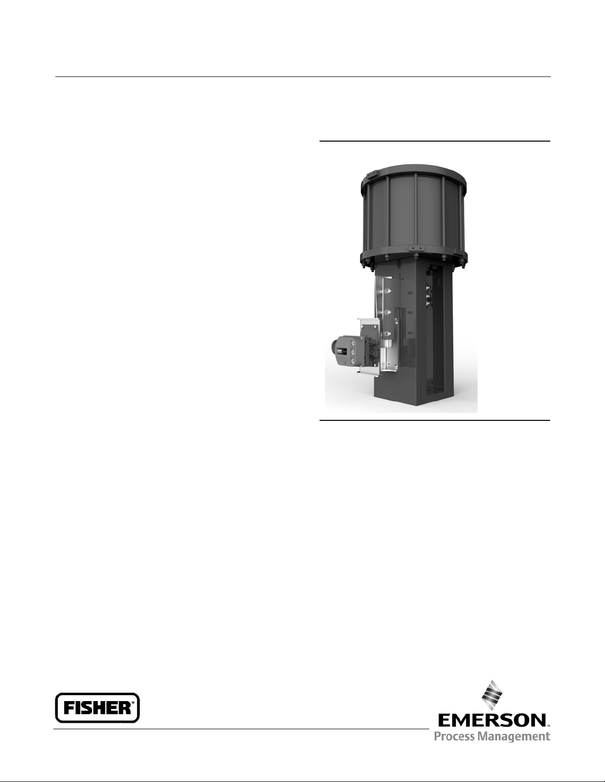
Figure 1. Fisher 685 Piston Actuator
X0922
Introduction
Scope of Manual
This instruction manual provides information on the installation, maintenance, and parts ordering for Fisher 685
piston actuators. Refer to separate instruction manuals for information regarding other equipment and accessories
used with these actuators.
Do not install, operate, or maintain a Fisher 685 actuator without being fully trained and qualified in valve, actuator,
and accessory installation, operation, and maintenance. To avoid personal injury or property damage, it is important
to carefully read, understand, and follow all the contents of this manual, including all safety cautions and warnings. If
you have any questions about these instructions, contact your Emerson Process Management sales office before
proceeding.
Description
The Fisher 685 is a double acting piston actuator that provides accurate, high thrust output for short to long travel
applications. This actuator is designed for use with a variety of medium to large Fisher sliding-stem control valves
including the easye™, FB, TBX, HP, EH, and 461.
www.Fisher.com
Page 2
685 Piston Actuator
September 2014
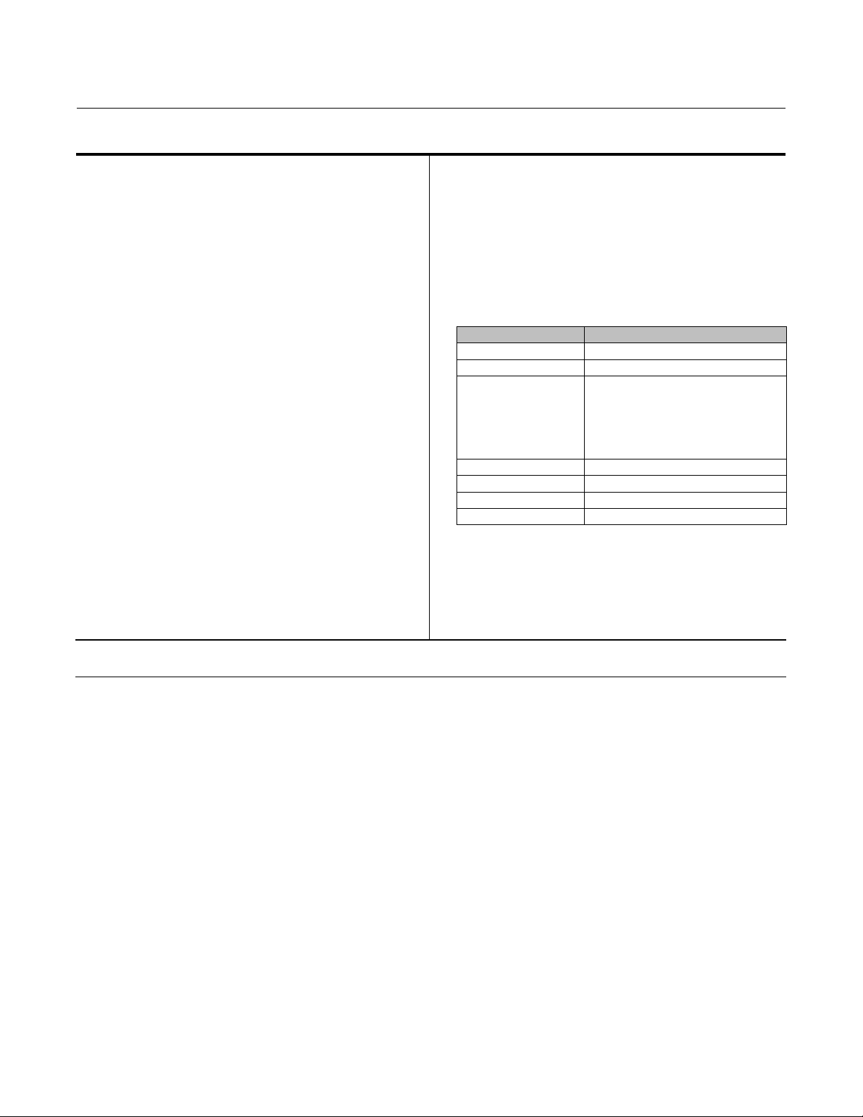
Table 1. Specifications
Instruction Manual
D103626X012
Operating Pressure
(1)
Minimum: 2.7 bar (40psig)
Maximum Allowable: 10.3 bar (150 psig)
Consult your Emerson Process Management sales
office for supply pressures under 2.7 bar (40 psi)
Pressure Connections
Standard: 3/4 NPT
Optional: 1and11/4 NPT
Instrument Mounting
Mounting kits are available for use with the FIELDVUE
(2)
Travel
25 mm (1 inch) through 610 mm (24 inch)
See table 2
Thrust Capabilities
See table 3
Piston Diameter and Area
(2)
DVC6200 series positioner
Construction Materials
PART MATERIAL
Yoke ASTM A36 (steel)
Piston ASTM A36 (steel)
Cylinder 305 to 559 mm (12 to 22 inch) Cylinder:
Available in 51 mm (2 inch) increments between 305
mm (12 inch) and 660 mm (26 inch)
See table 2
Operative Temperature Limits
Standard: 40 to 93_C(40 to 200_F)
Low Temperature: 54 to 93_C(65 to 200_F)
High Temperature: 29 to 204_C(20 to 400_F)
(3)
(3)
Upper/Lower Heads ASTM A36 (steel)
Tie Bolt ASTM A311 1045, Class B (steel)
Piston Rod S31603 (316L stainless steel)
Stem Connector ASTM A36 (steel)
Weights
Yoke Boss and Valve Stem Diameter
J 127mm(5Hinch)yokebosswith32mm(1-1/4
inch) stem J 178mm(7inch)yokebosswith51mm
(2 inch) stem
1. The pressure/temperature limits in this bulletin and any other applicable standard or code should not be exceeded.
2. Consult factoryfor larger travels or cylinder diameters. The Fisher 585C family ofactuators are availablefor smaller travels or cylinder diameters.
3. Consult factoryfor applications requiringlow or high temperaturerequirements.
See tables 4 and 5
Lifting Point Load Ratings
See table 6
1026 DOM (steel) with chrome-plated
bore
610 to 660 mm (24 to 26 inch) Cylinder:
ASTM A516 Grade 70 (steel) with
fluoropolymer coated bore
Specifications
Specifications for 685 piston actuators are given in table 1. Refer to the nameplate affixed to the actuator yoke for
specifications specific to individual constructions.
2
Page 3

Instruction Manual
D103626X012
685 Piston Actuator
September 2014
Educational Services
For information on available courses for Fisher 685 piston actuators, as well as a variety of other products, contact:
Emerson Process Management
Educational Services - Registration
Phone: 1-641-754-3771 or 1-800-338-8158
E-mail: education@emerson.com
http://www.emersonprocess.com/education
Principle of Operation
685 piston actuators utilize a pneumatically controlled piston that moves inside of a cylinder to generate thrust. A seal
contained on the circumference of the piston provides a seal between the piston and the cylinder, preventing supply
pressure leakage.
From an equilibrium state, the actuator operates by reacting to a force unbalance that is created by increasing supply
pressure on one side of the piston, and decreasing it on the other. This moves the piston up or down, and results in a
repositioning of the attached control valve. Travel can be adjusted using travel limits within a valve positioner, which
limit the travel range of the actuator. The optional handwheel manual override does not have the ability to act as a
hard travel stop.
An optional handwheel manual override is capable of extending or retracting the actuator manually and can be
engaged at any position from full open to full close. This override utilizes a worm gear assembly that is attached to the
stem connector and not attached to the cylinder or piston rod. This enables the manual override to reposition the
control valve even if the actuator cylinder or piston is removed for maintenance.
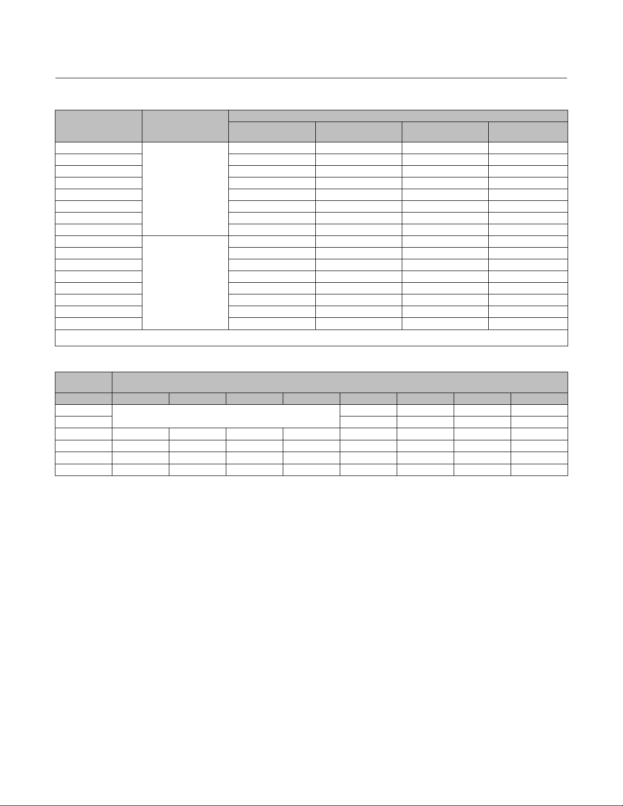
Table 2. Standard Constructions
ACTUATOR
SIZE
12 305 16 730 32or 51 127 or 178 >203 610
14 356 32 993 32or 51 127 or 178 >203 610
16 406 32 1297 32 or 51 127 or 178 >203 610
18 457 32 1642 32 or 51 127 or 178 >203 610
20 508 46 2027 32 or 51 127 or 178 25 610
22 559 46 2452 32 or 51 127 or 178 25 610
24 610 62 2919 32 or 51 127 or 178 25 610
26 660 62 3425 32 or 51 127 or 178 25 610
12 12 2.41 113 1-1/4 or 2 5H or 7 >8 24
14 14 4.91 154 1-1/4 or 2 5H or 7 >8 24
16 16 4.91 201 1-1/4 or 2 5H or 7 >8 24
18 18 4.91 254 1-1/4 or 2 5H or 7 >8 24
20 20 7.07 314 1-1/4 or 2 5H or 7 1 24
22 22 7.07 380 1-1/4 or 2 5H or 7 1 24
24 24 9.62 452 1-1/4 or 2 5H or 7 1 24
26 26 9.62 531 1-1/4 or 2 5H or 7 1 24
1. Consult your Emerson Process Management sales office for additional sizes.
PISTON
DIAMETER
(1)
PISTON ROD
AREA
PISTON AREA
mm (cm2for Area)
Inches (inch2for Area)
VALVE STEM
CONNECTOR SIZE
YOKE BOSS
DIAMETER
VALVE TRAVEL
Minimum Maximum
3
Page 4
685 Piston Actuator
September 2014
Instruction Manual
D103626X012
Table 3. Thrust
THRUST AT SUPPLY PRESSURE, N (LBF)
ACTUATOR SIZE STROKE
12
14 41083 (9236) 54777 (12315) 68472 (15394) 102707 (23091)
16 53659 (12064) 71546 (16085) 89432 (20106) 134149 (30159)
18 67913 (15268) 90550 (20358) 113188 (25447) 169782 (38170)
20 83843 (18850) 111790 (25133) 139738 (31416) 209607 (47124)
22 101450 (22808) 135266 (30411) 169083 (38013) 253625 (57020)
24 120734 (27143) 160978 (36191) 201223 (45239) 301834 (67858)
26 141694 (31856) 188926 (42474) 236157 (53093) 354236 (79639)
12
14 39773 (8942) 53030 (11922) 66288 (14903) 99432 (22354)
16 52349 (11769) 69799 (15692) 87248 (19615) 130873 (29423)
18 66602 (14974) 88803 (19965) 111004 (24956) 166506 (37434)
20 81956 (18425) 109275 (24567) 136593 (30709) 204890 (46063)
22 99563 (22384) 132751 (29845) 165938 (37306) 248907 (55959)
24 118166 (26566) 157555 (35422) 196944 (44277) 295416 (66415)
26 139127 (31279) 185503 (41705) 231878 (52131) 347817 (78196)
1. Consult your Emerson Process Management sales office for supply pressures below 40 psig.
2. Maximum available thrust.
Push
Pull
4.1 barg (60 psig) 5.5 barg (80 psig) 6.9 barg (100 psig)
30183 (6786) 40245 (9048) 50306 (11310) 75459 (16965)
29540 (6641) 39387 (8855) 49234 (11069) 73851 (16603)
(1)
10.3 barg
(150 psig)
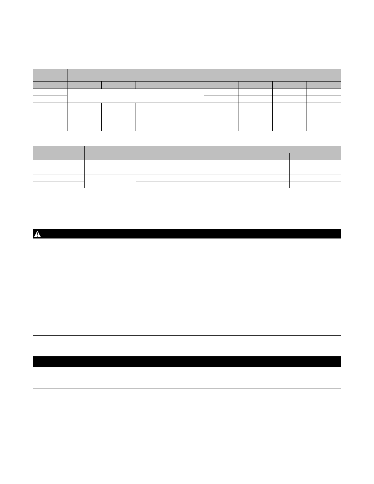
Table 4. Approximate Weights for Constructions without Handwheels
MAXIMUM
VALVE TRAVEL
mm (inches) 12 14 16 18 20 22 24 26
102 (4.00) 402 (886) 475 (1048) 662 (1459) 761 (1677)
203 (8.00) 430 (947) 505 (1114) 702 (1548) 804 (1771)
305 (12.00) 157 (346) 245 (541) 292 (643) 337 (742) 457 (1008) 535 (1180) 743 (1637) 847 (1866)
406 (16.00) 168 (370) 262 (577) 311 (686) 358 (789) 485 (1069) 565 (1246) 783 (1726) 889 (1961)
508 (20.00) 179 (395) 278 (614) 331 (729) 379 (836) 512 (1129) 595 (1311) 823 (1815) 932 (2056)
610 (24.00) 190 (420) 295 (650) 350 (773) 401 (883) 540 (1190) 625 (1377) 864 (1904) 975 (2150)
APPROXIMATE WEIGHT FOR ACTUATOR SIZE, kg (lbs)
(2)
4
Page 5
Instruction Manual
D103626X012
685 Piston Actuator
September 2014
Table 5. Approximate Weights for Constructions with Handwheels
MAXIMUM
VALVE TRAVEL
mm (inches) 12 14 16 18 20 22 24 26
102 (4.00) 591 (1304) 664 (1463) 834 (1838) 925 (2038)
203 (8.00) 622 (1372) 696 (1535) 873 (1924) 965 (2128)
305 (12.00) 226 (499) 363 (800) 292 (643) 454 (1000) 653 (1440) 729 (1607) 912 (2010) 1006 (2218)
406 (16.00) 239 (527) 380 (838) 311 (686) 474 (1046) 684 (1508) 762 (1679) 951 (2096) 1047 (2308)
508 (20.00) 252 (555) 397 (876) 331 (729) 495 (1092) 715 (1576) 794 (1751) 990 (2182) 1088 (2398)
610 (24.00) 264 (583) 415 (914) 350 (773) 516 (1138) 746 (1644) 827 (1823) 1029 (2268) 1129 (2488)
APPROXIMATE WEIGHT FOR ACTUATOR SIZE, kg (lbs)
Table 6. Lifting Point Load Ratings
ACTUATOR SIZE
12 to 24
26 2 2860 6300
12 to 24
26 2 6350 14000
LIFTING
ORIENTATION
Actuator Centerline
Horizontal
Actuator Centerline
Vertical
NUMBER OF LIFTING POINTS USED
2 1540 3400
2 3760 8300
MAXIMUM LOAD
kg lbs
Installation
WARNING
Always wear protective gloves, clothing, and eyewear when performing any installation operations to avoid personal
injury.
To avoid personal injury or property damage caused by bursting of pressure-retaining parts, be certain the cylinder
pressure or other pressure ratings do not exceed the limits listed in table 1. Use pressure-limiting or pressure-relieving
devices to prevent cylinder pressure or other pressures from exceeding these limits.
Check with your process or safety engineer for any additional measures that must be taken to protect against process
media.
If installing into an existing application, also refer to the WARNING at the beginning of the Maintenance section in this
instruction manual.
Dropping the actuator and any attached accessories and/or valve may cause personal injury and/or equipment damage. For
all mounting procedures use an adequately sized chain, sling, hoist, or crane to handle the actuator and any attached
accessories and/or valve. Use caution during lifting and handling to prevent slippage, swinging, faulty equipment
connections, or sudden shock loads.
CAUTION
Special care must be taken when installing an actuator in a horizontal service orientation. To avoid cantilever loads on the
valve stem and yoke, it is the customer’s responsibility to ensure proper support for a horizontal actuator.
When an actuator and control valve are shipped together as a control valve assembly, the actuator is normally
mounted on the valve. Follow the valve instructions when installing the valve in the pipeline. If the actuator is shipped
separately or if it is necessary to mount the actuator on the valve, perform the actuator mounting procedures in this
instruction manual. Refer to the individual product instruction manuals for the installation or mounting of a FIELDVUE
DVC6200 digital valve controller or 3610 positioner.
5
Page 6

685 Piston Actuator
September 2014
If the actuator is being installed without a positioner, the cylinder loading pressures should be supplied through a
4way solenoid valve or a switching valve. The top and bottom sides of the piston are pressurized through the upper
and lower heads (i.e. top and bottom of the cylinder).
The supply pressure medium should be clean, dry filtered air. If the supply source is capable of exceeding the
maximum actuator operating pressure or positioner supply pressure, appropriate steps must be taken during
installation to protect the positioner and all connected equipment against over pressurization.
The control valve should be located where it will be accessible for servicing. Room should be left above and below the
control valve to permit removal of the actuator and valve plug.
Instruction Manual
D103626X012
ThreeWay Valve Applications Note
In threeway valve applications where the actuator fully strokes at a frequency of once per minute or faster, and the
stroking speed is rapid (less than 0.5 seconds per stroke), there is a possibility that the stem can fracture at the plug if
the actuator cylinder pressure is greater than 5.5 bar (80 psig). This can cause loss of control of process fluid and
further damage to the actuator. Consideration should be given to the use of highstrength, fatigueresistant stem
materials in these applications.
Actuator Mounting
The following procedure describes how to mount a 685 actuator on a pushdowntoclose valve so that the piston rod
to valve plug stem connection allows full travel and proper shutoff. Key numbers referenced in the following steps are
showninfigures2and3.
If you purchase a 685 actuator for field installation on a control valve, mount the actuator on the valve and secure it to
the bonnet with the eight bonnet-to-actuator bolts. The stem connection should then be made up to clamp the
actuator stem and valve plug stem together to provide proper valve travel.
CAUTION
If the valve stem is allowed to remain in the up position (towards the actuator) during mounting, it can interfere with the
actuator mounting, possibly damage valve stem threads, or bend the valve stem. Be sure the valve stem is pushed down
(into the valve body), away from the actuator while mounting.
To avoid damaging the seating surfaces, do not rotate the valve plug while it is seated. Also avoid damage to the valve plug
stem by careful use of tools during travel adjustment.
1. Thread two lifting eyes into the free ports on the upper head (key 1) 180 degrees apart. Reference tables 4 and 5 for
approximate weights of the actuator to select an appropriate lifting eye. Attach appropriate rigging gear to the
lifting eyes.
2. Slowly lower the actuator down onto the valve. Once the actuator is in place, insert the bonnettoactuator bolts
and tighten the hex nuts.
3. Turn the two stem locknuts (if present) all the way onto the valve stem thread.
4. Starting with the cylinder fully retracted, manually, or with air pressure, extend the piston rod to the specified valve
travel.
5. Attach the stem connector (key 18), clamping the piston rod (key 17) to the valve stem. Be sure you also attach the
feedback arm and travel indicator.
6. Cycle the actuator to check availability of desired total travel and that the valve plug seats before the cylinder
reaches the end of its stroke. You can make minor travel adjustments, if necessary, by loosening the stem
6
Page 7

Instruction Manual
D103626X012
685 Piston Actuator
September 2014
connector slightly, tightening the locknuts together, and (with the valve plug off the seat) screwing the stem either
into or out of the stem connector by means of a wrench on the locknuts.
7. If the total travel is adequate, tighten the stem connector (key 18) securely, lock the stem loc knuts (if present)
against the connector, and adjust the indicator scale (key 22) on the yoke (key 21) to show valve plug position.
8. Provide a gauge, if necessary, to measure the pressure to the actuator. Make a final adjustment on the positioner to
set the starting point of valve travel and to obtain full travel for the given instrument range.
Handwheel Operation
If manual operation is required, the actuator should be equipped with a manual handwheel.
CAUTION
To avoid damage to actuator parts and difficult operation of actuator handwheels, open the bypass valve (key 66) before
using a handwheel.
The bypass assembly is furnished only when a handwheel actuator is specified. The bypass allows the pressure to
equalize on either side of the piston, so that the manual actuator can be used to position the control valve. Flow
through the bypass tubing is controlled by an angle needle valve, which is operated manually. This valve should be
closed when air pressure is being used to operate the actuator.
Key numbers referenced in the following steps are shown in figure 2. Refer to table 7 for handwheel specifications.
1. Open the bypass valve.
2. Rotatethehandwheel(key45)topositiontheoverrideengagepin(key38)withtheholeinthestemconnector
(key 10). Turn the engage pin control knob (key 33) clockwise to insert the override engage pin into the stem
connector until it stops.
Note
Depending on construction , the handwheel may have operation information stamped into the part. Always refer to steps 3 and 4
for operation information specific to push-down-to-close and push-down-to-open valves.
3. For a pushdowntoclose valve: Rotate the handwheel (key 45) clockwise to close the valve and counterclockwise
to open the valve.
4. For a pushdowntoopen valve: Rotate the handwheel (key 45) counterclockwise to close the valve and clockwise
to open the valve.
5. To disengage the manual handwheel, rotate the handwheel (key 45) to relieve any load placed on the override
engage pin (key 38), turn the engage pin control knob (key 33) counter-clockwise until it stops.
Table 7. Handwheel Specifications
ACTUATOR SIZE
12 44482 10000 305 12 3.8 96 290 65
14 to 18 88964 20000 406 16 3.0 80 380 85
20 to 26 133447 30000 610 24 2.8 72 450 100
OUTPUT THRUST HANDWHEEL DIAMETER
N lbs mm Inch N lbs
TURNS PER mm
OF TRAVEL
TURNS PER
INCH OF
TRAVEL
MAXIMUM RIM FORCE
REQUIRED
7
Page 8

685 Piston Actuator
September 2014
Instruction Manual
D103626X012
Maintenance
WARNING
Avoid personal injury from sudden release of process pressure. Before performing any maintenanceoperations:
D Do not remove the actuator from the valve while the valve is still pressurized.
D Always wear protective gloves, clothing, and eyewear when performing any maintenance operations to avoid personal
injury.
D Disconnect any operating lines providing air pressure, electric power, or a control signal to the actuator. Be sure the
actuator cannot suddenly open or close the valve.
D Use bypass valves or completely shut off the process to isolate the valve from process pressure. Relieve process pressure
on both sides of the valve. Drain the process media from both sides of the valve.
D Use lock-out procedures to be sure that the above measures stay in effect while you work on the equipment.
D The valve packing box may contain process fluids that are pressurized, even when the valve has been removed from the
pipeline. Process fluids may spray out under pressure when removing the packing hardware or packing rings, or when
loosening the packing box pipe plug.
D Check with your process or safety engineer for any additional measures that must be taken to protect against process
media.
Instructions are given below for complete disassembly of the actuator, seal replacement, and Oring replacement.
When inspection or repair is necessary, disassemble the actuator only as far as is required to accomplish the job. Key
numbers referenced in the following steps are shown in figures 2 and 3.
Actuator Removal
Thefollowingprocedureisfortheremovaloftheactuatorfromavalve.
1. Disconnect the actuator tubing from the pressure connections on the upper and lower heads (keys 1 and 9) and
positioner.
Note
Refer to the appropriate instruction manual for any maintenance or adjustments that need to be made on the positioner.
2. Break the stem connection by removing hex nuts (key 57),lockwashers(key10),andstuds(key58)fromthestem
connector (key 18).
3. Remove the bonnet-to-actuator bolting securing the actuator to the valve bonnet.
4. Thread two lifting eyes into the free ports on the upper head (key 1) 180 degrees apart. Reference tables 4 and 5 for
approximate weights of the actuator to select an appropriate lifting eye. Attach appropriate rigging gear to both
lifting eyes and lift the actuator away from the valve bonnet and stem.
5. Place the actuator upside-down with the upper head (key 1) flat against the ground. Cloth or wood should be used
to prevent against paint damage.
6. Refer to the Actuator Mounting section of this manual for instructions on mounting and installing the actuator onto
avalve
8
Page 9

Instruction Manual
D103626X012
685 Piston Actuator
September 2014
Seal and Oring Replacement
The following procedure is for the replacement of the internal piston seals, bearing seals, and Orings.
1. Complete Actuator Removal procedures above.
If the actuator has a handwheel manual override proceed to step 2, otherwise proceed directly to step 8.
2. Reposition the actuator so it is rightside up with the yoke (key 21) flat against the ground. Cloth or wood should
be used to prevent against paint damage.
3. Measure the gap between the piston rod (key 17) and the engage/disengage block (key 43) — up to 1/8 inch — and
make note, as this will be used during reassembly.
4. Removethesetscrew(key36)fromtheengage/disengageblock(key43).
5. Remove the hex head cap screws (key 20) and lock washers (key 10) that secure the yoke (key 21) to the lower head
(key 9).
6. Using the same lifting eyes as in the Actuator Removal section, attach appropriate rigging gear and remove the
cylinderassemblyfromtheyoke(key21).Therigginggearshould allow the cylinder to be rotated freely. Rotate the
cylinder assembly to unscrew the engage/disengage block (key 43) from the piston rod (key 17). After the
engage/disengage block is removed, secure the cylinder assembly to the yoke using the hex head cap screws (key
20) and lock washers (key 10).
7. Place the actuator upsidedown with the upper head (key 1) flat against the ground. Cloth or wood should be used
to prevent against paint damage.
8. Loosen tie bolt hex nuts (key 11) in a crisscross pattern. Remove tie rod hex nuts and lock washers (key 10).
9. Remove the yoke (key 21) and the lower head (key 9) assembly from the cylinder (key 4) and place onto a flat
surface with the Oring side facing up. Using straps, secure this assembly to a solid structure to prevent it from
falling over.
10. Extract bearing assembly (keys 12, 13, 14, and 15) from lower head (key 9) by removing the bearing retaining ring
(key 16).
11. Remove the piston wiper seal (key 15), Oring (key 13), and quad seal (key 12) from the bearing (key 14).
12. Clean bearing (key 14) with a light degreaser, if needed.
13. Lightly grease the new Oring (key 13) and quad seal (key 12), then install onto bearing (key 14). Without grease,
install a new piston wiper seal (key 15) onto the bearing.
14. Reinstall bearing assembly (keys 12, 13, 14, and 15) into lower head (key 9) and secure in place with the bearing
retaining ring (key 16).
15. Remove the Oring (key 2) from the lower head (key 9) and clean the groove with a light degreaser.
16. Lightly grease the new Oring (key 2) and install on lower head (key 9).
17. Remove tie bolts (key 3) from upper head (key 1).
18. Lift piston assembly (keys 5, 6, 7, 17, and 19) out from cylinder (key 4) and place on a flat surface.
19. Remove the wear ring (key 6) and quad seal (key 7) from the piston (key 5).
20. Thread locking compound is applied to the threads of the piston rod (key 17) by the manufacturer during initial
assembly. As a result, disassembly will require heating to loosen the thread locking compound. To remove the
piston rod Oring (key 19), heat the piston assembly using a torch and unthread the piston rod (key 17) from the
piston (key 5).
21. After the piston rod (key 17) has completely cooled, remove the piston rod Oring (key 19). Clean the piston rod
Oring groove with a light degreaser. Lightly grease a new piston rod Oring and install onto the piston rod.
22. Reinstall piston rod (key 17) onto piston (key 5) using thread locking compound.
23. Clean piston seal grooves. Install new lightly greased quad seal (key 7) onto piston (key 5).
9
Page 10

685 Piston Actuator
September 2014
Instruction Manual
D103626X012
24. Without grease, trim to length and then install a new wear ring (key 6).
25. Lift cylinder (key 4) vertically and place on a flat surface. Take extra precaution to avoid scratching or gouging the
inner diameter of the cylinder.
26. Remove Oring (key 2) from the upper head (key 1) and clean the seal groove. Install lightly greased new Oring
into upper head seal groove.
27. Install cylinder (key 4) onto upper head (key 1) making sure the Oring (key 2) does not move out of its groove.
28. Carefully install the piston assembly (keys 5, 6, 7, 17, and 19) into cylinder (key 4) making sure all seals and Orings
stay in place on the outside diameter of the piston (key 5).
29. Install tie bolts (key 3) into upper head (key 1).
30. Carefully install the yoke (key 21) and the lower head (key 9) assembly onto cylinder (key 4) taking care not to
damage threads on the tie bolts (key 3). Be sure the Oring (key 2) is in place during this step.
31. Install lock washers (key 10) and tie rod hex nuts (key 11) onto tie bolts (key 4). Torque in a crisscross pattern
according to table 2.
If the actuator has a handwheel manual override proceed to step 32, otherwise proceed directly to step 37.
32. Reposition the actuator so it is rightside up with the yoke (key 21) flat against the ground. Cloth or wood should
be used to prevent against paint damage.
33. Remove the hex head cap screws (key 20) and lock washers (key 10) that secure the yoke (key 21) to the lower
head (key 9).
34. Using the same lifting eyes as in the Actuator Removal section attach appropriate rigging gear and remove the
cylinderassemblyfromtheyoke(key21).Therigginggearshould allow the cylinder to be rotated freely. Rotate the
cylinder assembly to screw the engage/disengage block (key 43) onto the piston rod (key 17) until the gap
measured in step 3 is achieved.
35. Tighten the set screw (key 36) into the engage/disengage block (key 43).
36. Securethecylinderassemblytotheyokeusingthehex head cap screws (key 20) and lock washers (key 10).
Torque in a crisscross pattern according to table 8.
37. Refer to the Actuator Mounting section of this manual for instructions on mounting and installing the actuator
onto a valve.
Table 8. Tie Bolt Torque
BOLT DIAMETER
1/4-20 8 6
5/16-18 15 11
3/8-16 26 19
7/16-14 39 29
1/2-13 60 44
9/16-12 84 62
5/8-11 115 85
3/4-10 198 146
7/8-9 313 231
1-8 445 328
1-1/8-7 662 488
10
TORQUE
N•m lbf•ft
Page 11

Instruction Manual
D103626X012
685 Piston Actuator
September 2014
Parts Ordering
When corresponding with your Emerson Process Management sales office about this equipment, refer to the serial
numbers (there are two serial n umbers located on the actuator) found on the actuator nameplate (key 22). Also,
specify the complete 11-character part number from the following Parts List when ordering replacement parts.
WARNING
Use only genuine Fisher replacement parts. Components that are not supplied by Emerson Process Management should
not, under any circumstances, be used in any Fisher valve, because they may void your warranty, might adversely affect the
performance of the valve, and could cause personal injury and property damage.
Parts Kits
Includes all soft seals and O-rings required for seal and O-ring replacement in standard operating temperature
constructions. Refer to figures 2 and 3.
PART NUMBER
KIT CONTENTS ACTUATOR SIZE
Piston Rod Wiper Seal, key 15
Bearing Oring, Key 13
Bearing Quad Seal, Key 12
Piston Rod Oring, Key 19
Piston Wear Ring, Key 6
Piston Quad Seal, Key 7
Upper/Lower Head Oring, Key 2
Upper/Lower Head Oring, Key 2
12 R685X000012
14 R685X000022
16 R685X000032
18 R685X000042
20 R685X000052
22 R685X000062
24 R685X000072
26 R685X000082
Standard
Temperature
Low
Temperature
R685X000092 R685X000172
R685X000102 R685X000182
R685X000112 R685X000192
R685X000122 R685X000202
R685X000132 R685X000212
R685X000142 R685X000222
R685X000152 R685X000232
R685X000162 R685X000242
High
Temperature
11
Page 12

685 Piston Actuator
September 2014
Instruction Manual
D103626X012
Parts List
Note
For part numbers not shown, contact your Emerson Process
Management sales office.
Common Parts (figures 2 and 3)
Key Description
1 Upper Head
2 Upper/Lower HeadO-ring
3 Tie Bolt
4Cylinder
5Piston
6 Piston Wear Ring
7PistonQuadSeal
9LowerHead
10 Lock Washer
11 Tie Bolt Hex Nut
12 Bearing Quad Seal
13 Bearing O-ring
14 Bearing
15 Piston Rod Wiper Seal
16 Bearing Retaining Ring
17 Piston Rod
18 Stem Connector
19 Piston Rod O-ring
20 Hex Head Cap Screw
21 Yoke
22 Travel Scale
57 Stem Connector Hex Nut
58 Stem Connector Stud
100 Multi-purpose Grease, MPG-2 or approved equivalent
Manual Handwheel Parts
(figure 2)
Key Description
24 ACME Thrust Shaft
25 Override Guide Shaft
26 Worm Gear
27 Thrust Shaft Upper Bushing
28 Thrust Shaft Bushing
29 Thrust Bearing
30 Thrust Guide Block
31 Engage Pin Guide
32 Guide Block Engage Screw
33 Engage Pin Control Knob
34 Engage Spring Pin
35 Socket Head Cap Screw
36 Socket Set Screw
37 Key
38 Override Engage Pin
39 Position Indicator
40 All Thread Stud
41 Flat Washer
42 Yoke Adaption Bracket
43 Engage/DisengageBlock
44 Stem Connector Stud
45 Handwheel
46 Helix Housing Cap O-ring
47 Helix Gear Shaft Bushing
48 Helix Gear Bushing
49 Helix Worm Gear Housing
50 Helix Worm Gear
51 Helix Gear Shaft Spacer
52 Helix Shaft Wiper Seal
53 Helix Worm Gear Shaft
54 Helix Gear Housing Cap
55 Ext. Tooth Lock Washer
56 Pointer
12
Page 13

Instruction Manual
D103626X012
Figure 2. Fisher 685 with Manual Handwheel
100
100
685 Piston Actuator
September 2014
100
100
100
100
E1565
LEFT SIDE VIEW
FRONT VIEW
RIGHT SIDE VIEW
13
Page 14

685 Piston Actuator
September 2014
Figure 3. Fisher 685 without Manual Handwheel
100
100
2
100
100
100
Instruction Manual
D103626X012
E1566
57
58
14
Page 15

Instruction Manual
D103626X012
685 Piston Actuator
September 2014
15
Page 16

685 Piston Actuator
September 2014
Instruction Manual
D103626X012
Neither Emerson, Emerson Process Management, nor any of their affiliated entities assumes responsibility for the selection, use or maintenance
of any product. Responsibility for proper selection,use, and maintenance of any product remains solely with the purchaser and end user.
Fisher, easy-e, and FIELDVUE are marks owned by one of the companies in the Emerson Process Management business unit of EmersonElectric Co.Emerson
Process Management, Emerson, and the Emerson logo are trademarks and service marks of Emerson Electric Co. All other marks are the property of their
respective owners.
The contents of this publication are presented for informational purposes only, and while every effort has been made to ensure their accuracy, they arenot
to be construed as warranties or guarantees, express or implied, regarding the products or services described herein or their use or applicability. All sales are
governed by our terms and conditions,which are available upon request. We reserve the right to modify or improve the designs or specifications ofsuch
products at any time without notice.
Emerson Process Management
Marshalltown, Iowa 50158 USA
Sorocaba, 18087 Brazil
Chatham, Kent ME4 4QZ UK
Dubai, United Arab Emirates
Singapore 128461 Singapore
www.Fisher.com
16
E 2013, 2014 Fisher Controls International LLC. All rights reserved.
 Loading...