


PV101
PV100 SERIES
ELECTRONICALLY CONTROLLED
PROPORTIONAL VALVES
INSTRUCTION
SHEET
M2160-0204
Unpacking
Remove the Packing List and verify that you have
received all equipment, including a PV100 Series
proportional valve, and instruction sheet. If you
have any questions about the shipment, please call
the Customer Service Department at 1-800-622-2378
or 203-359-1660. We can also be reached on the
Internet at www.omega.com
e-mail: cservice@omega.com
When you receive the shipment, inspect the
container and equipment for signs of damage. Note
any evidence of rough handling in transit.
Immediately report any damage to the shipping
agent.
General Description
The OMEGA
®
PV100 Series Electronically
Controlled Proportional Valves are two-way
normally closed valves. When the valve is
deenergized, pressure is sealed off by the force of
the plunger assembly return spring and the seal in
the plunger assembly. When the valve is energized,
the plunger assembly moves upward, permitting
flow through the valve. The valve is direct acting.
Higher current or control signal results in more
plunger movement and more flow.
Installation
Port Identification
Apply inlet pressure to the port marked “P”.
Mounting Position and Pressure Limits
Valves can be mounted directly on piping and are
designed to operate in any position. Two 8-32
tapped mounting holes
1
⁄4” deep are provided in the
base of the body. Line pressure must not exceed the
nameplate rating.
Piping
Remove closures from ports and connect pressure
lines to proper ports. All valves have
1
⁄8" NPTF
fittings. Tightening torque on the
1
⁄8" NPT should
not exceed 38 in-lbs.
Media Filtration
Filtration of air lines is recommended. Install the
filter in the inlet side as close to the valve as
possible. These valves have no sliding fits and are
generally not sensitive to a small amount of foreign
material, however, they do contain soft rubber
inserts. Dirt or foreign material in the media may
cause excessive leakage, excessive wear, or in
exceptional cases, malfunction.
Electrical Connection
Electrical supply must conform to nameplate
rating. Connect coil leads to DC voltage using
standard electrical practice.
Black wire Common Ground
(to Power Supply and Control)
Red wire (+) DC Positive Power Supply
Gray wire (+) Control Signal
If the coil housing is located in an inconvenient
position, the housing nut can be loosened and the
housing rotated to any convenient position. Then
re-tighten the nut to 13 to 35 in-lbs.
Coil Housing Temperature
Standard valves are supplied with coils designed
for continuous duty service. Normal free space
must be provided for proper ventilation. When coil
is energized continuously for long periods of time,
the coil housing will become hot 54 to 71°C (130 to
160°F). The coil is designed to operate continuously
under these conditions. Any excessive heating will
be indicated by smoking and/or odor of burning
insulation.
Lubrication
Lubrication is not required.
Maintenance Instructions
Valves are calibrated at the factory and should not
be disassembled by the user.
Available Models
*Specify Control Signal: MA for 4-20 MADC
5V for 0-5 VDC
10V for 0-10 VDC
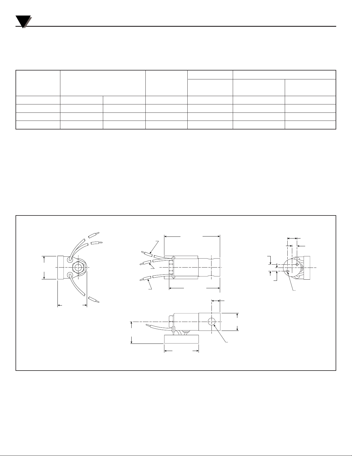
Dimensions
PV100 Series Proportional Valves
Flow Ranges, SCCM
Model Orifice Maximum At Maximum At
Number Millimeters Inches
C
v Pressure Pressure 10 PSI
PV101-(*) .80 1/32 0.02 200 PSI 0-50,000 0-8,000
PV102-(*) 1.19 3/64 0.045 100 PSI 0-65,000 0-17,000
PV103-(*) 1.59 1/16 0.08 60 PSI 0-75,000 0-30,000
PV104-(*) 1.98 5/64 0.12 40 PSI 0-80,000 0-45,000
35.05 ±0.38
(1.38 ±0.015)
45.47 ±0.51
(1.79 ±0.02)
84.07 ±1.0
(3.31 ±0.04)
10.1
(0.396)
5.0
(0.198)
RED
POSITIVE
BLACK
COMMON
GRAY
CONTROL
ELECTRICAL TERMINATIONS
RED - DC POWER SUPPLY (+)
GRAY - CONTROL SIGNAL (+)
BLACK - COMMON (TO POWER
SUPPLY AND CONTROL SIGNAL)
74.45 ±0.51
(3.01 ±0.02)
50.80 ±0.51
(2.00 ±0.02)
15.0
(0.59)
7.5
(0.295)
13.46
(0.53)
P
32.51
(1.28)
26.92 DIA.
(1.06 DIA.)
1/8 NPT
2 PLC'S
#8-32 NC-2B TH'D
2 PLC'S
DIMENSIONS mm (inches)
2
 Loading...