

Page 1
Bedienungsanleitung
Doppelschleifer
Operating Instructions
Double-Wheel Grinder/Sander
Mode d’emploi
de la meuleuse double
4 Uputstva za upotrebu
Dvostruka brusilica
Istruzioni per l’uso
Levigatrice doppia
Betjeningsvejledning
dobbeltsliber
j Návod k obsluze
Dvojitá bruska
Használati utasítás
Kettős köszörűgép
B
Upute za uporabu
f dvostruke brusilice
W Návod na obsluhu
Dvojitá brúska
BT-BG 175
Art.-Nr.: 44.126.04 I.-Nr.: 01017
Anleitung_BT_BG_175_SPK1:_ 28.08.2007 16:07 Uhr Seite 1
Page 2
2
1
2 3
14
8
3
5
14
3
14 13 12 7 6
4
2
5
7
4
7
2
3
11
10
9
1
Anleitung_BT_BG_175_SPK1:_ 28.08.2007 16:07 Uhr Seite 2
Page 3
3
7
4
6
5
4
14
15
13
12
7
6
A
A
B
A
10
3
11
3
8
C
5
D
Anleitung_BT_BG_175_SPK1:_ 28.08.2007 16:07 Uhr Seite 3
Page 4
4
D
Achtung!
Beim Benutzen von Geräten müssen einige
Sicherheitsvorkehrungen eingehalten werden, um
Verletzungen und Schäden zu verhindern. Lesen Sie
diese Bedienungsanleitung deshalb sorgfältig durch.
Bewahren Sie diese gut auf, damit Ihnen die
Informationen jederzeit zur Verfügung stehen. Falls
Sie das Gerät an andere Personen übergeben
sollten, händigen Sie diese Bedienungsanleitung
bitte mit aus.
Wir übernehmen keine Haftung für Unfälle oder
Schäden, die durch Nichtbeachten dieser Anleitung
und den Sicherheitshinweisen entstehen.
1. Sicherheitshinweise
Die entsprechenden Sicherheitshinweise finden Sie
im beiliegenden Heftchen!
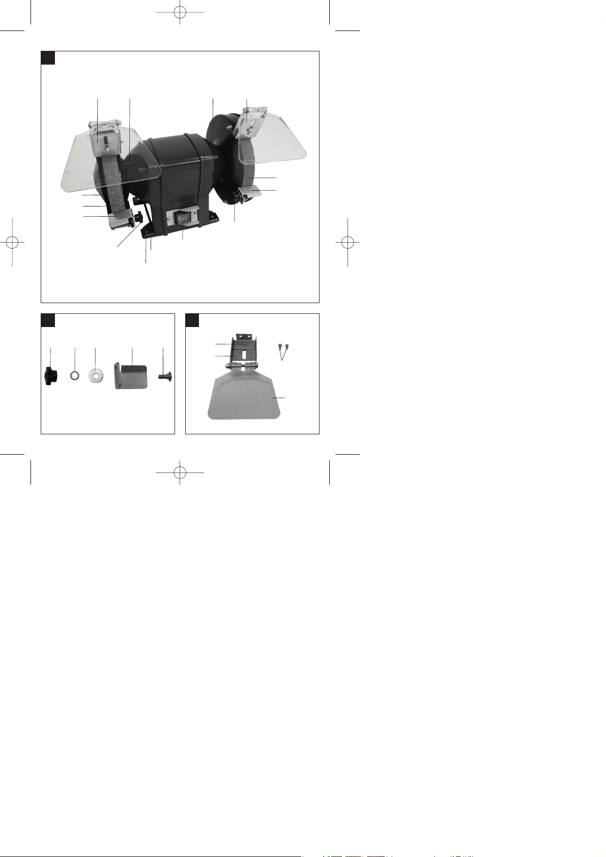
2. Gerätebeschreibung (Bild 1)
1 Ein-Aus-Schalter
2 Schutzglas
3 Funkenabweiser
4 Schutzhaube
5 Schleifscheibe
6 Befestigungsschraube Werkstückauflage
7 Werkstückauflage
8 Befestigungslöcher
9 Standfuß
10 Befestigungsschrauben Funkenabweiser
11 Justierschraube Funkenabweiser
12 Unterlegscheibe
13 Zahnscheibe
14 Feststellknopf Werkstückauflage
15 Halterung Werkstückauflage
3. Bestimmungsgemäße Verwendung
Der Doppelschleifer ist ein Kombigerät für Grob- und
Feinschliff von Metallen, Kunstoffen und anderen
Materialien unter Verwendung der entsprechenden
Schleifscheiben.
Die Maschine darf nur nach ihrer Bestimmung
verwendet werden! Trotz bestimmungsgemäßer
Verwendung können bestimmte Restrisikofaktoren
nicht vollständig ausgeräumt werden. Bedingt durch
die Konstruktion und den Aufbau der Maschine
können folgende Punkte auftreten:
쎲 Berührung der Schleifscheibe im nicht
abgedeckten Bereich.
쎲 Herausschleudern von Teilen aus beschädigten
Schleifscheiben.
쎲 Herausschleudern von Werkstücken und
Werkstückteilen.
쎲 Gehörschäden bei Nichtverwendung des nötigen
Gehörschutzes.
Die Maschine darf nur nach ihrer Bestimmung
verwendet werden. Jede weitere darüber
hinausgehende Verwendung ist nicht
bestimmungsgemäß. Für daraus hervorgerufene
Schäden oder Verletzungen aller Art haftet der
Benutzer/Bediener und nicht der Hersteller.
Bitte beachten Sie, dass unsere Geräte
bestimmungsgemäß nicht für den gewerblichen,
handwerklichen oder industriellen Einsatz konstruiert
wurden. Wir übernehmen keine Gewährleistung,
wenn das Gerät in Gewerbe-, Handwerks- oder
Industriebetrieben sowie bei gleichzusetzenden
Tätigkeiten eingesetzt wird.
4. Technische Daten
Nennspannung: 230 V ~ 50 Hz
Aufnahmeleistung: 400 W S2 30 min
Leerlaufdrehzahl n0: 2800 min
-1
ø Schleifscheibe: 175 mm
Schleifscheibendicke: 25 mm
ø Bohrung Schleifscheibe: 32 mm
max. Umfanggeschwindigkeit: 25,64 m/s
Gewicht 10,2 kg
Anleitung_BT_BG_175_SPK1:_ 28.08.2007 16:07 Uhr Seite 4
Page 5
5
D
Einschaltdauer:
Die Einschaltdauer S2 30 min (Kurzzeitbetrieb) sagt
aus, dass der Motor mit der Nennleistung (400 W)
nur für die auf dem Datenschild angegebene Zeit (30
min) dauernd belastet werden darf. Andernfalls
würde er sich unzulässig erwärmen. Während der
Pause kühlt sich der Motor wieder auf seine
Ausgangstemperatur ab.
Geräuschemissionswerte
Das Geräusch dieser Maschine wird nach DIN EN
ISO 3744; EN ISO 11201 gemessen. Das Geräusch
am Arbeitsplatz kann 85 dB (A) überschreiten. In
diesem Fall sind Schallschutzmaßnahmen für den
Benutzer erforderlich. (Gehörschutz tragen!)
Leerlauf
Schalldruckpegel LpA: 81,5 dB
Schalleistungspegel LWA: 94,5 dB
5. Vor Inbetriebnahme
Ziehen Sie vor allen Wartungs- und
Montagearbeiten den Netzstecker.
쎲 Die Maschine muss standsicher aufgestellt
werden, d. h. auf einer Werkbank o. ä.
festschrauben.
쎲 Vor Inbetriebnahme müssen alle Abdeckungen
und Sicherheitsvorrichtungen ordnungsgemäß
montiert sein.
쎲 Die Schleifscheiben müssen frei laufen können.
쎲 Überzeugen Sie sich vor dem Anschließen der
Maschine, dass die Daten auf dem Typenschild
mit den Netzdaten übereinstimmen.
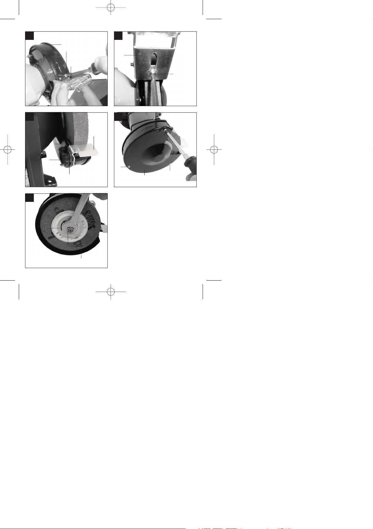
5.1 Montage Funkenabweiser (Bild 1/3/4/5)
쎲 Führen Sie den Funkenabweiser (3) unter die
Schutzhaube (4). Schrauben Sie den
Funkenabweiser (3) von oben mit den
Schrauben (10) an der Schutzhaube (4) fest
(Bild 4).
쎲 Stellen Sie den Funkenabweiser (3) mittels der
Justierschraube (11) so ein, dass der Abstand
zwischen Trockenschleifscheibe (5) und
Funkenabweiser (3) so gering wie möglich und in
keinem Fall größer als 2 mm ist.
쎲 Stellen Sie den Funkenabweiser (3) periodisch
so ein, so dass der Verschleiß der Scheibe
ausgeglichen wird.
5.2 Montage Werkstückauflage (Bild 2/6)
Montieren Sie die Werkstückauflage (7) mittels der
Befestigungsschraube Werkstückauflage (6),
Unterlegscheibe (12), Zahnscheibe (13) und
Feststellknopf Werkstückauflage (14) an der
Halterung Werkstückauflage (15), wie in Bild 6
gezeigt.
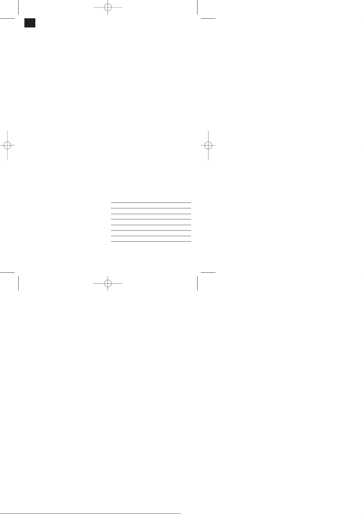
5.3 Wechsel der Schleifscheibe (Bild 7-8)
Entfernen Sie die 3 Schrauben (A) des
Schutzhaubenseitenteils (B) und nehmen Sie dieses
ab. Lockern Sie die Mutter (D) (Achtung die linke
Schleifscheibe ist mit einem Linksgewinde
verschraubt, die rechte Schleifscheibe mit einem
Rechtsgewinde), indem Sie die Mutter der
gegenüberliegenden Schleifscheibenhalterung
gegenhalten. Nehmen Sie anschließend den Flansch
(C) ab. Nun können Sie die Schleifscheibe (5)
austauschen. Die Montage erfolgt in umgekehrter
Reihenfolge.
6. Bedienung
6.1 Ein-/Ausschalter (1)
Stellen Sie den Ein-/Ausschalter (1) zum Einschalten
auf die Position 1.
Zum Ausschalten Ein-/Ausschalter (1) in Position 0
bringen.
Warten Sie nach dem Einschalten ab, bis das Gerät
seine maximale Drehzahl erreicht hat. Beginnen Sie
erst dann mit dem Schleifen.
6.2 Schleifen
쎲 Für feine Schleifarbeiten empfiehlt es sich die
feinkörnige Schleifscheibe zu benutzen, für
grobe Schleifarbeiten die grobkörnige
Schleifscheibe.
쎲 Legen Sie das Werkstück auf die
Werkstückauflage (7) auf und führen Sie es
langsam im gewünschten Winkel an die
Schleifscheibe (5) heran, bis es diese berührt.
쎲 Bewegen Sie das Werkstück leicht hin und her
um ein optimales Schleifergebnis zu erhalten.
Die Schleifscheibe (5) wird so außerdem
gleichmäßig abgenutzt. Lassen Sie das
Werkstück zwischendurch abkühlen.
Anleitung_BT_BG_175_SPK1:_ 28.08.2007 16:07 Uhr Seite 5
Page 6

6
D
7. Reinigung, Wartung und
Ersatzteilbestellung
Ziehen Sie vor allen Reinigungsarbeiten den
Netzstecker.
7.1 Reinigung
쎲 Halten Sie Schutzvorrichtungen, Luftschlitze und
Motorengehäuse so staub- und schmutzfrei wie
möglich. Reiben Sie das Gerät mit einem
sauberen Tuch ab oder blasen Sie es mit
Druckluft bei niedrigem Druck aus.
쎲 Wir empfehlen, dass Sie das Gerät direkt nach
jeder Benutzung reinigen.
쎲 Reinigen Sie das Gerät regelmäßig mit einem
feuchten Tuch und etwas Schmierseife.
Verwenden Sie keine Reinigungs- oder
Lösungsmittel; diese könnten die Kunststoffteile
des Gerätes angreifen. Achten Sie darauf, dass
kein Wasser in das Geräteinnere gelangen kann.
7.2 Wartung
Im Geräteinneren befinden sich keine weiteren zu
wartenden Teile.
7.3 Ersatzteilbestellung:
Bei der Ersatzteilbestellung sollten folgende
Angaben gemacht werden;
쎲 Typ des Gerätes
쎲 Artikelnummer des Gerätes
쎲 Ident-Nummer des Gerätes
쎲 Ersatzteilnummer des erforderlichen Ersatzteils
Aktuelle Preise und Infos finden Sie unter
www.isc-gmbh.info
8. Entsorgung und Wiederverwertung
Das Gerät befindet sich in einer Verpackung um
Transportschäden zu verhindern. Diese Verpackung
ist Rohstoff und ist somit wieder verwendbar oder
kann dem Rohstoffkreislauf zurückgeführt werden.
Das Gerät und dessen Zubehör bestehen aus
verschiedenen Materialien, wie z.B. Metall und
Kunststoffe. Führen Sie defekte Bauteile der
Sondermüllentsorgung zu. Fragen Sie im
Fachgeschäft oder in der Gemeindeverwaltung nach!
Anleitung_BT_BG_175_SPK1:_ 28.08.2007 16:07 Uhr Seite 6
Page 7
Important!
When using equipment, a few safety precautions
must be observed to avoid injuries and damage.
Please read the complete operating manual with due
care. Keep this manual in a safe place, so that the
information is available at all times. If you give the
equipment to any other person, give them these
operating instructions as well.
We accept no liability for damage or accidents which
arise due to non-observance of these instructions
and the safety information.
1. Safety regulations
The corresponding safety information can be found
in the enclosed booklet.
2. Layout (Fig. 1)
1 ON/OFF switch
2 Safety window
3 Spark deflector
4 Safety hood
5 Grinding wheel
6 Workpiece support fastening screw
7 Workpiece support
8 Mounting holes
9 Foot
10 Spark deflector fastening screws
11 Spark deflector adjusting screw
12 Washer
13 Lock washer
14 Workpiece support locking knob
15 Workpiece support holding
3. Proper use
The double grinder is a multi-function tool for the
rough and precision grinding of metals, plastics and
other materials using a selection of grinding wheels.
The machine must only be used for its intended
purpose! Even if the machine is used as intended,
certain residual risk factors cannot be completely
eliminated. The following hazards may arise in
connection with the machineʼs construction and
layout:
앬 Contact with the grinding wheel where it is not
covered.
앬 Catapulting of parts from damaged grinding
wheels.
앬 Catapulting of workpieces and parts of workpieces
from the machine.
앬 Damage to hearing if ear-muffs are not used as
necessary.
The machine is to be used only for its prescribed
purpose. Any other use is deemed to be a case of
misuse. The user / operator and not the manufacturer
will be liable for any damage or injuries of any kind
caused as a result of this.
Please note that our equipment has not been
designed for use in commercial, trade or industrial
applications. Our warranty will be voided if the
machine is used in commercial, trade or industrial
businesses or for equivalent purposes.
4. Technical data
Rated voltage: 230 V ~ 50 Hz
Power rating: 400 W S2 30 min
Idle speed n0: 2800 min
-1
Grinding wheel diameter: 175 mm
Grinding wheel thickness: 25 mm
Grinding wheel hole diameter: 32 mm
Max. peripheral speed: 25.64 m/s
Weight: 10.2 kg
Load factor:
A load factor of S2 30 min (intermittent periodic duty)
means that you may operate the motor continuously
at its nominal power level (400 W) for no longer than
the time stipulated on the specifications label (30
minutes ON period). If you fail to observe this time
limit the motor will overheat. During the OFF period
the motor will cool again to its starting temperature.
Noise emission levels
The noise emitted by this saw is measured in
accordance with EN ISO 3744; EN ISO 11201
The noise at the workplace may exceed 85 db (A).
The user will require noise protection measures if
this is the case. (Wear ear-muffs!)
No-Load operation
Sound pressure level L
pA
81,5 dB
Sound power level L
WA
94,5 dB
7
GB
Anleitung_BT_BG_175_SPK1:_ 28.08.2007 16:07 Uhr Seite 7
Page 8

5. Before starting the equipment
Pull the power plug before doing any
maintenance or assembly work on the
equipment.
The machine must be set up so that it stands
firmly, i.e. it must be securely screwed to a work
bench or similar.
All covers and safety devices have to be properly
fitted before the machine is switched on.
It must be possible for the grinding wheel to run
freely.
Check that the voltage on the rating plate is the
same as your supply voltage before you connect
the machine to the power supply.
5.1 Assembling the spark deflector (Figs. 1/3/4/5)
Slide the spark detector (3) under the safety hood
(4). Screw the spark deflector (3) to the safety
hood from above (4) using the screws (10) (Fig.
4).
Adjust the spark deflector (3) using the adjusting
screw (11) so that the distance between the dry
grinding wheel (5) and the spark deflector (3) is
as small as possible and certainly does not
exceed 2 mm.
Adjust the spark deflector (3) periodically to
compensate for wear on the wheel.
5.2 Assembling the workpiece support (Fig. 2/6)
Fit the workpiece support (7) to the workpiece
support holder (15) using the workpiece support
fastening screw (6), washer (12), lock washer (13)
and workpiece support locking knob (14), as shown
in Fig. 6.
5.3. Changing the grinding wheel (Figs. 7-8)
Remove the 3 screws (A) holding the side section of
the safety hood (B) and remove the safety hood.
Undo the nut (D) (Important: The left grinding
wheel is fastened with a left-handed thread and
the right grinding wheel with a right-handed
thread), by holding the nut of the grinding wheel
mount on the opposite side. Remove the flange (C).
and replace the grinding wheel (5). To assemble,
proceed in reverse order.
6. Operation
6.1 ON/OFF switch (1)
To switch on the equipment set the On/Off switch (1)
to position 1.
Move the ON/OFF switch (1) to position 0 to switch
off the equipment.
After switching on the equipment wait for the
equipment to reach its maximum speed of rotation
before commencing with the sanding/grinding work.
6.2 Grinding
We recommend that you use the fine-grained
grinding wheel for fine sanding/grinding work and
the coarse-grained grinding wheel for coarse
sanding/grinding work.
Place the workpiece onto the workpiece support
(7) and slowly guide the workpiece towards the
grinding wheel (5) at the desired angle to the
point where workpiece and grinding wheel make
contact.
Move the workspiece slightly back and forth to
produce an optimal grinding result. This way the
grinding wheel (5) is evenly worn. Allow the
workpiece cool every now and then.
7. Cleaning, maintenance and ordering
of spare parts
Always pull out the mains power plug before starting
any cleaning work.
7.1 Cleaning
Keep all safety devices, air vents and the motor
housing free of dirt and dust as far as possible.
Wipe the equipment with a clean cloth or blow it
with compressed air at low pressure.
We recommend that you clean the device
immediately each time you have finished using it.
Clean the equipment regularly with a moist cloth
and some soft soap. Do not use cleaning agents
or solvents; these could attack the plastic parts of
the equipment. Ensure that no water can seep
into the device.
7.2 Maintenance
There are no parts inside the equipment which
require additional maintenance.
8
GB
Anleitung_BT_BG_175_SPK1:_ 28.08.2007 16:07 Uhr Seite 8
Page 9
7.3 Ordering replacement parts:
Please quote the following data when ordering
replacement parts:
Type of machine
Article number of the machine
Identification number of the machine
Replacement part number of the part required
For our latest prices and information please go to
www.isc-gmbh.info
8. Disposal and recycling
The unit is supplied in packaging to prevent its being
damaged in transit. This packaging is raw material
and can therefore be reused or can be returned to
the raw material system.
The unit and its accessories are made of various
types of material, such as metal and plastic.
Defective components must be disposed of as
special waste. Ask your dealer or your local council.
9
GB
Anleitung_BT_BG_175_SPK1:_ 28.08.2007 16:07 Uhr Seite 9
Page 10

Attention !
Lors de lʼutilisation dʼappareils, il faut respecter
certaines mesures de sécurité afin dʼéviter des
blessures et dommages. Veuillez donc lire
attentivement ce mode dʼemploi. Conservez-le bien
de façon à pouvoir disposer à tout moment de ces
informations. Si lʼappareil doit être remis à dʼautres
personnes, remettez-leur aussi ce mode dʼemploi.
Nous déclinons toute responsabilité pour les
accidents et dommages dus au non-respect de ce
mode dʼemploi et des consignes de sécurité.
1. Consignes de sécurité:
Vous trouverez les consignes de sécurité
correspondantes dans le cahier en annexe.
2. Description de l’appareil (figure 1)
1 Interrupteur marche/arrêt
2 Verre de protection
3 Pare-étincelles
4 Capot de protection
5 Meule
6 Vis de fixation du support de pièces
7 Support de la pièce
8 Trous de fixation
9 Pied d’appui
10 Vis de fixation du pare-étincelles
11 Vis d’ajustage du pare-étincelles
12 Rondelle
13 Rondelle dentée
14 Bouton de fixation du support de pièces
15 Fixation du support de pièces
3. Utilisation conforme à lʼaffectation
La meuleuse double est un appareil à fonctions
multiples pour le dégrossissage et le finissage de
métaux, de matières plastiques et dʼautres matériaux
en utilisant les meules correspondantes.
La machine doit exclusivement être employée
conformément à son affectation ! Malgré lʼemploi
conforme à lʼaffectation, certains facteurs de risque
résiduels ne peuvent être complètement supprimés.
En raison de la construction et de la structure de la
machine, les points suivants peuvent se produire.
앬 Contact avec le disque de ponçage à un endroit
sans protection.
앬 Propulsion de pièces par la meule endommagée.
앬 Des pièces à usiner et des parties de celles-ci
sont catapultées.
앬 Troubles de lʼouïe si vous nʼemployez pas de
protection des oreilles.
La machine doit exclusivement être employée
conformément à son affectation. Chaque utilisation
allant au-delà de cette affectation est considérée
comme non conforme. Pour les dommages en
résultant ou les blessures de tout genre, le
producteur décline toute responsabilité et
l’opérateur/l’exploitant est responsable.
Veillez au fait que nos appareils, conformément à
leur affectation, nʼont pas été construits, pour être
utilisés dans un environnement professionnel,
industriel ou artisanal. Nous déclinons toute
responsabilité si lʼappareil est utilisé
professionnellement, artisanalement ou dans des
sociétés industrielles, tout comme pour toute activité
équivalente.
4. Données techniques
Tension nominale : 230 V ~ 50 Hz
Puissance absorbée : 400 W S2 30 min
vitesse de rotation de marche à vide n0: 2800 tr/mn
Ø de meule : 175 mm
Epaisseur de meule : 25 mm
ø de forage de la meule : 32 mm
maxi. Vitesse périphérique : 25,64 m/s
Poids 10,2 kg
Durée de mise en circuit :
La durée de mise en circuit S2 30 min. (service bref)
indique que le moteur de cette puissance nominale
(400 W) ne doit être chargé en continu que pour le
temps (30 min.) indiqué sur la plaque signalétique.
Sinon, il se réchaufferait de façon inadmissible.
Pendant la pause, le moteur refroidit jusquʼà sa
température de départ.
Valeurs des émissions de bruit
Le bruit de cette scie est mesuré confermément
à EN ISO 3744; EN ISO 11201. La bruit peut
dépasser 85 db (A) sur le lieu de travail. Dans ce
cas, des mesures dʼinsonorisation doivent êtres
prises pour lʼutilisateur (portez un protège-oreilles!).
10
F
Anleitung_BT_BG_175_SPK1:_ 28.08.2007 16:07 Uhr Seite 10
Page 11
Marche à vide
Niveau de pression acoustique L
pA
81,5 dB
Niveau de puissance acoustique L
WA
94,5 dB
5. Avant la mise en service
Retirez toujours la fiche de contact avant les
travaux de maintenance et de montage.
앬 La machine doit être placée de façon à être bien
stable, autrement dit vissée à fond sur un établi
ou le support fixe fourni en série, ou autre.
앬 Avant la mise en service, les recouvrements et
dispositifs de sécurité doivent être montés dans
les règles de lʼart.
앬 La meule doit pouvoir fonctionner sans obstacle.
앬 Assurez-vous avant de connecter la machine
que les données se trouvant sur la plaque de
signalisation correspondent bien aux données du
réseau.
5.1 Montage du pare-étincelles (fig. 1/3/4/5)
Faites passer le pare-étincelles (3) sous le capot
de protection (4). Vissez à fond le pare-étincelles
(3) par le haut à l’aide des vis (10) sur le capot de
protection (4) (figure 4).
Réglez le pare-étincelles (3) à l’aide de la vis
d’ajustage (11) de telle sorte que la distance
entre la meule à sec (5) et le pare-étincelle (3)
soit aussi faible que possible et n’est en aucun
cas supérieure à 2 mm.
Réglez périodiquement le pare-étincelle (3) de
sorte que l’usure de la meule soit compensée.
5.2 Montage du support de pièces (fig. 2/6)
Montez le support de pièce (7) à lʼaide de la vis de
fixation (6), la rondelle (12), la roue dentée (13) et le
bouton de fixation du support de pièce (14) sur la
fixation du support de pièce (15), comme représenté
sur la figure 6.
5.3 Remplacement du disque de ponçage
(figures 7-8)
Retirez les 3 vis (A) de la partie latérale du capot (B)
et enlevez-la. Desserrez l’écrou (D) (attention, le
disque de ponçage de gauche est vissé avec un
filet à gauche, celui de droite avec un filet à
droite), en tenant l’écrou de la fixation de la meule
d’en face. Retirez ensuite la bride (C). Vous pouvez
désormais remplacer le disque de ponçage (5). Le
montage se fait dans l’ordre inverse.
6. Commande
6.1 interrupteur Marche/Arrêt (1)
Mettez l’interrupteur Marche / Arrêt (1) en position 1
pour la mise en circuit.
Pour la mise hors circuit, mettre l’interrupteur Marche
/ Arrêt (1) en position 0.
Attendez, après la mise en service, jusqu’à ce que
l’appareil ait atteint sa vitesse de rotation maximale.
Ne commencez qu’alors le meulage.
6.2 Polissage
Pour les travaux de ponçage de précision, il est
recommandé d’utiliser un disque de ponçage fin,
pour le travaux de ponçage grossiers, un disque
de ponçage aux grains plus grossiers.
Placez la pièce à usiner sur son support (7) et
approchez-la doucement du disque de ponçage
(5) dans l’angle voulu jusqu’à ce qu’elle le touche.
Faites bouger la pièce à usiner d’un côté à l’autre
et inversement pour obtenir un meilleur résultat.
Le disque de ponçage (5) sera alors usé de façon
plus régulière. Laissez de temps en temps
refroidir la pièce à usiner.
7. Nettoyage, maintenance et
commande de pièces de rechange
Retirez la fiche de contact avant tous travaux de
nettoyage.
7.1 Nettoyage
Maintenez les dispositifs de protection, les fentes
à air et le carter de moteur aussi propres (sans
poussière) que possible. Frottez lʼappareil avec
un chiffon propre ou soufflez dessus avec de lʼair
comprimé à basse pression.
Nous recommandons de nettoyer lʼappareil
directement après chaque utilisation.
Nettoyez lʼappareil régulièrement à lʼaide dʼun
chiffon humide et un peu de savon. Nʼutilisez
aucun produit de nettoyage ni détergeant ; ils
pourraient endommager les pièces en matières
plastiques de lʼappareil. Veillez à ce quʼaucune
eau nʼentre à lʼintérieur de lʼappareil.
7.2 Maintenance
Aucune pièce à lʼintérieur de lʼappareil nʼa besoin
de maintenance.
11
F
Anleitung_BT_BG_175_SPK1:_ 28.08.2007 16:07 Uhr Seite 11
Page 12

7.3 Commande de pièces de rechange :
Pour les commandes de pièces de rechange,
veuillez indiquer les références suivantes:
Type de lʼappareil
No. dʼarticle de lʼappareil
No. dʼidentification de lʼappareil
No. de pièce de rechange de la pièce requise
Vous trouverez les prix et informations actuelles à
lʼadresse www.isc-gmbh.info
8. Mise au rebut et recyclage
Lʼappareil se trouve dans un emballage permettant
dʼéviter les dommages dus au transport. Cet
emballage est une matière première et peut donc
être réutilisé ultérieurement ou être réintroduit dans
le circuit des matières premières.
Lʼappareil et ses accessoires sont en matériaux
divers, comme par ex. des métaux et matières
plastiques. Eliminez les composants défectueux
dans les systèmes dʼélimination des déchets
spéciaux. Renseignez-vous dans un commerce
spécialisé ou auprès de lʼadministration de votre
commune !
12
F
Anleitung_BT_BG_175_SPK1:_ 28.08.2007 16:07 Uhr Seite 12
Page 13
Pažnja!
Kod korišćenja uređaja morate se pridržavati propisa
o bezbednosti kako biste sprečili povrede i štete.
Stoga pažljivo pročitajte ova uputstva za
upotrebu/bezbednosne napomene. Dobro ih
sačuvajte tako da Vam informacije u svako doba
budu na raspolaganju. Ako biste ovaj uređaj trebali
da predate drugim licima, prosledite im i ova
uputstva za upotrebu / bezbednosne napomene. Ne
preuzimamo garanciju za štete koje bi nastale zbog
nepridržavanja ovih uputstava za upotrebu i
bezbednosnih napomena.
1. Sigurnosna uputstva
Odgovarajuća sigurnosna uputstva pronaći ćete u
priloženoj knjižici.
2. Opis uređaja (slika 1)
1 Prekidač za uključivanje/isključivanje
2 Zaštitno staklo
3 Štitnik od varničenja
4 Zaštitni poklopac
5 Brusna ploča
6 Zavrtanj za pričvršćenje podloge radnog komada
7 Podloga radnog komada
8 Rupe za pričvršćenje
9 Nogar
10 Zavrtnji za pričvršćenje štitnika od varničenja
11 Zavrtanj za justiranje štitnika od varničenja
12 Podloška
13 Nareckan točkić
14 Dugme za fiksiranje podloge radnog komada
15 Držač podloge radnog komada
3. Namenska upotreba
Dvostruka brusilica je kombinovan uređaj za grubo i
fino brušenje metala, plastike i sličnih materijala uz
korišćenje odgovarajućih brusnih ploča.
Mašina sme da se koristiti samo za predviđenu
namenu! Unatoč namenskoj upotrebi ipak mogu
nastati određeni faktori rizika. Uslovljeno
konstrukcijom i ustrojstvom mašine mogu da nastanu
sledeće situacije:
쎲 Dodirivanje brusne ploče u nepokrivenom
području.
쎲 Izletanje delova s oštećenih brusnih ploča.
쎲 Izletanje radnih komada i njihovih delova.
쎲 Oštećenje sluha zbog nekorišćenja potrebne
zaštite.
Mašina sme da se koristi samo prema svojoj nameni.
Svako drugačije korišćenje nije u skladu s namenom.
Za štete ili povrede bilo koje vrste koje iz toga
proizlaze odgovoran je korisnik, a ne proizvođač.
Molimo da obratite pažnju na to da naši uređaji nisu
konstruisani za korišćenje u komercijalne svrhe kao
ni u zanatu i industriji. Ne preuzimamo garanciju ako
se uređaj koristi u zanatskim ili industrijskim
pogonima i sličnim delatnostima.
4. Tehnički podaci
Nazivni napon: 230 V~ 50 Hz
Snaga: 400 W S2 30 min
Broj obrtaja u praznom hodu n0: 2800 min
-1
ø brusne ploče: 175 mm
Debljina brusne ploče: 25 mm
ø provrt brusne ploče: 32 mm
maks. obodna brzina: 25,64 m/s
Težina 10,2 kg
Trajanje uključenog pogona:
Trajanje uključenog pogona S2 30 min (kratkotrajni
pogon) kazuje, da motor sme da se trajno optereti
nazivnom snagom (400 W) samo za vreme navedeno
na pločici s podacima (30 min). U protivnom će se
nedozvoljeno zagrejavati. Tokom pauze motor se
ponovno hladi na početnu temperaturu.
13
RS
Anleitung_BT_BG_175_SPK1:_ 28.08.2007 16:07 Uhr Seite 13
Page 14

Vrednosti emisije buke
Buka ove mašine izmerena je prema DIN-u EN ISO
3744; EN ISO 11201. Buka na radnom mestu može
da prekorači 85 dB (A). U tom je slučaju za korisnika
potrebna zaštita za sluh odnosno zaštita od buke.
(Nosite zaštitu za sluh!)
Prazni hod
Nivo zvučnog tlaka LpA: 81,5 dB
Intenzitet buke LWA: 94,5 dB
5. Pre puštanja u rad
Pre svih radova održavanja i montaže izvucite
mrežni utikač.
쎲 Mašina mora da se postavi stabilno, šta znači
pričvrsti na radni sto ili slično.
쎲 Pre puštanja u rad moraju propisno da se
montiraju svi pokrovi i sigurnosne naprave.
쎲 Brusne ploče moraju slobodno da se obrću.
쎲 Pre priključivanja mašine proverite odgovaraju li
podaci na tipskoj pločici podacima o mreži.
5.1 Montaža štitnika od varničenja (slika 1/3/4/5)
쎲 Postavite štitnik od varničenja (3) ispod zaštitnog
poklopca (4). Pričvrstite štitnik od varničenja (3)
odozgo zavrtnjima (10) na zaštitni poklopac (4)
(slika 4).
쎲 Podesite štitnik od varničenja (3) zavrtnjima za
justiranje (11) tako, da odstojanje između ploče
za suvo brušenje (5) i štitnika (3) bude što manje i
ni u kom slučaju veće od 2 mm.
쎲 Periodično podešavajte štitnik od varničenja (3),
tako da se izjednači trošenje brusne ploče.
5.2 Montaža podloge radnog komada (slika 2/6)
Montirajte podlogu radnog komada (7) pomoću
zavrtnja za pričvršćivanje (6), podloške (12),
nareckanog točkića (13) i dugmeta za fiksiranje (14)
na držač podloge (15), kao što je prikazano na slici 6.
5.3 Zamena brusne ploče (slika 7 - 8)
Odvrnite 3 zavrtnja (A) bočnog dela zaštitnog
poklopca (B) i skinite ga. Otpustite navrtku (D)
(pažnja, leva brusna ploča navrnuta je pomoću
levog navoja, a desna pomoću desnog), tako da
kontrirate navrtku nasuprotnog držača brusne ploče.
Na kraju skinite prirubnicu (C). Sad možete da
zamenite brusnu ploču (5). Montaža se izvodi
obrnutim redosledom.
6. Rukovanje
6.1 Prekidač za uključivanje/isključivanje (1)
Kod uključivanja postavite prekidač za
uključivanje/isključivanje (1) u položaj 1.
Kod isključivanja postavite prekidač za
uključivanje/isključivanje (1) u položaj 0.
Nakon uključivanja sačekajte da uređaj postigne
maksimalan broj obrtaja. Tek onda započinjete s
brušenjem.
6.2 Brušenje
쎲 Za fino brušenje preporučamo da koristite
sitnozrnate brusne ploče, za grubo brušenje
krupnozrnate brusne ploče.
쎲 Stavite radni komad na podlogu (7) i polako ga
vodite pod željenim uglom na brusnu ploču (5),
sve dok je ne dotakne.
쎲 Pokrećite radni komad amo-tamo da biste dobili
optimalan rezultat brušenja. Sem toga, brusna
ploča (5) trošiće se ravnomerno. Povremeno
pustite radni komad da se hladi.
7. Čišćenje, održavanje i narudžba
rezervnih dijelova
Prije svih radova čišćenja izvucite mrežni utikač.
7.1 Čišćenje
Zaštitne naprave, otvore za zrak i kućište motora
držite što čišćima od prašine i prljavštine.
Istrljajte uredjaj čistom krpom ili ga ispušite
komprimiranim zrakom pod niskim tlakom.
Preporučujemo da uredjaj očistite nakon svake
uporabe.
Redovito čistite uredjaj vlažnom krpom i s malo
masnog sapuna. Ne koristite sredstva za
čišćenje ni otapala; ona mogu oštetiti plastične
14
RS
Anleitung_BT_BG_175_SPK1:_ 28.08.2007 16:07 Uhr Seite 14
Page 15

dijelove uredjaja. Pripazite na to da u
unutrašnjost uredjaja ne dospije voda.
7.2 Održavanje
U unutrašnjosti uredjaja nema dijelova koje treba
održavati.
7.3 Naručivanje rezervnih dijelova
Prilikom naručivanja rezervnih dijelova treba navesti
sljedeće podatke:
tip uredjaja
broj artikla uredjaja
identifikacijski broj uredjaja
kataloški broj potrebnog rezervnog dijela
Aktuelne cene i informacije potražite na sajtu
www.isc-gmbh.info
8. Zbrinjavanje i reciklovanje
Uredjaj se nalazi u pakovanju koje ga štiti od
oštećenja tokom transporta. Ovo pakovanje je
sirovina i zato može ponovno da se upotrebi ili
pošalje na reciklovanje. Uredjaj i njegov pribor
izradjeni su od različitih materijala kao npr. metala i
plastike. Neispravne sastavne delove otpremite na
mesta za zbrinjavanje posebnog otpada. Informacije
potražite u specijalizovanoj trgovini ili nadležnoj
opštinskoj upravi.
15
RS
Anleitung_BT_BG_175_SPK1:_ 28.08.2007 16:07 Uhr Seite 15
Page 16
Attenzione!
Nellʼusare gli apparecchi si devono rispettare diverse
avvertenze di sicurezza per evitare lesioni e danni.
Quindi leggete attentamente queste istruzioni per
lʼuso. Conservatele bene per avere a disposizione le
informazioni in qualsiasi momento. Se date
lʼapparecchio ad altre persone consegnate loro
queste istruzioni per lʼuso insieme allʼapparecchio!
Non ci assumiamo alcuna responsabilità per incidenti
o danni causati dal mancato rispetto di queste
istruzioni e delle avvertenze di sicurezza.
1. Avvertenze sulla sicurezza
Le relative avvertenze di sicurezza si trovano
nellʼopuscolo allegato.
2. Descrizione dell’apparecchio (Fig. 1)
1 Interruttore di ON/OFF
2 Vetro protettivo
3 Parascintille
4 Calotta protettiva
5 Disco abrasivo
6 Vite di fissaggio dell’appoggio per il pezzo da
lavorare
7 Appoggio per il pezzo da lavorare
8 Fori di fissaggio
9 Base di appoggio
10 Viti di fissaggio del parascintille
11 Vite di regolazione del parascintille
12 Rosetta
13 Rosetta dentata
14 Pulsante di bloccaggio dell’appoggio per il pezzo
da lavorare
15 Supporto dell’appoggio per il pezzo da lavorare
3. Utilizzo proprio
La smerigliatrice doppia è un utensile combinato per
la sgrossatura e la levigazione di metalli, materie
plastiche e altri materiali usando le mole adatte.
Lʼelettroutensile deve essere usato solamente per lo
scopo a cui è destinato. Anche se lʼelettroutensile
viene usato in modo corretto non si possono
escludere completamente determinati fattori di
rischio residuo. Visto il funzionamento e la struttura
dellʼelettroutensile si possono presentare i seguenti
punti
앬 Contatto con il disco abrasivo nella zona non
coperta.
앬 Parti di dischi abrasivi danneggiati scagliate
allʼingiro
앬 Pezzi da lavorare e loro frammenti scagliati
allʼingiro.
앬 Danni allʼudito se non si indossano le cuffie
antirumore necessarie.
L’apparecchio deve venire usato solamente per lo
scopo a cui è destinato. Ogni altro tipo di uso che
esuli da quello previsto non è un uso conforme.
L’utilizzatore/l’operatore, e non il costruttore, è
responsabile dei danni e delle lesioni di ogni tipo che
ne risultino.
Tenete presente che i nostri apparecchi non sono
stati costruiti per lʼimpiego professionale, artigianale
o industriale. Non ci assumiamo alcuna garanzia
quando lʼapparecchio viene usato in imprese
commerciali, artigianali o industriali, o in attività
equivalenti.
4. Caratteristiche tecniche
Tensione nominale: 230 V ~ 50 Hz
Potenza assorbita: 400 W S2 30 min
Numero di giri in folle n0: 2.800 min
-1
ø Disco abrasivo: 175 mm
Spessore dischi abrasivi: 25 mm
ø Foro disco abrasivo: 32 mm
Velocità periferica max.: 25,64 m/s
Peso 10,2 kg
Durata di inserimento
La durata di inserimento S2 di 30 min (esercizio
breve) indica che il motore può essere sollecitato con
la potenza nominale (400 W) in modo continuo solo
per il periodo (30 min) riportato sulla targhetta delle
caratteristiche tecniche. In caso contrario si
riscalderebbe eccessivamente. Durante la pausa il
motore si raffredda ritornando alla temperatura
iniziale.
Valori dellʼemissione del rumore
Il rumore di questa sega viene rilevato a norma
EN ISO 3744; EN ISO 11201 appendice. Il rumore
sul posto di lavoro può superare 85 dB (A). In tal
caso sono necessarie misure di protezione contro il
rumore per lʼoperatore. (Portare il dispositivo
proteggiudito!)
16
I
Anleitung_BT_BG_175_SPK1:_ 28.08.2007 16:07 Uhr Seite 16
Page 17

Corsa a vuoto
Livello intensità acustica L
pA
81,5 dB
Livello potenza acustica L
WA
94,5 dB
5. Prima della messa in esercizio
Prima di qualsiasi lavoro di manutenzione e
montaggio staccate la spina dalla presa di
corrente.
Lʼapparecchio deve venire installato in posizione
stabile, cioè su di un banco di lavoro o su di un
dispositivo simile.
Prima della messa in esercizio devono essere
regolarmente montati tutti i dispositivi di
sicurezza e le coperture.
I dischi abrasivi devono potersi muovere
liberamente.
Prima di inserire la spina nella presa di corrente
assicuratevi che i dati sulla targhetta di
identificazione corrispondano a quelli di rete.
5.1 Montaggio del parascintille (Fig. 1/3/4/5)
Inserite il parascintille (3) sotto la calotta
protettiva (4). Avvitate il parascintille (3) dall’alto
con le viti (10) alla calotta protettiva (4) (Fig. 4).
Regolate il parascintille (3) servendovi della vite
di regolazione (11) in modo tale che la distanza
fra la mola a secco (5) e il parascintille (3) sia il
più possibile ridotta e non superi in alcun caso i 2
mm.
Regolate periodicamente la posizione del
parascintille (3) in modo da adeguarla all’usura
della mola.
5.2 Montaggio dellʼappoggio per il pezzo da
lavorare (Fig. 2/6)
Montate lʼappoggio per il pezzo da lavorare (7) al suo
supporto (15) servendovi dellʼapposita vite di
fissaggio (6), della rosetta (12), della rosetta dentata
(13) e del pulsante di bloccaggio (14), come
mostrato in Fig. 6.
5.3 Cambio del disco abrasivo (Fig. 7-8)
Togliete le 3 viti (A) della parte laterale della calotta
protettiva (B) e staccatela. Allentate il dado (D)
(Attenzione: il disco abrasivo sinistro è avvitato
con una filettatura sinistrorsa, quello destro con
una destrorsa) bloccando il supporto per il disco
abrasivo opposto con il dado. Infine togliete la flangia
(C). Ora potete cambiare il disco abrasivo (5). Il
montaggio avviene nell’ordine inverso.
6. Uso
6.1 Interruttore ON/OFF (1)
Per accendere spostate l’interruttore ON/OFF (1) in
posizione 1.
Per spegnere portate l’interruttore ON/OFF (1) in
posizione 0.
Dopo l’accensione, attendete che l’apparecchio
raggiunga il numero massimo di giri. Iniziate a
levigare solo in questo momento.
6.2 Levigatura
Per operazioni di levigatura di precisione è
consigliabile l’impiego del disco abrasivo a grana
fina, per operazioni più grossolane quello del
disco abrasivo a grana grossa.
Mettete il pezzo da lavorare sull’appoggio (7) e
avvicinatelo lentamente nell’inclinazione
desiderata al disco abrasivo (5) fino a toccarlo.
Muovete il pezzo da lavorare avanti e indietro per
ottenere un risultato di levigatura ottimale. Inoltre
il disco abrasivo (5) verrà consumato in modo
uniforme. Di tanto in tanto lasciate raffreddare il
pezzo da lavorare.
7. Pulizia, manutenzione e ordinazione
dei pezzi di ricambio
Prima di qualsiasi lavoro di pulizia staccate la spina
dalla presa di corrente.
7.1 Pulizia
Tenete il più possibile i dispositivi di protezione, le
fessure di aerazione e la carcassa del motore
liberi da polvere e sporco. Strofinate
lʼapparecchio con un panno pulito o soffiatelo con
lʼaria compressa a pressione bassa.
Consigliamo di pulire lʼapparecchio subito dopo
averlo usato.
Pulite lʼapparecchio regolarmente con un panno
asciutto ed un poʼ di sapone. Non usate
detergenti o solventi perché questi ultimi
potrebbero danneggiare le parti in plastica
dellʼapparecchio. Fate attenzione che non possa
penetrare dellʼacqua nellʼinterno dellʼapparecchio.
7.2 Manutenzione
Allʼinterno dellʼapparecchio non si trovano altre
parti sottoposte ad una manutenzione qualsiasi.
17
I
Anleitung_BT_BG_175_SPK1:_ 28.08.2007 16:07 Uhr Seite 17
Page 18

7.3 Ordinazione di pezzi di ricambio:
Volendo commissionare dei pezzi di ricambio, si
dovrebbe dichiarare quanto segue:
modello dellʼapparecchio
numero dellʼarticolo dellʼapparecchio
numero dʼident. dellʼapparecchio
numero del pezzo di ricambio del ricambio
necessitato.
Per i prezzi e le informazioni attuali si veda
www.isc-gmbh.info
8. Smaltimento e riciclaggio
Lʼapparecchio si trova in una confezione per evitare i
danni dovuti al trasporto. Questo imballaggio
rappresenta una materia prima e può perciò essere
utilizzato di nuovo o riciclato.
Lʼapparecchio e i suoi accessori sono fatti di
materiali diversi, per es. metallo e plastica.
Consegnate i pezzi difettosi allo smaltimento di rifiuti
speciali. Per informazioni rivolgetevi ad un negozio
specializzato o allʼamministrazione comunale!
18
I
Anleitung_BT_BG_175_SPK1:_ 28.08.2007 16:07 Uhr Seite 18
Page 19

Vigtigt!
Ved brug af el-værktøj er der visse
sikkerhedsforanstaltninger, der skal respekteres for
at undgå skader på personer og materiel. Læs derfor
betjeningsvejledningen grundigt igennem. Opbevar
vejledningen et praktisk sted, så du altid kan tage
den frem efter behov. Husk at lade
betjeningsvejledningen følge med maskinen, hvis du
overdrager den til andre!
Vi fraskriver os ethvert ansvar for skader på personer
eller materiel, som måtte opstå som følge af, at
anvisningerne i denne betjeningsvejledning, navnlig
vedrørende sikkerhed, tilsidesættes.
1. Sikkerhedshenvisninger
Sikkerhedsanvisninger findes i vedlagte hæfte
2. Oversigt over maskinen (fig. 1)
1 Tænd/Sluk-knap
2 Beskyttelsesglas
3 Gnistværn
4 Beskyttelseskappe
5 Slibeskive
6 Fastspændingsskrue emnestøtte
7 Emnestøtte
8 Fastgørelseshuller
9 Standerfod
10 Fastspændingsskruer gnistværn
11 Justerskrue gnistværn
12 Mellemlægsskive
13 Tandfjederskive
14 Låseknap emnestøtte
15 Holder emnestøtte
3. Formålsbestemt anvendelse
Bænkslibemaskinen er en kombimaskine til grov- og
finslibning af metal, kunststof og andre materialer
under anvendelse af de rigtige slibeskiver.
Apparatet må kun anvendes i overensstemmelse
med dets tiltænkte formål. Trods korrekt anvendelse
er der stadig nogle risikofaktorer, man skal være
opmærksom på. Følgende punkter skal nævnes,
afhængig af maskinens konstruktion og
sammensætning:
앬 Berøring af slibeskive i uafdækket område.
앬 Udslyngning af dele fra beskadigede slibeskiver.
앬 Udslyngning af arbejdsemner og dele heraf
앬 Risikofaktor høreskader: bær høreværn.
Saven må kun anvendes i overensstemmelse med
dens tiltænkte formål. Enhver anden form for
anvendelse er ikke tilladt. Vi fraskriver os ethvert
ansvar for skader, det være sig på personer eller
materiel, som måtte opstå som følge af, at maskinen
ikke er blevet anvendt korrekt. Ansvaret bæres alene
af brugeren/ejeren.
Bemærk, at vore produkter ikke er konstrueret til
erhvervsmæssig, håndværksmæssig eller industriel
brug. Vi fraskriver os ethvert ansvar, såfremt
produktet anvendes i erhvervsmæssigt,
håndværksmæssigt, industrielt eller lignende
øjemed.
4. Tekniske specifikationer
Mærkespænding: 230 V ~ 50 Hz
Optagen effekt: 400 W S2 30 min
Omdrejningstal, ubelastet n0: 2800 min
-1
ø slibeskive: 175 mm
Slibeskivetykkelse: 25 mm
ø boring slibeskive: 32 mm
Maks. omkredshastighed: 25,64 m/s
Vægt: 10,2 kg
Funktionstid:
En funktionstid på S2 30 min (korttidsdrift) betyder, at
motoren – med den nominelle effekt (400 W) – højst
må udsættes for vedvarende belastning i så lang tid,
som det står anført på datapladen (30 min.) Ellers vil
den blive overophedet. Under driftspausen afkøles
motoren til udgangstemperatur igen.
Støjemissionsværdier
Sliberens støjafgivelse måles i henhold til
standarderne DIN EN ISO 3744; EN 11201. Støj på
arbejdspladsen kan overskride 85 dB (A). I givet fald
er brug af støjdæmpende foranstaltninger påkrævet
for brugeren. (Brug høreværn!)
Tomgang
Lydtryksniveau LpA: 81,5 dB
Lydeffektniveau LWA: 94,5 dB
19
DK/N
Anleitung_BT_BG_175_SPK1:_ 28.08.2007 16:07 Uhr Seite 19
Page 20

5. Inden ibrugtagning
Træk stikket ud af stikkontakten inden
vedligeholdelses- og montagearbejde
påbegyndes.
Maskinen skal opstilles, så den står stabilt, dvs.
den skal påskrues en arbejdsbænk el. lign.
Alle afskærmninger og sikkerhedsanordninger
skal være korrekt påmonterede, inden maskinen
tages i brug.
Slibeskiverne skal kunne køre frit.
Inden maskinen sluttes til strømforsyningsnettet,
skal du kontrollere, at dataene på mærkepladen
svarer til netdataene.
5.1 Montering af gnistværn (fig. 1/3/4/5)
Før gnistværnet (3) ind under
beskyttelseskappen (4). Skru gnistværnet (3) fast
til beskyttelseskappen (4) ovenfra med skruerne
(10) (fig. 4).
Indstil gnistværnet (3) med justerskruen (11)
således, at afstanden mellem tørslibeskiven (5)
og gnistværnet (3) er så lille som mulig og under
ingen omstændigheder over 2 mm.
Indstil gnistværnet (3) periodisk således, at
slitagen på skiven udlignes.
5.2 Montering af emnestøtte (fig. 2/6)
Monter emnestøtten (7) ved hjælp af
fastgørelsesskrue til emnestøtte (6),
mellemlægsskive (12), tandfjederskive (13) og
låseknap til emnestøtte (14) på holderen til
emnestøtten (15), som vist på fig. 6.
5.3 Skift af slibeskive (fig. 7-8)
Fjern de 3 skruer (A) på beskyttelseskappens
sidestykke (B), og tag sidestykket af. Skru møtrikken
(D) løs (Bemærk! Den venstre slibeskive er skruet
sammen med et venstregevind, den højre
slibeskive med et højregevind), idet du holder
imod med møtrikken på slibeskiveholderen overfor.
Tag flangen (C) af. Slibeskiven (5) kan nu udskiftes.
Montering sker tilsvarende i modsat rækkefølge.
6. Betjening
6.1 Tænd/Sluk-knap (1)
Stil tænd/sluk-knappen (1) i position 1 for at tænde.
Stil tænd/sluk-knappen (1) i position 0 for at slukke.
Når sliberen er tændt, så vent, indtil den har nået sit
maksimale omdrejningstal, inden du begynder at
slibe.
6.2 Slibning
Til fine slibearbejder anbefales det at bruge den
finkornede slibeskive, til grove slibearbejder
bruges den grovkornede slibeskive.
Læg arbejdsemnet på emnestøtten (7), og før det
i den ønskede vinkel langsomt hen til slibeskiven
(5), indtil det berører denne.
Bevæg emnet let frem og tilbage for at opnå et
optimal sliberesultat. Dette vil også sikre, at
slibeskiven (5) slides jævnt. Lad emnet køle af ind
imellem.
7. Rengøring, vedligeholdelse og
reservedelsbestilling
Træk stikket ud af stikkontakten inden
vedligeholdelsesarbejde.
7.1 Rengøring
Hold så vidt muligt beskyttelsesanordninger,
luftsprækker og motorhuset fri for støv og snavs.
Gnid maskinen ren med en ren klud, eller foretag
trykluftudblæsning med lavt tryk.
Vi anbefaler, at maskinen rengøres hver gang
efter brug.
Rengør af og til maskinen med en fugtig klud og
lidt blød sæbe. Undgå brug af rengørings- eller
opløsningsmiddel, da det vil kunne ødelægge
maskinens kunststofdele. Pas på, at der ikke kan
trænge vand ind i maskinens indvendige dele.
7.2 Vedligeholdelse
Der findes ikke yderligere dele, som skal
vedligeholdes inde i maskinen.
7.3 Reservedelsbestilling:
Ved bestilling af reservedele skal følgende oplyses:
Savens type.
Savens artikelnummer.
Savens identifikationsnummer.
Nummeret på den nødvendige reservedel.
Aktuelle priser og øvrige oplysninger finder du på
internetadressen www.isc-gmbh.info
20
DK/N
Anleitung_BT_BG_175_SPK1:_ 28.08.2007 16:07 Uhr Seite 20
Page 21

8. Bortskaffelse og genanvendelse
Maskinen er pakket ind for at undgå transportskader.
Emballagen består af råmaterialer og kan således
genanvendes eller indleveres på genbrugsstation.
Maskinen og dens tilbehør består af forskellige
materialer, f.eks. metal og plast. Defekte
komponenter skal kasseres ifølge miljøforskrifterne
og må ikke smides ud som almindeligt
husholdningsaffald. Hvis du er i tvivl: Spørg din
forhandler, eller forhør dig hos din kommune!
21
DK/N
Anleitung_BT_BG_175_SPK1:_ 28.08.2007 16:07 Uhr Seite 21
Page 22

Pozor!
Při používání přístrojů musí být dodržována určitá
bezpečnostní opatření, aby se zabránilo zraněním a
škodám. Přečtěte si proto pečlivě tento návod k
obsluze. Dobře si ho uložte, abyste měli tyto
informace kdykoliv po ruce. Pokud předáte přístroj
jiným osobám, předejte s ním i tento návod k
obsluze.
Nepřebíráme žádné ručení za škody a úrazy vzniklé
v důsledku nedodržování tohoto návodu k obsluze a
bezpečnostních pokynů.
1. Bezpečnostní pokyny:
Příslušné bezpečnostní pokyny naleznete v přiložené
brožurce.
2. Popis přístroje (obr. 1)
1 Za-/vypínač
2 Ochranné sklo
3 Protijiskrová ochrana
4 Ochranný kryt
5 Brusný kotouč
6 Upevňovací šroub opěrné plochy pro obrobky
7 Opěrná plocha pro obrobky
8 Upevňovací díry
9 Noha
10 Upevňovací šrouby protijiskrové ochrany
11 Seřizovací šroub protijiskrové ochrany
12 Podložka
13 Ozubená podložka
14 Zajišťovací knoflík opěrné plochy pro obrobky
15 Držák opěrné plochy pro obrobky
3. Použití podle účelu určení
Dvoukotoučová bruska je kombinovaný přístroj pro
hrubé a jemné broušení kovů, plastů a jiných
materiálů za použití odpovídajících brusných
kotoučů.
Stroj smí být použit pouze podle účelu svého určení!
I přes použití podle účelu určení nelze zcela vyloučit
určité rizikové faktory. Podmíněno konstrukcí a
uspořádáním stroje se mohou vyskytnout následující
rizika.
앬 Dotknutí se brusného kotouče v nezakryté
oblasti.
앬 Vymrštění částí z poškozených brusných
kotoučů.
앬 Vymrštění obrobků a částí obrobků.
앬 Poškození sluchu při nepoužívání ochrany
sluchu.
Stroj smí být používán pouze podle svého účelu
určení. Každé další toto překračující použití
neodpovídá použití podle účelu určení. Za z toho
vyplývající škody nebo zranění všeho druhu ručí
uživatel/obsluhující osoba a ne výrobce.
Dbejte prosím na to, že naše přístroje nebyly podle
svého účelu určení konstruovány pro živnostenské,
řemeslnické nebo průmyslové použití. Nepřebíráme
žádné ručení, pokud je přístroj používán v
živnostenských, řemeslných nebo průmyslových
podnicích a při srovnatelných činnostech
.
4. Technická data
Jmenovité napětí: 230 V ~ 50 Hz
Příkon: 400 W S2 30 min
Otáčky naprázdno n0: 2800 min
-1
ø brusného kotouče: 175 mm
Tloušťka brusného kotouče: 25 mm
ø otvoru brusného kotouče: 32 mm
Max. obvodová rychlost: 25,64 m/s
Hmotnost 10,2 kg
Doba zapnutí:
Doba zapnutí S2 30 min (krátkodobý chod) znamená,
že motor se jmenovitým výkonem (400 W) smí být
trvale zatěžován pouze po dobu uvedenou na
datovém štítku (30 min). Jinak by se nepřípustně
zahřál. Během přestávky se motor opět ochladí na
svoji výchozí teplotu.
Hodnoty emise hluku
Hluk tohoto stroje je měřen podle DIN EN ISO 3744;
EN ISO 11201. Hluk na pracovišti může přesahovat
85 db (A). V tomto případě jsou pro uživatele nutná
ochranná opatření. (Nosit ochranu sluchu!)
Chod naprázdno
Hladina akustického tlaku LpA: 81,5 dB
Hladina akustického výkonu LWA: 94,5 dB
22
CZ
Anleitung_BT_BG_175_SPK1:_ 28.08.2007 16:07 Uhr Seite 22
Page 23

5. Před uvedením do provozu
Před všemi údržbářskými a montážními pracemi
vytáhněte síťovou zástrčku.
앬 Stroj musí být stabilně postaven, tzn.
přišroubován na pracovním stole apod.
앬 Před uvedením do provozu musí být všechny
kryty a bezpečnostní zařízení řádně
namontovány.
앬 Brusné kotouče musí být volně otočné.
앬 Před připojením stroje se ujistěte, zda údaje na
typovém štítku souhlasí s údaji sítě.
5.1 Montáž protijiskrové ochrany (obr. 1/3/4/5)
앬 Zaveďte protijiskrovou ochranu (3) pod ochranný
kryt (4). Přišroubujte protijiskrovou ochranu (3)
shora pomocí šroubů (10) na ochranný kryt (4)
(obr. 4).
앬 Pomocí seřizovacího šroubu (11) nastavte
protijiskrovou ochranu (3) tak, aby byla
vzdálenost mezi brusným kotoučem pro broušení
za sucha (5) a protijiskrovou ochranou (3) tak
malá, jak jen to je možné a v žádném případě ne
větší, než 2 mm.
앬 Protijiskrovou ochranu (3) pravidelně seřizujte,
aby bylo vyrovnáváno opotřebení kotouče.
5.2 Montáž opěrné plochy pro obrobky (obr. 2/6)
Opěrnou plochu pro obrobky (7) namontujte pomocí
upevňovacího šroubu (6), podložky (12), ozubené
podložky (13) a zajišťovacího knoflíku (14) na držák
opěrné plochy pro obrobky (15) tak, jak je
znázorněno na obr. 6.
5.3 Výměna brusného kotouče (obr. 7-8)
Odstraňte 3 šrouby (A) boční strany ochranného krytu
(B) a sejměte ji. Povolte matici (D) (Pozor, levý
brusný kotouč je přišroubován pomocí levého
závitu, pravý brusný kotouč pomocí pravého
závitu) tak, že budete přidržovat matici protilehlého
držáku brusného kotouče. Poté sejměte přírubu (C).
Nyní můžete brusný kotouč (5) vyměnit. Montáž se
provádí v opačném pořadí.
6. Obsluha
6.1 Za-/vypínač (1)
Na zapnutí nastavte za-/vypínač (1) do polohy 1.
Na vypnutí nastavte za-/vypínač (1) do polohy 0.
Po zapnutí vyčkejte, až přístroj dosáhne svých
maximálních otáček. Teprve potom začněte s
broušením.
6.2 Broušení
앬 Pro jemné broušení doporučujeme jemnozrnný
brusný kotouč, pro hrubé broušení hrubozrnný
brusný kotouč.
앬 Položte obrobek na opěrnou plochu pro obrobky
(7) a veďte ho pomalu v požadovaném úhlu
směrem k brusnému kotouči (5), až se ho dotkne.
앬 Pohybujte obrobkem lehce tam a zpět, aby jste
získali optimální výsledek. Brusný kotouč (5) je
tak kromě toho rovnoměrně opotřebováván.
Nechte obrobek v mezičase ochladit.
7. Čištění, údržba a objednání
náhradních dílů
Před všemi čisticími pracemi vytáhněte síťovou
zástrčku.
7.1 Čištění
앬 Udržujte bezpečnostní zařízení, větrací otvory a
kryt motoru tak prosté prachu a nečistot, jak jen
to je možné. Otřete přístroj čistým hadrem nebo
ho profoukněte stlačeným vzduchem při nízkém
tlaku.
앬 Doporučujeme přímo po každém použití přístroj
vyčistit.
앬 Pravidelně přístroj čistěte vlhkým hadrem a
trochou mazlavého mýdla. Nepoužívejte žádné
čisticí prostředky nebo rozpouštědla, mohlo by
dojít k poškození plastových částí přístroje.
Dbejte na to, aby se dovnitř přístroje nedostala
voda.
7.2 Údržba
앬 Uvnitř přístroje se nevyskytují žádné další, údržbu
vyžadující, díly.
23
CZ
Anleitung_BT_BG_175_SPK1:_ 28.08.2007 16:07 Uhr Seite 23
Page 24

7.3 Objednání náhradních dílů:
Při objednávce náhradních dílů je třeba uvést
následující údaje:
앬 Typ přístroje
앬 Číslo výrobku přístroje
앬 Identifikační číslo přístroje
앬 Číslo náhradního dílu požadovaného náhradního
dílu
Aktuální ceny a informace naleznete na
www.isc-gmbh.info
8. Likvidace a recyklace
Přístroj je uložen v balení, aby bylo zabráněno
poškození při přepravě. Toto balení je surovina a tím
znovu použitelné nebo může být dáno zpět do
cirkulace surovin.
Přístroj a jeho příslušenství jsou vyrobeny z
rozdílných materiálů, jako např. kov a plasty.
Defektní součástky odevzdejte k likvidaci zvláštních
odpadů. Zeptejte se v odborné prodejně nebo na
místním zastupitelství!
24
CZ
Anleitung_BT_BG_175_SPK1:_ 28.08.2007 16:07 Uhr Seite 24
Page 25

Figyelem!
A készülékek használatánál be kell tartani egy pár
biztonsági intézkedéseket, azért hogy sérüléseket
és károkat megakadályozzon. Olvassa ezért ezt a
használati utasítást alaposan át. Őrizze jól meg,
azért hogy mindenkor rendelkezésére álljonak az
információk. Ha átadná más személyeknek a
készüléket, akkor kézbesítseki vele ezt a használati
utasítást is.
Nem vállalunk felelőséget olyan balesetekért és
károkért, amelyek ennek az utasításnak és a
biztonsági utasításoknak a figyelmen hagyása által
keletkeznek.
1. Biztonsági utasítások
A megfelelô biztonsági utasítások a mellékelt
füzetecskében találhatók.
2. A készülék leírása (1-es kép)
1 Be-/ki- kapcsoló
2 Védőüveg
3 Szikraelhárító
4 Védőkupak
5 Csiszolókorong
6 Rögzítőcsavar a munkadarabfeltéthez
7 Munkadaradfeltét
8 Rögzítőlyukak
9 Állóláb
10 Rögzítőcsavarok a szikraelhárítóhoz
11 Beállítócsavar a szikraelhárítóhoz
12 Alátétkorong
13 Fűrészkorong
14 Rögzítőgomb a munkadarabfeltétre
15 Tartó a munkadarabfeltétnek
3. Rendeltetésszerűi használat
A kettôs csiszoló az egy kombinált gép, a megfelelô
csiszoló korongok felhasználásával fémek,
měanyagok és más anyagok durva és finom
csiszolására alkalmas.
A gépet csak a rendeltetése szerint szabad
használni! Bizonyos fennmaradt rizikótényezőket
rendeltetésszerű használat esetén sem lehet teljes
mértékben kizárni. A gép konstrukciója és felépítése
által a következő pontok következhetnek be.
앬 A csiszoló korong megérintése a nem lefedett
részen.
앬 A károsult csiszolókorongokból való részek
kivetése.
앬 A munkadarabok és munkadarabrészek
elhajítása.
앬 A szükséges zajcsökkentő füllvédő
használatának mellőzésekor a hallás károdása.
A gépet csak rendeltetése szerint szabad használni.
Ezt túlhaladó bármilyen használat, nem számít
rendeltetésszerűnek. Ebből adódó bármilyen kárért
vagy bármilyen fajta sérülésért a használó ill. a kezelő
felelős és nem a gyártó.
Kérjük vegye figyelembe, hogy a készülékeink a
meghatározásuk szerint nem kisipari, kézműipari
vagy ipari üzemek területén történő bevetésre lettek
tervezve. Ezért a nem vállalunk szavatosságot, ha a
készülék kisipari, kézműipari vagy ipari üzemek
területén valamint egyenértékű tevékenységek
területén van használva.
4. Technikai adatok
Névleges feszültség: 230 V ~ 50 Hz
Teljesítményfelvétel: 400 W S2 30 perc
Üresjárati fordulatszám n0: 2800 perc
-1
Ø Köszörülőkorong: 175 mm
Köszörülőkorongvastagság: 25 mm
Ø Furat köszörülőkorong: 32 mm
Max kerületi sebesség: 25,64 m/s
Tömeg 10,2 kg
Bekapcsolási időtartam:
A bekapcsolási időtartam S2 30 perc (rövid idejű
üzem) ami azt jelenti, hogy a motort a névleges
tejesítménnyel (400 W) csak az adattáblán megadott
időre (30 perc) szabad tartósan megterhelni. Mert
különben meg nem engedhatően felmelegedne. A
szünet alatt ismét lehül a motor a kiinduló
hőmérsékletére.
Zajkibocsátási értékek
Ennek a gépnek a zaját a DIN EN ISO 3744; EN ISO
11201 szerint mérik. A zajkibocsájtás a munkahelyen
túllépheti a 85 dB(A)-t. Ebben az esetben a használó
részére zajvédő intézkedésekre van szükség.
(Zajcsökkentő fülvédőt hordan!)
Üresmenet
Hangnyomásmérték LpA: 81,5 dB
Hangtelyesítménymérték LWA: 94,5 dB
25
H
Anleitung_BT_BG_175_SPK1:_ 28.08.2007 16:07 Uhr Seite 25
Page 26

5. Beüzemeltetés előtt
Minden karbantartási és szerelési munka előtt
kihúzni a hálózati csatlakozót.
A gépet stabilan kell felállítani, ez annyit jelent
hogy egy munkapadra vagy hasonlóra erősen
odacsavarozni.
Az üzembevétel előtt minden burkolatnak és
biztonsági berendezésnek szabályszerűen fell
kell szerelve lennie.
A köszörülő tárcsának szabadon kell futnia.
Győzödjön meg a gép rákapcsolása előtt arról,
hogy a típustáblán megadott adatok
megegyeznek a hálózati adatokkal.
5.1 A szikraelhárító felszerelése (képek 1/3/4/5)
Vezese a szikraelhárítót (3) a védőkupak (4) alá.
Csavarja a csavarokkal (10) a szikraelhárítót (3)
fentről rá a védőkupakra (4) (4-es kép).
A beállítócsavar (11) segítségével úgy beállítani a
szikraelhárítót (3), hogy a szárazköszörülő
korong (5) és a szikraelhárító (3) közötti távolság
olyan csekély legyen amennyire csak lehet és
semmi esetre sem legyen 2 mm-nél nagyobb.
A szikraelhárítót (3) periódikusan úgy beállítani,
hogy a korong elkopása ki legyen egyenlítve.
5.2 A munkadarabfeltét felszerelése (képek 2/6)
Szerelje fel a 6-os képen mutatottak szerint a
munkadarabfeltétet (7) a munkadarabfeltét
rögzítőcsavar (6), alátétkorong (12), fűrészkorong
(13) és a munkadarabfeltét rögzítőgomb (14)
segítségével a munkadarabfeltét tartóra (15).
5.3 A köszörülőkorong kicserélése (képek 7-től –
8-ig)
Vegye ki a védőburkolatoldalrészének (B) a 3
csavarját (A) és vegye azt le. Lazítsa meg az anyát
(D) (A baloldali köszörülőkorong egy balmenettel
van összecsavarva, a jobboldali
köszörülőkorong egy jobbmenettel), azáltal hogy
a szembenlevő köszörülőkorongtartó anyját
ellentartja. Vegye azután le a karimát (C). Most ki
tudja cserélni a köszörülő korongot (5). A felszerelés
az ellenkező sorrendben történik.
6. Kezelés
6.1 Be-/ kikapcsoló (1)
A bekapcsoláshoz a be-/kikapcsolót (1) az 1-es
pozícióba tenni.
A kikapcsoláshoz a be-/kikapcsolót (1) a 0-ás
pozícióba tenni.
A bekapcsolás után várja meg amig a készülék a
maximális fordulatszámát el nem érte. Csak azután
kezdje el a köszörülést.
6.2 Köszörülni
Finöm köszörülési munkálatokhoz egy finom
szemcsés köszörülőkorong használata ajánlatos,
durva köszörülési munkálatokhoz egy
durvaszemcsés köszörülőkorong használata.
Fektese fel a munkadarabot a
munkadarabfeltétre (7) fel és vezesse a kivánt
szögben addig a köszörülőkoronghoz (5) amig
hozzá nem ér.
Egy optimális köszörülési eredmény eléréséhez
mozgassa a munkadarabot lassan ide és oda.
Azonkívül ezáltal a köszörülő korong (5)
egyenletesen használódik el. Hagyja a
munkadarabot időnként lehülni.
7. Tisztítás, karbantartás és
pótalkatrészmegrendelés
Tisztítási munkák előtt húzza ki a hálózati
csatlakozót.
7.1 Tisztítás
Tartsa a védőberendezéseket, szellőztető
nyíllásokat és a gépházat annyira por és
piszokmentesen, amennyire csak lehet.
Dörzsölje le a készüléket egy tiszta posztóval le
vagy pedig fúja ki sűrített levegővel, alacsony
nyomás alatt.
Mi azt ajánljuk, hogy a készüléket direkt minden
használat után kitisztítani.
Tisztítsa meg a készüléket rendszeresen egy
nedves posztóval és egy kevés kenőszappannal.
Ne használjon tisztító és oldó szereket; ezek
megtámadhatják a készülék műanyagrészeit.
Ügyeljen arra, hogy ne jusson víz a készülék
belsejébe.
7.2 Karbantartás
A készülék belsejében nem található további
karbantartandó rész.
26
H
Anleitung_BT_BG_175_SPK1:_ 28.08.2007 16:07 Uhr Seite 26
Page 27

7.3 A pótalkatrész megrendelése:
A pótalkatrészek megrendelésénél a következô
adatokat kell megadni
A készülék típusát
A kászülékk cikkszámát
A készülék ident-számát
A szükséges pótalkatrész pótalkatrész-számá
Aktuális árak és inforációk a www.isc-gmbh.info
alatt találhatóak.
8. Megsemmisítés és újrahsznosítás
A szállítási károk megakadályozásához a készülék
egy csomagolásban található. Ez a csomagolás
nyersanyag és ezáltal ismét felhasználható vagy
pedig visszavezethető a nyersanyagi körforgáshoz.
A szállítási és annak a tartozékai különböző
anyagokból állnak, mint például fém és műanyagok.
A defekt alkatrészeket vigye a különhulladéki
megsemmisítéshez. Érdeklődjön utánna a
szaküzletben vagy a községi közigazgatásnál!
27
H
Anleitung_BT_BG_175_SPK1:_ 28.08.2007 16:07 Uhr Seite 27
Page 28

Pažnja!
Da bi se spriječila ozljedjivanja i nastanak šteta
prilikom korištenja uredjaja, treba se pridržavati
sigurnosnih mjera opreza. Zbog toga pažljivo
pročitajte ove upute za uporabu. Dobro ih sačuvajte
tako da Vam informacije u svako doba budu na
raspolaganju. U slučaju da uredjaj trebate predati
drugoj osobi, uručite joj s njime i ove upute za
uporabu.
Ne preuzimamo jamstvo za nesreće ili štete nastale
zbog nepridržavanja ovih uputa i njihovih
sigurnosnih napomena.
1. Sigurnosne upute:
Odgovarajuće sigurnosne upute pronaći ćete u
priloženoj knjižici.
2. Opis uređaja (slika 1)
1 Sklopka za uključivanje/isključivanje
2 Zaštitno staklo
3 Blokada iskrenja
4 Zaštitni poklopac
5 Brusna ploča
6 Vijak za pričvršćivanje podloge radnog komada
7 Podloga radnog komada
8 Rupe za pričvršćivanje
9 Postolje
10 Pričvrsni vijci za blokadu iskrenja
11 Vijak za podešavanje blokade iskrenja
12 Podložna pločica
13 Nazubljena podloška
14 Gumb za podešavanje podloge radnog komada
15 Držač podloge radnog komada
3. Namjenska uporaba
Dvostruka brusilica je kombinirani uredjaj za grubo i
fino brušenje metala, plastike i drugih materijala, uz
upotrebu odgovarajućih brusnih ploča.
Stroj se smije koristiti samo namjenski! Unatoč
namjenskoj uporabi ne mogu se u potpunosti
isključiti odredjeni faktori rizika. Zbog konstrukcije i
izvedbe stroja može doći do sljedećeg.
앬 Dodirivanje brusne ploče u nepokrivenom
području.
앬 Izbacivanje dijelova iz oštećenih brusnih ploča.
앬 Izbacivanje radnih komada i njihovih dijelova.
앬 Oštećenje sluha u slučaju nekorištenja potrebne
zaštite.
Stroj se smije koristiti samo u skladu s namjenom.
Svaka drukčija uporaba izvan ovih okvira nije
namjenska. Za štete ili ozljeđivanja bilo koje vrste
koje bi iz toga proizašle ne odgovara proizvođač
nego korisnik.
Molimo da obratite pažnju na to da naši uređaji nisu
konstruirani za korištenje u komercijalne svrhe kao ni
u obrtu i industriji. Ne preuzimamo jamstvo ako se
uređaj koristi u obrtničkim ili industrijskim pogonima
i sličnim djelatnostima.
4. Tehnički podaci
Nazivni napon: 230 V~ 50 Hz
Potrošna snaga: 400 W S2 30 min
Broj okretaja praznog hoda n0: 2800 min
-1
ø brusne ploče: 175 mm
Debljina brusne ploče: 25 mm
ø provrta brusne ploče: 32 mm
maks. Obodna brzina: 25,64 m/s
Težina 10,2 kg
Trajanje uključenosti:
Trajanje uključenosti S2 30 min (kratkotrajni pogon)
pokazuje da se motor smije stalno opteretiti nazivnom
snagom (400 W) samo u vremenu navedenom na
pločici s podacima (30 min). U suprotnom bi se
mogao zagrijati više nego je dopušteno. Tijekom
stanke motor se hladi na svoju početnu temperaturu.
Vrijednosti emisije buke
Buka ovog stroja mjeri se prema DIN EN ISO 3744;
EN ISO 11201. Buka na radnom mjestu može
prekoračiti 85 dB (A). U tom slučaju korisnik treba
poduzeti određene mjere zaštite od buke. (Nositi
zaštitu od buke!)
Prazni hod
Razina zvučnog tlaka LpA: 81,5 dB
Intenzitet buke LWA: 94,5 dB
28
HR/
BIH
Anleitung_BT_BG_175_SPK1:_ 28.08.2007 16:07 Uhr Seite 28
Page 29

5. Prije puštanja u rad
Prije svih radova održavanja i montaže izvucite
mrežni utikač.
Stroj se mora postaviti tako da bude stabilan tj.
fiksirati na radnu klupu ili sl.
Prije puštanja u rad moraju se propisno montirati
svi poklopci i sigurnosne naprave.
Brusne ploče moraju nesmetano raditi.
Prije priključivanja stroja na struju provjerite
odgovaraju li podaci na tipskoj pločici podacima o
mreži.
5.1 Montaža blokade iskrenja (slika 1/3/4/5)
Stavite blokadu iskrenja (3) ispod zaštitnog
poklopca (4). Pričvrstite blokadu (3) vijcima (10)
odozgo na zaštitni poklopac (4) (slika 4).
Podesite blokadu (3) pomoću vijaka za justiranje
(11) tako da razmak između ploče za suho
brušenje (5) i blokade (3) bude što manji, ali ni u
kojem slučaju veći od 2 mm.
Periodički podešavajte blokadu iskrenja (3) tako
da se ploča troši ujednačeno.
5.2 Montaža podloge za radni komad (slika 2/6)
Podlogu za radni komad (7) montirajte pomoću
pričvrsnog vijka (6), podložne pločice (12),
nazubljene pločice (13) i gumba za podešavanje (14)
na držač podloge (15), kao što je prikazano na slici 6.
5.3 Zamjena brusne ploče (slika 7-8)
Uklonite 3 vijka (A) s bočnog dijela zaštitnog
poklopca (B) i skinite poklopac. Otpustite matice (D)
(Pažnja: lijeva brusna ploča je pričvršćena
lijevim navojem, a desna desnim) tako da
kontrirate maticu držača brusne ploče na suprotnoj
strani. Zatim skinite prirubnicu (C). Sad možete
zamijeniti brusnu ploču (5). Montaža se odvija
obrnutim redoslijedom.
6. Rukovanje
6.1 Sklopka za uključivanje/isključivanje (1)
Da biste uključili stroj, sklopku za
uključivanje/isključivanje (1) stavite u položaj 1.
Za isključivanje sklopku (1) stavite u položaj 0.
Nakon uključivanja pričekajte da uređaj postigne
maksimalni broj okretaja. Tek tada počnite s
brušenjem.
6.2 Brušenje
Za fino brušenje preporučljivo je koristiti finu
brusnu ploču, a za radove grubog brušenja
grubu.
Položite radni komad na podlogu (7) i dovodite ga
polako pod željenim kutem do brusne ploče (5)
tako da je dotakne.
brusna ploča (5) se ravnomjerno troši.
Povremeno ostavite radni komad da se ohladi.
7. Čišćenje, održavanje i narudžba
rezervnih dijelova
Prije svih radova čišćenja izvucite mrežni utikač.
7.1 Čišćenje
Zaštitne naprave, otvore za zrak i kućište motora
držite što čišćima od prašine i prljavštine. Istrl
jajte uredjaj čistom krpom ili ga ispušite
komprimiranim zrakom pod niskim tlakom.
Preporučujemo da uredjaj očistite nakon svake
uporabe.
Redovito čistite uredjaj vlažnom krpom i s malo
sapunice. Ne koristite sredstva za čišćenje ni
otapala; ona mogu oštetiti plastične dijelove
uredjaja. Pripazite na to da u unutrašnjost
uredjaja ne dospije voda.
7.2 Održavanje
U unutrašnjosti uredjaja nalaze se dijelovi koje
treba održavati.
7.3 Narudžba rezervnih dijelova:
Prilikom naručivanja rezervnih dijelova su potrebni
slijedeći podaci:
Tip uredjaja
Broj artikla uredjaja
Ident. broj uredjaja
Broj potrebnog rezervnog dijela
Aktualne cijene i informacije potražite na web-adresi
www.isc-gmbh.info
29
HR/
BIH
Anleitung_BT_BG_175_SPK1:_ 28.08.2007 16:07 Uhr Seite 29
Page 30

8. Zbrinjavanje i recikliranje
Uredjaj se nalazi u pakovanju koje ga štiti od
oštećenja prilikom transporta. Ovo pakovanje je
sirovina i zato se može ponovno upotrijebiti ili poslati
na reciklažu.
Uredjaj i njegov pribor izradjeni su od različitih
materijala kao npr. metala i plastike. Neispravne
sastavne dijelove otpremite na mjesta za
zbrinjavanje posebnog otpada. Informacije potražite
u specijaliziranoj trgovini ili nadležnoj općinskoj
upravi.
30
HR/
BIH
Anleitung_BT_BG_175_SPK1:_ 28.08.2007 16:07 Uhr Seite 30
Page 31

Pozor!
Pri používaní prístrojov sa musia dodržiavať
príslušné bezpečnostné opatrenia, aby bolo možné
zabrániť prípadným zraneniam a vecným škodám.
Preto si starostlivo prečítajte tento návod na obsluhu
/ bezpečnostné pokyny. Následne ich starostlivo
uschovajte, aby ste mali vždy k dispozícii potrebné
informácie. V prípade, že budete prístroj požičiavať
tretím osobám, prosím odovzdajte im spolu
s prístrojom tento návod na obsluhu/ bezpečnostné
pokyny. Nepreberáme žiadne ručenie za nehody ani
škody, ktoré vzniknú nedodržaním tohto návodu na
obsluhu a bezpečnostných pokynov.
1. Bezpečnostné pokyny:
Príslušné bezpečnostné pokyny nájdete v priloženej
brožúrke.
2. Popis prístroja (obrázok 1)
1 Vypínač zap/vyp
2 Ochranné sklo
3 Ochrana proti iskrám
4 Ochranný kryt
5 Brúsny kotúč
6 Upevňovacia skrutka podložky pre obrobok
7 Podložka pre obrobok
8 Upevňovacie otvory
9 Podstavcová noha
10 Upevňovacie skrutky ochrany proti iskrám
11 Nastavovacia skrutka ochrany proti iskrám
12 Podložka
13 Ozubená podložka
14 Aretačná skrutka podložky pre obrobok
15 Držiak podložky pre obrobok
3. Správne použitie prístroja
Táto dvojitá brúska je kombinované zariadenie pre
hrubé a jemné obrusovanie kovov, plastov a iných
materiálov, pri použití príslušných brúsnych kotúčov.
Prístroj sa smie používať len pre ten účel, na ktorý bol
určený! Napriek správnemu účelovému použitiu sa
niektoré špecifické rizikové faktory nemôžu celkom
vylúčiť. Z dôvodu danej konštrukcie a stavby tohto
stroja sa môžu vyskytnúť nasledujúce body:
쎲 Kontakt s brúsnym kotúčom v odkrytej oblasti.
쎲 Vymrštenie častíc z poškodených brúsnych
kotúčov.
쎲 Vymrštenie obrobkov a častí obrobkov.
쎲 Poškodenie sluchu pri nepoužívaní potrebnej
ochrany sluchu.
Prístroj smie byť použitý len na ten účel, na ktorý bol
určený. Každé iné odlišné použitie prístroja sa
považuje za nespĺňajúce účel použitia. Za škody
alebo zranenia akéhokoľvek druhu spôsobené
nesprávnym používaním ručí používateľ /
obsluhujúca osoba, nie však výrobca.
Prosím zohľadnite skutočnosť, že správny spôsob
prevádzky našich prístrojov nie je na profesionálne,
remeselnícke ani priemyselné použitie.
Nepreberáme žiadne záručné ručenie, ak sa prístroj
bude používať v profesionálnych, remeselníckych
alebo priemyselných prevádzkach ako aj na činnosti
rovnocenné s takýmto použitím.
4. Technické údaje
Menovité napätie: 230 V~ 50 Hz
Príkon: 400 W S2 30 min
Voľnobežné otáčky n0: 2800 min
-1
ø Brúsny kotúč: 175 mm
Hrúbka brúsneho kotúča: 25 mm
ø Otvor brúsneho kotúča: 32 mm
Max. obvodová rýchlosť:: 25,64 m/s
Hmotnosť 10,2 kg
Doba zapnutia:
Doba zapnutia S2 30 minút (krátkodobá prevádzka)
znamená, že sa tento motor s menovitým výkonom
(400 W) môže trvalo zaťažiť len po dobu uvedenú na
výrobnom štítku (30 minút). V opačnom prípade by sa
motor neprípustne zohrial. Počas prestávky sa motor
znovu ochladí na svoju východiskovú teplotu.
31
SK
Anleitung_BT_BG_175_SPK1:_ 28.08.2007 16:07 Uhr Seite 31
Page 32

Hodnoty emisie hluku
Hlučnosť tohto stroja je meraná podľa normy DIN EN
ISO 3744; EN ISO 11201. Hluk na pracovisku môže
pri práci presiahnuť 85 dB (A). V tomto prípade sú pre
obsluhujúceho potrebné opatrenia proti hluku
(Používajte ochranu sluchu!).
Voľnobeh
Hladina akustického tlaku LpA: 81,5 dB
Hladina akustického výkonu LWA: 94,5 dB
5. Pred uvedením do prevádzky
Pred všetkými údržbovými a montážnymi
prácami vytiahnite kábel zo siete.
쎲 Stroj sa musí umiestniť stabilne, t.j. priskrutkovať
na pracovný stôl alebo obdobnú podložku.
쎲 Pred uvedením do prevádzky sa musia všetky
kryty a bezpečnostné prípravky správne
namontovať.
쎲 Brúsne kotúče musia voľne bežať.
쎲 Presvedčte sa pred zapojením stroja do siete
o tom, či údaje na typovom štítku prístroja
súhlasia s údajmi prítomnej elektrickej siete.
5.1 Montáž ochrany proti iskrám
(obrázok 1/3/4/5)
쎲 Zasuňte ochranu proti iskrám (3) pod ochranný
kryt (4). Pomocou skrutiek (10) priskrutkujte
ochranu proti iskrám (3) zhora na ochrannom
kryte (4) (obrázok 4).
쎲 Pomocou nastavovacej skrutky (11) nastavte
ochranu proti iskrám (3) tak, aby bola vzdialenosť
medzi kotúčom určeným na brúsenie za sucha
(5) a ochranou proti iskrám (3) taká malá, ako to
je len možné, a aby v žiadnom prípade
neprekračovala 2 mm.
쎲 Ochranu proti iskrám (3) nastavujte periodicky
tak, aby sa dorovnávalo postupné opotrebovanie
brúsneho kotúča.
5.2 Montáž podložky pre obrobok (obrázok 2/6)
Pomocou upevňovacej skrutky podložky pre obrobok
(6), podložky (12), ozubenej podložky (13) a
aretačnej skrutky podložky pre obrobok (14)
namontujte podložku pre obrobok (7) na držiak
podložky (15) tak, ako to je znázornené na obrázku 6.
5.3. Výmena brúsneho kotúča (obrázok 7 - 8)
Odstráňte všetky tri skrutky (A) bočnej časti
ochranného krytu (B) a odoberte ho. Povoľte maticu
(D) (pozor - ľavý brúsny kotúč je pripevnený
skrutkou s ľavotočivým závitom, pravý brúsny
kotúč skrutkou s pravotočivým závitom), pričom
pridržiavajte maticu držiaka protiľahlého brúsneho
kotúča. Následne odoberte prírubu (C). Teraz môžete
vymeniť brúsny kotúč (5). Montáž sa uskutoční
v opačnom poradí.
6. Obsluha
6.1 Vypínač zap/vyp (1)
Pre zapnutie prístroja nastavte vypínač zap/vyp (1) do
polohy 1.
Pre vypnutie prístroja nastavte vypínač zap/vyp (1) do
polohy 0.
Po zapnutí prístroja vyčkajte, kým nedosiahne svoje
maximálne otáčky. Až potom začnite s brúsením.
6.2 Brúsenie
쎲 Pre jemné brúsenie sa odporúča použiť brúsny
kotúč s jemným zrnom, pre hrubé brúsenie sa
odporúča hrubozrnný brúsny kotúč.
쎲 Položte obrobok na podložku (7) a pod
požadovaným uhlom ho pomaly prisúvajte k
brúsnemu kotúču (5), až kým sa ho nedotkne.
쎲 Pre dosiahnutie optimálneho brúsneho výsledku
pohybujte s obrobkom zľahka hore-dolu. Okrem
toho tak zabezpečíte rovnomerné opotrebovanie
brúsneho kotúča (5). Obrobok nechajte z času na
čas vychladiť.
7. Čistenie, údržba a objednanie náh
radných dielov
Pred všetkými údržbovými a čistiacimi prácami
vytiahnite kábel zo siete.
7.1 Čistenie
앬 Udržujte ochranné zariadenia, vzduchové otvory a
ebo ho vyčistite vyfúkaním stlačeným vzduchom
pri nastavení na nízky tlak.
앬 Odporúčame, aby ste prístroj čistili spravidla vždy
po každom použití.
앬 Čistite prístroj pravidelne pomocou vlhkej utierky
aostriedky alebo riedidlá; tieto prostriedky by
mohli napadnúť umelohmotné diely prístroja. Dba
jte na to, aby sa do vnútra prístroja nedostala
voda.
7.2 Údržba
앬 Vo vnútri prístroja sa nenachádzajú žiadne ďalšie
diely vyžadujúce údržbu.
32
SK
Anleitung_BT_BG_175_SPK1:_ 28.08.2007 16:07 Uhr Seite 32
Page 33

7.3 Objednávanie náhradných dielov:
Pri objednávaní náhradných dielov je potrebné
uviesť nasledovné údaje;
앬 Typ prístroja
앬 Výrobné číslo prístroja
앬 Identifikačné číslo prístroja
앬 Číslo potrebného náhradného dielu
Aktuálne ceny a informácie nájdete na stránke
www-isc-gmbh.info
8. Likvidácia a recyklácia
Prístroj sa nachádza v obale za účelom zabránenia
poškodeniu pri transporte. Tento obal je vyrobený
zo suroviny a tým pádom je ho možné znovu použiť
alebo sa môže dať do zberu na recykláciu surovín.
Prístroj a jeho príslušenstvo sa skladajú z rôznych
materiálov, ako sú napr. kovy a plasty. Poškodené
súčiastky odovzdajte na vhodnú likvidáciu
špeciálneho odpadu. Informujte sa v odbornej
predajni alebo na miestnych úradoch!
33
SK
Anleitung_BT_BG_175_SPK1:_ 28.08.2007 16:07 Uhr Seite 33
Page 34

34
k
erklärt folgende Konformität gemäß EU-Richtlinie
und Normen für Artikel
t
declares conformity with the EU Directive
and standards marked below for the article
p
déclare la conformité suivante selon la
directive CE et les normes concernant lʼarticle
verklaart de volgende conformiteit in overeenstemming met de EU-richtlijn en normen voor
het artikel
m
declara la siguiente conformidad a tenor de la
directiva y normas de la UE para el artículo
O
declara a seguinte conformidade de acordo
com a directiva CE e normas para o artigo
U
förklarar följande överensstämmelse enl. EUdirektiv och standarder för artikeln
q
ilmoittaa seuraavaa Euroopan unionin direktiivien ja normien mukaista yhdenmukaisuutta
tuotteelle
erklærer herved følgende samsvar med EUdirektiv og standarder for artikkel
T
заявляет о соответствии товара
следующим директивам и нормам EC
B
izjavljuje sljedeću uskladjenost s odredbama i
normama EU za artikl.
Q
declarå urmåtoarea conformitate cu linia directoare CE μi normele valabile pentru articolul.
Z
ürün ile ilgili olarak AB Yönetmelikleri ve
Normlar∂ gere©ince aμa©∂daki uygunluk aç∂kla
mas∂n∂ sunar.
z
‰ЛПТУВИ ЩЛУ ·ОfiПФ˘ıЛ Ы˘МКˆУ›· Ы‡МКˆУ· МВ
ЩЛУ √‰ЛБ›· ∂∂ О·И Щ· ЪfiЩ˘Ф БИ· ЩФ ЪФ˚fiУ
C dichiara la seguente conformità secondo la
direttiva UE e le norme per lʼarticolo
l
attesterer følgende overensstemmelse i
henhold til EU-direktiv og standarder for produkt
j
prohlašuje následující shodu podle směrnice
EU a norem pro výrobek.
A
a következő konformitást jelenti ki a termékekre vonatkozó EU-irányvonalak és normák szerint
X
pojasnjuje sledečo skladnost po smernici EU
in normah za artikel.
deklaruje zgodność wymienionego poniżej
artykułu z następującymi normami na
podstawie dyrektywy WE.
W
vydáva nasledujúce prehlásenie o zhode podľa
smernice EÚ a noriem pre výrobok.
e
деклаpиpа следното съответствие съгласно
диpективите и ноpмите на ЕС за пpодукта.
1
заявляє про відповідність згідно з Директивою
ЄС та стандартами, чинними для даного товару
.
deklareerib vastavuse järgnevatele EL direktiivi
dele ja normidele
G
deklaruoja atitikti pagal ES direktyvas ir normas
straipsniui
4
izjavljuje sledeçi konformitet u skladu s odred
bom EZ i normama za artikl
H
Atbilstības sertifikāts apliecina zemāk minēto preču
atbilstību ES direktīvām un standartiem
E
Samræmisyfirl‡sing sta›festir eftirfarandi samræmi
samkvæmt reglum Evfrópubandalagsins og stö›lum
fyrir vörur
Konformitätserklärung
ISC-GmbH · Eschenstraße 6 · D-94405 Landau/Isar
Doppelschleifer BT-BG 175
Art.-Nr.: 44.126.04 I.-Nr.: 01017 Archivierung: 4412600-36-4155050
Subject to change without notice
2006/42/EG
2006/95/EG
97/23/EG
2004/108/EG
90/396/EWG
89/686/EWG
87/404/EWG
R&TTED 1999/5/EG
2000/14/EG_2005/88/EG:
95/54/EG:
97/68/EG:
X
X
X
EN 61029-2-4; EN 55014-1; EN 55014-2; EN 61000-3-2; EN 61000-3-3
Landau/Isar, den 19.06.2007
Baumstark
Product-Management
Weichselgartner
General-Manager
Anleitung_BT_BG_175_SPK1:_ 28.08.2007 16:07 Uhr Seite 34
Page 35

35
Der Nachdruck oder sonstige Vervielfältigung von Dokumentation und
Begleitpapieren der Produkte, auch auszugsweise ist nur mit ausdrücklicher Zustimmung der ISC GmbH zulässig.
The reprinting or reproduction by any other means, in whole or in part,
of documentation and papers accompanying products is permitted only
with the express consent of ISC GmbH.
La réimpression ou une autre reproduction de la documentation et des
documents dʼaccompagnement des produits, même incomplète, nʼest
autorisée quʼavec lʼagrément exprès de lʼentreprise ISC GmbH.
La ristampa o lʼulteriore riproduzione, anche parziale, della
documentazione o dei documenti dʼaccompagnamento dei prodotti è
consentita solo con lʼesplicita autorizzazione da parte della ISC GmbH.
Eftertryk eller anden form for mangfoldiggørelse af skriftligt materiale,
ledsagepapirer indbefattet, som omhandler produkter, er kun tilladt
efter udtrykkelig tilladelse fra ISC GmbH.
Az termékek dokumentációjának és kisérô okmányainak az
utánnyomása és sokszorosítása, kivonatosan is csak az ISC GmbH
kifejezett beleegyezésével engedélyezett.
Bf
Naknadno tiskanje ili slična umnožavanja dokumentacije i pratećih
papira ovih proizvoda, čak i djelomično kopiranje, moguće je samo uz
izričito dopuštenje tvrtke ISC GmbH.
4
Potpuno ili delimično štampanje ili umnožavanje dokumentacije i
službenih papira koji su priloženi proizvodu dozvoljeno je samo uz
izričitu saglasnost firme ISC GmbH.
j
Dotisk nebo jiné rozmnožování dokumentace a průvodních
dokumentů výrobků, také pouze výňatků, je přípustné výhradně se
souhlasem firmy ISC GmbH.
W
Kopírovanie alebo iné rozmnožovanie dokumentácie a sprievodných
podkladov produktov, a to aj čiastočné, je prípustné len s výslovným
povolením spoločnosti ISC GmbH.
Anleitung_BT_BG_175_SPK1:_ 28.08.2007 16:07 Uhr Seite 35
Page 36

36
Technische Änderungen vorbehalten
Technical changes subject to change
Sous réserve de modifications
Con riserva di apportare modifiche tecniche
Der tages forbehold för tekniske ændringer
Technikai változások jogát fenntartva
Bf Zadržavamo pravo na tehnične izmjene.
4 Zadržavamo pravo na tehničke promen
j Technické změny vyhrazeny
W Technické změny vyhradené
Anleitung_BT_BG_175_SPK1:_ 28.08.2007 16:07 Uhr Seite 36
Page 37

37
k Nur für EU-Länder
Werfen Sie Elektrowerkzeuge nicht in den Hausmüll!
Gemäß europäischer Richtlinie 2002/96/EG über Elektro- und Elektronik-Altgeräte und Umsetzung in
nationales Recht müssen verbrauchte Elektrowerkzeuge getrennt gesammelt werden und einer
umweltgerechten Wiederverwertung zugeführt werden.
Recycling-Alternative zur Rücksendeaufforderung:
Der Eigentümer des Elektrogerätes ist alternativ anstelle Rücksendung zur Mitwirkung bei der sachgerechten Verwertung im Falle der Eigentumsaufgabe verpflichtet. Das Altgerät kann hierfür auch einer
Rücknahmestelle überlassen werden, die eine Beseitigung im Sinne der nationalen Kreislaufwirtschaftsund Abfallgesetze durchführt. Nicht betroffen sind den Altgeräten beigefügte Zubehörteile und Hilfsmittel
ohne Elektrobestandteile.
t For EU countries only
Never place any electric tools in your household refuse.
To comply with European Directive 2002/96/EC concerning old electric and electronic equipment and its
implementation in national laws, old electric tools have to be separated from other waste and disposed of
in an environment-friendly fashion, e.g. by taking to a recycling depot.
Recycling alternative to the demand to return electrical devices:
As an alternative to returning the electrical device, the owner is obliged to cooperate in ensuring that the
device is properly recycled if ownership is relinquished. This can also be done by handing over the used
device to a returns center, which will dispose of it in accordance with national commercial and industrial
waste management legislation. This does not apply to the accessories and auxiliary equipment without
any electrical components which are included with the used device.
p Uniquement pour les pays de l'Union Européenne
Ne jetez pas les outils électriques dans les ordures ménagères.
Selon la norme européenne 2002/96/CE relative aux appareils électriques et systèmes électroniques
usés et selon son application dans le droit national, les outils électriques usés doivent être récoltés à
part et apportés à un recyclage respectueux de l'environnement.
Possibilité de recyclage en alternative à la demande de renvoi :
Le propriétaire de lʼappareil électrique est obligé, en guise dʼalternative à un envoi en retour, à contribuer
à un recyclage effectué dans les règles de lʼart en cas de cessation de la propriété. Lʼancien appareil
peut être remis à un point de collecte dans ce but. Cet organisme devra lʼéliminer dans le sens de la Loi
sur le cycle des matières et les déchets. Ne sont pas concernés les accessoires et ressources fournies
sans composants électroniques.
Anleitung_BT_BG_175_SPK1:_ 28.08.2007 16:07 Uhr Seite 37
Page 38

38
C Solo per paesi membri dell'UE
Non gettate gli utensili elettrici nei rifiuti domestici.
Secondo la Direttiva europea 2002/96/CE sui rifiuti di apparecchiature elettriche ed elettroniche e
l'applicazione nel diritto nazionale gli elettroutensili usati devono venire raccolti separatamente e smaltiti
in modo ecologico.
Alternativa di riciclaggio alla richiesta di restituzione
Il proprietario dellʼapparecchio elettrico è tenuto in alternativa, invece della restituzione, a collaborare in
modo che lo smaltimento venga eseguito correttamente in caso ceda lʼapparecchio. Lʼapparecchio
vecchio può anche venire consegnato ad un centro di raccolta che provvede poi allo smaltimento
secondo le norme nazionali sul riciclaggio e sui rifiuti. Non ne sono interessati gli accessori e i mezzi
ausiliari senza elementi elettrici forniti insieme ai vecchi apparecchi.
Gælder kun EU-lande
Smid ikke el-værktøj ud som almindeligt husholdningsaffald.
I henhold til EF-direktiv 2002/96 om elektroaffald og dets omsættelse til national lovgivning skal brugt
el-værktøj indsamles adskilt og indleveres på genbrugsstation.
Recycling-alternativ til tilbagesendelse af brugt vare:
Ejeren af det elektroniske apparat er forpligtet til – som et alternativ i stedet for tilbagesendelse – at
medvirke til, at relevante dele af apparatet genanvendes ifølge miljøforskrifterne i tilfælde af overdra
gelse af ejerskab til tredjeperson. Det brugte apparat kan også overdrages til et deponeringssted, som vil
varetage bortskaffelsen af apparatets dele i overensstemmelse med nationale bestemmelser vedrørende
skrotning og genbrug. Ikke omfattet heraf er tilbehørsdele og hjælpemidler, som ikke indeholder
elektroniske komponenter.
B
Samo za zemlje Europske zajednice
f
Elektroalate ne bacajte u kućno smeće.
U skladu s europskom odredbom 2002/96/EG o starim električnim i elektroničkim uredjajima i njezinom
primjenom u okviru državnog prava, istrošeni elektroalati moraju se odvojeno sakupiti i zbrinuti na
ekološki način u svrhu recikliranja.
Alternativa s recikliranjem u odnosu na zahtjev za povrat uredjaja:
Vlasnik elektrouredjaja alternativno je obvezan da umjesto povrata robe u slučaju odricanja vlasništva
sudjeluje u stručnom zbrinjavanju elektrouredjaja. Stari uredjaj može se u tu svrhu prepustiti i stanici za
preuzimanje rabljenih uredjaja koja će provesti uklanjanje u smislu državnog zakona o recikliranju i
otpadu. Zakonom nisu obuhvaćeni dijelovi pribora ugradjeni u stare uredjaje i pomoćni materijali bez
električnih elemenata.
A Csak EU-országok
Ne dobja az elektromos szerszámokat a házi hulladék közé.
A villamos készülékekkel és elektromos-öregkészülékekkel kapcsolatos 2002/96/EG-i europai
irányvonalaknak valamint ezeknek a nemzeti jogban történő realizálásának megfelően az elhasznált
villamos szerszámokat külön kell gyüjteni és egy környezetbaráti újraértékesítéshez juttatni.
Újrahasznosítás-alternatíva a viszzaküldési felhíváshoz:
Az elektromos készülék tulajdonosa kötelezve van, a tulajdon feladása esetében, a visszaküldés helyett
alternatív egy szakszerű értékesítésre. Ehhez az öreg készüléket egy visszavevő helynek lehet
átengedni, amely a nemzetközi iparkörfolyamat és hulladéktörvény értelmében elvégzi a
megsemmisítést. Ez nem érrinti az öreg készülékekhez mellékelt villamosalkatrészek nélküli
tartozékrészeket és segítőeszközöket.
Anleitung_BT_BG_175_SPK1:_ 28.08.2007 16:07 Uhr Seite 38
Page 39

39
4 Samo za zemlje EU
Ne bacajte elektro-alate u kućno smeće!
Shodno evropskoj smernici 2002/96/EG o starim električnim i elektronskim uredjajima i primeni
državnog prava, istrošeni elektro-alati mora da se odvojeno sakupe i eliminišu na ekološki primeren
način u stanici za recikliranje.
Alternativa recikliranju prema zahtevima za povrat uredjaja:
Vlasnik elektro-uredjaja alternativno je obavezan da umesto povrata robe u slučaju predaje vlasništva
učestvuje u stručnom eliminisanju elektro-uredjaja. Stari uredjaj može da se u tu svrhu prepusti i stanici
za preuzimanje rabljenih uredjaja koja će provesti odstranjivanje u smislu državnog zakona o reciklaži i
otpadu. Zakonom nisu obuhvaćeni delovi pribora ugradjeni u stare uredjaje i pomoćni materijali bez
električnih elemenata.
j Pouze pro členské země EU
Nedávejte elektrické nářadí do domácího odpadu.
Podle Evropské směrnice 2002/96/EG o starých elektrických a elektronických přístrojích (WEEE) a podle
národního práva musí být použité elektrické nářadí odděleně skladováno a odevzdáno k ekologické
recyklaci.
Alternativa recyklace k zaslání zpět:
Vlastník elektrického přístroje je alternativně namísto zaslání zpět povinen ke spolupráci při odborné
recyklaci v případě, že se rozhodne přístroj zlikvidovat. Starý přístroj může být v tomto případě také
odevzdán do sběrny, která provede likvidaci ve smyslu národního zákona o hospodářském koloběhu a
zákona o odpadech. Toto neplatí pro ke starým přístrojům přiložené části příslušenství a pomocné
prostředky bez elektrických součástí.
W Len pre krajiny EÚ
Neodstraňujte elektrické prístroje ako domový odpad.
Podľa Európskej smernice 2002/96/ES o odpade z elektrických a elektronických zariadení (OEEZ) a v
súlade s národnými právnymi predpismi sa musia použité elektronické prístroje odovzdať do triedeného
zberu a musí sa zabezpečiť špecifické spracovanie a recyklácia.
Recyklačná alternatíva k výzve na spätný odber výrobku:
Vlastník elektrického prístroja je alternatívne namiesto spätnej zásielky povinný spolupracovať pri riadnej
recyklácii prístroja voj môže byť za týmto účelom taktiež prenechaný zbernému miestu, ktoré vykoná
odstránenie v zmysle národného zákona o recyklácii a ckých komponentov.
Anleitung_BT_BG_175_SPK1:_ 28.08.2007 16:07 Uhr Seite 39
Page 40

40
Anleitung_BT_BG_175_SPK1:_ 28.08.2007 16:07 Uhr Seite 40
Page 41

41
Anleitung_BT_BG_175_SPK1:_ 28.08.2007 16:07 Uhr Seite 41
Page 42

42
t
GUARANTEE CERTIFICATE
Dear Customer,
All of our products undergo strict quality checks to ensure that they reach you in perfect condition. In the unlikely
event that your device develops a fault, please contact our service department at the address shown on this
guarantee card. Of course, if you would prefer to call us then we are also happy to offer our assistance under
the service number printed below. Please note the following terms under which guarantee claims can be made:
1. These guarantee terms cover additional guarantee rights and do not affect your statutory warranty rights.
We do not charge you for this guarantee.
2. Our guarantee only covers problems caused by material or manufacturing defects, and it is restricted to the
rectification of these defects or replacement of the device. Please note that our devices have not been
designed for use in commercial, trade or industrial applications. Consequently, the guarantee is invalidated
if the equipment is used in commercial, trade or industrial applications or for other equivalent activities. The
following are also excluded from our guarantee: compensation for transport damage, damage caused by
failure to comply with the installation/assembly instructions or damage caused by unprofessional
installation, failure to comply with the operating instructions (e.g. connection to the wrong mains voltage or
current type), misuse or inappropriate use (such as overloading of the device or use of non-approved tools
or accessories), failure to comply with the maintenance and safety regulations, ingress of foreign bodies
into the device (e.g. sand, stones or dust), effects of force or external influences (e.g. damage caused by
the device being dropped) and normal wear resulting from proper operation of the device.
The guarantee is rendered null and void if any attempt is made to tamper with the device.
3. The guarantee is valid for a period of 2 years starting from the purchase date of the device. Guarantee
claims should be submitted before the end of the guarantee period within two weeks of the defect being
noticed. No guarantee claims will be accepted after the end of the guarantee period. The original guarantee
period remains applicable to the device even if repairs are carried out or parts are replaced. In such cases,
the work performed or parts fitted will not result in an extension of the guarantee period, and no new
guarantee will become active for the work performed or parts fitted. This also applies when an on-site
service is used.
4. In order to assert your guarantee claim, please send your defective device postage-free to the address
shown below. Please enclose either the original or a copy of your sales receipt or another dated proof of
purchase. Please keep your sales receipt in a safe place, as it is your proof of purchase. It would help us if
you could describe the nature of the problem in as much detail as possible. If the defect is covered by our
guarantee then your device will either be repaired immediately and returned to you, or we will send you a
new device.
Of course, we are also happy offer a chargeable repair service for any defects which are not covered by the
scope of this guarantee or for units which are no longer covered. To take advantage of this service, please send
the device to our service address.
Anleitung_BT_BG_175_SPK1:_ 28.08.2007 16:07 Uhr Seite 42
Page 43

43
p
BULLETIN DE GARANTIE
Chère Cliente, Cher Client,
Nos produits sont soumis à un contrôle de qualité très strict. Si cet appareil devait toutefois ne pas fonctionner
impeccablement, nous en serions désolés. Dans un tel cas, nous vous prions de bien vouloir prendre contact
avec notre service après-vente à l‘adresse indiquée sur le bulletin de garantie. Nous restons également
volontiers à votre disposition au numéro de téléphone de service indiqué plus bas. Pour faire valoir une
demande de garantie, ce qui suit est valable :
1. Les conditions de garantie règlent les prestations de garantie supplémentaires. Vos droits de garantie
légaux ne sont en rien altérés par la garantie présente. Notre prestation de garantie est gratuite.
2. La prestation de garantie s’applique exclusivement aux défauts occasionnés par des vices de fabrication ou
de matériau et est limitée à l’élimination de ces défauts ou encore au remplacement de l’appareil. Veillez au
fait que nos appareils, conformément à leur affectation, n’ont pas été construits pour être utilisés dans un
environnement professionnel, industriel ou artisanal. Un contrat de garantie ne peut avoir lieu dès lors que
l’appareil est utilisé à des activités dans des entreprises professionnelles, artisanales ou industrielles ou
toute autre activité du même genre. Sont également exclus de notre garantie : les prestations de
substitution de dommages dus aux transports, les dommages occasionnés par le non-respect des
instructions de montage ou en raison d’une installation non conforme, du non-respect du mode d’emploi
(comme par exemple le raccordement à une mauvaise tension réseau ou à un mauvais type de courant),
les applications abusives ou non conformes (comme par exemple une surcharge de l’appareil ou encore
l’emploi d’accessoires non homologués), le non-respect des prescriptions de maintenance et de sécurité,
l’infiltration de corps étrangers dans l’appareil (comme par exemple du sable, des pierres ou de la
poussière), l’emploi de la force ou l’influence extérieure (comme par exemple les dommages dus à une
chute), ainsi que l’usure normale conforme à l’utilisation.
Le droit à la garantie disparaît dès lors que des interventions ont lieu sur l’appareil.
3. Le délai de garantie s’élève à 2 ans et commence à la date de l’achat de l’appareil. Les demandes de
garanties doivent être présentées avant écoulement du délai de garantie, dans les deux semaines suivant
le moment auquel le défaut a été reconnu. Toute reconnaissance de demande de garantie après
écoulement du délai de garantie est exclue. La réparation ou l’échange de l’appareil n’entraîne nullement
une prolongation de la durée de garantie. Elle ne fait pas non plus commencer un nouveau délai de
garantie, en raison de cette prestation, pour l’appareil ou pour toute autre pièce de rechange intégrée. Ceci
est également valable lorsqu’un service après-vente sur place a été consulté.
4. Pour faire reconnaître votre demande de garantie, veuillez nous envoyer l’appareil défectueux franco de
port à l’adresse indiquée ci-dessous. Ajoutez à l’envoi l’original du bon d’achat ou de tout autre preuve de
l’achat datée. Veuillez donc toujours bien conserver le bon d’achat en guise de preuve ! Décrivez la raison
de la réclamation le plus précisément possible. Si le défaut de l’appareil est compris dans notre prestation
de garantie, nous vous retournerons sans délai un appareil réparé ou encore un nouveau.
Bien entendu, nous sommes prêts également à réparer les appareils défectueux contre remboursement des
frais, dès lors que l’appareil n’est plus ou pas garanti. Pour ce faire, veuillez envoyer l’appareil à notre adresse
de service après-vente.
Anleitung_BT_BG_175_SPK1:_ 28.08.2007 16:07 Uhr Seite 43
Page 44

44
C
CERTIFICATO DI GARANZIA
Gentili clienti,
i nostri prodotti sono soggetti ad un rigido controllo di qualità. Se l’apparecchio non dovesse tuttavia funzionare
correttamente, ci scusiamo e vi preghiamo di rivolgervi al nostro servizio di assistenza clienti all’indirizzo
indicato in questa scheda di garanzia. Siamo a vostra disposizione anche telefonicamente al numero del
servizio assistenza sotto indicato. Per la rivendicazione dei diritti di garanzia vale quanto segue:
1. Queste condizioni di garanzia regolano ulteriori prestazioni di garanzia. La presente garanzia non tocca i
vostri diritti al ricorso di garanzia previsti dalla legge. Le nostre prestazioni di garanzia sono per voi gratuite.
2. La prestazione di garanzia riguarda esclusivamente le anomalie riconducibili a difetti del materiale o di
produzione ed è limitata all’eliminazione di queste anomalie o alla sostituzione dell’apparecchio. Tenete
presente che i nostri apparecchi non sono stati costruiti per l’impiego professionale, artigianale o
industriale. Un contratto di garanzia non viene concluso quando l’apparecchio viene usato in imprese
commerciali, artigianali o industriali, o con attività equivalenti. Dalla nostra garanzia sono escluse inoltre le
prestazioni di risarcimento per danni dovuti al trasporto o danni causati dalla mancata osservanza delle
istruzioni per il montaggio o per installazione non corretta, dalla mancata osservanza delle istruzioni per
l’uso (come per es. collegamento a tensione di rete o tipo di corrente non corretto), dall’uso improprio o
illecito (come per es. sovraccarico dell’apparecchio o utilizzo di utensili o accessori non consentiti), dalla
mancata osservanza delle norme di sicurezza e di manutenzione, dalla penetrazione di corpi estranei
nell’apparecchio (come per es. sabbia, pietre o polvere), dall’impiego della forza o dall’influsso esterno
(come per es. danni dovuti a caduta) e dall’usura normale e dovuta all’impiego.
Il diritti di garanzia decadono quando sono già effettuati interventi sull’apparecchio.
3. Il periodo di garanzia è 2 anni e inizia alla data d’acquisto dell’apparecchio. I diritti di garanzia devono
essere fatti valere prima della scadenza del periodo di garanzia, entro due settimane dopo avere accertato
il difetto. È esclusa la rivendicazione di diritti di garanzia dopo la scadenza del relativo periodo. La
riparazione o la sostituzione dell’apparecchio non comporta una proroga del periodo di garanzia e con
questa prestazione per l’apparecchio o per pezzi di ricambio eventualmente installati non inizia un nuovo
periodo di garanzia. Questo vale anche nel caso si ricorra ad un servizio sul posto.
4. Per la rivendicazione dei vostri diritti di garanzia inviate l’apparecchio difettoso franco di porto all’indirizzo
sotto indicato. Allegate lo scontrino di cassa in originale o un’altra prova d’acquisto che riporti la data.
Conservate bene perciò lo scontrino di cassa come prova! Indicate il motivo di reclamo nel modo più
dettagliato possibile. Se il difetto dell’apparecchio rientra nella nostra prestazione di garanzia, ricevete
l’apparecchio riparato o un apparecchio nuovo a stretto giro di posta.
Naturalmente effettuiamo a pagamento anche riparazioni sull’apparecchio che non rientrano o non rientrano più
nella garanzia. A tale scopo inviate l’apparecchio all’indirizzo del servizio assistenza.
Anleitung_BT_BG_175_SPK1:_ 28.08.2007 16:07 Uhr Seite 44
Page 45

45
GARANTIBEVIS
Kære kunde!
Vore produkter er underlagt streng kvalitetskontrol. Hvis produktet alligevel på et tidspunkt skulle udvise fejl,
beklager vi naturligvis dette og beder dig kontakte vores kundeservice på adressen, som står angivet på dette
garantibevis. Du kan naturligvis også ringe til os på det nedenfor angivne servicenummer. For indfrielse af
garantikrav gælder følgende:
1. Nærværende garanti fastsætter betingelserne for udvidede garantiydelser. Garantibestemmelser fastsat
ved lov berøres ikke af nærværende garanti. Vores garantiydelse er gratis.
2. Garantiydelsen omfatter udelukkende mangler, som kan føres tilbage til materiale- eller produktionsfejl, og
begrænser sig til afhjælpning af disse resp. levering af erstatningsprodukt. Bemærk, at vore produkter ikke
er konstrueret til erhvervsmæssig, håndværksmæssig eller industriel brug. Garantiaftale kan derfor ikke
anses for indgået, såfremt produktet anvendes i erhvervsmæssigt, håndværksmæssigt, industrielt eller
lignende øjemed. Endvidere dækker garantien ikke erstatningsydelser for transportskader, skader som
følge af tilsidesættelse af montagevejledningens anvisninger eller som følge af usagkyndig installation,
tilsidesættelse af brugsanvisningen (f.eks. tilslutning til forkert netspænding eller strømtype), misbrug eller
usagkyndig anvendelse (f.eks. overbelastning eller brug af værktøj eller tilbehør, som ikke er godkendt),
tilsidesættelse af vedligeholdelses- og sikkerhedsforskrifter, indtrængen af fremmedlegemer i apparatet
(f.eks. sand, sten eller støv), brug af vold eller eksterne påvirkninger udefra (f.eks. fordi produktet tabes)
samt skader, der hidrører fra almindelig slitage.
Garantien mister sin gyldighed, hvis der allerede er blevet foretaget indgreb i apparatet.
3. Garantiperioden udgør 2 år at regne fra købsdatoen. Garantikrav skal gøres gældende inden for to uger,
efter at defekten er blevet konstateret. Garantikrav kan ikke gøres gældende efter garantiperiodens udløb.
Reparation eller udskiftning af apparatet medfører ikke forlængelse af garantiperioden, heller ikke for
eventuelt indbyggede reservedele. Dette gælder også servicearbejder, der foretages på stedet.
4. For at kunne gøre garantikrav gældende skal du sende det defekte produkt portofrit til nedenstående
adresse. Original købskvittering eller lignende dateret dokumentation skal vedsendes. Købskvitteringen
skal gemmes som dokumentation! Beskriv venligst så nøjagtigt som muligt grunden til din reklamation. Er
defekten omfattet af garantien, vil produktet omgående blive repareret og returneret, eller du vil modtage et
helt nyt.
Mod betaling udbedrer vi naturligvis også gerne defekter på produktet, som ikke/ikke længere er omfattet af
garantien. Du skal blot indsende produktet til vores serviceadresse.
Anleitung_BT_BG_175_SPK1:_ 28.08.2007 16:07 Uhr Seite 45
Page 46

46
GARANCIAOKMÁNY
Tisztelt Vevő,
termékeink szigorú minőségi kontroll alá vannak vetve. Ha ez a készülék mégis egyszer nem működne
kifogástalanul, akkor azt nagyon sajnáljuk és kérjük Önt forduljon a szervízszolgáltatásunkhoz amely ebben a
garanciakártyában megadott cím alatt található. Szívesen állunk a rendelkezésére telefonon is, az alul megadott
szervízszám alatt. A garanciaigények érvényesítésére a következőek érvényesek:
1. Ezek a garanciafeltételek szabályozzák a kiegészítő garanciateljesítményeket. A jogi szavatossági igények,
ez a garnacia által nincsennek érintve. A garanciateljesítményünk az Ön számára ingyenes.
2. A garancaitelyesítmény csak kizárólagosan olyan hibákra terjed ki, amelyek anyag- vagy gyártási hibákra
visszavezethetőek és ezeknek a hibáknak a kiküszöbölésére ill. a készülék kicserélésére van korlátozva.
Kérjük vegye figyelembe, hogy a készülékeink a meghatározásuk szerint nem kisipari, kézműipari vagy ipari
üzemek területén történő bevetésre lettek tervezve. Ezért a garanciaszerződés nem jön létre, ha a készülék
kisipari, kézműipari vagy ipari üzemek területén valamint egyenértékű tevékenységek területén van
használva. Továbbá a következő kárpótlási teljesítmények mint a szállítási károkért, károkért amelyek az
összeszerelési utasítás figyelmen kívül hagyása vagy amelyek a nem szakszerű felszerelés, a használati
utasítás figyelmen kívül hagyása (mint például egy rossz hálózati feszültségre vagy áramfajtára való
rákapcsolás), visszaélésszerű vagy nem szakszerű használatok (mint például a készülék túlterhelése vagy
nem engedélyezett betétszerszámok vagy tartozékok), a karbantartási és biztonsági határozatok figyelmen
kívül hatása, idegen testek behatolása a készülékbe (mint például homok, kövek vagy por)
erőszakbehatolás vagy idegen behatások (mint például leejtés általi károk) úgymint a használat általi,
szokásos kopások által keletkező károk ki vannak zárva.
A készüléken történő előzetes belenyúlás esetén elveszítődik a garanciajogosultság.
3. A garanciaidő érvényessége 2 év és a készülék vásárlási időpontjával kezdődik. A garanciaigények a
garanciaidő lejárása előtt, két héten belűl érvényesíteni kell, miután felismerte a hibát. A garanciajog
érvényesítése a garancia idő lejárása után ki van zárva. A készülék kicserélése vagy megjavítása nem
vezet a garancia időtartamának a meghosszabításához se nem vezet ez a teljesítmény a készülék vagy az
esetleg beépített pótalkatrészek egy új garanciaidőtartamhoz. Ez egy helyszíni szervíz esetében is
érvényes.
4. A garanciajog érvényesítéséhez kérjük küldje a defekt készüléket bérmentesen a lent megadott címre.
Mellélkelje a vásárlási nyugtát erdetiben vagy egyébb módon levő bizonylatot a vásárlás keltéről. Kérjük
őrizze ezért jól meg a pénztári cédulát mind bizonyítékot! Kérjük írja le lehetőleg pontosan a reklamáció
okát. Ha a defekt a garnciateljesítményünk keretén belül van, akkor kap azonnal egy megjavított vagy egy új
készüléket vissza.
Magától érthetődő, hogy a költségek megtérítése ellenében szívesen megjavítsuk azokat a készüléken levő
defekteket amelyek a garancia terjedelme nem vagy már nem érinti. Ehhez küldje kérjük a készüléket a
szervícímünkre.
Anleitung_BT_BG_175_SPK1:_ 28.08.2007 16:07 Uhr Seite 46
Page 47

47
Bf
JAMSTVENI LIST
Poštovani kupče,
naši proizvodi podliježu strogoj kontroli kvalitete. Žao nam je ako bi ipak došlo do toga da uređaj ne funkcionira
besprijekorno i zamolili bismo Vas da se u tom slučaju obratite na adresu naše servisne službe navedenu ispod
ovog jamstva. Također smo Vam na raspolaganju na dolje navedenom telefonskom broju servisne službe. Za
traženje jamstvenog zahtjeva vrijedi sljedeće:
1. Ovi jamstveni uvjeti reguliraju dodatne jamstvene usluge. Ovo jamstvo ne zadire u Vaše zakonsko pravo
zahtjeva za ostvarenje jamstvenih usluga. Realizacija jamstvenih usluga je besplatna.
2. Jamstvena usluga obuhvaća isključivo nedostatke nastale zbog greške na materijalu ili tijekom proizvodnje i
ograničen je na uklanjanje tih nedostataka odnosno zamjenu uređaja. Molimo da obratite pažnju na to da
naši uređaji nisu konstruirani za korištenje u komercijalne svrhe niti u obrtu i industriji. Prema tome, ugovor o
jamstvu ne može se ostvariti ako se uređaj koristi u obrtničkim ili industrijskim pogonima kao i u sličnim
djelatnostima. Nadalje su iz jamstva isključene usluge zamjene proizvoda u slučaju transportnih oštećenja,
šteta zbog nepridržavanja uputa za montažu ili zbog nestručne instalacije, nepridržavanja uputa za uporabu
(kao npr. zbog priključka na pogrešni mrežni napon ili vrstu struje), zbog zloporaba ili nestručnih primjena
(kao npr. preopterećenje uređaja ili korištenje nedopuštenih alata ili pribora), u slučaju nepridržavanja uputa
za održavanje i sigurnosnih odredbi, zbog prodiranja stranih tijela u uređaj (npr. pijeska, kamenja ili
prašine), nasilne primjene ili vanjskih utjecaja (kao npr. oštećenja zbog pada) kao i zbog uobičajenog
trošenja tijekom korištenja.
Zahtjev za jamstvo prestaje biti valjan ako su na uređaju već izvršeni neki zahvati.
3. Jamstveni rok iznosi 2 godine a započinje s datumom kupnje uređaja. Jamstveni zahtjevi ostvaruju se prije
isteka jamstvenog roka unutar dvije godine nakon što ste uočili kvar. Ostvarenje jamstvenog zahtjeva nakon
isteka jamstvenog roka je isključeno. Popravkom ili zamjenom uređaja ne produljuje se jamstveni rok niti se
tom uslugom ostvarujenovi jamstveni rok za uređaj ili ostale ugrađene rezervne dijelove. To također vrijedi i
kod korištenja servisa na licu mjesta.
4. Da biste ostvarili svoj jamstveni zahtjev, molimo Vas da nam pošaljete neispravan uređaj bez plaćanja
poštarine na dolje navedenu adresu. Priložite originalni računa za kupnju uređaja ili neki drugi dokaz o
kupnji s datumom. Molimo Vas da zbog tog razloga dobro sačuvate račun kao dokaz! Što točnije opišite
razlog reklamacije. Ako naša jamstvena usluga obuhvaća kvar nastao na Vašem uređaju, odmah ćemo
Vam vratiti popravljeni ili novi uređaj.
Razumljivo je da ćemo za naknadu troškova ukloniti i kvarove koje jamstvena usluga ne obuhvaća. U tom
slučaju pošaljite uređaj na adresu našeg servisa.
Anleitung_BT_BG_175_SPK1:_ 28.08.2007 16:07 Uhr Seite 47
Page 48

48
4
GARANCIJSKI LIST
Poštovani kupče,
naši proizvodi podvrgavaju se strogoj kontroli kvalitete. Žao nam je ako bi se ipak desilo da uređaj ne
funkcioniše besprekorno i zamolili bismo Vas da se u tom slučaju obratite na adresu naše servisne službe
navedenu ispod ove garancije. Takođe smo Vam na raspolaganju na dole navedenom telefonskom broju
servisne službe. Kod zahteva za realizovanje garancije vredi sledeće:
1. Ovi garantni uslovi regulišu dodatne garancije. Ova garancija ne dotiče Vaše zakonsko pravo zahteva za
ostvarenje garancije. Realizacija garancije je besplatna.
2. Garancija obuhvata isključivo nedostatke koji nastanu zbog pogreške na materijalu ili tokom proizvodnje i
ograničen je na odstranjivanje tih nedostataka odnosno zamenu uređaja. Molimo da obratite pažnju na to
da naši uređaji nisu konstruisani za korišćenje u komercijalne svrhe, niti u obrtu i industriji. Prema tome
ugovor o garanciji ne može da se ostvari, ako se uređaj koristi u obrtničkim ili fabričkim pogonima, kao i u
sličnim delatnostima. Nadalje su iz garancije isključene usluge zamene proizvoda u slučaju transportnih
oštećenja, šteta zbog nepridržavanja uputstava za montažu ili zbog nestručne instalacije, nepridržavanja
uputstava za upotrebu (kao npr. zbog priključka na pogrešan mrežni napon ili vrstu struje), zbog
zloupotreba ili nestručnih primena (kao npr. preopterećenje uređaja ili korišćenje nedozvoljenih alata ili
pribora), u slučaju nepridržavanja uputstava za održavanje i bezbednosnih odredaba, zbog prodiranja
stranih tela u uređaj (npr. peska, kamenja ili prašine), nasilne primene ili spoljnih uticaja (kao npr. oštećenja
zbog pada) kao i zbog uobičajenog habanja tokom korišćenja.
Zahtev za garanciju prestaje važiti ako su na uređaju već izvršeni neki zahvati.
3. Garantni rok iznosi 2 godine a počinje sa datumom kupnje uređaja. Garantni zahtjevi ostvaruju se pre isteka
garantnog roka unutar dve godine nakon što ste uočili kvar. Realizacija garantnog zahteva nakon isteka
garantnog roka je isključeno. Popravkom ili zamenom uređaja ne produžava se garantni rok niti se tom
uslugom realizuje novi jamstveni rok za uređaj ili ostale ugrađene rezervne delove. To također važi i kod
korišćenja servisa na licu mesta.
4. Da biste ostvarili svoj garantni zahtev, molimo Vas da nam pošaljete neispravan uređaj bez plaćanja
poštarine na dole navedenu adresu. Priložite original računa za kupnju uređaja ili neki drugi dokaz o kupnji s
datumom. Molimo Vas da iz tog razloga dobro sačuvate račun kao dokaz! Što tačnije opišite razlog
reklamacije. Ako naša garancija obuhvata kvar koji je nastao na Vašem uređaju, odmah ćemo Vam vratiti
popravljen ili novi uređaj.
Podrazumeva se da ćemo za nadoknadu troškova ukloniti i one kvarove koje garancija ne obuhvata. U tom
slučaju pošaljite uređaj na adresu našeg servisa.
Anleitung_BT_BG_175_SPK1:_ 28.08.2007 16:07 Uhr Seite 48
Page 49

49
j
ZÁRUČNÍ LIST
Vážená zákaznice, vážený zákazníku,
naše výrobky podléhají přísné kontrole kvality. Pokud i přesto tento přístroj bezvadně nefunguje, velice toho
litujeme a prosíme Vás, abyste se obrátili na náš zákaznický servis, jehož adresa je uvedena na tomto záručním
listu. Rádi Vám budeme k dispozici také telefonicky na níže uvedeném servisním čísle. Pro uplatňování nároků
na záruku platí následující:
1. Tyto záruční podmínky upravují dodatečný záruční servis. Vašich zákonných nároků na záruku se tato
záruka netýká. Náš záruční servis je pro Vás bezplatný.
2. Záruční servis se vztahuje výhradně na nedostatky, které lze odvodit z vad materiálu nebo výrobních vad a
je také omezen pouze na odstranění těchto nedostatků, resp. výměnu přístroje. Dbejte prosím na to, že
naše přístroje nebyly podle svého účelu určení konstruovány pro živnostenské, řemeslnické nebo
průmyslové použití. Záruční smlouva tak není realizována, pokud byl přístroj používán v živnostenských,
řemeslných nebo průmyslových podnicích a při srovnatelných činnostech. Z naší záruky je dále vyloučeno
poskytnutí náhrady za dopravní škody, škody způsobené nedodržováním montážního návodu nebo z
důvodů neodborné instalace, nedodržování návodu k použití (jako např. připojení na chybné síťové napětí
nebo druh proudu), nedovoleného nebo neodborného používání (jako např. přetížení přístroje nebo použití
neschválených vložných nástrojů nebo příslušenství), nedodržování pokynů pro údržbu a bezpečnostních
pokynů, vniknutí cizích těles do přístroje (jako např. písek, kameny nebo prach), použití násilí nebo
poškození v důsledku cizích vlivů (jako např. škody způsobené pádem), jakož také běžného opotřebení
způsobeného používáním.
Nárok na záruku zaniká, pokud bylo do přístroje již zasahováno.
3. Záruční doba činí 2 roky a začíná datem koupě přístroje. Nároky na záruku před vypršením záruční doby je
třeba uplatňovat během dvou týdnů od zjištění defektu. Uplatňování nároků na záruku po vypršení záruční
doby je vyloučeno. Oprava nebo výměna přístroje nevede k prodloužení záruční doby, ani k zahájení nové
záruční doby za provedený výkon pro přístroj nebo pro případné zamontované náhradní díly. Toto platí také
v případě servisu v místě Vašeho bydliště.
4. Při uplatňování Vašeho nároku na záruku zašlete prosím přístroj bez poštovného na níže uvedenou adresu.
Přiložte originál prodejního dokladu nebo jiného datovaného potvrzení o koupi. Pokladní lístek si proto
dobře uložte jako důkaz! Popište nám prosím pokud možno přesně důvod reklamace. Je-li defekt přístroje v
našem záručním servisu obsažen, obdržíte obratem opravený nebo nový přístroj.
Samozřejmě rádi za úhradu nákladů odstraníme defekty na přístroji, které nespadají nebo již nespadají do
rozsahu záruky. K tomu nám přístroj prosím zašlete na naši servisní adresu.
Anleitung_BT_BG_175_SPK1:_ 28.08.2007 16:07 Uhr Seite 49
Page 50

50
W
ZÁRUČNÝ LIST
Vážená zákazníčka, vážený zákazník,
naše výrobky podliehajú prísnej kontrole kvality. V prípade, že nebude prístroj napriek tomu bezchybne
fungovať, je nám to veľmi ľúto a prosíme Vás, aby ste sa obrátili na našu servisnú službu na adrese uvedenej
na tomto záručnom liste. Radi Vám budeme k dispozícii taktiež telefonicky na uvedenom servisnom telefónnom
čísle. Pri uplatňovaní nárokov na záručné plnenie platia nasledujúce podmienky:
1. Tieto záručné podmienky upravujú dodatočné záručné plnenie. Vaše zákonné nároky na záruku nie sú
touto zárukou dotknuté. Naše záručné plnenie je pre Vás zadarmo.
2. Záručné plnenie sa vzťahuje výlučne len na nedostatky, ktoré sú spôsobené chybami materiálu alebo
výrobnými chybami, a je obmedzené na odstránenie týchto nedostatkov resp. výmenu prístroja. Prosím,
dbajte na to, že naše prístroje neboli svojim určením konštruované na profesionálne, remeselnícke ani
priemyselné použitie. Táto záručná zmluva sa preto neuzatvára, ak sa prístroj bude používať
v profesionálnych, remeselníckych alebo priemyselných prevádzkach ako aj na činnosti rovnocenné s
takýmto použitím. Z našej záruky sú okrem toho vylúčené náhradné plnenie za škody pri transporte, škody
spôsobené nedodržaním návodu na montáž alebo na základe neodbornej inštalácie, nedodržaním návodu
na použitie (ako napr. pripojením na nesprávne sieťové napätie alebo druh prúdu), zneužívaním alebo
nesprávnym používaním (ako napr. preťaženie prístroja alebo použitie neprípustných pracovných nástrojov
alebo príslušenstva), nedodržaním pokynov pre údržbu a bezpečnostných pokynov, vniknutím cudzích
telies do prístroja (ako napr. piesok, kamene alebo prach), použitím násilia alebo cudzieho pôsobenia
(napr. škody spôsobené pádom), a taktiež je vylúčené bežné opotrebenie primerané použitiu.
Nárok na záruku zaniká, ak už boli na prístroji svojvoľne uskutočnené zásahy.
3. Doba záruky je 2 roky a začína sa dátumom nákupu prístroja. Nároky na záruku sa musia uplatniť pred
koncom uplynutia záručnej doby do dvoch týždňov od zistenia nedostatku. Uplatnenie nárokov na záruku
po uplynutí záručnej doby je vylúčené. Oprava alebo výmena prístroja nevedie k predľženiu záručnej doby
ani nedochádza na základe tohto plnenia ku vzniku novej záručnej doby pre prístroj ani pre akékoľvek
inštalované náhradné diely. To platí taktiež pri nasadení miestneho servisu.
4. Pre uplatnenie nároku na záruku nám prosím zašlite defektný prístroj oslobodený od poštovného na dole
uvedenú adresu. Priložte predajný doklad v origináli alebo iný doklad o zakúpení s dátumom. Prosím,
starostlivo si preto uschovajte pokladničný blok ako doklad o zakúpení! Prosím, popíšte nám čo
najpresnejšie dôvod reklamácie. Ak spadá defekt prístroja pod naše záručné plnenie, dostanete obratom
naspäť opravený alebo nový prístroj.
Samozrejme Vám radi opravíme závady na prístroji na vaše náklady, ak tieto závady nespadajú alebo už
nespadajú do rozsahu záruky. Prosím, pošlite nám v takom prípade prístroj na našu servisnú adresu.
Anleitung_BT_BG_175_SPK1:_ 28.08.2007 16:07 Uhr Seite 50
Page 51

51
k
GARAN
TIEURKUNDE
Sehr geehrte Kundin, sehr geehrter Kunde,
unsere Produkte unterliegen einer strengen Qualitätskontrolle. Sollte dieses Gerät dennoch einmal nicht einwandfrei funktionieren, bedauern wir dies sehr und bitten Sie, sich an unseren Servicedienst unter der auf dieser Garantiekarte angegebenen Adresse zu wenden. Gern stehen wir Ihnen auch telefonisch über die unten
angegebene Servicerufnummer zur Verfügung. Für die Geltendmachung von Garantieansprüchen gilt Folgendes:
1. Diese Garantiebedingungen regeln zusätzliche Garantieleistungen. Ihre gesetzlichen
Gewährleistungsansprüche werden von dieser Garantie nicht berührt. Unsere Garantieleistung ist für Sie
kostenlos.
2. Die Garantieleistung erstreckt sich ausschließlich auf Mängel, die auf Material- oder Herstellungsfehler
zurückzuführen sind und ist auf die Behebung dieser Mängel bzw. den Austausch des Gerätes beschränkt.
Bitte beachten Sie, dass unsere Geräte bestimmungsgemäß nicht für den gewerblichen, handwerklichen
oder industriellen Einsatz konstruiert wurden. Ein Garantievertrag kommt daher nicht zustande, wenn das
Gerät in Gewerbe-, Handwerks- oder Industriebetrieben sowie bei gleichzusetzenden Tätigkeiten
eingesetzt wird.
Von unserer Garantie sind ferner Ersatzleistungen für Transportschäden, Schäden durch Nichtbeachtung
der Montageanleitung oder aufgrund nicht fachgerechter Installation, Nichtbeachtung der
Gebrauchsanleitung (wie durch z.B. Anschluss an eine falsche Netzspannung oder Stromart),
missbräuchliche oder unsachgemäße Anwendungen (wie z.B. Überlastung des Gerätes oder Verwendung
von nicht zugelassenen Einsatzwerkzeugen oder Zubehör), Nichtbeachtung der Wartungs- und
Sicherheitsbestimmungen, Eindringen von Fremdkörpern in das Gerät (wie z.B. Sand, Steine oder Staub),
Gewaltanwendung oder Fremdeinwirkungen (wie z. B. Schäden durch Herunterfallen) sowie durch
verwendungsgemäßen, üblichen Verschleiß ausgeschlossen.
Der Garantieanspruch erlischt, wenn an dem Gerät bereits Eingriffe vorgenommen wurden.
3. Die Garantiezeit beträgt 2 Jahre und beginnt mit dem Kaufdatum des Gerätes. Garantieansprüche sind vor
Ablauf der Garantiezeit innerhalb von zwei Wochen, nachdem Sie den Defekt erkannt haben, geltend zu
machen. Die Geltendmachung von Garantieansprüchen nach Ablauf der Garantiezeit ist ausgeschlossen.
Die Reparatur oder der Austausch des Gerätes führt weder zu einer Verlängerung der Garantiezeit noch
wird eine neue Garantiezeit durch diese Leistung für das Gerät oder für etwaige eingebaute Ersatzteile in
Gang gesetzt. Dies gilt auch bei Einsatz eines Vor-Ort-Services.
4. Für die Geltendmachung Ihres Garantieanspruches übersenden Sie bitte das defekte Gerät portofrei an die
unten angegebene Adresse. Fügen Sie den Verkaufsbeleg im Original oder einen sonstigen datierten
Kaufnachweis bei. Bitte bewahren Sie deshalb den Kassenbon als Nachweis gut auf! Beschreiben Sie uns
bitte den Reklamationsgrund möglichst genau. Ist der Defekt des Gerätes von unserer Garantieleistung
erfasst, erhalten Sie umgehend ein repariertes oder neues Gerät zurück.
Selbstverständlich beheben wir gegen Erstattung der Kosten auch gerne Defekte am Gerät, die vom Garantieumfang nicht oder nicht mehr erfasst sind. Dazu senden Sie das Gerät bitte an unsere Serviceadresse.
iSC GmbH • Eschenstraße 6 • 94405 Landau/Isar (Deutschland)
Telefon: +49 [0] 180 5 120 509 • Telefax +49 [0] 180 5 835 830 (Anrufkosten: 0,14 Euro/Minute, Festnetz der T-Com)
E-Mail: info@isc-gmbh.info
• Internet: www.isc-gmbh.info
Anleitung_BT_BG_175_SPK1:_ 28.08.2007 16:07 Uhr Seite 51
Page 52

EH 08/2007
Anleitung_BT_BG_175_SPK1:_ 28.08.2007 16:07 Uhr Seite 52
Service Hotline kontaktieren oder bei iSC-Webadresse anmelden - es wird Ihnen eine Retourennummer zugeteilt l Ihre Anschrift eintragen l Fehlerbeschreibung
und Art.-Nr. und I.-Nr. angeben l Garantiefall JA/NEIN ankreuzen sowie Kaufbeleg-Nr. und Datum angeben und eine Kopie des Kaufbeleges beilegen
Garantie:
Sehr geehrte Kundin, sehr geehrter Kunde,
bitte beschreiben Sie uns die von Ihnen festgestellte Fehlfunktion Ihres Gerätes als Grund Ihrer Beanstandung möglichst genau. Dadurch können wir
für Sie Ihre Reklamation schneller bearbeiten und Ihnen schneller helfen. Eine zu ungenaue Beschreibung mit Begriffen wie „Gerät funktioniert nicht“
oder „Gerät defekt“ verzögert hingegen die Bearbeitung erheblich.
JA
NEIN
Kaufbeleg-Nr. / Datum:
Welcher Fehler ist aufgetreten (genaue Angabe): Art.-Nr.: I.-Nr.:
PLZ Ort
Straße / Nr.:
Name:
Service Hotline: 01805 120 509 · www.isc-gmbh.info
(0,14 € /min. Festnetz T-Com) - Mo-Fr. 8:00-20:00 Uhr
Mobil:
Telefon:
Retouren-Nr. iSC:
 Loading...