

Page 1

Service Manual
Eaton Fuller Heavy-Duty
Transmissions
TRSM0996 EN-US
June 2008
AT-1202 Models
Page 2

For parts or service call us
Pro Gear & Transmission, Inc.
1 (877) 776-4600
(407) 872-1901
parts@eprogear.com
906 W. Gore St.
Orlando, FL 32805
Page 3
Specifications
Warnings and Precautions
Before starting a vehicle always be seated in the driver’s seat, place the transmission in neutral, set the parking brakes and
disengage the clutch.
Before working on a vehicle place the transmission in neutral, set the parking brakes and block the wheels.
Before towing the vehicle place the transmission in neutral, and lift the rear wheels off the ground, remove the axle shafts,
or disconnect the driveline to avoid damage to the transmission during towing.
The description and specifications contained in this service publication are current at the time of printing.
Eaton Corporation reserves the right to discontinue or modify its models and/or procedures and to change specifications at any
time without notice.
Any reference to brand name in this publication is made as an example of the types of tools and materials recommended for use
and should not be considered an endorsement. Equivalents may be used.
This symbol is used throughout this manual to call attention to procedures where carelessness or failure to follow
specific instructions may result in personal injury and/or component damage.
Departure from the instructions, choice of tools, materials and recommended parts mentioned in this publication may jeopardize
the personal safety of the service technician or vehicle operator.
Warning: Failure to follow indicated procedures creates a high risk of personal injury to the servicing technician.
Caution: Failure to follow indicated procedures may cause component damage or malfunction.
Note: Additional service information not covered in the service procedures.
General Information
Tip: Helpful removal and installation procedures to aid in the service of this unit.
Always use genuine Eaton replacement parts.
1
Page 4

Introduction
Description
The AT-1202 model is a two-speed, twin countershaft auxiliary transmission designed primarily for use with heavy-duty transmissions.
This auxiliary transmission contains two sets of gears, thus giving the reduction (low) ratio when power is delivered through these
two sets of gears. The other speed is obtained by direct (high) drive through the auxiliary. A single shift bar in the right side of the
case controls speed changes.
2
Page 5
Shift Positions and Specifications
Direct
Specifications
Shift Positions
Nuetral
Reduction
General Information
Specifications
Gear Ratios
Gear Ratios
Direct 1.00
Reduction 2.036
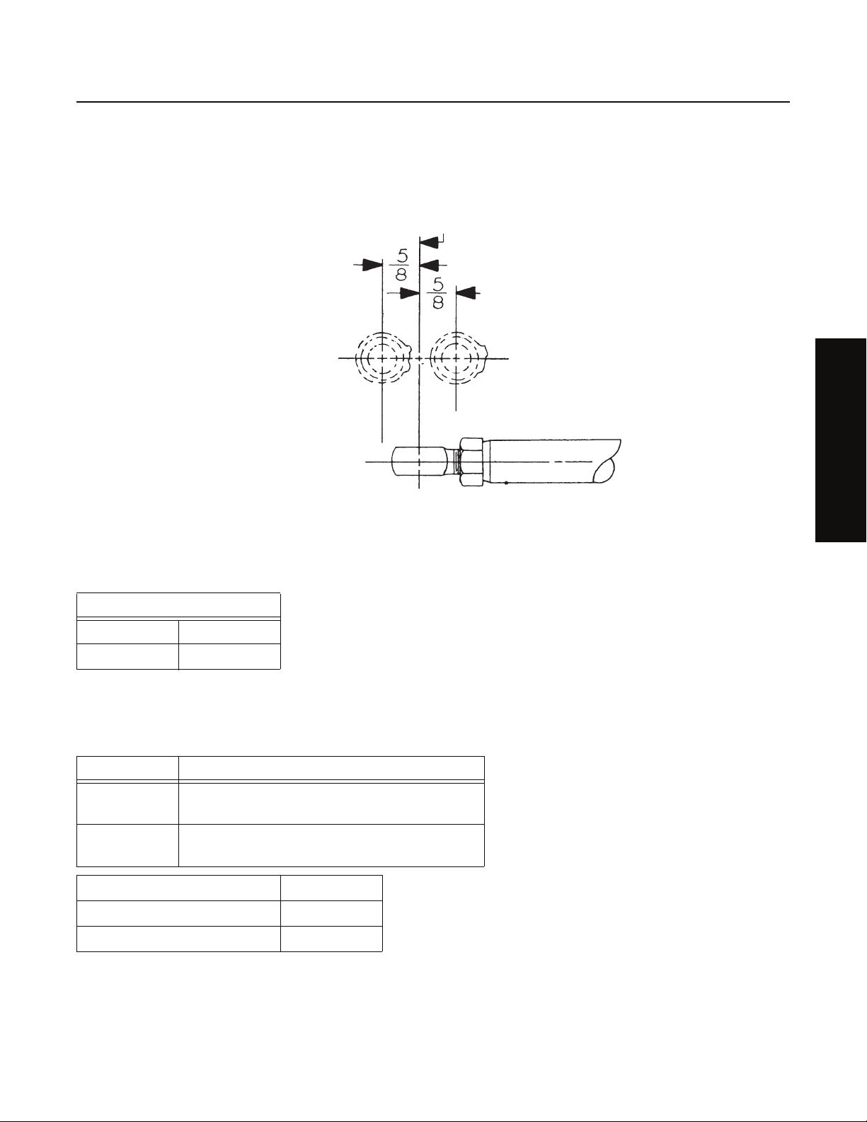
Mountings
Front bearing cover machined for trunnion mounting.
Four 5/8" diameter mounting studs, two on each side of case.
Power Take-OFF
Bottom SAE Standard 6-bolt, 30 tooth, 5P gear on left coun-
tershaft turning at .993 input shaft speed.
Top SAE Standard 8-bolt, 30 tooth, 5P gear on right coun-
tershaft turning at .993 input shaft speed.
Weight 330 pounds
Oil Capacity 12 pints
Installation length 16-3/16 inches
3
Page 6

Lubrication
Lubrication Specifications
Note: For a list of Eaton Approved Synthetic Lubricants, see TCMT-0021 the list of approved lubricants and TCMT-0021 the list of
lube intervals, or call 1-800-826-HELP (4357). Recommended lubricants for the 2-A-92 are currently the E500 and the E250,
which list a mileage, a year, and a hour change interval.
Note: The use of lubricants not meeting these requirements will affect warranty coverage.
Note: Additives and friction modifiers must not be introduced.
Note: Never mix engine oils and gear oils in the same transmission.
Buy from a reputable dealer
For a complete list of approved and reputable dealers, write to: Eaton Corporation, Worldwide Marketing Services, P.O. Box 4013,
Kalamazoo, MI 49003
Transmission Operating Angles
If the transmission operating angle is more than 12 degrees, improper lubrication will occur. The operating angle is the transmission mounting angle in the chassis plus the percent of upgrade (expressed in degrees). For operating angles over 12 degrees, the
transmission must be equipped with an oil pump or cooler kit to insure proper lubrication.
Mixing of Oil Types
CAUTION: Never mix engine oils & gear oils in the same transmission.
Engine oils and gear oils may not be compatible; mixing can cause breakdown of the lubricant and affect component performance.
When switching between types of lubricants, all areas of each affected component must be thoroughly flushed.
Operating Temperature
Oil Coolers
Kit K-1702 includes the pump, cooler and accesories to convert the AT-1202.
4
Page 7

Maintenance
Preventative Maintenance Check List
The following maintenance checks can be made without removing the transmission from the chassis. Items 1 through 5 can be
performed without any prior mechanical work; items 6 through 8 require the dropping of the output driveline and the input driveline where possible.
1. Oil Leaks
• Make visual checks for oil leakage from mainshaft openings, gaskets at bearing covers, top cover, and from front rear
shifting bar bores. Check drain plugs for losseness.
2. Gear Lubricant
• Remove filler plug in right side and check oil level at regular service intervals.
• Change oil at specified intervals, using grade and type recommended.
Note: See Lubrication section for inspection, oil type, grade, and oil capacity.
3. Gear Shift Lever and Linkage
• Check the auxiliary gear shift lever for wear at mounting.
• Check shifting linkage for wear and looseness.
• Check to make sure exact neutral position of auxiliary gear shift lever corresponds to neutral position of auxiliary shifting
bar.
General Information
4. Capscrews and Nuts
• Check capscrews in top cover and bearing covers for looseness which might be the cause of oil leakage.
• Check nuts on rear support bracket or plate for looseness.
5. Mountings
• Check mounting bolts and nuts for looseness.
6. Universal Joint Companion Flange Retaining Nuts
• With output driveline dropped, and front driveline dropped, where possible, check nuts for looseness. Tighten to recommended torque.
7. Splines on Shafts
• Check input and output shafts for wear from movement and chucking action of universal joint companion flange.
8. Mainshaft Rear Bearing
• Pry upward against output shaft to check radial clearance of mainshaft rear bearing.
5
Page 8

Tools
Tool Reference
Some illustrations in this manual show the use of specialized maintenance tools. These tools are recommended for transmission
repair as they make repair easier, faster, and prevent costly damage to such critical parts as bearings and sleeves.
Listed below are charts which list these specialized tools, the tool name and how it can be obtained.
General Tools
Tool Purpose
0-100 lbs.ft. 1/2" drive Torque Wrench General torquing of fasteners.
0-600 lbs.ft. 3/4" or 1" drive Torque Wrench Torquing of output nut.
Snap Ring Pliers - large standard external To remove snap rings at the auxiliary drive gear, input shaft
bearing, and countershaft.
Rolling Head (Crow’s foot) prybar To remove the auxiliary drive gear bearing.
Aftermarket Tools
Tool Purpose Eaton Part Number
Seal Driver Kit To install seal K-2413
Special Tools
Reference Number Tool Purpose G and W Tool Number Great Lakes Tool Num-
ber
Seal Driver Used to install the oil
seals in the front and
rear bearing cover
housings.
Bearing Driver Used to install the input
shaft and output shaft
bearings.
Bearing Driver Used to install the
countershaft bearings.
Specialty Tool Manufacturers
Below are the addresses and phone numbers of the companies that make tools specifically for Eaton®Fuller® transmissions:
G and W Tool Company
1105 E. Louisville, Broken Arrow, OK 74012-5724, Phone: 800-247-5882, or 918-258-6881
Great Lakes Tool
8530 M-89, Richland, MI 49083, Phone: 800-877-9618, or 269-629-9628
G-112
6
Page 9

Torque
Torque Ratings
Recommended torque ratings, location and thread sizes of capscrews and nuts are listed below. Capscrew lengths are given for
reference purposes as a guide for installation at proper locations.
Correct torque application is extremely important to assure long transmission life and dependable performance. Over-tightening
or undertightening can result in a loose installation and in many instances, cause damage to transmission gears, shafts and bearings. Do not torque capscrews dry.
Capscrews
Location Quantity Thread Size and Length Torque Rating Foot-Pounds
PTO cover, large 8 7/16 - 14x 1 50 - 65 lbs. ft.
PTO cover, small 6 3/8 - 16x 3/4 18-23 lbs. ft. (12-15 lbs. ft.
with oil filter)
General Information
Countershaft Front Bearing
Covers
Countershaft Rear Bearing
Covers
Rear Plate to Front Case 16 3/8 - 16x 1 - 1/2
Rear Bearing Housing 5 3/8 - 16x 3
Shift Bar Housing 4 3/8 - 16x 1 - 1/4
83/8 - 16x 1
83/8 - 16x 3
1 3/8 - 16x 3 35-45 lbs. ft.
23/8 - 16x 2
1 3/8 - 16x 3 eslock
Nuts
Location Quantity Thread Size and
Length
Mounting Studs 4 5/8 - 18 170 - 185
Front Bearing
Housing
Companion
Flanges or
Yokes
61/2 - 20
2 2 3/4 - 16 450 - 500
Torque Rating
Note: Installing the capscrews with more than 23 lbs. ft. of torque will force the corners of the PTO cover away from the case with
resultant oil leakage.
7
Page 10
Removal and Disassembly
General Instructions for Disassembly
Important: Read this section before starting the detailed disassembly procedures.
It is assumed in the detailed disassembly instructions that the transmission has been removed from the chassis, the lubricant has
been drained, the parking brake removed, if so equipped, and both universal joint companion flanges have been removed.
Follow each procedure closely in each section, making use of both the text and pictures. Use certain precautions, as listed below,
during disassembly.
Cleanliness
• Provide a clean place to work. It is important that no dirt or foreign material enters the unit during repairs. The outside
of the unit should be carefully cleaned before starting the disassembly. Dirt is abrasive and can damage highly polished
parts such as bearings, sleeves, and bushings.
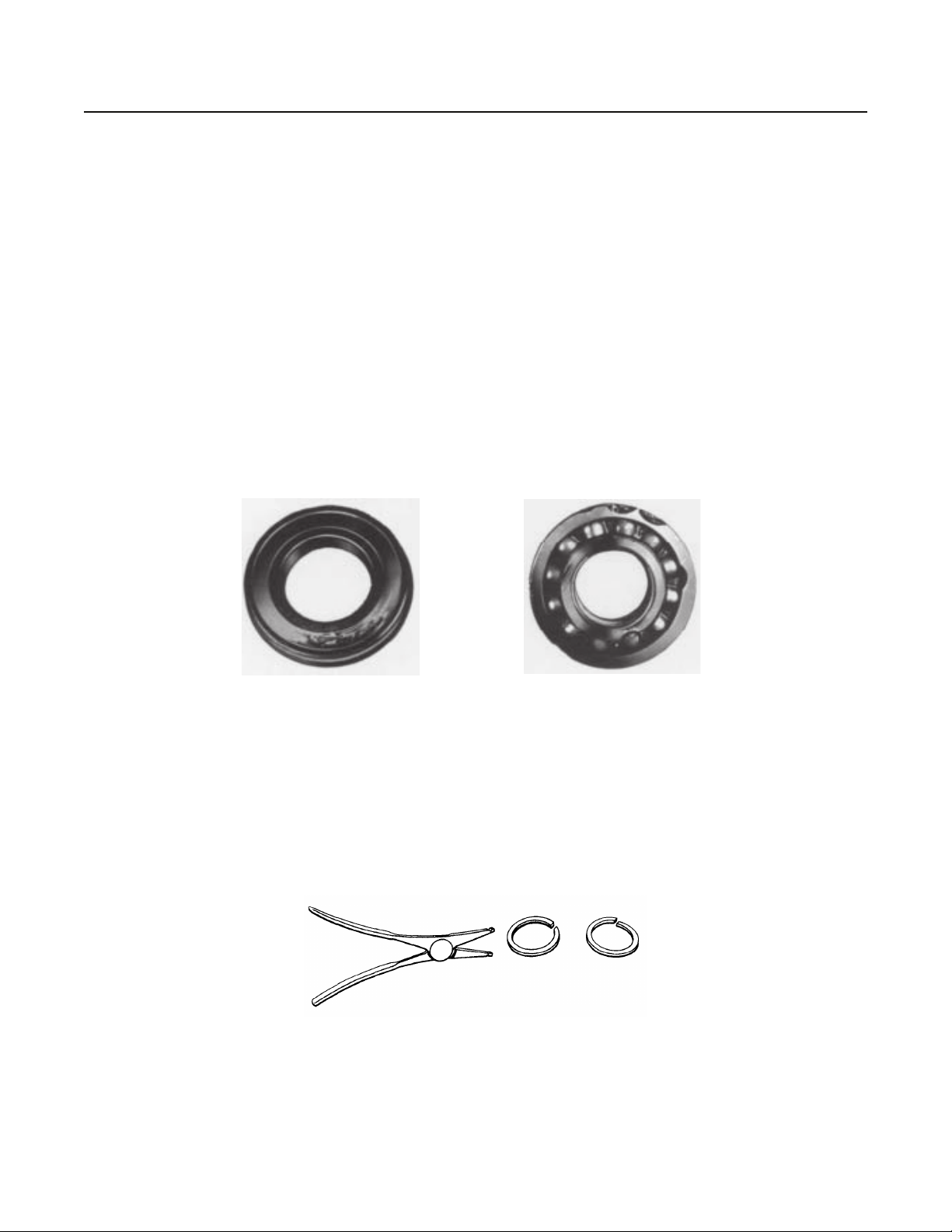
Bearings
• Carefully wash and re-lubricate all bearings as removed and protectively wrap until ready for use. Remove all bearings
with pullers designed for this purpose. Do not remove bearings with hammer and punch.
Bearing removed with punch,
damaged shield.
When Driving
• Apply force to shafts, bearings, and housings with restraint. Movement of some parts is restricted. Do not apply force
after the part being driven stops solidly. Use soft hammers, soft bars, and mauls for all disassembly work.
Snap Rings
• Remove snap rings with pliers designed for this purpose. Rings removed in this manner may be reused.
Bearing removed with
chisel, damaged outer race.
8
Page 11
How to Remove the Companion Flanges or Yokes
Special Instructions
None
Special Tools
• Typical service tools
Procedure -
Removal and Disassembly
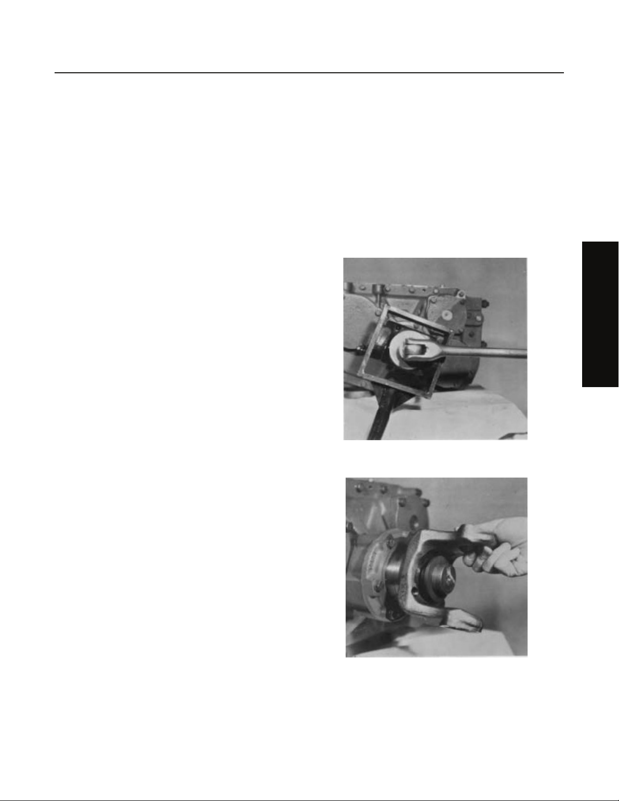
1. Brace against the yoke or flange on each shaft and use a
large breaker bar to remove the elastic stop nut from each
shaft.
2. Remove the washer and flange or yoke from each shaft.
Note: If a special tool is not available, the stop nuts may be
removed by putting the transmission in direct gear,
installing a breaker bar on the stop nut of both input
and output shaft and removing the nuts by bracing
them against each other.
Removal and Disassembly
9
Page 12

Removal and Disassembly
How to Remove the Rear Plate from the Front Case
Special Instructions
None
Special Tools
• Typical service tools
Procedure -
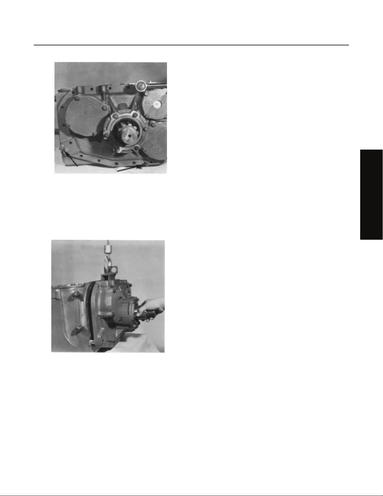
1. Loosen the jam nut and turn the rod end from the end of the
shift bar.
2. Turn out the 19 capscrews attaching the rear plate to the
front case.
10
Page 13
Removal and Disassembly
3. Insert three puller screws in the three tapped holes in the
mounting flange of the rear approximately 1/2 to break the
gasket.
4. Attach a chain hoist to the rear plate and move the plate
evenly to the rear and off the front case dowel pins. Mount
the rear plate in a vise in the upright position.
Removal and Disassembly
11
Page 14
Removal and Disassembly
14
2
12
1
13
7
6
3
4
5
9
8
15
10
11
16
61
61
17
How to Remove the Shifting Control Assembly With Air
Special Instructions
None
Special Tools
• Typical service tools
1. O-ring
2. Shift Cylinder
3. Shift Piston Assembly
4. O-ring
5. Roll Pin
6. O-ring
7. Yoke Bar
8. Cylinder Cover
9. Gasket
11. Capscrew
12. Shift Yoke
13. Lockscrew
14. Gasket
15. Elbow
16. Air Valve
17. Air Valve
18. Valve Plate
10. Lockwasher
12
Page 15

Removal and Disassembly
Procedure -
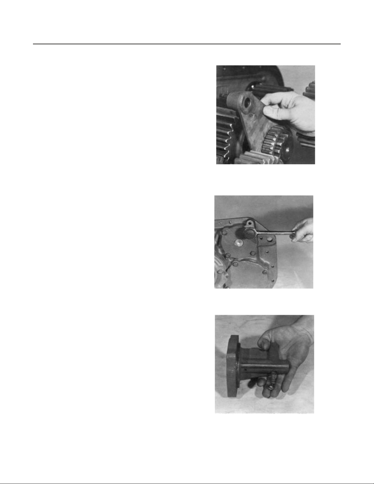
1. Cut the lockwire and remove the yoke lockscrew.
2. Remove the spacer from the front of the shift bar.
Removal and Disassembly
3. Put a rag over the bore in the shift bar housing to prevent
loss of the tension spring and ball and pull the shift bar
sharply forward and from the housing.
13
Page 16
Removal and Disassembly
4. Remove the yoke from the sliding clutch and remove the
sliding clutch from the splines of the output shaft.
5. Turn out the four capscrews attaching the shift bar housing
to the rear plate and remove the housing.l
6. Tip the housing to remove the tension spring and ball.
14
Page 17
Removal and Disassembly
1
2
3
4
5
13
7
8
10
9
11
6
12
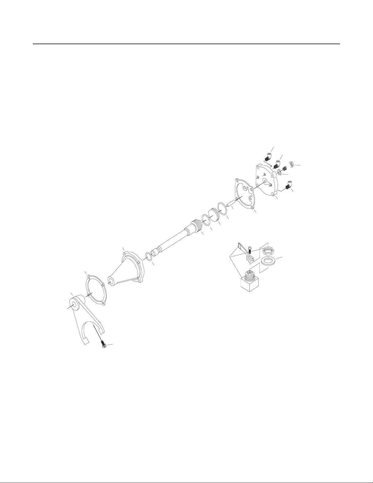
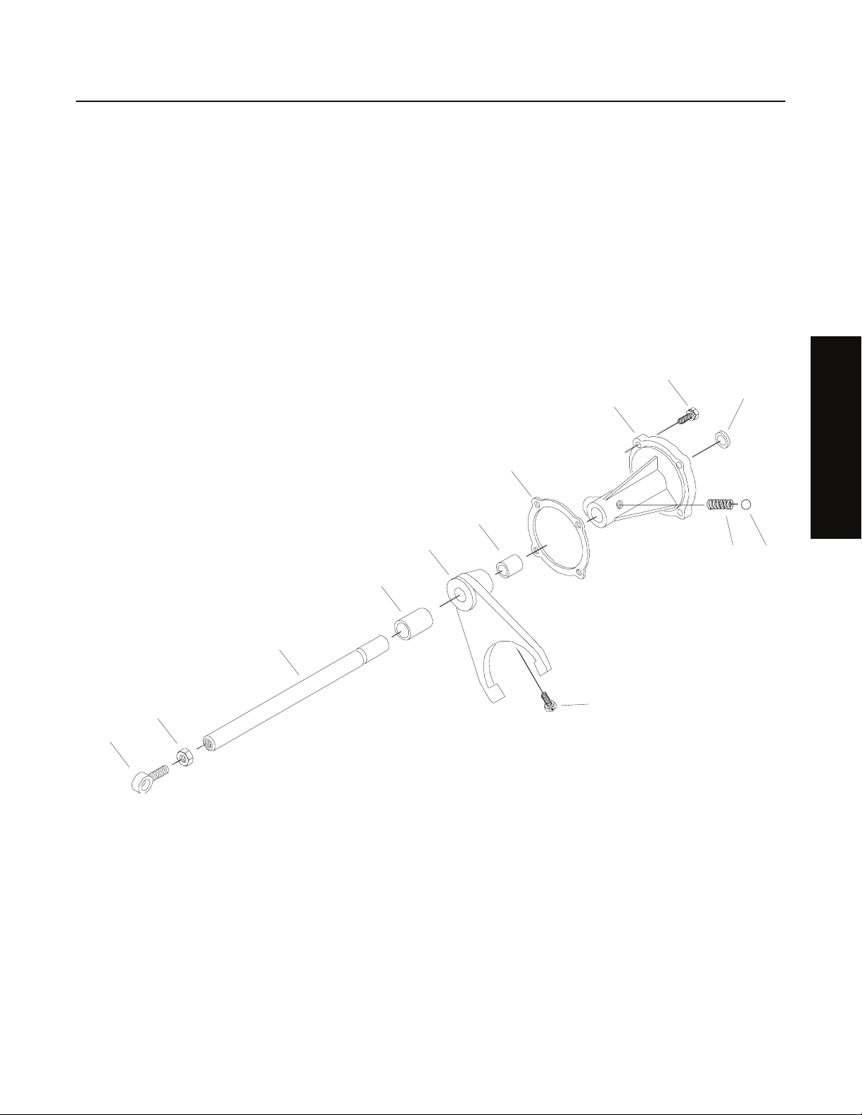
How to Remove the Shifting Control Assembly Without Air
Special Instructions
None
Special Tools
• Typical service tools
Removal and Disassembly
10
1. Eye Rod end
2. Nut
3. Yoke Bar
4. Spacer
5. Shift Yoke
6. Lockscrew
7. Gasket
8. Shift Cylinder
13
11
12
9. Plug
10. Capscrew
11. Spring
12. Steel Ball
13. NLA-Spacer
15
Page 18

Removal and Disassembly
Procedure -
1. Cut the lockwire and remove the yoke lockscrew.
2. Remove the spacer from the front of the shift bar.
3. Put a rag over the bore in the shift bar housing to prevent
loss of the tension spring and ball and pull the shift bar
sharply forward and from the housing.
4. Remove the yoke from the sliding clutch and remove the
sliding clutch from the splines of the output shaft.
16
Page 19

5. Turn out the four capscrews attaching the shift bar housing
to the rear plate and remove the housing.l
Removal and Disassembly
6. Tip the housing to remove the tension spring and ball.
Removal and Disassembly
17
Page 20

Removal and Disassembly
How to Remove the Countershaft Assemblies
Special Instructions
None
Special Tools
• Typical service tools
1
1. Bearing
2. Welded Countershaft
3. Bearing
4. Snap Ring
3
2
4
Procedure -
1. Use a three-jaw puller or equivalent to remove the front
bearing from each countershaft.
18
Page 21

Removal and Disassembly
2. Remove the two countershaft rear bearing covers.
3. Remove the snap ring from the rear of each countershaft.
Removal and Disassembly
4. Use a soft bar and maul to drive the countershaft assemblies
forward and from the rear bearings.
19
Page 22

Removal and Disassembly
5. Use a soft bar to tap the bearings to the rear and from the
rear plate bores.
20
Page 23

Removal and Disassembly
How to Remove the Output Shaft and Reduction Gear Assembly
Special Instructions
None
Special Tools
• Typical service tools
1
1. Sliding Clutch
2. Mainshaft
3. Reduction Gear
4. Bearing
5. Snap Ring
6. Washer
7. Nut
5
3
4
6
7
Removal and Disassembly
2
Procedure -
1. Use a soft bar and maul to drive the output shaft forward and
from the rear bearing assembly.
21
Page 24

Removal and Disassembly
2. Remove the bearing inner spacer from the shaft.
3. Remove the snap ring from the groove in the I.D. of the reduction gear.
4. Use a soft bar to tap the reduction gear from the output
shaft.
5. Using the inner race of the reduction gear bearing as a base,
press the rear bearing front cone from the output shaft. This
will free the reduction gear bearing and washer.
22
Page 25

How to Remove the Rear Bearing Assembly
Special Instructions
None
Special Tools
• Typical service tools
Removal and Disassembly
Removal and Disassembly
Procedure -
1. Turn out the six capscrews attaching the rear bearing housing to the rear plate.
23
Page 26

Removal and Disassembly
2. Remove the rear bearing housing, rear bearing cone and
speedometer drive gear or replacement spacer from the rear
plate.
3. Use a soft bar to tap the front bearing cup and outer spacer
forward and from the rear plate bore.
24
4. From inside the plate, tap the rear bearing cup to the rear and
from the rear plate bore.
Note: If necessary, remove the oil seal from the rear bearing
housing with a hammer and punch. Removal procedure will damage the seal and removal should not be
attempted unless replacement of the seal is planned.
Page 27

How to Remove the Input Shaft and Drive Gear Assembly
Special Instructions
None
Special Tools
• Typical service tools
Removal and Disassembly
Removal and Disassembly
Procedure -
1. Remove the snap ring from the groove in the rear of the coupling shaft.
2. Pull the drive gear to the rear and from the splines of the
coupling shaft.
25
Page 28

Removal and Disassembly
3. Use a soft bar and maul to drive the input shaft to the rear
and from the front bearing assembly.
4. Remove the snap ring from the input shaft.
5. Press the input shaft rear bearing from the shaft.
26
Page 29

6. Mount the input shaft in a vise with the threaded end down
and use a Allen wrench to remove the Allen screw located in
the hub of the coupling shaft. It will be necessary to turn the
Allen wrench with a crescent or open end wrench.
Note: Do not install the input shaft in the vise by the threads.
7. Remove the coupling shaft from the input shaft.
Removal and Disassembly
Removal and Disassembly
27
Page 30

Removal and Disassembly
How to Remove the Front Bearing Housing Assembly
Special Instructions
None
Special Tools
• Typical service tools
Procedure -
1. Remove the six nuts attaching the housing to the front case
and pull the housing from the studs.
28
Page 31

Removal and Disassembly
2. If necessary to remove the oil seal or front bearing
3. If necessary, remove the shifting bar packing and packing
retainer from the front shifting bar bore in the case and remove the Welch plug from the rear shifting bar bore.
Removal and Disassembly
4. If necessary, remove the pipe plug from the bore in the top
of the case.
29
Page 32

Removal and Disassembly
How to Disassemble the Front Case
Special Instructions
None
Special Tools
• Typical service tools
Procedure -
1. For reassembly purposes, remove the two countershaft
front bearing covers.
Note: Remove PTO gear covers, filler and drain plugs,
breather and miscellaneous items as necessary. Removal of the seal and scraper in the shift bar bore will
most likely damage the parts and removal should not
be attempted unless replacement of the parts if
planned.
30
Page 33

Assembly and Installation
Inspection and General Instructions for Reassembly
Before reassembling the transmission, the individual parts should be carefully checked to eliminate those damaged from previous
service. This inspection procedure should be carefully followed to insure the maximum of wear life from the rebuilt unit.
The cost of a new part is generally a small fraction of the total cost of downtime and labor, should the use of a questionable part
make additional repairs necessary before the next regularly scheduled overhaul.
Recommended inspection procedures are set forth in the check list which follows:
Bearings
• Wash all bearings in clean solvent. Check balls, rolls, and races for pits and spalled areas. Check the bearing shields for
damage. Replace bearings which are pitted, spalled, or damaged.
• Lubricate bearings and check for axial and radial clearances. Replace the bearings with excessive clearances.
• Check fits of the bearings in the case bores. If the outer races turn freely in the bores, the case should be replaced.
Gears
• Check the operating gear teeth for pitting on the tooth faces. Gears with pitted teeth should be replaced.
• Check all engaging gear teeth both internal and external. Gears with teeth worn, tapered, or reduced in length from clash-
ing in shifting should be relpaced.
• Check the radial clearance of the bushed gear. If excessive radial clearance is found, replace the bushing.
Splines
• Check the splines on all the shafts for wear. If sliding gears or companion flanges have worn into the sides of the splines,
shafts, or gears they should be replaced.
General Information
Gray Iron Parts
• Check all gray iron parts for cracks and breaks. Replace or repair parts found to be damaged. Heavy castings may be
welded or brazed providing the cracks do not extend into the bearing bores or bolting surfaces.
31
Page 34

Assembly and Installation
Washers
• Check the surfaces of the washers. Washers scored or reduced in thickness should be replaced.
Shifting Bar Assembly
• Check the yoke for alignment and straighten if sprung.
• Check the lockscrew in the yoke and tighten and rewire if found loose.
• Check the neutral notches of the shifting bar for wear from the tension spring ball.
• Check yoke for wear at pads and replace if worn.
• Check yoke for excessive wear and replace if worn.
Bearing Covers
• Check the covers for wear from the thrust of adjacent bearing. Replace the covers that are worn or grooved from the
thrust of the bearing outer race.
• Check bores of covers for wear and replace those worn oversize.
Oil Seals
• Check the lip seal in the front and rear for wear, cracks, or breaks. Check the tension of the lip on the sealed surface.
Replace seals if the lip is damaged or shows no wiping action from the lip due to a lack of tension.
32
Page 35

Assembly and Installation
General Instructions for Reassembly
Make sure the interior of the case and the other housings are clean. It is important that dirt be kept out of the transmission during
reassembly. Dirt is abrasive and can damage polished surfaces of sleeves, bushings, and bearings. Use certain precautions, as
listed below, during reassembly.
Gaskets
• Use new gaskets throughout the transmission as it is being rebuilt. Make sure all gaskets are installed. Omission of gas-
kets can result in oil leakage or improper stack-up of bearing covers. Seat gasket on part to be installed with adhesive to
hold in place during installation.
Capscrews
General Information
• To prevent oil leakage, use adhesive sealant on all capscrews. See Torque Ratings chart on page 6 for recommended
torque applications.
Initial Lubrication
• Coat gear bushings, washers, and splines of mainshaft with Lubriplate during installation to provide initial lubrication,
thus preventing scoring and galling.
Bearings
• Use of flanged-end bearing drivers is recommended for installation of bearings. These drivers apply equal force to both
inner and outer races of the bearing, preventing damage to the balls along with maintaining the correct bearing aligment
with the shaft and bore. If a tubular or sleeve driver is used, apply force evenly to the inner race and drive through the
tubing of the correct diameter.
33
Page 36

Assembly and Installation
Universal Joint Companion Flanges
• Make sure the companion flanges are pulled tightly into place with the retaining nuts. Failure to tighten the retaining nuts,
or omission of parts between flanges and bearings will premit the shafts to move axially, with resultant damage to the
pilot bearing, mainshaft, and drive gear.
• When installing the companion flanges, tighten the retaining nuts with 400-450 lbs. ft. of torque if elastic stop nut is used.
With slotted type nut, use 250 to 300 lbs. ft. of torque. Make sure the speedometer gear has been installed between the
rear flange and the bearing. If the speedometer gear is not used, a replacement spacer of the same width must be used.
Make sure the speedometer gear washer is installed between the speedometer gear and bearing.
Oil Filling
• Remember to fill the transmission with the correct amount of lubricant. Refer to TCMT-0021 for lubrication information.
Sliding Clutch
• Check yoke and yoke slot in sliding clutch for extreme wear or discoloration from heat.
• Check engaging teeth of sliding clutch for partial engagement pattern.
34
Page 37

Assembly and Installation
How to Assemble the Input and Coupling Shaft
Special Instructions
Mount the input shaft in a vise with the threaded end down. Do not secure the input shaft in the vise by the threads.
Special Tools
• Typical service tools
Procedure -
1. Apply a drop of Grade AVV Loctite to the threads of the Allen
head screw.
2. Install the coupling shaft in the input shaft with the large
bore facing up.
Assembly and Installation
3. Secure the coupling shaft to the input shaft with the Allen
head screw. It will be necessary to turn the Allen wrench
with an open-end or cresent wrench.
35
Page 38

Assembly and Installation
How to Assemble the Front Bearing Housing Assembly
Special Instructions
None
Special Tools
• Typical service tools
Procedure -
1. Install the rear bearing on the input shaft against the shoulder on the shaft.
Note: Heating of the bearing will faciliate installation. Do not
heat the bearing over 275 °F.
2. Install the snap ring in the groove on the input shaft.
3. Install the front bearing in the bearing housing with a bearing driver or by tapping carefully on the bearing inner race
with a soft bar.
36
Page 39

Assembly and Installation
4. Install the front bearing retaining snap ring in the groove in
the housing. Make sure that the snap is in the groove and not
just against the shoulder in the housing bore.
5. Use an oil seal driver to install the front oil seal. The side of
the oil seal with the seam should face into the housing, and
the front of the seal should be flush with the face of the
housing.
Assembly and Installation
6. Install the front bearing housing on the front case studs with
the oil feed port on the mounting surface of the bearing
housing aligned with the oil port in the front of the case. Secure with the six nuts and lockwashers.
37
Page 40

Assembly and Installation
7. From inside the case, start the input shaft assembly into the
bearing housing bore with a soft bar. Use a soft bar and maul
to drive the shaft forward until the rear bearing seats against
the shoulder in the bore.
8. Install the drive gear on the shaft with the clutching teeth
facing towards the rear of the case.
9. Install the snap ring in the groove on the coupling shaft.
Note: If previously removed, reinstall the two PTO covers, all
plugs and the shift bar seal and scraper. Do not install
the two countershaft front bearing covers at this time.
38
Page 41

How to Assemble the Output Shaft and Reduction Gear
Special Instructions
None
Special Tools
• Typical service tools
Procedure -
Assembly and Installation
1. Install the reduction gear bearing in the hub of the reduction
gear with snap ring in the bearing facing up. Use a bearing
driver or tap carefully on the outer race of the bearing with a
soft bar.
2. Install the snap ring in the groove in the hub of the reduction
gear.
Assembly and Installation
3. Mark any two teeth on the reduction gear and then mark the
two teeth directly opposite.
39
Page 42

Assembly and Installation
4. Place the output shaft on a bench with the threaded end up
and install the reduction gear on the shaft with the clutching
teeth of the gear facing down.
5. Install the washer on the shaft and against the gear with the
larger bevel on the ID of the washer facing down.
40
6. Install the bearing front cone on the shaft and against the
washer with the taper facing up.
Note: Heating of the bearing will faciliate installation. Do not
heat the bearing over 275°F.
Page 43

7. Install the bearing inner spacer on the shaft.
Assembly and Installation
Assembly and Installation
41
Page 44

Assembly and Installation
How to Install the Output Shaft and Rear Bearing Assembly
Special Instructions
None
Special Tools
• Typical service tools
Procedure -
1. Install the bearing front cup in the rear plate bore, taper facing up.
2. Place the bearing outer spacer on the front cup and tap evenly into the rear plate bore.
3. Place the bearing rear cup on the outer spacer and tap evenly
into the bore until the rear cup lip seats against the plate.
42
Page 45

Assembly and Installation
4. Place the rear plate over the output shaft assembly.
Note: If the rear cup lip moves away from the plate, hold the
lip in position against the plate by bolting a countershaft bearing cover on the plate mounting surface so
that an edge of the cover holds the lip of the bearing
cup against the rear plate.
5. Install th e bearing rear cone on the shaft, taper facing down.
Note: Heating of the bearing will facilitate installation. Do not
heat the bearing over 275°F.
6. If previously removed, install the oil seal in the rear bearing
housing flush with the surface, seam of the seal facing into
the housing.
Note: On units equipped with a speedometer driver gear, in-
stall the gear on the shaft prior to installation of the
rear bearing housing.
Assembly and Installation
43
Page 46

Assembly and Installation
7. Install the rear bearing housing on the rear plate with the six
retaining capscrews. The capscrew with the brass washer is
installed in the capscrew bore intersecting the speedometer
bore.
Note: The rear bearing housing may be installed with the
speedometer bore on either the left or right hand side
of the plate. Make sure that either notch in the mounting surface of the housing is lined up with the oil port
in the mounting surface of the plate.
44
Page 47

How to Time and Install the Countershaft Assemblies
Special Instructions
None
Special Tools
• Typical service tools
Procedure -
Assembly and Installation
1. Mark the tooth which is stamped with an "O" on the reduction
gear of each countershaft.
2. Place one of the countershaft assemblies in position inside
the plate with the marked tooth meshed between two of the
marked teeth on the reduction gear.
Assembly and Installation
45
Page 48

Assembly and Installation
3. Use a soft bar to start the countershaft rear bearing on the
shaft and in the case bore.
4. Use a bearing driver and maul to comlete installation of the
countershaft rear bearing. Repeat the procedure for installation of the remaining countershaft.
5. Install the snap ring in the groove at the rear of each counershaft.
6. Install the two countershaft rear bearing covers.
46
Page 49

How to Install the Shifting Controls
Special Instructions
None
Special Tools
• Typical service tools
Procedure -
Assembly and Installation
1. Install the tension spring in the bore of the shift bar housing.
2. Install the tension ball over the spring, and use a screwdriver
or equivalent to hold the tension ball down and insert the end
of the shift bar with the three notches into the housing until
the neutral (middle) notch is over the tension spring and
ball.
Assembly and Installation
47
Page 50

Assembly and Installation
3. Install the sliding clutch gear on the output shaft and place
the shift yoke in position with the long hub of the yoke facing
the rear plate.
4. Place ths shift housing and bar in position, passing the shift
bar through the yoke hub. Note that the tension spring housing faces to the outside of the plate.
5. Turn the shift bar until the lockscrew bore aligns with the
lockscrew bore of the shift yoke. A click will be heard when
the tension ball seats in the neutral notch.
48
Page 51

6. Install the yoke lockscrew. Tighten and lockwire securely.
7. Install the spacer on the shift bar and against the yoke with
the bevel on the ID of the spacer facing the yoke.
Assembly and Installation
Assembly and Installation
8. Secure the shift bar housing to the rear plate with the four
retaining capscrews. If previously removed, install the plug
in the end of the shift bar housing.
49
Page 52

Assembly and Installation
How to Install the Rear Plate
Special Instructions
None
Special Tools
• Typical service tools
Procedure -
1. Attach a chain hoist to the rear plate and move the plate
evenly into the front case, first guiding the shift bar into the
front case bore and then installing the rear plate bores on the
front case dowel pins. Turn the input shaft as necessary to
mesh with the countershaft assemblies.
2. Secure the rear plate to the front case with the 19 retaining
capscrews.
50
Page 53

Assembly and Installation
3. Use a soft bar to start the countershaft front bearings on the
shafts and into the case bores. Use a bearing driver to complete installation. The beveled ID of each bearing faces into
the case.
4. Install the two countershaft front bearing covers.
Assembly and Installation
51
Page 54

Assembly and Installation
How to Perform Final Installation of the Shifting Controls
Special Instructions
None
Special Tools
• Typical service tools
Procedure -
1. If previously removed, install the jam nut on the rod end and
turn the rod end into the end of the shift bar.
2. Set the rod end in the desired position and lock in place by
tightening the jam nut against the shift bar.
52
Page 55

How to Install the Companion Flange or Yoke
Special Instructions
None
Special Tools
• Typical service tools
Procedure -
Assembly and Installation
1. Install the yoke or flange on the input shaft and install the
washer and elastic stop nut on the threads of the input shaft.
2. On units not equipped with a speedometer drive gear, install
the spacer on the output shaft and in the rear bearing housing.
Assembly and Installation
3. Install the yoke or flange on the output shaft and install the
washer and elastic stop nut on the threads of the shaft.
53
Page 56

Assembly and Installation
4. Use the special tool to hold the yoke or flange in position and
torque the elastic stop nut on each shaft to 450-500 lbs. ft.
torque.
Note: If a special tool is not available, the stop nuts may also
be installed by putting the transmission in direct gear
and bracing against one shaft while torquing the stop
nut on the other shaft. Repeat the procedure for
torquing the opposite stop nut.
54
Page 57

Copyright Eaton Corporation, 2012.
Eaton hereby grant their customers,
vendors, or distributors permission
to freely copy, reproduce and/or
distribute this document in printed
format. It may be copied only in
its entirety without any changes or
modifications. THIS INFORMATION
IS NOT INTENDED FOR SALE OR
RESALE, AND THIS NOTICE MUST
REMAIN ON ALL COPIES.
Note: Features and specifications
listed in this document are subject to
change without notice and represent
the maximum capabilities of the
software and products with all options
installed. Although every attempt has
been made to ensure the accuracy of
information contained within, Eaton
makes no representation about the
completeness, correctness or accuracy
and assumes no responsibility for
any errors or omissions. Features and
functionality may vary depending on
selected options.
For spec’ing or service assistance,
call 1-800-826-HELP (4357) or visit
www.eaton.com/roadranger.
In Mexico, call 001-800-826-4357.
Roadranger: Eaton and trusted partners
providing the best products and services in the
industry, ensuring more time on the road.
Eaton Corporation
Vehicle Group
P.O. Box 4013
Kalamazoo, MI 49003 USA
800-826-HELP (4357)
www.eaton.com/roadranger
Printed in USA
Page 58

For parts or service call us
Pro Gear & Transmission, Inc.
1 (877) 776-4600
(407) 872-1901
parts@eprogear.com
906 W. Gore St.
Orlando, FL 32805
 Loading...