

Page 1

Troubleshooting Guide
Eaton Gen III Automated
Transmissions
TRTS0930 EN-US
January 2016
Ult raShift ®
AutoShift®
Page 2

Model:
F-5405B-DM3
F-6405B-DM3
FM-14D310B-LST
FM-15D310B-LST
FO-16D313E-LEP
FO-5406B-DM3
FO-6406A-AW3
FO-6406B -AW3
FO-8406A-AW3
FOM-16D313E-LEP
RTLO-14918A-AS3
RTLO-16913L-DM3
RTLO-16918A-AS3
RTO-10910B-DM3
RTO-12910B-AS3
RTO-12910B-DM3
RTO-14910B-AS3
RTO-14910B-DM3
RTO-14910C-AS3
RTO -16910B-AS3
RTO -16910B-DM3
RTO -16910C-AS3
RTO-18910B-AS3
F-5505B-DM3
F-6505B-DM3
RTLO -18918A-AS3
RTLO-20918A-AS3
RTLO-22918A-AS3
RTLOM-16913L-DM3
RTO -10910B-AS3
RTOM-16910B-DM3
Page 3

Page 4

T
RTS0930 Table of Contents
Table of Contents
General Information
Warnings and Cautions . . . . . . . . . . . . . . . . . . . . . . . . .1
Transmission Models. . . . . . . . . . . . . . . . . . . . . . . . . . .2
Diagnostic Procedures . . . . . . . . . . . . . . . . . . . . . . . . . .3
Fault Code Retrieval/Clearing . . . . . . . . . . . . . . . . . . . . .5
Retrieving Fault Codes Manually. . . . . . . . . . . . . . . 5
Clearing Fault Codes Manually . . . . . . . . . . . . . . . . 6
Retrieving Fault Codes with ServiceRanger . . . . . . 6
Clearing Fault Codes with ServiceRanger . . . . . . . . 7
Fault Code Isolation Procedure Index. . . . . . . . . . . . . . .8
Symptom-Driven Diagnostics Index. . . . . . . . . . . . . . .10
Product Diagnostic (PD) Mode . . . . . . . . . . . . . . . . . .11
Pretest Procedures
Electrical Pretest . . . . . . . . . . . . . . . . . . . . . . . . . . . . .12
TECU Power Harness . . . . . . . . . . . . . . . . . . . . . . 13
Preferred +12 Volt Connections . . . . . . . . . . . . . . 14
Preferred +12 Volt Connections . . . . . . . . . . . . . . 15
Preferred +24 Volt Connections . . . . . . . . . . . . . . 16
Preferred +24 Volt Connections . . . . . . . . . . . . . . 17
TECU Ignition Circuit . . . . . . . . . . . . . . . . . . . . . . 18
J1939 Data Link . . . . . . . . . . . . . . . . . . . . . . . . . . 19
J1939 Troubleshooting. . . . . . . . . . . . . . . . . . . . . 19
Electrical Pretest . . . . . . . . . . . . . . . . . . . . . . . . . . . . .20
Power-Up Sequence Test. . . . . . . . . . . . . . . . . . . . . . .22
Fault Isolation Procedures
Fault Code 11 - No TECU Operation . . . . . . . . . . . . . . .30
Fault Code 12 - Improper ECU Configuration . . . . . . . .34
Fault Code 13 - J1939 Shift Control Device . . . . . . . . .38
Fault Code 14 - Invalid Shift Lever Voltage (without Park
Pawl) . . . . . . . . . . . . . . . . . . . . . . . . . . . . . . . . . . . . . .42
Fault Code 14 - Invalid Shift Lever Voltage (with Park
Pawl) . . . . . . . . . . . . . . . . . . . . . . . . . . . . . . . . . . . . . .48
Fault Code 15 - HIL Shift Device Configuration
Fault Code 16 - High Integrity Link (HIL)
Fault Code 17 - Start Enable Relay (SER
Fault Code 21 - Auto Neutral Park Brake Switch. . . . . .74
Fault Code 22 - ABS CAN Message Fault . . . . . . . . . . .80
Fault Code 26 - Clutch Slip. . . . . . . . . . . . . . . . . . . . . .84
Fault Code 27 - Clutch Disengagement . . . . . . . . . . . .88
Fault Code 28 - Clutch System . . . . . . . . . . . . . . . . . . .92
Fault Code 29 - Remote Throttle Enable. . . . . . . . . . . .98
. . . . . .54
. . . . . . . . . . .62
) Circuit . . . . .70
Fault Code 31 - Momentary Engine Ignition Interrupt Re-
lay (MEIIR) Test . . . . . . . . . . . . . . . . . . . . . . . . . . . . .102
Fault Code 32 - Loss of Switch Ignition Power Test. .108
Fault Code 33 - Low Battery Voltage Supply . . . . . . .112
Fault Code 34 - Weak Battery Voltage Supply . . . . . .118
Fault Code 35 - J1939 Communication Link. . . . . . . .124
Fault Code 36 - J1939 Engine Message . . . . . . . . . . .130
Fault Code 37 - Power Supply . . . . . . . . . . . . . . . . . .136
Fault Code 41 - Range Failed to Engage. . . . . . . . . . .142
Fault Code 42 - Splitter Failed to Engage . . . . . . . . . .148
Fault Code 43 - Range Solenoid Valve . . . . . . . . . . . .154
Fault Code 44 - Inertia Brake Solenoid Coil . . . . . . . .160
Fault Code 45 - High Capacity (HCIB) Failure. . . . . . .166
Fault Code 46 - Splitter Direct and Indirect Solenoid Valve
170
Fault Code 51 - Rail Position Sensor . . . . . . . . . . . . .176
Fault Code 52 - Gear Position Sensor. . . . . . . . . . . . .182
Fault Code 56 - Input Shaft Speed Sensor . . . . . . . . .188
Fault Code 57 - Main Shaft Speed Sensor . . . . . . . . .194
Fault Code 58 - Output Shaft Speed Sensor . . . . . . . .198
Fault Code 61 - Rail Select Motor. . . . . . . . . . . . . . . .202
Fault Code 63 - Gear Select Motor . . . . . . . . . . . . . . .208
Fault Code 68 - Grade Sensor . . . . . . . . . . . . . . . . . .214
Fault Code 71 - Unable to Disengage Gear. . . . . . . . .218
Fault Code 72 - Failed to Select Rail. . . . . . . . . . . . . .224
Fault Code 73 - Failed to Engage Gear . . . . . . . . . . . .230
Fault Code 74 - Engine Speed Response Fault . . . . . .236
Fault Code 75 - Power Down In Gear . . . . . . . . . . . . .240
Fault Code 81 - Gear Engagement Detected . . . . . . . .244
Fault Code 83 - Shift Lever Missing . . . . . . . . . . . . . .248
Fault Code 84 - Shift Control
Fault Code 85 - Shift Control Device Incompatible. . .256
Fault Code 99 - Direction Mismatch . . . . . . . . . . . . . .260
Device Not Configured .252
2016.01.15
© 2016 Eaton. All rights reserved
i
Page 5

Table of Contents
T
RTS0930
Symptom Isolation Procedures
Up/Down Button Test. . . . . . . . . . . . . . . . . . . . . . . . .264
Start Enable Relay Contact Test. . . . . . . . . . . . . . . . .268
J1587 Data Link Test. . . . . . . . . . . . . . . . . . . . . . . . .276
Front Box Control Test. . . . . . . . . . . . . . . . . . . . . . . .282
AutoShift Will Not Engage a Gear from Neutral Test .288
UltraShift DM3 Will Not Engage a Gear from Neutral Test
296
UltraShift AW3 Clutch Engagement Test . . . . . . . . . .302
AutoShift AS3 Shift Complaint Test . . . . . . . . . . . . . .306
UltraShift DM3 Shift Complaint Test . . . . . . . . . . . . .316
UltraShift AW3 Shift Complaint Test . . . . . . . . . . . . .326
Shift Lever Back Light Test . . . . . . . . . . . . . . . . . . . . 334
Appendix
Connector Pin Descriptions . . . . . . . . . . . . . . . . . . . .340
Transmission Controller 38-Way (Vehicle Interface
Connector) . . . . . . . . . . . . . . . . . . . . . . . . . . . . . 340
Push Button Shift Control 30-Way Connector . . 341
Cobra Lever 8-Way Connector . . . . . . . . . . . . . . 341
Transmission Controller 38-Way (Eaton Supplied
Assembly) . . . . . . . . . . . . . . . . . . . . . . . . . . . . . 342
Wiring Diagrams . . . . . . . . . . . . . . . . . . . . . . . . . . . .343
UltraShift DM3 6-Speed Wiring Diagram with Analog
Shifter . . . . . . . . . . . . . . . . . . . . . . . . . . . . . . . . 343
UltraShift DM3 6-Speed Wiring Diagram with Push
Button Shifter. . . . . . . . . . . . . . . . . . . . . . . . . . . 345
UltraShift AW3 6-Speed Wiring Diagram with Analog
Shifter . . . . . . . . . . . . . . . . . . . . . . . . . . . . . . . . 347
UltraShift AW3 6-Speed Wiring Diagram with Push
Button Shifter. . . . . . . . . . . . . . . . . . . . . . . . . . . 349
AutoShift 10-Speed Wiring
Shifter . . . . . . . . . . . . . . . . . . . . . . . . . . . . . . . . 351
AutoShift 10-Speed Wiring
Button Shifter. . . . . . . . . . . . . . . . . . . . . . . . . . . 353
UltraShift 10-Speed Wiring Diagram with Analog
Shifter . . . . . . . . . . . . . . . . . . . . . . . . . . . . . . . . 355
UltraShift 10-Speed Wiring
Button Shifter. . . . . . . . . . . . . . . . . . . . . . . . . . . 357
UltraShift 13-Speed Wiring Diagram with Analog
Shifter . . . . . . . . . . . . . . . . . . . . . . . . . . . . . . . . 359
UltraShift 13-Speed Wiring
Button Shifter. . . . . . . . . . . . . . . . . . . . . . . . . . . 361
AutoShift 18-Speed Wiring
Shifter . . . . . . . . . . . . . . . . . . . . . . . . . . . . . . . . 363
AutoShift 18-Speed Wiring
Button Shifter. . . . . . . . . . . . . . . . . . . . . . . . . . . 365
Eaton Cobra Lever Wiring Diagram . . . . . . . . . . 367
Diagram with Analog
Diagram with Push
Diagram with Push
Diagram with Push
Diagram with Analog
Diagram with Push
OEM Shift Lever Wiring Diagram . . . . . . . . . . . . 368
Eaton Push Button Wiring Diagram . . . . . . . . . . 369
OEM J1939 Shift Input Device Wiring Diagram . 371
Proper Clutch Operation
Check For Proper Clutch Operation
Confirm Proper Clutch Adjustment and Clutch
Contact. . . . . . . . . . . . . . . . . . . . . . . . . . . . . . . . 373
Clutch Grease Interval Service Procedure . . . . . 374
Adapter Test Kit J43318 . . . . . . . . . . . . . . . . . . . . . . 375
. . . . . . . . . . . . . . . . . . . . . .372
. . . . . . . . . . 372
Brake
ii
© 2016 Eaton. All rights reserved
2016.01.15
Page 6

TRTS0930
!
!
Warnings and Cautions
General Information | Warnings and Cautions
Warning: Follow the specified procedures in the indicated
order to avoid personal injury
Caution: Follow the specified procedures in the indicated
order to avoid equipment malfunction or damage.
Note: Additional relevant information not covered in the
service procedure.
Before starting a vehicle:
• Ensure adequate fuel level
• Sit in the driver's
Place
•
•
shift lever in neutral
parking brake
Set the
seat
Before working on a vehicle or leaving the cab
with engine running:
• Ensure ignition is off while hands are within the
clutch housing area.
•
•
shift lever in neutral
Place
Set the
parking brake
When parking the vehicle or leaving the cab:
• Place shift lever in neutral
•Set the parking brake
Cauti
!
on: Do not release the parking brake or attempt to
select a gear until the air pressure is at the correct level.
To avoid damage to the transmission during
towing:
1. Place shift lever in neutral
Lift the drive wheels off of the ground or discon-
2.
nect the driveline
operate the vehicle if Alternator light is lit or if
Do not
gauges indicate low voltage.
Block the wh
•
eels
2016.01.15
© 2016 Eaton. All rights reserved
1
Page 7
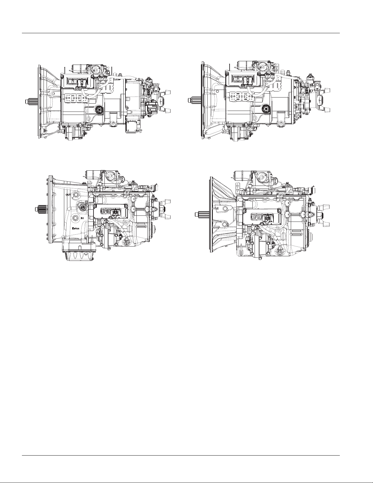
Transmission Models | General Information
Heavy-Duty 13-Speed DM3/LEP and 18-Speed AS3 Heavy-Duty 10-Speed AS3/DM3
Medium-Duty 6- and 5-Speed DM3 Medium-Duty 6-Speed AW3
Transmission Models
TRTS0930
2
© 2016 Eaton. All rights reserved
2016.01.15
Page 8

TRTS0930
Diagnostic Procedures
General Information | Diagnostic Procedures
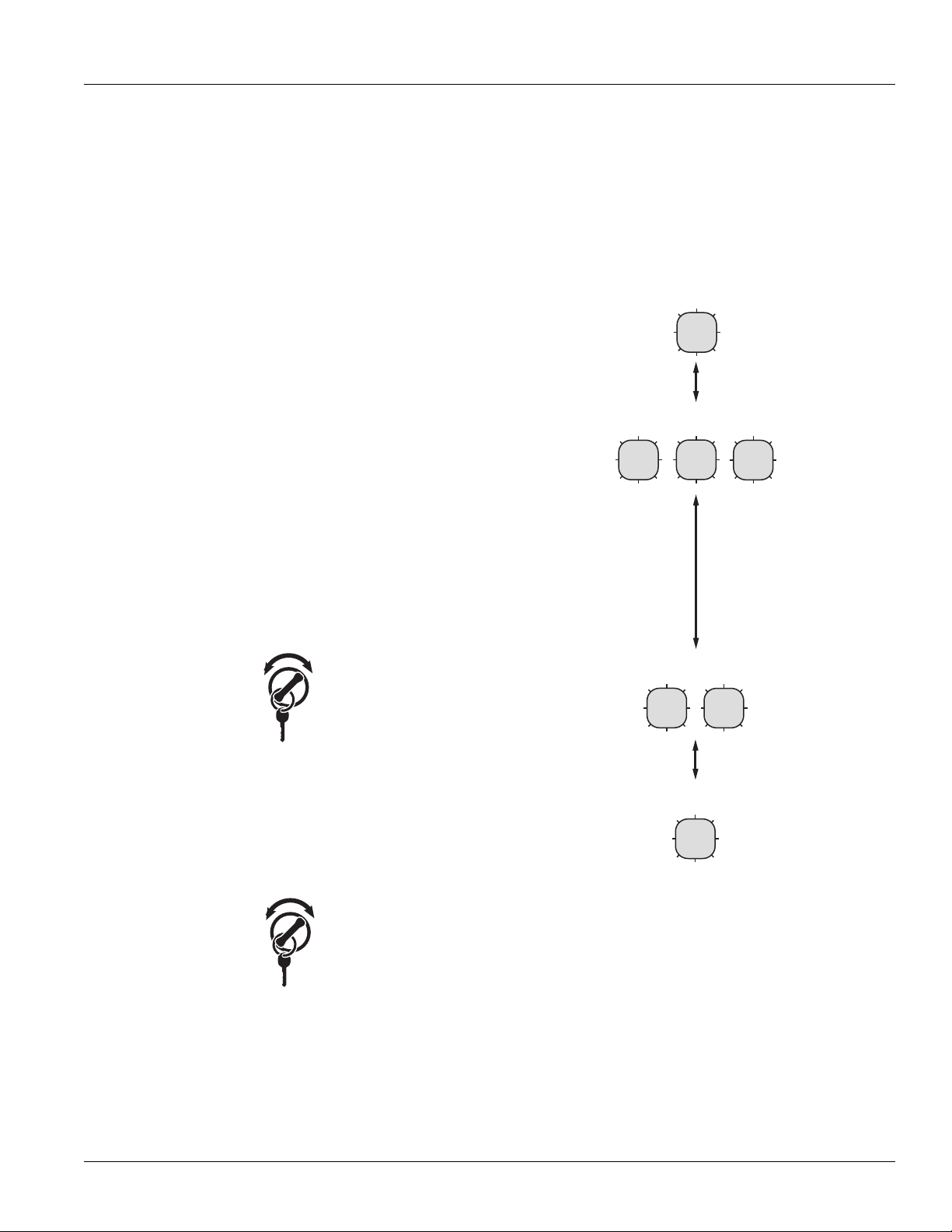
Purpose: Observe the transmission gear display.
A
1. Key on.
2. Observe gear display.
Note: An “88” may show up in the dash at key
This
indicates the Transmission Electronic
Control Unit (TECU) has completed
power-up. If the transmission and gear display power-up at the same time, you may
not see an “88”.
• If blank gear display, go to Step
• If “-” (1 dash) on gear display, go to Step D.
• If “--” (2 dashes) or “**” (2 stars) on gear dis-
play, go to Step D.
• “#” (gear number) on gear display
- Verify shift lever or push button is in neutral.
- Turn key off and wait 2 minutes.
- Hold clutch half way to the floor. (If
equipped)
- Turn key on.
- If problem continues, call 1-800-826-HELP
(4357)
B.
on.
Purpose: Confirm that the engine will crank and
B
start.
1. Attempt to start engine
• No engine crank, lever is in neutral an
displa
y is “N” (neutral). See
Relay
Contact Test” on page 268.
• No engine crank, lever is in neutral an
displa
y is blank. See “Power
T
est” on page 22.. If no problems found,
OEM for gear display problem.
to
• No engine crank and lever is
erify shift lever or push button is in neutral.
- V
- Turn key off and wait 2 minutes.
- Hold clutch half way to the floor. (If
equipped)
- Turn key on.
- If problem continues, call 1-800-826-HELP
(4357)
• Engine cranks and gear display is bl
OEM for gear display problem.
to
• Engine cranks and gear display is “N” (neutral), go to Step
C.
“Start Enable
-Up Sequence
d gear
d gear
refer
NOT in neutral.
ank. Refer
• Fault Code F on gear display, go to Step D.
• Neutral “N” on gear display, go to Step B.
2016.01.15
© 2016 Eaton. All rights reserved
3
Page 9
Diagnostic Procedures | General Information
TRTS0930
Purpose: Confirm the transmission will engage a
C
gear from neutral.
1. Attempt to engage a gear.
• If gear engaged and drives, go to Step E.
• If the gear display indicates a solid “gear num-
ber” but no drive or reverse, perf
B
ox Control Test” on page 282
• If unable to engage a g
an Au
toShift, perform “AutoShift Will
age a Gear from Neutral Test” on page 288
Eng
• If unable to engage a g
UltraShift DM3, perform “UltraShift DM
an
Not Engage a Gear from Neutral T
Will
page 29
• If unable to engage a g
an UltraShift AW3, perform “UltraShift AW3
Clutch Engagement Test” on page 302
6
ear and transmission is
ear and transmission is
ear and transmission is
orm “Front
Not
est” on
Purpose: Check for active or Inactive fault codes.
D
1. Check for active fault codes.
Note: If no problem found, refer to OEM for
oblem.
pr
• If codes are present, See “Fault Code Isol
Procedure
• If no codes and gear display is “-” (1 dash)
- Verify shift lever or push button is in neutral.
- Turn key off. Wait 2 minutes.
- Hold clutch half way to the floor. (If
3
equipped)
- Turn on key.
- If problem continues, call 1-800-826-HELP
(4357)
See “Front Box Control Test” on page 282.
• If no codes and gear display is“--” (2
or “**” (2
T
est” on page 22.
Index” on page 8.
stars), See “Power-Up
display
ation
dashes)
Sequence
Purpose: Drive vehicle and attempt to duplicate a
E
fault code.
1. Record and clear Inactive fault codes.
2. Drive vehicle and attempt to reset code.
• If no codes are present, test complete.
• If Inactive transmission component or
record codes an ca
Codes,
357).
(4
• If active transmission component or Fault
Codes, See “Fault
dex” on page 8.
In
Code Isolation Procedure
ll 1-800-826-HELP
Fault
4
© 2016 Eaton. All rights reserved
2016.01.15
Page 10
TRTS0930
Fault Code Retrieval/Clearing
General Information | Fault Code Retrieval/Clearing
Retrieving Fault Codes Manually
Retrieve fault codes by enabling the system’s self-diagnostic mode.
Note: You can also use a PC- based service tool, such as
ServiceRanger to retrieve fault codes.
1. Place the shift lever in neutral.
2. Set the parking brake.
3. Turn key on with engine off.
Note: If the engine is already running, you may still
retrieve codes; however, do not engage the
starter if the engine stalls.
4. To Retrieve Active Codes: Key on. Turn key off
on 2 times within five seconds ending with the key
on. After 5 seconds, the Service light begins flashing two-digit fault codes. If no faults are active, the
service light will flash code 25 (no codes). This is
also the procedure to enter, See “Product Diagnostic (PD) Mode” on page 11. for details.
Note: An “88” may show up in the dash at key on,
which is a normal power-up test of the display.
and
6. Observe the sequence of flashes on the service
light and record the codes. A 1- to 2-second pause
separates each stored code, and the sequence
automatically repeats after all codes have been
flashed.
1 Flash
SERVICE
Short
Code 13
pause
(1/2 sec)
3 Flashes
SERVICE
SERVICE
SERVICE
Long Pause
(3-4 sec)
2x
off
on
5. To Retrieve Inactive Codes: Turn key on. Turn the
key off and on 4 times within five seconds ending
with the key in the on position. After 5 seconds, the
Service light begins flashing two-digit fault codes.
If no faults are active, the service light will flash
code 25 (no codes).
4x
off
on
• Two digit fault codes will be displayed in the gear
display. Some vehicle may be equipped with a service light.
Code 21
2 Flashes
SERVICE
1 Flash
SERVICE
SERVICE
Short
pause
(1/2 sec)
2016.01.15
© 2016 Eaton. All rights reserved
5
Page 11

Fault Code Retrieval/Clearing | General Information
T
RTS0930
Clearing Fault Codes Manually
The following procedure clears all Inactive fault codes from
the TECU’s memory. Active fault codes are automatically
cleared when the fault has been corrected.
Note: You may use a PC-based service tool, such as Ser-
viceRanger, to clear fault codes.
1. Place shift lever in neutral.
2. Set parking brake.
.
with engine off.
6x
off
on
system to power
3. Turn key on
4.
Turn key off and on 6 times within 5 seconds ending with key on.
Note: If the codes have been successfully cleared, the
Service light will come on and stay on for five
seconds. The gear display will show 25 (no
codes).
5. Turn the key off and allow the
down
Retrieving Fault Codes with
ServiceRanger
This section determines if the TECU is communicating on
the vehicle's J1939 data link and if the component has set
any fault codes. Proper system operation requires the TECU
to communicate with other ECUs on the vehicle's J1939
data link.
Note: This procedure requires ServiceRanger 3.0 or later
and an approved RP1210A communications adapter
that supports J1939 communications.
Detecting Components
1. Connect the service PC to the
39 diagnostic port connector with
J19
RP1210A communications adapter.
2. Start the ServiceRanger program and verify
connection has
J1939 data link.
•
If the TECU is not detected by ServiceRanger,
proceed to the Electrical Pretest procedure
ensure the TECU
ponents are properly connected
J19
Viewing Fault Codes
View the Vehicle Fault Codes screen in ServiceRanger and
verify if any Active or Inactive codes have been set.
been established
39 data link.
vehicle's 9-way
an approved
that a
with the vehicle's
to
has power, and that all com-
the vehicle's
1. If an Active code is
information and
this manual for the Active code. Do not clear
in
code
s at this time.
2. If only Inactive codes are present, record the vehi-
cle fault information and clear all fault codes.
test the vehicle
present, record the vehicle fault
proceed to Diagnostic Proced
to verify proper operation.
ure
any
Road
6
© 2016 Eaton. All rights reserved
2016.01.15
Page 12

TRTS0930
Clearing Fault Codes with ServiceRanger
After all repairs have been made and the system is functioning normally, clear all vehicle codes before placing the vehicle back into service.
Clearing Fault Code
1. Connect the service PC to the vehicle and start ServiceRanger.
General Information | Fault Code Retrieval/Clearing
2. View the Ve
Clear All.
3.
Refresh the screen to ver
been cleared, and that no Active
hicle Fault Codes screen and select
ify all Inactive codes have
codes are present.
2016.01.15
© 2016 Eaton. All rights reserved
7
Page 13

Fault Code Isolation Procedure Index | General Information
Fault Code Isolation Procedure Index
Fault Codes SPN PID SID FMI Description
11 629 254 12 No ECU operation
12 629 254 13, 14 Improper ECU configuration
13 751 231 8, 11 J1939 Shift Control device
14
(without Park
Pawl)
14
(with Park
Pawl)
15 751 18 9 HIL Shift Device communication
16 625 248 2 High Integrity Link (HIL)
17 1321 237 3, 4, 14 Start Enable Relay Coil
21 70 70 14 Auto Neutral Park Brake Switch
22 563 49 9, 14 ABS CAN message fault
25 NO CODES
26 522 55 10 Clutch slip
27 788 55 7, 13 Clutch disengagement
28 788 52,55 3, 4, 5, 7 Clutch system
29 969 372 4, 5 Remote throttle enable
31 1485 218 2, 3, 4, 5, 14 Momentary Engine Ignition Interrupt Relay
32 158 43 2 Loss of Switch Ignition power test
33 168 168 4 Low Battery voltage supply
34 168 168 14 Weak Battery voltage supply
35 639 231 2 J1939 communication link
36 639 231 14 J1939 engine message
37 627 251 5 Power supply
41 768 35 7 Range failed to engage
41 769 36 7 Range failed to engage
42 770 37 7 Splitter failed to engage
42 771 38 7 Splitter failed to engage
43 768 35 3, 4, 5 Range High Solenoid Valve
43 769 36 3, 4, 5 Range Low Solenoid Valve
44 787 54 3, 4, 5 Inertia Brake Solenoid Coil
45 787 54 7 Intertia Brake performance
46 770 37 3, 4, 5 Splitter Direct Solenoid Valve
46 771 38 3, 4, 5 Splitter Indirect Solenoid Valve
51 60 60 2, 3, 4, 10 Rail Position Sensor
751 18, 19 2, 3, 4, 5 Invalid Shift Lever voltage
18, 19 2, 3, 4, 5 Invalid Shift Lever voltage
(will show “F” in display)
(MEIIR)
TRTS0930
8
© 2016 Eaton. All rights reserved
2016.01.15
Page 14

TRTS0930
General Information | Fault Code Isolation Procedure Index
Fault Codes SPN PID SID FMI Description
52 59 59 2, 3, 4, 7 Gear Position Sensor
56 161 161 2, 3, 4, 5,10 Input Shaft Speed Sensor
57 160 160 2, 3, 4, 5 Main Shaft Speed Sensor
58 191 191 2, 3, 4, 5, 6, 8 Output Shaft Speed Sensor
61 772 39 1, 5, 6, 12 Rail Select Motor
63 773 40 1, 5, 6, 12 Gear Select Motor
68 520274 227 14 Grade Sensor
68 520321 227 13, 14 Grade Sensor
71 560 60 7 Unable to disengage gear
72 772 59 7 Failed to select rail
73 781 58 7 Failed to engage gear
74 518 93 7 Engine speed response fault
74 898 190 7 Engine torque response fault
75* 560 60 14 Power down in gear
81 780 47 7 Gear engagement detected
83 751 18 14 Shift Lever missing
83 752 19 7, 12 Shift Lever missing
84 751 18 13 Shift Control device not configured
84 752 19 13 Park mechanism not calibrated
85 751 18 12 Shift Control device incompatible
99 781 58 14 Direction mismatch
* This code will only be set Inactive
• J1939 Source Address (SA) for Eaton transmissions is 3
• J1587 Module Identifier (MID) for Eaton transmissions is 130
2016.01.15
© 2016 Eaton. All rights reserved
9
Page 15
Symptom-Driven Diagnostics Index | General Information
TRTS093
Symptom-Driven Diagnostics Index
Symptom Isolation Procedure
Unable to shift transmission with Up/Down button Up/Down Button Test
Engine starting system complaint Start Enable Relay Contact Test
No J1587 communication J1587 Data Link Test
Gear display shows a dash Front Box Control Test
AutoShift will not engage a gear from Neutral AutoShift Will Not Engage a Gear from Neutral Test
UltraShift DM will not engage a gear from Neutral UltraShift DM Will Not Engage a Gear from Neutral Test
UltraShift AW3 will not engage a gear from Neutral UltraShift AW3 Clutch Engagement Test
AutoShift AS3 shift complaint AutoShift AS3 Shift Complaint Test
0
UltraShift
DM shift complaint UltraShift DM Shift Complaint Test
UltraShift AW3 shift complaint UltraShift AW3 Shift Complaint Test
Shift Lever back light does not work Shift Lever Back Light Test
10
© 2016 Eaton. All rights reserved
2016.01.15
Page 16

TRTS0930
Product Diagnostic (PD) Mode
Product Diagnostic (PD) Mode
PD Mode is used to help diagnose Inactive codes that may
have been set during normal driving. This diagnostic mode
increases the sensitivity of the fault sensing capability
This procedure tests loose, degraded and intermittent connections. Use the Active Fault Isolation Procedure to guide
you to the wiring and connectors that are associated with
the Inactive fault codes. Flex the wiring harness and connectors and attempt to recreate the fault after activating PD
Mode.
PD Mode is only to be used by a trained service technician
in an authorized dealer.
General Information | Product Diagnostic (PD) Mode
If the fault is detected during PD Mode the gear dis-
•
play will display the active fault. The warning to
will only sound
will stop when the fault is Inactive. The faul
stay in the gear display until the system is powered
down.
: Active codes set during PD Mode will not be
Note
stored as Inactive.
7. If a fault is detected, exit PD Mode and perf
corresponding Fault Isolation Procedure.
8.
To exit PD Mode, turn the key off.
when the fault is active and the tone
t will
orm the
ne
This procedure is to be used prior to performing fault isolation procedures for component-type codes when there are
no Active codes present.
To enter PD Mode:
Note: Vehicle will not start in PD Mode. You must turn vehi-
cle key off to exit PD Mode.
1. Vehicle must be stationary, engine off,
ng brake.
parki
2. Turn the key off and on 2 times, starting with
ending with
on and
Note: Dash may
mal power-up test of the display.
3. The gear display will flash a 25 then a solid
(Pro
duct Diagnostic Mode) and the
activated.
4.
The service light shall flash code 25 once indicatin
no cod
es. The service light shall
solid to
Act
indicate PD Mode
ive code is detected or PD Mode is exited.
key on.
display an 88 at key on. This is a nor-
until such time that an
set vehicle
key
PD
mode will be
then illuminate
PD Mode works with the following
Inactive codes:
11, 13, 14, 15,16, 17, 21, 22, 29, 33, 34, 35, 36, 43, 44, 46,
51, 52, 56, 57, 58, 61, 63, 74, and 99.
g
5. Refer to PD Mode section in Fault Isolation proce-
6. PD will remain in gear display until an active faul
2016.01.15
dure for the Inactive fault to be diagnosed.
has been set during the
procedure.
PD Mode fault is
t
olation
© 2016 Eaton. All rights reserved
11
Page 17

Electrical Pretest | Electrical Pretest Procedures
Electrical Pretest
Overview
The pretest does not relate to any specific fault code, but
must be completed before performing Fault Code Isolation
table procedures. The pretest verifies the batteries are fully
charged.
All Generation 3 products require the OEM to supply power
to the Electronic Control Unit (ECU).
Detection
There is no detection process specifically for the basic electrical supply; however, failures of this type are generally
detected by the transmission or driver as some other type
of fault code or symptom.
Fallback
There is no fallback for the electrical pretest; however, it
may affect other systems.
TRTS0930
Possible Causes
The pretest can be used for:
• Low batteries
• Starter/Battery connections
• Main power harness to the Transmission
Co
ntrol Unit (TECU)
Additional Tools
• Basic hand tools
• Eaton Test Adapter Kit
• Digital Volt/Ohm meter
• Troubleshooting Guide
• Battery Load tester
• ServiceRanger a PC-based service tool
Electronic
12
© 2016 Eaton. All rights reserved
2016.01.15
Page 18

TRTS0930
J1
-+
1.
2.
Component Identification
TECU Power Harness
OEM is responsible for overcurrent protection on this circuit.
Electrical Pretest Procedures | Electrical Pretest
2016.01.15
1. 30 AMP
2.
TECU Connector (Vehicle Interface)
Fuse
© 2016 Eaton. All rights reserved
13
Page 19

Electrical Pretest | Electrical Pretest Procedures
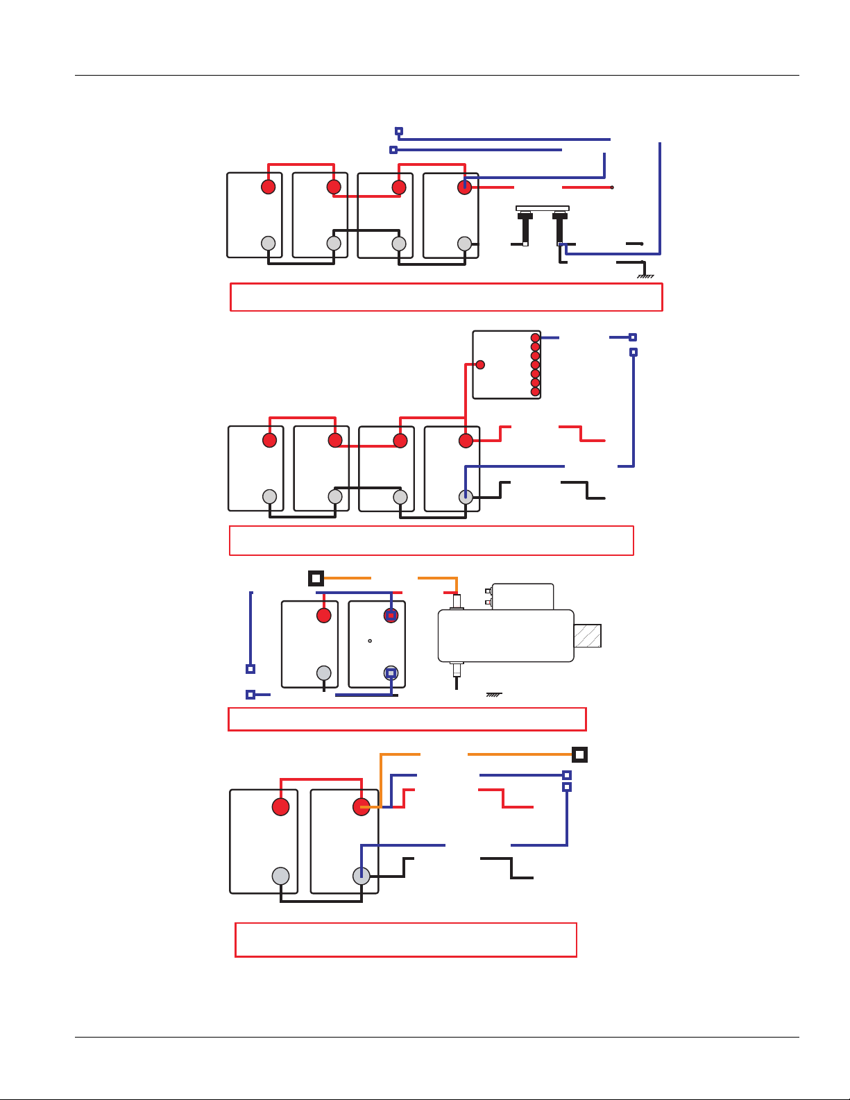
RETRATSTTAB ERYP LUS 2
RETRATSETTABRY M INUS 2
RETRATSETTABRY M INUS 1
RETRATS TTAB ERY P LUS 1
+-
BATTERY
12 VOLT
+-
BATTERY
12 VOLT
+-
BATTERY
12 VOLT
+-
BATTERY
12 VOLT
RATS OT SREPMUJ LAUD - KNAB REP SEIRETTAB OWT - SKNAB YRETTAB OWT TER
REWOP 3 NEG .SRIAP YB LELLARAP NI DETCENNOC ERA SEIRETTAB SUPPLI
ED BY
A SULP HTOB( RETRATS OT TSESOLC YRETTAB ND MINUS)
RETRATS ETTABRYM INUS 1
RETRATSTTABERYP LUS 1
+-
BATTERY
12 VOLT
+-
BATTERY
12 VOLT
+-
BATTERY
12 VOLT
+-
BATTERY
12 VOLT
AMG
LERAY
ENNOCSID HTIW KNAB REP SEIRETTAB OWT - SKNAB YRETTAB OWT CT
EV DNA BAC ROF TCENNOCSID - SRIAP YB LELLARAP NI DETCENNOC ERA SEIRETTAB HIC
LE START -
PAC TNEMNIATRETNE DNA TROFMOC BAC "EGRAHCSID PEED" SEDIVORP RIAP DETCENNOCSID ABIL
ITY.
C DNA RETRATS OT TSESOLC TES YRETTAB MORF DEILPPUS REWOP 3 NEG OMMONTO CAB POWER
ETTAB UCE 3 NEGRY MINUS
TAB UCE 3 NEGTERYPLUS
ETTAB UCE 3 NEGRYMINUS
RETRATSETTAB RY M INUS 1
RETRATSTTABERYP LUS 1
+-
BATTERY
12 VOLT
+-
BATTERY
12 VOLT
+-
BATTERY
12 VOLT
+-
BATTERY
12 VOLT
IRETTAB RUOF - KNAB YRETTAB ENOES
REWOP 3 NEG .LELLARAP NI DETCENNOC ERA SEIRETTAB SUPPLIED FROM
HTOB( .REWOP BAC HTIW RETRATS OT TSESOLC YRETTABP
LUS AND MINUS)
TAB UCE 3 NEGTERYPLUS
ETTAB UCE 3 NEGRYMINUS
TTAB BACERYPLUS
TAB UCE 3 NEGTERYPLUS
TTAB BAC ERY PLUS
Preferred +12 Volt Connections
TRTS0930
14
© 2016 Eaton. All rights reserved
2016.01.15
Page 20
TRTS0930
Preferred +12 Volt Connections
Electrical Pretest Procedures | Electrical Pretest
NUS
AB UCE 3 NEG RY MI
B UCE 3 NEG TERYPLUS
TA
ETT
+-
12 VOLT
BATTERY
12 VOLT
BATTERY
+-
12 VOLT
BATTERY
GEN 3 ECU BATTERY PLUS
12 VOLT
BATTERY
NOITUBIRTSID REWOP MODULE
+-
12 VOLT
BATTERY
+-
+-
+-
12 VOLT
BATTERY
+-
12 VOLT
BATTERY
CAB BATTERY PLUS
Starter Battery Plus
+-
12 VOLT
BATTERY
+-
12 VOLT
BATTERY
TIWS TCENNOCSID EVITAGEN YRETTAB - SKNAB YRETTAB OWTCH
DEVICES)
+-
12 VOLT
BATTERY
OLTAGEDROP
WOL ROF DEZIMITPO HTGNEL DNA EZIS SELBAC .RETRATSV
YRETTAB M INUS
OVER CURRENT
(POWER BUS AND
MODULE
AB RETRATSTTERY PLUS
DISTRIBUTION
POWER
AB RETRATSTTERYPLUS
TAB RETRATS TERY MINUS
TTAB NO DETCENNOC SUNIM DNA SULP REWOP ,LELLARAP NI DETCENNOC ERA SEIRETTAB ERY CLO OT TSES EHT
EWOP 3 NEG .EDISNI DEROTS ELCIHEV NEHW NWOD REWOP TA DETCENNOCSID ERA SEIRETTAB RSUPPL
D OT NOITCENNOC ELBAC ELCIHEV FO TNIOP TA NOITCENNOC EVITAGEN .RETRATS EHT OT TSESOLC IS
TAB RETRATS TERYMINUS
TTAB ELCIHEVERY MINUS
IED FROMBATTERY
CONNECT SW ITCH
TAB UCE 3 NEGTERYPLUS
ETTAB UCE 3 NEGRYMINUS
STARTER
2016.01.15
GEN 3 ECU BATTERY MINUS
STARTER BATTERY CONNECTION
GEN 3 POWER PLUS AND MINUS CONNECTED ON BATTERY CLOSEST TO THE STARTER.
+-
12 VOLT
BATTERY
ONE BATTERY BANK - TWO BATTERIES
BATTERIES ARE CONNECTED IN PARALLEL. GEN 3 POWER SUPPLIED FROM
BATTERY CLOSEST TO STARTER WITH CAB POWER. (BOTH PLUS AND MINUS)
+-
12 VOLT
BATTERY
STARTER BATTERY MINUS
CAB BATTERY PLUS
GEN 3 ECU BATTERY PLUS
STARTER BATTERY PLUS 1
GEN 3 ECU BATTERY MINUS
STARTER BATTERY MINUS 1
© 2016 Eaton. All rights reserved
15
Page 21
Electrical Pretest | Electrical Pretest Procedures
STARTER BATTERY PLUS
2
STARTER BATTERY MINUS
2
STARTER BATTERY MINUS
1
+ -
BATTERY
12 VOLT
+ -
BATTERY
12 VOLT
+ -
BATTERY
12 VOLT
+ -
BATTERY
12 VOLT
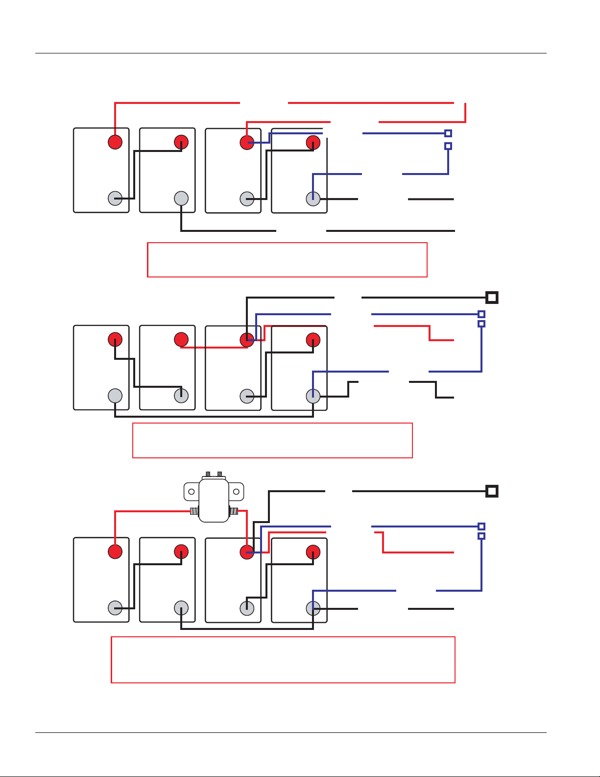
TWO BATTERY BANKS - TWO BATTERIES IN SERIES PER BANK - DUAL JUMPERS TO
STARTER
BATTERIES ARE CONNECTED IN SERIES/PARALLEL BY PAIRS. GEN 3 POWER
SUPPLIED BY BATTERY CLOSEST TO STARTER (BOTH PLUS AND MINUS)
+ -
BATTERY
12 VOLT
+ -
BATTERY
12 VOLT
+ -
BATTERY
12 VOLT
+ -
BATTERY
12 VOLT
MAG
RELAY
TWO BATTERY BANKS - TWO BATTERIES PER BANK WITH DISCONNECT
BATTERIES ARE CONNECTED IN SERIES/PARALLEL BY PAIRS - DISCONNECT FOR CAB AND VEHICLE
START - DISCONNECTED PAIR PROVIDES "DEEP DISCHARGE" CAB COMFORT AND ENTERTAINMENT
CAPABILITY. GEN 3 POWER SUPPLIED FROM BATTERY SET CLOSEST TO STARTER AND COMMON TO
CAB POWER
GEN 3 ECU BATTERY
PLUS
GEN 3 ECU BATTERY
MINUS
STARTER BATTERY MINUS
1
STARTER BATTERY PLUS
1
+ -
BATTERY
12 VOLT
+ -
BATTERY
12 VOLT
+ -
BATTERY
12 VOLT
+ -
BATTERY
12 VOLT
ONE BATTERY BANK - FOUR BATTERIES - ONE CABLE PAIR TO STARTER
BATTERIES ARE CONNECTED IN SERIES/PARALLEL BY PAIRS. GEN 3 POWER
SUPPLIED FROM BATTERY CLOSEST TO STARTER WITH CAB POWER. (BOTH PLUS
AND MINUS)
GEN 3 ECU BATTERY
PLUS
GEN 3 ECU BATTERY
MINUS
CAB BATTERY
PLUS
STARTER BATTERY PLUS
1
STARTER BATTERY MINUS
1
STARTER BATTERY PLUS
1
GEN 3 ECU BATTERY
MINUS
CAB BATTERY
PLUS
GEN 3 ECU BATTERY
PLUS
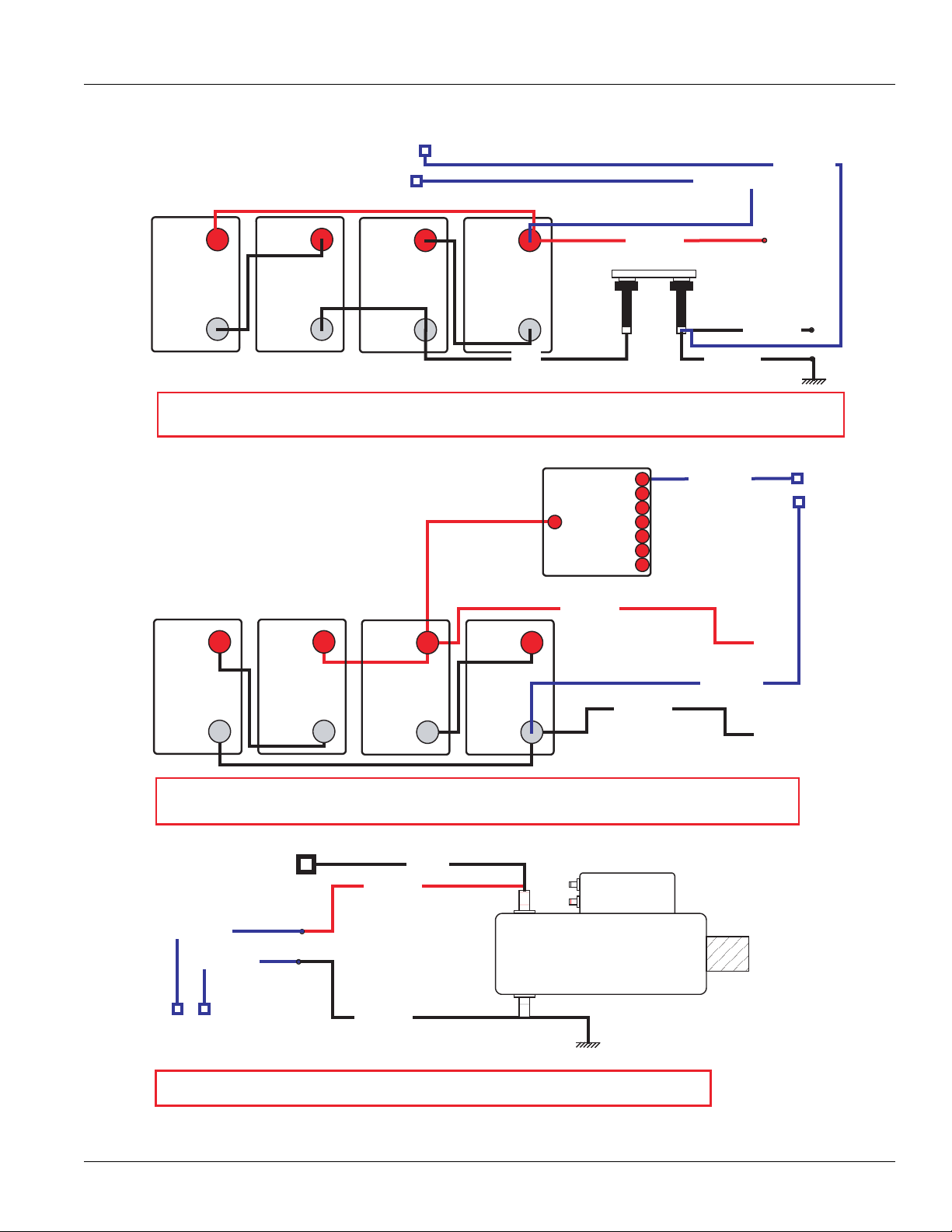
Preferred +24 Volt Connections
TRTS0930
16
© 2016 Eaton. All rights reserved
2016.01.15
Page 22
TRTS0930
+-
BATTERY
12 VOLT
+-
BATTERY
12 VOLT
+-
BATTERY
12 VOLT
+-
BATTERY
12 VOLT
TWO BATTERY BANKS - BATTERY NEGATIVE DISCONNECT SWITCH
BATTERIES ARE DISCONNECTED AT POWER DOWN WHEN VEHICLE STORED INSIDE. GEN 3 POWER SUPPLIED FROM BATTERY
CLOSEST TO THE STARTER. NEGATIVE CONNECTION AT POINT OF VEHICLE CABLE CONNECTION TO DISCONNECT SWITCH
BATTERY
MINUS
STARTER BATTERY
PLUS
STARTER BATTERY
MINUS
VEHICLE BATTERY
MINUS
GEN 3 ECU BATTERY
PLUS
GEN 3 ECU BATTERY
MINUS
STARTER BATTERY
MINUS
STARTER BATTERY
PLUS
+-
BATTERY
12 VOLT
+-
BATTERY
12 VOLT
+-
BATTERY
12 VOLT
+-
BATTERY
12 VOLT
POWER DISTRIBUTION MODULE
BATTERIES ARE CONNECTED IN SERIES/PARALLEL, POWER PLUS AND MINUS CONNECTED ON BATTERY CLOSEST TO THE
STARTER. CABLES SIZE AND LENGTH OPTIMIZED FOR LOW VOLTAGE DROP
GEN 3 ECU BATTERY
PLUS
GEN 3 ECU BATTERY
MINUS
POWER
DISTRIBUTION
MODULE
(POWER BUS AND
OVER CURRENT
DEVICES)
STARTER BATTERY
MINUS
STARTER BATTERY
PLUS
STARTER
CAB BATTERY
PLUS
GEN 3 ECU BATTERY
MINUS
GEN 3 ECU BATTERY
PLUS
STARTER BATTERY CONNECTION
GEN 3 POWER PLUS AND MINUS CONNECTED ON BATTERY CLOSEST TO THE STARTER.
Preferred +24 Volt Connections
Electrical Pretest Procedures | Electrical Pretest
© 2016 Eaton. All rights reserved
2016.01.15
17
Page 23

Electrical Pretest | Electrical Pretest Procedures
TECU Ignition Circuit
TRTS0930
1.
4.
37
13 14
35
1. TECU connector (vehicle interface)
2. 10 AMP only, manual resetting circuit
P fuse
10 AM
3. Ignition Key Switch
J1
35
29 30
23
15 16
7389
1 2
31
24 25
17
breaker OR
2.
32 33
26
27 28
18 19
10611 12
4 5
3.
34
20
38
21
22
36
Note: Run to main power lead that feeds the ignition
bus (OEM responsible for overcurrent protection
on this line)
4. TECU Connector (vehicle interface) front view
From To
J1-35 VIGN
Battery and ignition power and ground to the TECU must
not be switched off during the engine start process.
18
© 2016 Eaton. All rights reserved
2016.01.15
Page 24

TRTS0930
+ Battery
10
11
C
D
B
F
G
A
A
F
J
E
G
H
D
C
B
J1
J1939 Low
J1939 High
1.
2.
3.
J1939 Data Link
Electrical Pretest Procedures | Electrical Pretest
1. TECU connector (vehicle interface)
2. J1587 Data Link
3. 9-Way, for transmission diagnostics
J1939 Troubleshooting
1. Check the resistance of the J1939 Data Link.
2. Key off. Measure resistance between the
diagnostic connector
the read
ing. The reading should be 60 ohms of
resistance (between 50 and 70.)
3. Check resistance between Pin C and Pin A and
resistance
readi
between Pin D and Pin A.
ngs should be 10K ohms or greater (open cir-
cuit).
Note: Pin C
= J1939+, Pin D = J1939-, Pin A is a chas-
sis ground
• If an Inactive data link fa
by the TE
on pag
CU, See “Product Diagnostic (PD) Mode
e 11. PDM should be utilized before any fur-
ther steps are taken.
Pin C and Pin D and
ult code is being reported
9-way
record
These two
the
”
2016.01.15
© 2016 Eaton. All rights reserved
19
Page 25

Electrical Pretest | Electrical Pretest Procedures
+
–
+
–
Batteries
30 AMP fuse
Transmission ECU
4-Pin Diagnostic Port
(Located at the left rear
corner of the transmission.)
4-Pin Diagnostics Port
4-way
B - Service Bat. +
C - Service Bat. A - Service Ignition +
VOLTS
V
COM
A
Battery Negative Post
B
A
D
C
Warning! - Do Not Load Test at Diagnostic Port
Electrical Pretest
TRTS0930
Purpose: Measure battery voltage. Visually inspect
the batteries, inline fuse and power and ground
A
supplies at the batteries.
1. Key off.
2. Remove and clean all battery and batter
conn
ections.
y-to-frame
3. Remove and clean ground supply to engine ECU.
4. Inspect starter/battery and inline 30 amp
er connections for corrosion or damaged con-
hold
fuse
tacts.
5. Measure voltage across
batteries.
• If voltage is 11 to 13 volts on a 12- volt system
22 to 26 on a 24 volt system, refer
or
to OEM
guidelines for battery load test. Repair or
repla
ce batteries as required. Go to Step
B.
Purpose: Verify proper ground path between the
batteries and the transmission harness 4-way diag-
B
nostic connector.
1. Locate diagnostic port on Transmission Harness.
2. Key on.
3. Measure voltage between Pin C and the batter
tive post.
nega
• If voltage is 0.70 volts or less, go to Step
y
C.
20
• If voltage is outside of range, repair or replace
batteries and charging system
as required.
Repeat this step.
© 2016 Eaton. All rights reserved
• If voltage is outside of range, repair battery
ground supply to Transmission Electrical Control Unit (TECU). Repeat test.
2016.01.15
Page 26

TRTS0930
4-Pin Diagnostics Port
4-way
B - Service Bat. +
C - Service Bat. A - Service Ignition +
B
A
D
C
4-Pin Diagnostic Port
(Located at the left rear
corner of the transmission.)
Warning! - Do Not Load Test at Diagnostic Port
Electrical Pretest Procedures | Electrical Pretest
Purpose: Measure proper battery voltage at the
C
transmission harness 4-way diagnostic connector.
1. Locate diagnostic port on Transmission Harness.
2. Key on.
3. Measure voltage between Pin B and Pin C.
• If voltage is within 0.6 volts of battery
Step
go to
D.
voltage,
Purpose: Measure proper ignition voltage at the
D
transmission harness 4-way diagnostic connector.
1. Key on.
Warning: Do not load test at the diagnostic port.
2. Measure voltage between Pin A and Pin C.
Warning! - Do Not Load Test at Diagnostic Port
4-Pin Diagnostics Port
B
A
D
C
4-way
4-Pin Diagnostic Port
(Located at the left rear
corner of the transmission.)
B - Service Bat. +
C - Service Bat. A - Service Ignition +
• If voltage is within 0.6 volts of battery
test complete.
voltage,
• If voltage is outside of range, Repair battery
power supply to TECU. Fuse may be bl
own.
Repeat test.
• If
voltage is outside of range, repair ignition
power supply to TECU. Fuse may be blown.
Repeat test.
2016.01.15
© 2016 Eaton. All rights reserved
21
Page 27

Power-Up Sequence Test | Electrical Pretest Procedures
Power-Up Sequence Test
Overview
This test does not relate to any specific fault code, but must
be completed if the self check fails at power-up.
Detection
The TECU checks the program memory every time the key
is turned on.
Fallback
This causes an In-Place fallback while moving and a
self-check failure if it occurs during power-up.
Possible Causes
This fault code can be caused by any of the following:
• Vehicle Harness
• Shift Control Device
• TECU
TRTS0930
22
© 2016 Eaton. All rights reserved
2016.01.15
Page 28

TRTS0930
4.
VOLUME
CONTROL
SERVICE
SHIFT
Eaton Fuller
Transmissions
L
H
D
N
R
1.
2.
3.
Component Identification
Electrical Pretest Procedures | Power-Up Sequence Test
1. Side view of pushbutton shift control
2. Transmission controller 30-way connector
3. Top view of pushbutton shift control
4. Eaton Cobra Lever
2016.01.15
© 2016 Eaton. All rights reserved
23
Page 29

Power-Up Sequence Test | Electrical Pretest Procedures
Power-Up Sequence Test
TRTS0930
Purpose: Measure battery voltage. Visually inspect
the batteries, inline fuse and power and ground
A
supplies at the batteries.
1. Key off.
2. Remove and clean all battery and batter
conn
ections.
3. Remove and clean ground supply to engine ECU.
4. Inspect starter/battery and
er connections for corrosion or damaged con-
hold
tacts.
5. Measure voltage across
voltage is 11 to 13 volts on a 12-volt
• If
or 22 to
battery load test. Repair or replace batteries as
req
• If voltage is outside of range, repair or replace
batteries and charging system
Repeat this step.
26 on a 24-vo
uired. Go to Step
inline 30-amp fuse
batteries.
lt system, proceed with
B.
y-to- frame
system
as required.
Purpose: Measure proper battery voltage at the
C
transmission harness 4-way diagnostic connector.
1. Locate diagnostic port on Transmission Harness.
2. Key on.
3. Measure voltage between Pin B and Pin C.
Warning: Do not load test at the diagnostic port.
!
• If voltage is within 0.6 volts of battery
to Step
go
• If voltage is outside of range, repair battery
power supply to TECU. Fuse may be blown.
Repeat test.
Purpose: Measure proper ignition voltage at the
D
transmission harness 4-way diagnostic connector.
D.
voltage,
Purpose: Verify proper ground path between the
batteries and the transmission harness 4-way diag-
B
nostic connector.
1. Locate diagnostic port on Transmission Harness.
2. Key on.
3. Measure voltage between Pin C and the batter
ive post.
negat
• If voltage is 0.70 volts or less, go to Step
• If voltage is outside of range, repair battery
ground
supply to TECU. Repeat test.
1. Key on.
2. Measure voltage between Pin A and Pin C.
• If voltage is within 0.6 volts of battery
to Step
go
• If voltage is outside of range, repair Ignition
power supply to ECU. Fuse may be bl
Repeat test.
y
C.
E.
voltage,
own.
24
© 2016 Eaton. All rights reserved
2016.01.15
Page 30

TRTS0930
Electrical Pretest Procedures | Power-Up Sequence Test
Purpose: Visually identify if the vehicle is equipped
E
with a shift lever or push button.
1. Is vehicle equipped with an Shift Lever?
• If vehicle is not equipped with a Shift Lever,
to Step
F.
• If vehicle is equipped with a Shift Lever, go to
St
K.
ep
Purpose: Visually identify if the push button is an
Eaton built push button or an OEM built J1939
F
push button.
1. Is it an Eaton Push Button or OEM J1939 Shift
Devic
e?
• If an Eaton Push Button Shift Control, go to
G.
Step
• If an OEM J1939 Shift Device, refer to OEM for
troubleshooting procedures.
go
Purpose: Visually observe the Service light during
G
key-on power up.
1. Key on.
2. Observe Service light.
Note: If Service light is flashing, go to
Procedure.
• If Ser
• If Service light never lights, go to Step
• If Service light is on steady, replace Shift Con-
Purpose: Measure the voltage supply at the Shift
H
Control device.
1. Key off.
2. Disconnect Shift Control 30-way connector.
vice light illuminates for 1 second
turns off, test complete.
trol. Go to Step V.
Diagnostics
and
H.
3. Key on.
4. Measure voltage between Pin C1 and
Control 30-way.
Shift
• If voltage is within 1 volt of battery
replace S
• If voltage is outside of range, go to Step I.
hift Control
. Go to Step V.
Pin J3 on the
voltage
2016.01.15
© 2016 Eaton. All rights reserved
25
Page 31

Power-Up Sequence Test | Electrical Pretest Procedures
TRTS0930
Purpose: Verify that a proper ground path is being
supplied to the Shift Control Device through the Ve-
I
hicle Harness and test for a short to ground.
1. Key off.
2. Disconnect negative battery cable.
3. Disconnect 38-way Vehicle Harness from TECU.
4. Measure resistance between TECU Pin
ntrol connector Pin J3 and from then from
Co
J3 to groun
• If resistance from Pin
• If resistance is outside of range, repair the
d.
25 to J3 is
0 to 0.3 ohms and resistance from J3 to
is OL / Open, go to Step
ground
V
ehicle Harness. Go to Step
25 and Shift
J.
V.
Pin
Purpose: Visually identify if the shift lever is an Ea-
K
ton built shift lever or an OEM built shift lever.
1. Is vehicle equipped with an Eaton supplied Shift
Lever
or an OEM supplied Shift Lever.
• If Eaton Cobra Lever, go to Step
• If OEM Shift Lever, go to Step R.
Purpose: Visually observe the Service light during
L
key-on power up.
1. Key on.
2. Observe Service light.
Note: If Service light is flashing, See “Diagnosti
Proced
ures” on page 3.
L.
c
Purpose: Measure the resistance of the ignition
voltage supply wire to the Shift Control Device
J
through the Vehicle Harness and test for a short to
ground.
1. Measure resistance between TECU Pin 31 and Shift
Co
ntrol connector Pin C1 and then from Pin C1 to
ground.
• If resistance from Pin 31 to C1 is 0 to
ohm
s and resistance from C1 to ground is 10
OL, replace the TECU. Go to Step
or
• If resistance is outside of range, repair the
V
ehicle Harness. Go to Step
V.
0.3
V.
• If Service light illuminates for 1 second
turns off, test complete.
• If Service light never comes on, go to Step
• If Service light is on steady, go to Step M.
K
and
O.
26
© 2016 Eaton. All rights reserved
2016.01.15
Page 32

TRTS0930
Electrical Pretest Procedures | Power-Up Sequence Test
Purpose: Measure the voltage supply to the Service
M
light during key-on power up.
1. Disconnect Shift Lever 8-way connector.
2. Key on.
3. Measure voltage at Pin 6 and ground.
• If voltage is within 2 volts of battery voltage
one second, then 0 v
bra Lever
Co
• If voltage is constant, go to Step N.
Purpose: - Test the Service light voltage supply for
N
short to power through the Vehicle Harness.
1. Key off.
2. Disconnect negative cable.
3. Disconnect 38-way Vehicle Harness connector.
4. Measure resistance between Pin 6 and Pin 4.
• If resistance is OL, replace the:
- Medium-Duty Transmission Electronic Control Unit (TECU)
- Heavy-Duty Transmission Electronic Control Unit (TECU)
Go to Step V.
• If resistance is less than 10K, repair the Vehi-
cle Harness and go to Step
. Go to Step V.
olts,
replace the Eaton
V.
for
Purpose: Measure the voltage supply to the Service
O
light during key-on power up.
1. Key off.
2. Disconnect Shift Lever 8-way connector.
3. Key on.
4. Measure voltage between Pin 3 and Pin
• If within
Lever, go to Step V.
• If voltage is outside of range, go to Step N.
Purpose: Verify that a proper ground path is being
supplied to the Shift Lever through the Vehicle Har-
P
ness and test for a short to ground.
1. Key off
2. Disconnect 38-way Vehicle Harness connector on
TECU.
3. Measure resistance between Pin 3
connector and Pin 25 on the 38-way connector and
from
Pin 25 to ground.
Note: On Peterbilt disconnect Gear Display,
• If resistance between Pin 3 and Pin 25 is 0
0.3 ohm
ground is OL, go to Step
• If resistance is outside of range, repair the
V
38-way connector
8-way
1 volt of battery replace Eaton
s and resistance from Pin 25 to
Q.
ehicle Harness between the Vehicle
Pin 25 and Ve
connector Pin 3. Go to Step
6.
Cobra
on the 8-way
Harness
hicle Harness
V.
to
2016.01.15
© 2016 Eaton. All rights reserved
27
Page 33

Power-Up Sequence Test | Electrical Pretest Procedures
TRTS0930
Purpose: Measure the resistance of the ignition
voltage supply to the Shift Lever through the Vehi-
Q
cle Harness and test for a short to ground.
1. Key off.
2. Measure resistance
- V
ehicle Harness 38-way connector Pin
V
ehicle Harness 8-way connector Pin 4
- Vehicle Harness 38-way connector Pin
ground
• If resist
0.3 ohms
ground
is OL, replace the:
- Medium-Duty Transmission Electronic Control Unit (TECU)
- Heavy-Duty Transmission Electronic Control Unit (TECU)
Go to Step V.
• If any of the above conditions are not met,
repla
ce the Vehicle Harness between Ve
Harness 38-way connector Pin 31 and Vehicle
Harness 8-way
between:
ance between Pin 31 and Pin 4 is 0 to
and if resistance between Pin 31 and
connector Pin 4. Go to Step
31 and
31 and
hicle
V.
Purpose: Measure the voltage supply to the Service
R
light during key-on power up.
1. Key off.
2. Locate Service light connector on Vehicle Harness.
3. Key on.
4. Measure voltage across Pin A and Pin B on the Ser-
vice light connector
• If voltage is within 2 volts of battery voltage
1 second, then
• If no voltage is measured, go to Step
• If voltage is within 2 volts of battery voltage
con
tinuously, go to Step
0 volts, test complete.
S.
T.
for
28
© 2016 Eaton. All rights reserved
2016.01.15
Page 34

TRTS0930
Electrical Pretest Procedures | Power-Up Sequence Test
Purpose: Measure the resistance of the service
light supply wire to the Shift Lever through the Ve-
S
hicle Harness and test for a short to ground.
1. Key off.
2. Disconnect negative battery cable.
3. Disconnect 38-way connector.
4. Measure resistance from Pin A of the OEM connec-
tor to Pin 23 of the 38-way and from Pin 23 to
ground.
• If resistance from Pin A to Pin 23 is 0 to 0.
s and resistance to gro
ohm
greater, replace the:
-
Medium-Duty Transmission Electronic Control Unit (TECU)
- Heavy-Duty Transmission Electronic Control Unit (TECU)
Go to Step V.
• If resistance is outside of range, repair the
V
ehicle Harness and go to Step
und is 10K or
V.
Purpose: Test for a short to power at the Shift Le-
T
ver Service light.
1. Key off.
2. Disconnect negative battery cable.
3. Disconnect TECU 38-way connector.
4. Measure voltage across Service light
A and Pin
• If no voltage is measured, replace the:
3
• If voltage is within 2 volts of battery voltage,
B.
- Medium-Duty Transmission Electronic Control Unit (TECU)
- Heavy-Duty Transmission Electronic Control Unit (TECU)
Go to Step V.
repair V
V.
ehicle Harness as required. Go to St
connector Pin
ep
Purpose: Verify that the system will properly power
V
up.
1. Key off.
2. Reconnect all connectors and the negative batter
cable.
3. Key on.
• If
Power-Up Sequence Test completes, te
complete.
Power-Up Sequence Test fails go to Step
• If
fin
d error in testing.
y
st
A.
2016.01.15
© 2016 Eaton. All rights reserved
29
Page 35

Fault Code 11 - No TECU Operation | Fault Isolation Procedures
Fault Code 11 - No TECU Operation
J1939: SA 3 SPN 629 FMI 12
J1587: MID130 PID FMI 12
Overview
This fault code indicates an internal failure of the Transmission Electronic Control Unit (TECU).
Detection
The TECU checks the program memory every time the key
is turned on and throughout operation. If the TECU is able
to detect a failure within its own memory, it sets this fault
code.
Fallback
This fault causes a vehicle In Place fallback while moving
and a self-check failure if it occurs during power-up.
Possible Causes
This fault code can be caused by the following:
TRTS0930
• TECU
30
© 2016 Eaton. All rights reserved
2016.01.15
Page 36

TRTS0930
1.
Component Identification
Fault Isolation Procedures | Fault Code 11 - No TECU Operation
1. TECU
2016.01.15
© 2016 Eaton. All rights reserved
31
Page 37

Fault Code 11 - No TECU Operation | Fault Isolation Procedures
Fault Code 11 - No TECU Operation
Purpose: Check for active or Inactive fault codes
A
1. Key on.
2. Retrieve codes. See “Fault Code Retrieval/Clearing”
on page
5.
TRTS0930
• If Fault
-
- Heavy-Duty Transmission Electronic Con-
• If Fault Code 11 is Inactive, test complete.
Code 11 is Active, replace
Medium-Duty Transmission Electronic Control Unit (TECU)
trol Unit (TECU)
the:
32
© 2016 Eaton. All rights reserved
2016.01.15
Page 38

TRTS0930
Fault Isolation Procedures | Fault Code 11 - No TECU Operation
2016.01.15
© 2016 Eaton. All rights reserved
33
Page 39

Fault Code 12 - Improper ECU Configuration | Fault Isolation Procedures
Fault Code 12 - Improper ECU Configuration
J1939: SA 3 SPN 629 FMI 13,14
Overview
This fault code indicates the Transmission Electronic Control Unit (TECU) is not reading valid information from memory, including the transmission table and calibration values.
Detection
The TECU checks the configuration every time the key is
turned on. If the transmission is not able to detect the
proper configuration, it sets this fault code.
Fallback
This fault causes a power up no crank.
Possible Causes
This fault code can be caused by the following:
• Improper TECU configuration software
TRTS0930
34
© 2016 Eaton. All rights reserved
2016.01.15
Page 40

TRTS0930
1.
Component Identification
Fault Isolation Procedures | Fault Code 12 - Improper ECU Configuration
1. TECU
2016.01.15
© 2016 Eaton. All rights reserved
35
Page 41

Fault Code 12 - Improper ECU Configuration | Fault Isolation Procedures
Fault Code 12 - Improper ECU Configuration
Purpose: Check for active or Inactive fault codes.
A
1. Key on.
2. Retrieve codes. See “Fault Code Retrieval/Clearing”
on page 5.
TRTS0930
• If Fault Code 12 is Active, Customer -
Eato
n at 1-800-826-HELP (43
T
echnician Service.
• If Fault Code 12
is Inactive, test complete.
57). CSC - Call
Call
36
© 2016 Eaton. All rights reserved
2016.01.15
Page 42

TRTS0930
Fault Isolation Procedures | Fault Code 12 - Improper ECU Configuration
2016.01.15
© 2016 Eaton. All rights reserved
37
Page 43

Fault Code 13 - J1939 Shift Control Device | Fault Isolation Procedures
Fault Code 13 - J1939 Shift Control Device
J1587: MID130 PID 231 FMI 8, 11
J1939: SA 3 SPN751 FMI 8, 11
Overview
This fault indicates communication has been lost, or does
not correspond with the neutral request input from the
J1939 Shift Device.
When troubleshooting an Inactive code, See “Product Diagnostic (PD) Mode” on page 11.
Detection
Starting at key on and throughout operation, the Transmission Electronic Control Unit (TECU) constantly monitors
communication with the J1939 Shift Device. If a neutral
request from the J1939 Shift Device does not match the
neutral signal or is not received from the J1939 Shift
Device, Fault Code 13 is set.
TRTS0930
Fallback
This fault causes a downshift-only fallback. Once the transmission re-engages the start gear, there will be no upshifts
as long as the code is active.
Possible Causes
This fault code can be caused by the following:
• OEM J1939 Shift Control Device
• Vehicle Harness
38
© 2016 Eaton. All rights reserved
2016.01.15
Page 44

TRTS0930
J1
J1939
16
17
1.
2.
3.
4.
5.
Component Identification
Fault Isolation Procedures | Fault Code 13 - J1939 Shift Control Device
1. TECU Connector (vehicle interface)
2. Bulkhead connector located at firewall
3. OEM J1939 Shift Device
4. Battery Power (Non-switches power run to battery
or starter)
5. Switched Power
2016.01.15
© 2016 Eaton. All rights reserved
39
Page 45

Fault Code 13 - J1939 Shift Control Device | Fault Isolation Procedures
OHMS
V
COM
A
OHMS
V
COM
A
31
24 25
29 30
15 16
26
20
34
27 28
32 33
18 19
7389
12 6
11 12
45
22
21
38
36
37
13 14
35
10
17
23
31
24 25
29 30
15 16
26
20
34
27 28
32 33
18 19
7389
12 6
11 12
45
22
21
38
36
37
13 14
35
10
17
23
J1939
Fault Code 13 - J1939 Shift Control Device
TRTS0930
Purpose: Verify continuity of Neutral Request Sig-
A
nal wire
1. Key off.
2. Disconnect negative battery cable.
3. Disconnect Vehicle Harness 38-way connector.
4. Measure resistance between 38-way
corresponding OEM pin at J19
16 and
ce and Pin 16 and ground (see
Devi
connector Pin
39 Shift
OEM wiring for
correct pin location)
37
13 14
35
37
13 14
35
• If resist
29 30
31
24 25
23
17
15 16
7389
12 6
29 30
31
24 25
23
17
15 16
7389
12 6
ance is 0 to 0.3 ohms between Pin 16
32 33
26
27 28
18 19
11 12
10
45
32 33
26
27 28
18 19
11 12
10
45
34
38
22
21
20
36
34
38
21
20
22
36
and the corresponding OEM pin and resistance
to groun
d is 10K ohms or greater, go to St
B.
• If resistance is out of range, replace the:
- Medium-Duty Transmission Harness
- Heavy-Duty Transmission Harness
Go to Step V.
OHMS
V
COM
J1939
OHMS
V
COM
A
A
ep
Purpose: Verify continuity of Neutral Request Re-
B
turn wire
1. Measure resistance between 38-way connector Pin
17
and corresponding OEM pin at J1939 Shift
Device and Pin 17 and ground (see OEM wiring fo
correct pin
• If resistance
loca
tion).
is 0 to 0.3 ohms between Pin 17
and the corresponding OEM pin and resistance
ground is 10K ohms or greater, problem
to
exists with the J1939 Shift Device, or J1939
Shift Device power, ground or data link wiring
Cont
act your OEM for repair strategy. Go to
V.
Step
• If resistance is out of range, replace the:
- Medium-Duty Transmission Harness
- Heavy-Duty Transmission Harness
Go to Step V.
r
.
40
© 2016 Eaton. All rights reserved
2016.01.15
Page 46

TRTS0930
V
1. Key off.
Fault Isolation Procedures | Fault Code 13 - J1939 Shift Control Device
Purpose: Verify repair.
2. Reconnect all connectors and the negative batter
cable.
3. Key on.
4. Clear codes. See “Fault Code Retrieval/
page 5.
5. Drive vehicle
6. Check for codes. See “Fault Code Retrieval/Clear-
ing” on page 5.
• If no fault codes, test complete.
• If Fault Code 13 appears go to Step
error in testing.
• If fault code other than 13
Co
and attempt to reset the code.
de Isolation Procedure Index” on page 8.
Clearing” on
A. to find
appears, See “Fault
y
2016.01.15
© 2016 Eaton. All rights reserved
41
Page 47

Fault Code 14 - Invalid Shift Lever Voltage (without Park Pawl) | Fault Isolation Procedures
Fault Code 14 - Invalid Shift Lever Voltage (without Park Pawl)
J1587: MID 130 SID 18, 19 FMI 2, 3, 4, 5
J1939: SA 3 SPN 751 FMI 2, 3, 4, 5
Overview
This fault code indicates an electrical failure of the Eaton
Cobra Lever or OEM Shift Lever.
When troubleshooting an Inactive code See “Product Diagnostic (PD) Mode” on page 11.
Detection
Starting at key on and throughout operation the Transmission Electronic Control Unit (TECU) constantly monitors the
signal from the Park Pawl Position Sensor. The transmission monitors both sensor signals, if one signal to the TECU
is out of range the code will set.
Fallback
This fault may cause a downshift only fallback mode. The
transmission will re-engage the start gear when returned to
a stop, but will not upshift as long as the code is active.
TRTS0930
Possible Causes
This fault code can be caused by any of the following:
• Eaton Cobra Lever or OEM Shift Lever
• Vehicle Harness
• TECU
42
© 2016 Eaton. All rights reserved
2016.01.15
Page 48

TRTS093
1.
2.
0 Fault Isolation Procedures | Fault Code 14 - Invalid Shift Lever Voltage (without Park Pawl)
Component Identification
1. Eaton Cobra Lever 8-way connector
2. TECU 38-way connector
2016.01.15
© 2016 Eaton. All rights reserved
43
Page 49

Fault Code 14 - Invalid Shift Lever Voltage (without Park Pawl) | Fault Isolation Procedures
OHMS
V
COM
A
OHMS
V
COM
A
31
24 25
29 30
15 16
26
20
34
27 28
32 33
18 19
7389
12 6
11 12
45
22
21
38
36
37
13 14
35
10
17
23
1
2
3
4
5
6
7
8
31
24 25
29 30
15 16
26
20
34
27 28
32 33
18 19
7389
12 6
11 12
45
22
21
38
36
37
13 14
35
10
17
23
Fault Code 14 - Invalid Shift Lever Voltage (without Park Pawl)
TRTS0930
Purpose: Visually identify the lever type: Eaton or
A
OEM manufactured.
1. Is vehicle equipped with an Eaton supplied Shift
Lever or a
• If Eaton Cobra Lever, go to Step
n OEM supplied Shift Lever?
B.
• If OEM Shift Lever, contact OEM for trouble-
shooting procedures.
Purpose: Install the Shift Lever tester and monitor
Transmission Range in ServiceRanger. Utilize the
B
Shift Lever Tester to verify transmission-lever interface.
1. Key off.
2. Disconnect Shift Lever 8-way connector.
Purpose: Verify continuity of auto mode input wire.
C
1. Key off.
2. Disconnect negative battery cable.
3. Disconnect TECU 38-way connector.
4. Remove tester from Shift Lever 8-way connector.
5. Measure resistance between:
- ECU 38-way Pin 15 and Shift Lever 8-way con-
nector Pin 1
- ECU 38-way connector Pin 15 and ground
3. Connect Shift Lever tester to the 8-way Shift Leve
r
harness.
4. Connect Ser
to diag
5. Key on.
6. Select Monitor Data.
7. Observe transmission range selected.
• If transmission range selected
repla
Active). Go to Step
viceRanger, a PC-based Service T
nostic port.
ce Cobra Lever
(only if fault code is
V.
ool,
equals neutral,
• If resistance between Pin 15 and Pin 1 is 0
0.3 ohms and resistance
d is 10K ohm or greater, go to Step
groun
between Pin
15 and
• If any of the above conditions are not met,
repair the OEM
Vehicle Harness between
TECU and the Eaton Cobra Lever
Go to Step
V.
.
the
to
D.
• If transmission range selected does not equal
neut
ral, go to Step
C.
44
© 2016 Eaton. All rights reserved
2016.01.15
Page 50

TRTS093
OHMS
V
COM
A
1
2
3
4
5
6
7
8
31
24 25
29 30
15 16
26
20
34
27 28
32 33
18 19
7389
12 6
11 12
45
22
21
38
36
37
13 14
35
10
17
23
OHMS
V
COM
A
31
24 25
29 30
15 16
26
20
34
27 28
32 33
18 19
7389
12 6
11 12
45
22
21
38
36
37
13 14
35
10
17
23
OHMS
V
COM
A
1
2
3
4
5
6
7
8
31
24 25
29 30
15 16
26
20
34
27 28
32 33
18 19
7389
12 6
11 12
45
22
21
38
36
37
13 14
35
10
17
23
OHMS
V
COM
A
31
24 25
29 30
15 16
26
20
34
27 28
32 33
18 19
7389
12 6
11 12
45
22
21
38
36
37
13 14
35
10
17
23
0 Fault Isolation Procedures | Fault Code 14 - Invalid Shift Lever Voltage (without Park Pawl)
Purpose: Verify continuity of manual mode input
D
wire.
1. Key off.
2. Measure resistance
- TECU
38-way Pin 16 and Shift Lever 8-way con-
between:
nector Pin 8
- TECU 38-way connector Pin 16 and ground
Purpose: Verify continuity of common ground
E
wire.
1. Key off.
2. Measure resistance
- TECU 38-way
8-way co
nnector Pin 2
between:
Pin 17 and Shift
- TECU 38-way connector Pin 17 and ground
Lever
• If resistance between Pin 16 and Pin 8 is 0 to
0.3 ohms and resistance between
is 10K ohm or greater, go to Step
ground
Pin 16 and
E.
• If any of the above conditions are not met,
repai
r the Vehicle Harness
Cobra
Lever and TECU. Go to Step
between the Eaton
V.
• If resistance between Pin 17 and Pin 2 is 0
0.3 ohms and resista
groun
d is 10K ohm or greater, go to Step
nce between Pin
• If any of the above conditions are not met,
repair the V
Cobra
ehicle Harness between the
Lever and TECU. Go to Step
V.
to
17 and
F.
Eaton
2016.01.15
© 2016 Eaton. All rights reserved
45
Page 51

Fault Code 14 - Invalid Shift Lever Voltage (without Park Pawl) | Fault Isolation Procedures
OHMS
V
COM
A
31
24 25
29 30
15 16
26
20
34
27 28
32 33
18 19
7389
12 6
11 12
45
22
21
38
36
37
13 14
35
10
17
23
OHMS
V
COM
A
31
24 25
29 30
15 16
26
20
34
27 28
32 33
18 19
7389
12 6
11 12
45
22
21
38
36
37
13 14
35
10
17
23
OHMS
V
COM
A
31
24 25
29 30
16
26
20
34
27 28
32 33
18 19
7389
12 6
11 12
45
22
21
38
36
37
13 14
35
10
15
23
17
TRTS0930
Purpose: Check for short circuits in the shift lever
F
wiring.
1. Key off.
2. Measure resistance
- Pin
15 and Pin 16 on the TECU 38-way connector.
between:
- Pin 15 and Pin 17 on the TECU 38-way connector.
- Pin 16 and Pin 17 on the TECU 38-way connector.
Purpose: Verify repair.
V
1. Key off.
2. Reconnect all connectors and the negative battery
cable.
3. Key on.
4. Clear codes, See “Fault Code Retrieval/Clearing”
e 5.
pag
5. Drive vehicle and attempt to reset the code.
6. Check for codes. See “Fault Code Retrieval/Clear-
ing” on page 5.
• If no codes, test complete.
• If code 14 appears, go to Step
in testin
g.
• If code other than 14 appears, See “Fault
Iso
lation Procedure Index” on page 8.
A. to find error
on
Code
46
• If resistance on all three is 10K ohm or greater
ce Shift Lever and go to Step
repla
• If any of the three readings is less than 10K
ohm,
repair the Vehicle Harness between
Eaton Cobra Lever
and TECU. Go to Step
,
V.
the
V.
© 2016 Eaton. All rights reserved
2016.01.15
Page 52

TRTS093
0 Fault Isolation Procedures | Fault Code 14 - Invalid Shift Lever Voltage (without Park Pawl)
2016.01.15
© 2016 Eaton. All rights reserved
47
Page 53

Fault Code 14 - Invalid Shift Lever Voltage (with Park Pawl) | Fault Isolation Procedures
Fault Code 14 - Invalid Shift Lever Voltage (with Park Pawl)
J1587: MID 130 SID 18, 19 FMI 2, 3, 4, 5
J1939: SA 3 SPN FMI 2, 3, 4, 5
Overview
This fault code indicates a possible failure of the Park Pawl
Position Sensor or OEM circuit. The sensor is a 4 wire dual
hall effect device. When troubleshooting an Inactive code
See “Product Diagnostic (PD) Mode” on page 11.
Detection
Starting at key on and throughout operation the Transmission Electronic Control Unit (TECU) constantly monitors the
signal from the Park Pawl Position Sensor. The transmission monitors both sensor signals, if one signal to the TECU
is out of range the code will set.
Fallback
This fault code will cause the transmission to be stuck in
the last known selected position. If the code comes active
while in gear, the transmission will a down shift only fallback mode. The transmission will re-engage the start gear
when returned to a stop, but will not upshift as long as the
code is Active.
TRTS0930
Possible Causes
This fault code can be caused by any of the following:
• Vehicle Harness
• Park Pawl Position Sensor
• TECU
48
© 2016 Eaton. All rights reserved
2016.01.15
Page 54

TRTS0930
28
31
24 25
29 30
15 16
26
20
34
27
32 33
18 19
7389
12 6
11 12
45
22
21
38
36
37
13 14
35
10
17
DEUTSCH
X
4
2
1
3
4
3
15
16
1
2
17
31
F2
1.
2.
3.
4.
Component Identification
Fault Isolation Procedures | Fault Code 14 - Invalid Shift Lever Voltage (with Park Pawl)
2016.01.15
1. Vehicle Harness 38-way Connector
2. 4-Pin Park Pawl Position Sensor Connector
(DTM06-4S)
3. Park Pawl Position Sensor
4. TECU Connector Front View (Vehicle Interface)
4-Way Pin# 38-Way PIN# Type
1 17 Ground
2 31 5 Volt Reference
3 16 Signal 1
4 15 Signal 2
© 2016 Eaton. All rights reserved
49
Page 55

Fault Code 14 - Invalid Shift Lever Voltage (will show “F” in display) | Fault Isolation Procedures
Fault Code 14 - Invalid Shift Lever Voltage (will show “F” in display)
TRTS0930
Purpose: Check for active or Inactive fault codes,
A
noting FMI.
1. Key on.
2. Retrieve active fault codes and FMIs with Ser-
viceRanger using the
9-way dia
• If Fault Code 14 FMI 2 is active, go to Step
• If Fault
• If Fault
Purpose: Perform Shift Cable Adjustment proce-
B
dure.
1. Key off.
2. Perform shift cable adjustment procedure per OEM
guidelines.
3. Key on.
4. Retrieve active fault codes and FMIs with Ser-
viceRanger using the 9-way diagnostic connector.
• If Fault Code 14 FMI 2 is Inactive, go to St
• If Fault
gnostic connector.
Code 14 FMI 3, 4 or 5 is
St
ep
D.
Code 14 is Inactive, See “Product Diag-
nostic (PD) Mode” on page 11.
V.
Code 14 FMI 2 is Active, go to Step
active, go to
ep
B.
C.
Purpose: Perform Park Pawl Position Sensor cali-
C
bration.
1. Perform Park Pawl Position Sensor calibration
2.
Key on.
3. Retri
D
1. Key off.
2. Disconnect the Park Pawl Position Sensor 4-
3. Key on.
4. At the Park Pawl Position Sensor 4-way connector
eve active fault codes and FMIs with Ser-
viceRanger using the 9-way diagnostic connector.
• If Fault Code 14 FMI 2 is Inactive, go to Step
V.
• If Fault Code 14 FMI 2 is Active, replace Park
Pawl Position Sensor. go to Step V.
Purpose: Measure voltage at the Park Pawl Position Sensor.
way
connector
meas
• If 4.5 to 5.5 volts, go to Step
• If less than 4.5 volts, go to Step G.
• If greater than 5.5 volts, Repair the Vehicle
.
ure voltage between Pin 1 and Pin 2.
E.
H
arness for short to power per OEM guide-
lines. Go to Step
V.
,
50
© 2016 Eaton. All rights reserved
2016.01.15
Page 56

TRTS0
930 Fault Isolation Procedures | Fault Code 14 - Invalid Shift Lever Voltage (will show “F” in display)
Purpose: Verify continuity of Park Pawl Sensor sig-
E
nal wire.
1. Key off.
2. Disconnect Park Pawl Position Sensor 4-way con-
nector.
3. Disconnect TECU 38-way Tr
conn
ector.
4. Measure resistance between Pin 15 and Pin 4.
5. Measure resistance between Pin 15 and
• If resistance is 0.0 to
and Pin 4 and OL (open circuit) between Pin1
and Gro
• If resistance is greater than 0.3 ohms or OL
(o
indicates resistance (short to ground) betw
Pin
excessive resis
per
und, go to Step
pen circuit) between Pin 15 and Pin 4 or
15 and Ground, repair Ve
tance, open or short
OEM guidelines. Go to Step
ansmission Harness
Ground.
0.3 ohms between Pin 15
F.
hicle Harness for
to ground
V.
een
Purpose: Verify continuity of Park Pawl Sensor sig-
F
nal wire.
1. Key off.
2. Disconnect Park Pawl Position Sensor 4-way con-
nector.
3. Disconnect TECU 38-way Transmission
connector
4. Measure resistance between Pin 16 and Pin 3.
5. Measure resistance between Pin 16 and Ground.
• If resistance is 0.0 to 0.3 ohms between Pin
5
• If resistance is greater than 0.3 ohms or OL
.
Pin 3 and OL (open circuit) between Pin
and
16 and Ground, replace the Park Pawl Posi-
tion Sensor. Go to Step V.
(o
pen circuit) between Pin 16 and
ind
icates resistance (short to ground) betw
Pin 16 a
for excessi
groun
nd Ground, repair the Vehicle Ha
ve resistance,
d per OEM guidelines. Go to Step
open or short to
Harness
16
Pin 3 or
een
rness
V.
2016.01.15
© 2016 Eaton. All rights reserved
51
Page 57

Fault Code 14 - Invalid Shift Lever Voltage (will show “F” in display) | Fault Isolation Procedures
TRTS0930
Purpose: Verify continuity of Park Pawl Sensor
G
ground wire.
1. Key off.
2. Disconnect Park Pawl Position Sensor 4-way con-
nector.
3. Disconnect TECU 38-way Tr
conn
ector.
4. Measure resistance between Pin 17 and Pin 1.
5. Measure resistance between Pin 17 and Ground.
• If resistance is 0.0 to 0.3 ohms between Pin
and Pin 1
17 and Ground, go to Step
• If resistance is greater than 0.3 ohms or OL
(o
pen circ
indicates resistance
Pin 17 and Ground, repair the Vehicle
for e
ground
and OL (open circuit) between Pin
uit) between Pin 17 and Pin 1, or
xcessive resistance, open
per OEM guidelines. Go to Step
ansmission Harness
H.
(short to ground) between
Harness
or short to
V.
17
Purpose: Verify continuity of Park Pawl Sensor
H
voltage supply wire.
1. Key off.
2. Disconnect Park Pawl Position Sensor 4-way con-
nector.
3. Disconnect TECU 38-way Transmission
connector
4. Measure resistance between Pin 31 and Pin 2.
5. Measure resistance between Pin 31 and Ground.
• If resistance is 0.0 to 0.3 ohms between Pin
• If resistance is greater than 0.3 ohms or OL
.
Pin 2 and OL (open circuit) between Pin
and
31 and Ground, (if fault
the:
- Medium-Duty Transmission Electronic Control Unit (TECU)
- Heavy-Duty Transmission Electronic Control Unit (TECU)
go to Step V.
(o
pen circuit) between Pin 31 and Pin 2, or
indicates resistance (short to ground) betw
and Ground, repair the Ve
Pin 31
for excess
groun
ive resistance,
d per OEM guidelines. Go to Step
code active) replace
open or short to
Harness
hicle Harness
31
een
V.
52
© 2016 Eaton. All rights reserved
2016.01.15
Page 58

TRTS0
930 Fault Isolation Procedures | Fault Code 14 - Invalid Shift Lever Voltage (will show “F” in display)
Purpose: Verify repair.
V
1. Key off.
2. Reconnect all connectors.
3. Key on.
4. Clear codes, see “Fault Code Retrieval/Clearing”
page 5.
5. Drive vehicle
6. Check for codes, see “Fault Code Retrieval/Clear-
ing” on page 5.
• If no codes, test complete
• If Fault Code 14 sets, go to Step
error in testing.
• If code
“Fault Code Isolation Procedure Index” on
page 8.
and attempt to reset code.
A. to find
other than Fault Code 14 sets,
See
on
2016.01.15
© 2016 Eaton. All rights reserved
53
Page 59

Fault Code 15 - HIL Shift Device Configuration | Fault Isolation Procedures
Fault Code 15 - HIL Shift Device Configuration
J1587: MID 130 SID 18 FMI 9
J1939: SA 3 SPN 751 FMI 9
Overview
Controller Area Network (CAN) is a high-speed twisted pair
500K proprietary data link with one 120 ohm resistor at
each end of the link. The Transmission Electronic Control
Unit (TECU) is connected to the CAN data link at the 38-way
connector. This link is used to transmit information to the
TECU as well as communicate or receive data from the
other modules on the network like the HIL Shift Device. See
“Product Diagnostic (PD) Mode” on page 11.
Detection
Fault Code 15 is set when the TECU fails to receive Shift
Device data for 5 continuous seconds, and it is still communicating with other modules on CAN.
TRTS0930
Fallback
This fault causes a downshift only fallback while moving.
Once the transmission re-engages the start gear, there will
be no upshifts as long as the code is active. If the code is
active during power-up a flashing F will appear on the gear
display and the TECU will not engage a gear.
Possible Causes
This fault code can be caused by any of the following:
• CAN data link
• HIL Shift Device
54
© 2016 Eaton. All rights reserved
2016.01.15
Page 60

TRTS093
Vehicle bulkhead
connector
HIL Data Link
F1
F2
28
27
Shift control
30-way connector
Vehicle Harness 38-way Connector
J3
C1
25
31
All OEM responsible wiring shown is "typical". Consult specific application.
(31) = +12 volt switched from TECU
(28, 27) = Communication from and to the TECU
(25) = Signal returns, grounds, and general OEM wiring
Shift Control ECU Legend
0 Fault Isolation Procedures | Fault Code 15 - HIL Shift Device Configuration
Component Identification
2016.01.15
© 2016 Eaton. All rights reserved
55
Page 61

Fault Code 15 - HIL Shift Device Configuration | Fault Isolation Procedures
K
J
H
G
F
E
D
C
B
A
321
321
Volts
V
COM
A
Fault Code 15 - HIL Shift Device Configuration
TRTS0930
Purpose: Check for active and Inactive fault codes
A
and perform electrical pretest.
1. Key on.
2. Retrieve active fault codes and FMIs with Ser-
viceRanger using the 9-way diagnostic connector.
3. Perform electrical pretest, see “Electrical Pretest”
on page 12.
• If no fault codes found during the elect
rical
pretest and:
uipped with a Push Button Shift Control,
- if eq
go to Step
B.
- if equipped with a Cobra Lever or an OEM
shift device, configure the Driver Interface
Type to the correct shift device type with
ServiceRanger. Go to Step V.
• If issue was repaired during electrical pretest,
go to
Step V.
Purpose: Measure voltage supply to Push Button
C
Shift Controller (PBSC).
1. Disconnect Shift Control 30-way connector.
2. Key on.
3. Measure voltage on 30-way connector Pin J3
1
Pin C
and
Purpose: Visually inspect vehicle bulkhead connec-
B
tion (if equipped).
1. Key off.
2. Inspect Bulkhead Connector for looseness, corro-
sion and contamination.
• If Bulkhead Connector is found in ser
cond
ition, go to Step
C.
viceable
• If voltage is within 1.2 volts of battery
go
to Step
D.
• If out of range, go to Step F.
voltage,
• If looseness, corrosion, or contamination is
fou
nd at the Bulkhead Connector, repair or
replace connector per OEM
ep V.
St
instructions. Go to
56
© 2016 Eaton. All rights reserved
2016.01.15
Page 62

TRTS093
K
J
H
G
F
E
D
C
B
A
321
321
Volts
V
COM
A
K
J
H
G
F
E
D
C
B
A
321
321
Ohms
V
COM
A
0 Fault Isolation Procedures | Fault Code 15 - HIL Shift Device Configuration
Purpose: Measure signal voltages on HIL.
D
1. Disconnect Shift Control 30-way connector.
2. Key on.
3. Measure voltage on the
ector pins:
conn
- J3 and F1
- J3 and F2
Shift Controller 30-way
Purpose: Confirm the presence of terminating re-
E
sistors in the HIL.
1. Key off.
2. Measure resistance between Pin F1 and Pin F2
the Shift Controller
30-way connector
.
on
Note
: Ensure key is off for a minimum of 2 minutes
before proceeding. If unsure, disconnect battery power or remove the 30-amp inline fuse.
• If both readings are between
ep
St
E.
• If any of the above requirements are not met,
go to
Step
H.
2-3 volts, go to
• If resistance between Pin F1 and Pin F2
110-130 ohms,
replace Push Button Shift
Control (only if fault code is Active). Go to
Step V.
is
• If any of the above requirements are not met,
go
to Step
2016.01.15
© 2016 Eaton. All rights reserved
H.
57
Page 63

Fault Code 15 - HIL Shift Device Configuration | Fault Isolation Procedures
K
J
H
G
F
E
D
C
B
A
321
321
OHMS
V
COM
A
K
J
H
G
F
E
D
C
B
A
321
OHMS
V
COM
A
28
31
24 25
29 30
15 16
26
20
34
27
32 33
18 19
7389
12 6
11 12
45
22
21
38
36
37
13 14
35
10
17
23
K
J
H
G
F
E
D
C
B
A
321
321
OHMS
V
COM
A
K
J
H
G
F
E
D
C
B
A
321
OHMS
V
COM
A
28
31
24 25
29 30
15 16
26
20
34
27
32 33
18 19
7389
12 6
11 12
45
22
21
38
36
37
13 14
35
10
17
23
TRTS0930
Purpose: Verify continuity of ground supply to
F
PBSC and test for short to ground.
1. Key off.
2. Disconnect negative battery cable.
3. Disconnect Vehicle Harness 38-way connector.
Note: On Peterbilt, disconnect Gear Display.
4. Measure resistance between:
Purpose: Verify continuity of power supply to
G
PBSC and test for short to ground.
1. Key off.
2. Measure resistance
- Shift Cont
rol 30-way connector Pin C1 and Vehi-
between:
cle Harness 38-way connector Pin 31.
- Shift Control 30-way connector Pin C1 an
ground.
d
58
- Shift Control 30-way connector Pin J3 and Vehi-
cle Harness 38-way connector Pin 25
- Shift Control 30-way connector Pin J3 and
ground.
• If resistance between Pin J3 and Pin 25
0.3 ohms
ground
and if resistance between Pin
is OL, go to Step
G.
• If any of the above conditions are not met,
repa
ir the Vehicle Harness
Co
ntrol and TECU. Go to Step V.
between the Shift
is 0 to
J3 and
© 2016 Eaton. All rights reserved
• If resistance between Pin C1 and Pin 31
0.3 ohms and resistance
d is OL, go to Step
groun
between Pin
H.
is 0 to
C1 and
• If any of the above conditions are not met,
repair the V
Cont
ehicle Harness between the
rol and TECU. Go to Step V.
Shift
2016.01.15
Page 64

TRTS093
K
J
H
G
F
E
D
C
B
A
321
321
OHMS
V
COM
A
K
J
H
G
F
E
D
C
B
A
321
OHMS
V
COM
A
28
31
24 25
29 30
15 16
26
20
342732 33
18 19
7389
12 6
11 12
45
22
21
38
36
37
13 14
35
10
17
23
0 Fault Isolation Procedures | Fault Code 15 - HIL Shift Device Configuration
Purpose: Verify continuity of HIL(+) connection to
H
the PBSC.
1. Key off.
2. Disconnect negative battery cable.
3. Disconnect Vehicle Harness 38-way connector.
4. Measure resistance
ift Control 30-way connector Pin F1 and Vehi-
- Sh
between:
cle Harness 38-way connector Pin 28.
- Shift Control 30-way connector Pin F1 an
.
ground
• If resistance between Pin F1 and Pin 28
0.3 ohms
ground
and if resistance between Pin
is OL, go to Step
I.
• If any of the above conditions are not met,
repai
r the Vehicle Harness
Co
ntrol and TECU. Go to Step V.
between the Shift
d
is 0 to
F1 and
Purpose: Verify continuity of HIL (-) connection to
I
the PBSC.
1. Key off.
2. Measure resistance
- Shift
Control 30-way connector Pin F2 and Vehi-
between:
cle Harness 38-way connector Pin 27
- Shift Control 30-way connector
Pin F2 and
ground
• If resistance between Pin F2 and Pin 27 is 0 to
0.3 ohms and resistance between Pin F2
d is
groun
If
fault code is Active replace the:
OL.
and
- Medium-Duty Transmission Electronic Control Unit (TECU)
- Heavy-Duty Transmission Electronic Control Unit (TECU)
Go to Step V.
• If any of the above conditions are no
repair the V
Cont
ehicle Harness between the
rol and TECU. Go to Step V.
t met,
Shift
2016.01.15
© 2016 Eaton. All rights reserved
59
Page 65

Fault Code 15 - HIL Shift Device Configuration | Fault Isolation Procedures
Purpose: Verify repair.
V
1. Key off.
2. Key on.
TRTS0930
3. Clear codes. See “Fault Code Retrieval/
page 5.
4. Reconnect all
cable.
5. Driving
6. Check
ing” on page 5.
• If no Fault Codes, test complete.
• If Fault Code 15 appears, go to Step A.
error in testing.
• If fault code other than 15
Co
connectors and the negative batter
Vehicle and attempt to reset the code
for codes. See “Fault Code Retrieval/Clear-
appears, See “Fault
de Isolation Procedure Index” on page 8.
Clearing” on
y
.
to find
60
© 2016 Eaton. All rights reserved
2016.01.15
Page 66

TRTS093
0 Fault Isolation Procedures | Fault Code 15 - HIL Shift Device Configuration
2016.01.15
© 2016 Eaton. All rights reserved
61
Page 67

Fault Code 16 - High Integrity Link (HIL) | Fault Isolation Procedures
Fault Code 16 - High Integrity Link (HIL)
J1587: MID 130 SID 248 FMI 2
J1939: SA 3 SPN 625 FMI 2
Overview
This fault code indicates the Transmission Electronic Control Unit (TECU) is unable to communicate with the Push
Button Shift Control.
Detection
Starting at key-on and throughout operation, the TECU constantly monitors the communication with the Push Button
Shift Control. If a communication fault occurs for more than
5 seconds, Fault Code 16 is set.
Fallback
This fault causes a downshift only fallback while moving.
Once the transmission re-engages the start gear, there will
be no upshifts as long as the code is active. If the code is
active during power-up a flashing F will appear on the gear
display and the TECU will not engage a gear.
TRTS0930
Possible Causes
This fault code can be caused by any of the following:
• Vehicle Harness
• TECU
• Push Button Shift Control
• Charging system
• Low batteries
• Corroded or loose power supply to TECU
62
© 2016 Eaton. All rights reserved
2016.01.15
Page 68
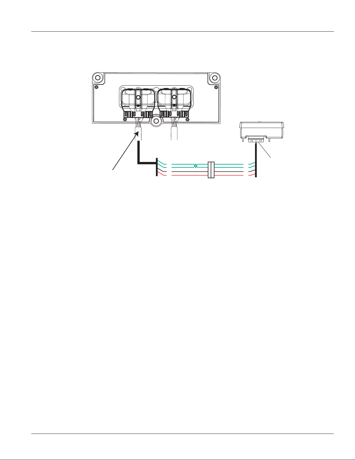
TRTS0930
Vehicle bulkhead
connector
HIL Data Link
F1
F2
28
27
Shift control
30-way connector
Vehicle Harness 38-way Connector
J3
C1
25
31
All OEM responsible wiring shown is "typical". Consult specific application.
(31) = +12 volt switched from TECU
(28, 27) = Communication from and to the TECU
(25) = Signal returns, grounds, and general OEM wiring
Shift Control ECU Legend
Component Identification
Fault Isolation Procedures | Fault Code 16 - High Integrity Link (HIL)
2016.01.15
© 2016 Eaton. All rights reserved
63
Page 69

Fault Code 16 - High Integrity Link (HIL) | Fault Isolation Procedures
K
J
H
G
F
E
D
C
B
A
321
321
Volts
V
COM
A
Fault Code 16 - High Integrity Link (HIL)
TRTS0930
Purpose: Check for active and Inactive fault codes
A
and perform electrical pretest.
1. Key on.
2. Retrieve active fault codes and FMIs with Ser-
viceRanger using the 9-way diagnostic connector.
3. Perform electrical pretest, see “Electrical Pretest”
on page 12.
• If no fault codes found during the elect
rical
pretest and:
uipped with a Push Button Shift Control,
- if eq
go to Step B.
- if equipped with a Cobra Lever or an OEM
shift device, configure the Driver Interface
Type to the correct shift device type with
ServiceRanger. Go to Step V.
• If issue was repaired during electrical pretest,
go to
Step V.
Purpose: Measure voltage supply to Push Button
C
Shift Controller (PBSC).
1. Disconnect Shift Control 30-way connector.
2. Key on.
3. Measure voltage on 30-way connector Pin J3
1
Pin C
and
Purpose: Visually inspect vehicle bulkhead connec-
B
tion (if equipped).
1. Key off.
2. Inspect Bulkhead Connector for looseness, corro-
sion and contamination.
• If Bulkhead Connector is found in ser
cond
ition, go to Step C.
viceable
• If voltage is within 1.2 volts of battery
go
to Step D.
• If out of range, go to Step F.
voltage,
• If looseness, corrosion, or contamination is
fou
nd at the Bulkhead Connector, repair or
replace connector per OEM
ep V.
St
instructions. Go to
64
© 2016 Eaton. All rights reserved
2016.01.15
Page 70

TRTS0930
K
J
H
G
F
E
D
C
B
A
321
321
Volts
V
COM
A
K
J
H
G
F
E
D
C
B
A
321
321
Ohms
V
COM
A
Fault Isolation Procedures | Fault Code 16 - High Integrity Link (HIL)
Purpose: Measure signal voltages on HIL.
D
1. Disconnect Shift Control 30-way connector.
2. Key on.
3. Measure voltage on the
ector pins:
conn
- J3 and F1
- J3 and F2
Shift Controller 30-way
Purpose: Confirm the presence of terminating re-
E
sistors in the HIL.
1. Key off.
2. Measure resistance between Pin F1 and Pin F2
the Shift Controller
30-way connector
.
on
Note
: Ensure key is off for a minimum of 2 minutes
before proceeding. If unsure, disconnect battery power or remove the 30-amp inline fuse.
• If both readings are between
ep E.
St
• If any of the above requirements are not met,
go to
Step H.
2-3 volts, go to
• If resistance between Pin F1 and Pin F2
110-130 ohms,
replace Push Button Shift
Control (only if fault code is Active). Go to
Step V.
is
• If any of the above requirements are not met,
go
to Step H.
2016.01.15
© 2016 Eaton. All rights reserved
65
Page 71

Fault Code 16 - High Integrity Link (HIL) | Fault Isolation Procedures
K
J
H
G
F
E
D
C
B
A
321
321
OHMS
V
COM
A
K
J
H
G
F
E
D
C
B
A
321
OHMS
V
COM
A
28
31
24 25
29 30
15 16
26
20
34
27
32 33
18 19
7389
12 6
11 12
45
22
21
38
36
37
13 14
35
10
17
23
K
J
H
G
F
E
D
C
B
A
321
321
OHMS
V
COM
A
K
J
H
G
F
E
D
C
B
A
321
OHMS
V
COM
A
28
31
24 25
29 30
15 16
26
20
34
27
32 33
18 19
7389
12 6
11 12
45
22
21
38
36
37
13 14
35
10
17
23
TRTS0930
Purpose: Verify continuity of ground supply to
F
PBSC and test for short to ground.
1. Key off.
2. Disconnect negative battery cable.
3. Disconnect Vehicle Harness 38-way connector.
Note: On Peterbilt, disconnect Gear Display.
4. Measure resistance
ift Control 30-way connector Pin J3 and Vehi-
- Sh
between:
cle Harness 38-way connector Pin 25.
- Shift Control Shift Control 30-way connect
J3 and groun
d.
or Pin
Purpose: Verify continuity of power supply to
G
PBSC and test for short to ground.
1. Key off.
2. Measure resistance
- Shift Cont
rol 30-way connector Pin C1 and Vehi-
between:
cle Harness 38-way connector Pin 31.
- Shift Control 30-way connector Pin C1 an
ground.
d
66
• If resistance between Pin J3 and Pin 25
0.3 ohms
ground
and if resistance between Pin
is OL, go to Step G.
• If any of the above conditions are not met,
repa
ir the Vehicle Harness
Co
ntrol and TECU. Go to Step V.
between the Shift
is 0 to
J3 and
© 2016 Eaton. All rights reserved
• If resistance between Pin C1 and Pin 31
0.3 ohms and resistance
d is OL, go to Step H.
groun
between Pin
is 0 to
C1 and
• If any of the above conditions are not met,
repair the V
Cont
ehicle Harness between the
rol and TECU. Go to Step V.
Shift
2016.01.15
Page 72

TRTS0930
K
J
H
G
F
E
D
C
B
A
321
321
OHMS
V
COM
A
K
J
H
G
F
E
D
C
B
A
321
OHMS
V
COM
A
28
31
24 25
29 30
15 16
26
20
34
27
32 33
18 19
7389
12 6
11 12
45
22
21
38
36
37
13 14
35
10
17
23
K
J
H
G
F
E
D
C
B
A
321
321
OHMS
V
COM
A
K
J
H
G
F
E
D
C
B
A
321
OHMS
V
COM
A
28
31
24 25
29 30
15 16
26
20
342732 33
18 19
7389
12 6
11 12
45
22
21
38
36
37
13 14
35
10
17
23
Fault Isolation Procedures | Fault Code 16 - High Integrity Link (HIL)
Purpose: Verify continuity of HIL(+) connection to
H
the PBSC.
1. Key off.
2. Disconnect negative battery cable.
3. Disconnect Vehicle Harness 38-way connector.
4. Measure resistance
ift Control 30-way connector Pin F1 and Vehi-
- Sh
between:
cle Harness 38-way connector Pin 28.
- Shift Control 30-way connector Pin F1 an
.
ground
Purpose: Verify continuity of HIL (-) connection to
I
the PBSC.
1. Key off.
2. Measure resistance
- Shift
Control 30-way connector Pin F2 and Vehi-
between:
cle Harness 38-way connector Pin 27
- Shift Control 30-way connector
Pin F2 and
ground
d
• If resistance between Pin F2 and Pin 27 is 0 to
0.3 ohms and resistance between Pin F2
d is
groun
If
fault code is Active replace the:
• If resistance between Pin F1 and Pin 28 is 0 to
0.3 ohms
ground
and if resistance between Pin
is OL, go to Step I.
F1 and
• If any of the above conditions are not met,
repai
r the Vehicle Harness
Co
ntrol and TECU. Go to Step V.
between the Shift
- Medium-Duty Transmission Electronic Control Unit (TECU)
- Heavy-Duty Transmission Electronic Control Unit (TECU)
Go to Step V.
• If any of the above conditions are no
repair the V
Cont
OL.
ehicle Harness between the
rol and TECU. Go to Step V.
and
t met,
Shift
2016.01.15
© 2016 Eaton. All rights reserved
67
Page 73

Fault Code 16 - High Integrity Link (HIL) | Fault Isolation Procedures
Purpose: Verify repair.
V
1. Key off.
TRTS0930
2. Reconnect all connectors and negative batter
cable.
3. Key on.
4. Clear
5. Drive the vehicle and attempt to
6. Check for codes, see “Fault Code Retrieval/Clear-
codes, see “Fault Code Retrieval/Clearing”
page 5.
reset the code.
ing” on page 5.
• If no fault codes, test complete.
• If Fault Code 16 appears, go to Step A.
error in testing.
• If code
other than 16 appears, See “Fault Code
Isolation Procedure Index”
on page 8.
y
to find
on
68
© 2016 Eaton. All rights reserved
2016.01.15
Page 74

TRTS0930
Fault Isolation Procedures | Fault Code 16 - High Integrity Link (HIL)
2016.01.15
© 2016 Eaton. All rights reserved
69
Page 75

Fault Code 17 - Start Enable Relay (SER) Circuit | Fault Isolation Procedures
Fault Code 17 - Start Enable Relay (SER) Circuit
J1587: MID 130 SID 237 FMI 3, 4
J1939: SA 3 SPN 629 FMI 3, 4
Overview
This fault code indicates an electrical failure of the relay that
allows the engine to start after startup conditions are met.
When troubleshooting an Inactive code See “Product Diagnostic (PD) Mode” on page 11.
Detection
Starting at key-on and throughout operation, the Transmission Electronic Control Unit (TECU) constantly measures
the circuit. A failure mode of short to battery, short to
ground or open circuit is detected.
Fallback
The start enable relay has no fallback; however, if the failure
occurred before the engine was started, it is possible the
engine will not start.
TRTS0930
Possible Causes
This fault code can be caused by any of the following:
• Start Enable Relay
• Vehicle Harness
• TECU
70
© 2016 Eaton. All rights reserved
2016.01.15
Page 76

TRTS0930
Start
enable relay
Run to start
signal from
ignition switch
Run to
starter solenoid
26
32
4
30
87
86
85
Vehicle Harness 38-way Connector
All OEM responsible wiring shown is "typical". Consult specific application.
(30, 87) = Switched ignition
(26-87) = Latch into the ECU
(4-85) = -12 volt relay source
(32-86) = +12 volt relay source
Trans ECU Legend
Component Identification
Fault Isolation Procedures | Fault Code 17 - Start Enable Relay (SER) Circuit
2016.01.15
© 2016 Eaton. All rights reserved
71
Page 77

Fault Code 17 - Start Enable Relay (SER) Circuit | Fault Isolation Procedures
OHMS
V
COM
A
31
24 25
29 30
15 16
26
20
34
27 28
32 33
18 19
7389
12 6
11 12
4 5
22
21
38
36
37
13 14
35
10
17
23
Vehicle Harness 38-way Connector
OHMS
V
COM
A
31
24 25
29 30
15 16
26
20
34
27 28
32 33
18 19
7389
12 6
11 12
45
22
21
38
36
37
13 14
35
10
17
23
Fault Code 17 - Start Enable Relay (SER) Circuit
TRTS0930
Purpose: Verify SER is correctly wired. Check for
A
active or Inactive fault codes, noting FMI.
1. Key on.
Note: The SER must be wired according
requirements (shown on previous
GEN III
to Eaton
page) for tests to work properly. If wired differently, consult OEM for correct wiring schematic.
2. Retrieve active fault codes and FMIs with Ser-
viceRanger using the 9-way diagnostic connector.
3. What FMIs are present?
• If FMI 14 is present, go to Step
B.
• If FMI 3 or 4 are present, go to Step C.
Purpose: Visually inspect SER wiring.
B
1. Inspect OEM SER breakout connector and inspect
for
misrouted or defective OEM wiring. Inspect
OEM gu
idelines.
• If SER breakout connecto
SER, repa
Go to St
ir/replace SER per
ep
V.
r is not connected to
OEM guidelines.
per
Purpose: Measure resistance of SER through the
C
Transmission Harness.
1. Key off.
2. Disconnect negative battery cable.
3. Disconnect Vehicle Harness 38-way connector.
4. Measure resistance between Vehicle
38-way connec
resistance between
tor Pin 32 and
Vehicle Harness 38-way con-
Harness
Pin 4 and measure
nector Pin 32 and ground.
•
If resistance between Pin 32 and Pin 4 is 40 to
120 ohms
(12-volt system) or
140 to 480
ohms (24-volt system) and resistance between
and ground is OL, (if fa
32
ult code is Active)
replace the:
Medium-Duty Transmission Electronic Con-
trol Unit (TECU)
- Heavy-Duty Transmission Electronic Control Unit (TECU)
Go to Step V.
• If resistance is outside of range, go to Step B.
72
• If circuit has been bypassed, rewire per OEM
guid
elines. Go to Step
V.
• If harness is defective, repair the Vehicle Har-
ness per OEM guidelines. Go to Step
V.
© 2016 Eaton. All rights reserved
2016.01.15
Page 78

TRTS0930
85
30
86
87
87a
OHMS
V
COM
A
Fault Isolation Procedures | Fault Code 17 - Start Enable Relay (SER) Circuit
Purpose: Measure resistance of SER at the relay.
D
1. Remove SER from vehicle dash harness.
2. Measure resistance
86.
• If res
istance is 40 to 120 ohms (12-volt system) or 140 to 480 ohms (24-volt
repai
r/replace OEM wiring
Go to St
• If resistance is outside of range, replace SER.
Go to St
between SER Pin 85 and Pin
from TECU to SER.
C.
ep
V.
ep
system),
Purpose: Verify repair.
V
1. Key off.
2. Reconnect all connectors and negative batter
cable.
3. Key on.
4. Clear codes,
e 5.
pag
5. Drive the vehicle and attempt to reset the code.
6. Check for codes, see “Fault Code Retrieval/Clear-
ing” on page 5.
• If no codes, test complete.
• If Fault Code 17 appears, go to Step
error in
• If fault code other than
Code Isolat
see “Fault Code
Retrieval/Clearing” on
testing.
17 appears, See “Fault
ion Procedure Index” on page 8.
A. to find
y
2016.01.15
© 2016 Eaton. All rights reserved
73
Page 79

Fault Code 21 - Auto Neutral Park Brake Switch | Fault Isolation Procedures
Fault Code 21 - Auto Neutral Park Brake Switch
J1587: MID 130 PID 254 FMI 14
J1939: SA 3 SPN 70 FMI 14
Overview
An auto neutral feature is provided with this transmission
which forces the transmission into neutral in all instances
when the parking brake is applied. The OEM installs a normally closed T pressure switch into the existing air line to
the parking brake valve. The pressure switch output and
return wires are connected to the vehicle interface transmission Electronic Control Unit (TECU) connector. Consult
OEM for switch location.
This fault code indicates a failure of the switch that reports
engagement of the park brake. When troubleshooting an
Inactive code See “Product Diagnostic (PD) Mode” on
page 11.
Detection
Fault Code 21 is set if the switch indicates the park brake is
set while the truck is moving for more than 5 seconds, or if
the switch state doesn't match the state broadcast on
J1939, or if the switch is unstable for more than 5 seconds.
TRTS0930
Fallback
Remote throttle is disabled, and auto neutral may not work.
Possible Causes
This fault code can be caused by any of the following:
• Park brake switch
• Park brake wiring
• TECU
• Park brake hardware not installed
• J1939 reporting error
74
© 2016 Eaton. All rights reserved
2016.01.15
Page 80

TRTS0930
23
17
31
24 25
29 30
15 16
26
20
34
27 28
32 33
18 19
7389
1 26
12
4 5
22
21
38
36
37
13 14
35
Front View
Transmission ECU Connector
(Vehicle Interface)
10
11
1919191919
33
Component Identification
Fault Isolation Procedures | Fault Code 21 - Auto Neutral Park Brake Switch
Description From To
Pressure Switch Signal Wire Pin 19 Signal Wire
Pressure Switch Return Wire Pin 33 Return Wire
2016.01.15
© 2016 Eaton. All rights reserved
75
Page 81

Fault Code 21 - Auto Neutral Park Brake Switch | Fault Isolation Procedures
Fault Code 21 - Auto Neutral Park Brake Switch
TRTS0930
Purpose: Check for active or Inactive fault codes
A
and perform electrical pretest.
1. Key on.
2. Retrieve active fault codes and FMIs with Ser-
viceRanger using the 9-way diagnostic connector.
3. Perform electrical pretest, see “Electrical Pretest”
on page 12.
• If no issues found during electrical pretest
lt is still active, go to Step
the fau
• If issue was repaired during electrical pretest,
go to
Purpose: Monitor park Brake Switch in Ser-
B
viceRanger.
Step
V.
B.
and
Purpose: Remove Park Brake Switch and monitor
C
Park Brake Switch status in ServiceRanger.
1. Key off.
2. Disconnect negative battery cable.
3. Disconnect the switch.
4. Connect power and key on.
• Status changes to released, repair
switch
per OEM instructions. Go to Step
• Status remains Applied, go to Step D.
Purpose: Check for short circuits on Park Brake
D
Switch Input wiring.
1. Key off.
or replace
V.
1. Ensure vehicle park brake is set and vehicle air sys-
tem is fully charged.
2. Using the Data Monitoring function in Ser-
viceRanger, note the status of the park
• Brake
• Brake is released, go to Step E.
• Brake is fluctuating between applied and
Note: If Fault Code 21 goes Inactive when park brake is
released, a J1939 reporting error is highly probable.
Seek OEM assistance before proceeding to Step C.
is applied, go to Step
released, go to Step
G.
brake.
C.
2. Disconnect negative battery cable.
3. Disconnect the Vehicle Harness TECU 38-way con-
nector.
4. Measure resistance between the Vehicle
-way connector Pin 19 and ground.
38
• If resistance between Pin 19 and
n 10K ohm, repair Ve
less tha
uidelines. Go to Step
OEM g
• If resistance between Pin 19 and ground is
greater t
Active) replace
- Medium-Duty Transmission Electronic Con-
- Heavy-Duty Transmission Electronic Con-
Go to Step V.
han 10K ohm or open, (if fault
the:
trol Unit (TECU)
trol Unit (TECU)
V.
Harness
ground is
hicle Harness per
code is
76
© 2016 Eaton. All rights reserved
2016.01.15
Page 82

TRTS0930
Fault Isolation Procedures | Fault Code 21 - Auto Neutral Park Brake Switch
Purpose: Jump the Park Brake Switch and monitor
E
Park Brake Switch status in ServiceRanger.
1. Key off.
2. Disconnect negative battery cable.
3. Bypass the switch by placing
ections.
conn
4. Connect power and key on.
• Status changed to Applied, repair or repl
switch per
Note: The requirement is for a “normally
• Status remains Released, go to Step
OEM instructions. Go to Step
closed” switch. If the
consistently reports contrary values, a
“normally open switch” was possibly
installed in error.
a jumper at the switch
park brake status
F.
ace
V.
Purpose: Verify continuity of Park Brake switch
F
status in ServiceRanger.
1. Key off.
2. Disconnect negative battery cable.
3. Disconnect the Vehicle Harness TECU 38-way con-
nector.
4. Measure resistance between the Vehicle
-way connector Pin 33 and Pin 19.
38
• If resistance is greater than 0.3
Vehicle Harness per OEM guideli
the
Step
V.
• If resistance is 0 to 0.3 ohms, (if fault code is
Active) replace the:
-
Medium-Duty Transmission Electronic Control Unit (TECU)
- Heavy-Duty Transmission Electronic Control Unit (TECU)
Go to Step V.
Harness
ohms, repair
nes. Go to
2016.01.15
© 2016 Eaton. All rights reserved
77
Page 83

Fault Code 21 - Auto Neutral Park Brake Switch | Fault Isolation Procedures
TRTS0930
Purpose: Monitor Park Brake Switch status in Ser-
G
viceRanger.
1. Key off.
2. Disconnect negative battery cable.
3. Disconnect the switch.
4. Connect power and key on.
• Status changed to Released, repair or
switch per
• Status continues changing states, go to Step
H.
Purpose: Check for short circuits in the shift lever
H
wiring.
OEM instructions. Go to Step
replace
V.
Purpose: Verify repair.
V
1. Key off.
2. Reconnect all connectors and the negative battery
cable.
3. Key on.
4. Clear fault codes, see “Fault Code Retrieval/Clear-
ing” on page 5.
5. Drive vehicle and attempt to reset the fault code.
6. Check for codes, see “Fault Code Retrieval/Clear-
ing” on page 5.
• If no codes, test complete.
• If Fault Code 21 appears, go to Step
error in testing.
• If
fault code other than
Code Isolat
ion Procedure Index” on page 8.
21 appears, See “Fault
A. to find
1. Key off.
2. Disconnect negative battery cable.
3. Disconnect the Vehicle Harness 38-way connector.
4. Measure resistance between the Vehicle
38-way co
the resistance
• If resistance between Pin 33 and groun
• If resistance between Pin 33 and ground and
nnector Pin 33 and Pin 19 and measu
between Pin 19 and ground.
between
ohm,
guid
between
code is Active)
-
- Heavy-Duty Transmission Electronic Con-
Go to Step V.
Pin 33 and Pin 19 is less
repair the Ve
elines. Go to Step
Pin 33 and Pin 19 are OL, (if fault
Medium-Duty Transmission Electronic Control Unit (TECU)
trol Unit (TECU)
hicle Harness per OEM
V.
replace the:
Harness
re
d or
than 10K
78
© 2016 Eaton. All rights reserved
2016.01.15
Page 84

TRTS0930
Fault Isolation Procedures | Fault Code 21 - Auto Neutral Park Brake Switch
2016.01.15
© 2016 Eaton. All rights reserved
79
Page 85

Fault Code 22 - ABS CAN Message Fault | Fault Isolation Procedures
Fault Code 22 - ABS CAN Message Fault
J1587: MID 130 SID 254 FMI 9, 14
J1939: SA 3 SPN 563 FMI 9, 14
Overview
J1939 is a high-speed twisted pair 250K baud data link with
one 120 ohm resistor at each end of the link. The Transmission Electronic Control Unit (TECU) is connected to the
J1939 data link at the 38-way vehicle connector. This link is
used to transmit information to the TECU as well as communicate or receive data from the other modules on the
network like the ABS module. When troubleshooting an
Inactive code See “Product Diagnostic (PD) Mode” on
page 11.
Detection
Fault Code 22 is detected if J1939 communication from the
ABS is lost for 5 seconds and other devices are present on
J1939.
TRTS0930
Fallback
No Fallback mode; however, Hill Start Aid (HSA) will not
function, and the system may attempt a shift during wheel
slip events.
Possible Causes
This fault code can be caused by any of the following:
• J1939 datalink
• ABS module
• ABS module does not support HSA or is no
conf
igured with HSA
t
80
© 2016 Eaton. All rights reserved
2016.01.15
Page 86

TRTS0930
Typical J1939/11 data link harness
(OEM supplied)
ABS ECM
B
A
C
–J1939
+J1939
Shield
Transmission ECU
Vehicle Harness 38-way Connector
Component Identification
Fault Isolation Procedures | Fault Code 22 - ABS CAN Message Fault
2016.01.15
© 2016 Eaton. All rights reserved
81
Page 87

Fault Code 22 - ABS CAN Message Fault | Fault Isolation Procedures
Fault Code 22 - ABS CAN Message Fault
Purpose: Check for active or Inactive fault codes.
A
Contact the vehicle OEM for further directions.
1. Key on.
2. Retrieve active fault codes and FMIs with Ser-
viceRanger using the 9-way diagnostic connector
TRTS0930
• If Fault Code 22 is Active, repair ABS modu
or d
ata link per OEM guidelines.
• If Fault Code 22 is Inactive, test complete.
le
82
© 2016 Eaton. All rights reserved
2016.01.15
Page 88

TRTS0930
Fault Isolation Procedures | Fault Code 22 - ABS CAN Message Fault
2016.01.15
© 2016 Eaton. All rights reserved
83
Page 89

Fault Code 26 - Clutch Slip | Fault Isolation Procedures
Fault Code 26 - Clutch Slip
J1587: MID 130 SID 55 FMI 10
J1939: SA 3 SPN 522 FMI 10
T
RTS0930
Overview
This fault code indicates the clutch is not performing as
expected. The transmission controller detected excessive
clutch slip.
Detection
When the transmission is in gear and the clutch is fully
engaged, engine speed and input shaft speed are compared. If the engine speed is significantly different from the
input shaft speed for a period of one to two seconds, the
fault code is set.
Clutch Slip Testing
Note: It is recommended that the pilot bearing be replaced
whenever the clutch is replaced.
Note: Refer to Installation Guide TRIG1110 for a list of rec-
ommended pilot bearings.
Note: Secondary clutch failures resulting from conditions
such as pilot bearing failures, excessive torsional
vibration, or clutch abuse, are not covered under
warranty.
Note: Record Vehicle Performance Analysis every time a
clutch is replaced.
Fallback
This fault causes a downshift only fallback. Once the vehicle
is stopped, starting gear and reverse gear can be engaged;
however, the fault will clear at power down. Upshifts will be
allowed until the fault is detected again.
Possible Causes
This fault code can be caused by any of the following:
• Worn or damaged clutch
• Clutch abuse
• Low clutch torque
• Contaminated clutch disks
Additional Tools
• Clutch jack
84
© 2016 Eaton. All rights reserved
2016.01.15
Page 90

TRTS0930
Component Identification
Fault Isolation Procedures | Fault Code 26 - Clutch Slip
Driven Disc
2016.01.15
Clutch Assembly
DM Clutch
© 2016 Eaton. All rights reserved
Driven Disc and
Intermediate Plate
85
Page 91

Fault Code 26 - Clutch Slip | Fault Isolation Procedures
Fault Code 26 - Clutch Slip
T
RTS0930
Purpose: Drive vehicle under load above 1500
A
RPM. Check for active and Inactive fault codes.
1. Key on.
2. Start engine.
3. Drive vehicle under load in highest
with engine speed above 1500 RPM. At a steady
speed, quickly and fully press and hold
• If Fault Code 26 is Active,
ep
St
V.
• If Fault Code 26 is Inactive, test complete. Go
to Step
V.
replace clutch. Go to
gear possible
the throttle.
Purpose: Verify repair.
V
1. Key off.
2. Reconnect all connectors and the negative battery
cable.
3. Key on.
4. Clear fault codes, see “Fault Code Retrieval/Clear-
ing” on page 5.
5. Drive vehicle and attempt to reset the code.
6. Check for fault codes,
eval/Clearing” on page 5.
Retri
• If no fault codes, test complete.
• If fault code 26 appears go to Step
error in te
• If fault code other than
Code Isolat
sting.
see “Fault Code
A. to find
26 appears, See “Fault
ion Procedure Index” on page 8.
86
© 2016 Eaton. All rights reserved
2016.01.15
Page 92

TRTS0930
Fault Isolation Procedures | Fault Code 26 - Clutch Slip
2016.01.15
© 2016 Eaton. All rights reserved
87
Page 93

Fault Code 27 - Clutch Disengagement | Fault Isolation Procedures
Fault Code 27 - Clutch Disengagement
J1587: MID 130 SID 55 FMI 7, 13
J1939: SA 3 SPN 788 FMI 7, 13
TRTS0930
Overview
The fault code indicates that the clutch has not disengaged
as expected.
Detection
Starting at key on and throughout operation, the Transmission Electronic Control Unit (TECU) constantly measures
engine RPM and idle torque from the engine. If the engine
speed falls significantly below idle or engine torque rises
significantly above idle torque upon engaging a start gear,
the fault is set. If the vehicle is brought to a stop when in
gear and engine speed falls significantly below idle, the fault
is set.
Clutch Disengagement Test
Note: It is recommended that the pilot bearing be replaced
whenever the clutch is replaced.
Note: Refer to Installation Guide TRIG1110 for a list of rec-
ommended pilot bearings.
Note: Secondary clutch failures resulting from conditions
such as pilot bearing failures, excessive torsional
vibration or clutch abuse are not covered under warranty.
Fallback
No gear engagement from neutral if the truck is stationary;
however, if the TECU determines the vehicle is moving, it
will allow a gear engagement from neutral.
Possible Causes
This fault code can be caused by any of the following:
• Failed clutch
• Clutch thermal abuse
• Drive Disc Assembly over-speed
• Pilot Bearing failure
• Input shaft wear
• Lack of lube in Release Bearing and Bushing
Additional Tools
• Clutch jack
Note: Record Vehicle Performance Analysis every time a
clutch is replaced
88
© 2016 Eaton. All rights reserved
2016.01.15
Page 94

TRTS0930
Component Identification
Fault Isolation Procedures | Fault Code 27 - Clutch Disengagement
Driven Disc
Clutch Assembly
Driven Disc and
Intermediate Plate
DM Clutch
2016.01.15
© 2016 Eaton. All rights reserved
89
Page 95

Fault Code 27 - Clutch Disengagement | Fault Isolation Procedures
Fault Code 27 - Clutch Disengagement
TRTS0930
Purpose: Monitor and compare engine speed to
A
transmission input shaft speed in ServiceRanger.
1. Key on.
2. Start engine.
3. Confirm transmission is in neutral.
4. Raise engine speed above 1500 RPM and
e to return to idle.
engin
5. Compare engine RPM to input shaft RPM with Ser-
viceRanger, a PC-based Service Tool.
Note: Engine idle must be 700 RPM or lower.
• If the speeds match at idle and Fault Code
replace the clutch. Go to Step
Active,
• If they do not match, test complete.
allow
V.
27 is
Purpose: Verify repair.
V
1. Key off.
2. Reconnect all connectors and the negative battery
cable.
3. Key on.
4. Clear codes, see “Fault Code
e 5.
pag
5. Drive vehicle and attempt to reset the code.
6. Check for fault codes, “Fault Code Retrieval/Clear-
ing” on page 5
• If Fault Code 27 appears go to Step
error in te
• If code other than 27 appears, See “Fault
Iso
sting.
lation Procedure Index” on page 8.
Retrieval/Clearing” on
A. to find
Code
90
© 2016 Eaton. All rights reserved
2016.01.15
Page 96

TRTS0930
Fault Isolation Procedures | Fault Code 27 - Clutch Disengagement
2016.01.15
© 2016 Eaton. All rights reserved
91
Page 97

Fault Code 28 - Clutch System | Fault Isolation Procedures
Fault Code 28 - Clutch System
J1587: MID 130 SID 52, 55 FMI 3, 4, 5, 7
J1939: SA 3 SPN 788 FMI 3, 4, 5, 7
Overview
This fault code indicates either an electrical or mechanical
failure in the WetClutch system.
Detection
Starting at key-on and throughout operation, the Transmission Electronic Control Unit (TECU) constantly monitors
this circuit. A failure mode of short to battery, short to
ground or open circuit is detected.
When the WetClutch is locked after urge to move, engine
speed and input shaft speeds are compared. If the engine
speed is significantly higher than the input shaft speed for a
period of five seconds, the WetClutch is slipping.
Fallback
There is no fallback mode; however, if the failure mode is
open circuit, the engine will be disengaged from the input
shaft.
TRTS0930
Possible Causes
This fault code can be caused by any of the following:
• TECU
• Transmission Harness
• Low fluid level
• WetClutch system
92
© 2016 Eaton. All rights reserved
2016.01.15
Page 98

TRTS0930
Component Identification
Fault Isolation Procedures | Fault Code 28 - Clutch System
Transmission Harness
Transmission ECU
WetClutch System
WetClutch Fluid
2016.01.15
© 2016 Eaton. All rights reserved
93
Page 99

Fault Code 28 - Clutch System | Fault Isolation Procedures
31
24 25
29 30
15 16
26
20
34
27 28
32 33
18 19
7389
1 2 6
11 12
45
22
21
38
36
37
13 14
35
10
17
23
OHMS
V
COM
A
31
24 25
29 30
15 16
26
20
34
27 28
32 33
18 19
7389
1 2 6
11 12
45
22
21
38
36
37
13 14
35
10
17
23
OHMS
V
COM
A
Ground
Transmission Harness 38-way Connector
Fault Code 28 - Clutch System
TRTS0930
Purpose: Check WetClutch fluid level.
A
1. Key on.
2. Place the transmission in neutral.
3. Allow engine to idle at 700-800 RPM for a mini-
mum of 2 minutes.
Note: Ensure transmission fluid temperature is
to 120
degrees F (16 to 49 degrees C).
4. Check WetClutch fluid
• If fluid lev
mar
el is at or above the
k, go to Step
• If fluid level is below the COLD-ADD mark,
Correct fluid level,
level.
B.
go to Step
COLD-FULL
V..
60
Purpose: Verify continuity of the Clutch Lube Sole-
B
noid circuit.
1. Key off.
2. Disconnect the negative battery cable.
3. Disconnect the TECU 30-way connector.
4. Measure resistance between the Transmission Har-
ness 38-way connector Pin 2 and Pin 3 and
between Pin 2 and ground.
• If the resistance between 2 and 3 is 6.5 to
ohms and is resistance from Pin 2 to ground is
OL, go
to Step
C.
9.5
94
• If resistance is outside of range, go to Step D.
© 2016 Eaton. All rights reserved
2016.01.15
Page 100

TRTS0930
OHMS
V
COM
A
31
24 25
29 30
15 16
26
20
34
27 28
32 33
18 19
7389
12 6
11 12
45
22
21
38
36
37
13 14
35
10
17
23
31
24 25
29 30
15 16
26
20
34
27 28
32 33
18 19
7389
12 6
11 12
45
22
21
38
36
37
13 14
35
10
17
23
OHMS
V
COM
A
Ground
Transmission Harness 38-way Connector
Fault Isolation Procedures | Fault Code 28 - Clutch System
Purpose: Verify continuity of Clutch Solenoid cir-
C
cuit.
1. Measure resistance between the Transmission Har-
ness 38-way connector Pin 13 and Pin
between
Pin 13 and ground.
14 and
• If resistance between Pin 13 and Pin 14 is 8.5
to 12 ohms and
ground
is [OL], Replace Transmission (Onl
fault code is
resistance from Pin 13 to
Active). Go to Step
V.
• If resistance is less than 10K ohm, go to Step
D.
y if
Purpose: Verify continuity of hydraulic manifold
D
circuits.
1. Disconnect Transmission Harness located on left
side of W
2. Measure resistance between We
etClutch housing.
tClutch housing
connector pins:
- 3 and 4
- 1 and 2
OHMS
A
V
COM
4
1
3 2
• If the resistance between Pin
to 12 ohms and the
d Pin 4 is 6.5 to 9.5 ohms, go to Step
an
resistance between
4
1
3 2
1 and Pin 2 is
• If resistance is outside of range, replace transmission, Go to Step
V.
OHMS
V
Pin 3
E.
COM
8.5
A
2016.01.15
© 2016 Eaton. All rights reserved
95
 Loading...