


DCR1595SW42
DYNEX DCR1595SW42, DCR1595SW41, DCR1595SW40, DCR1595SW39, DCR1595SW38 Datasheet
...
DCR1595SW
DCR1595SW
Phase Control Thyristor
Replaces October 2000 version, DS4248-5.0 DS4248-6.1 July 2001
FEATURES
■ Double Side Cooling
■ High Surge Capability
APPLICATIONS
■ High Power Drives
■ High Voltage Power Supplies
■ DC Motor Control
■ Welding
■ Battery Chargers
VOLTAGE RATINGS
Part and Ordering
Number
DCR1595SW42
DCR1595SW41
DCR1595SW40
DCR1595SW39
DCR1595SW38
DCR1595SW37
Repetitive Peak
Voltages
V
and V
DRM
V
4200
4100
4000
3900
3800
3700
Lower voltage grades available.
DRM
Conditions
T
= 0˚ to 125˚C,
vj
I
= I
RRM
, V
& V
& V
RRM tp
= 400mA,
RSM
RRM
DRM
V
DRM
V
DSM
V
DRM
respectively
= 10ms,
=
+ 100V
ORDERING INFORMATION
When ordering, select the required part number shown in the
Voltage Ratings selection table.
For example:
DCR1595SW38
Note: Please use the complete part number when ordering and
quote this number in any future correspondance relating to your
order.
KEY PARAMETERS
V
I
T(AV)
I
TSM
DRM
(max) 3020A
(max) 53750A
4200V
dV/dt* 1000V/
dI/dt 400A/
* Higher dV/dt selections available
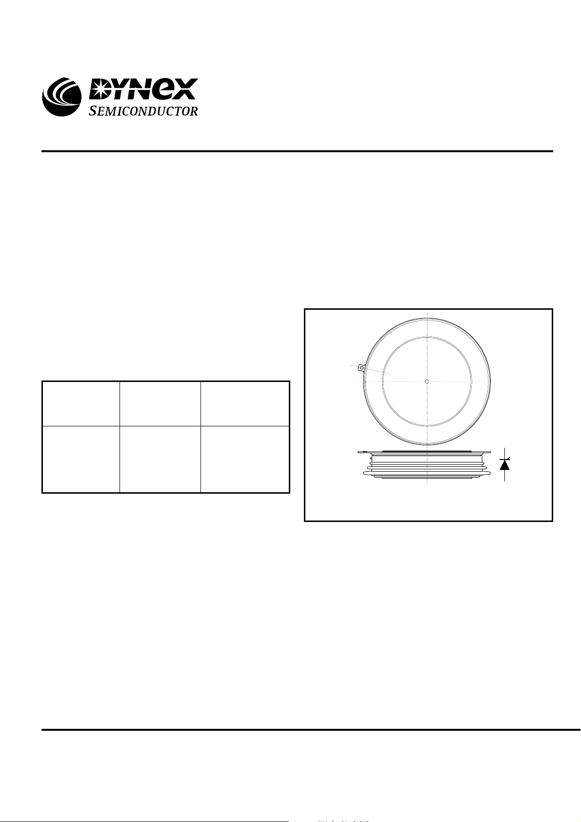
Outline type code: W
(See Package Details for further information)
Fig. 1 Package outline
µs
µs
www.dynexsemi.com
1/10
DCR1595SW
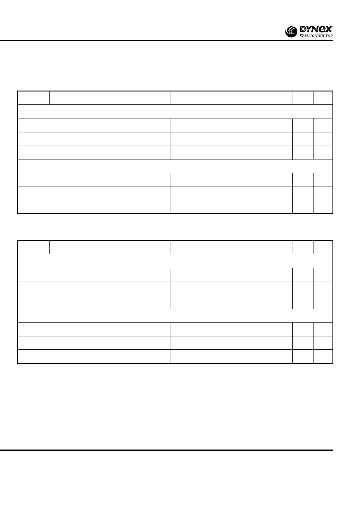
CURRENT RATINGS
T
= 60˚C unless stated otherwise.
case
Symbol
Double Side Cooled
I
T(AV)
I
T(RMS)
I
T
Mean on-state current
RMS value
Continuous (direct) on-state current
Single Side Cooled
I
T(AV)
I
T(RMS)
I
T
T
= 80˚C unless stated otherwise.
case
Mean on-state current
RMS value
Continuous (direct) on-state current
Symbol
Double Side Cooled
Parameter
Parameter
Test Conditions
Half wave resistive load
Half wave resistive load
Test Conditions
Max.
3020
-
-
4745
4370
1975
-
-
3105
2650
Max.
Units
A
A
A
A
A
A
Units
I
T(AV)
I
T(RMS)
I
T
Mean on-state current
RMS value
Continuous (direct) on-state current
Single Side Cooled
I
T(AV)
I
T(RMS)
I
T
Mean on-state current
RMS value
Continuous (direct) on-state current
Half wave resistive load
Half wave resistive load
2380
-
-
3735
3360
1530
-
-
2405
1996
A
A
A
A
A
A
2/10
www.dynexsemi.com
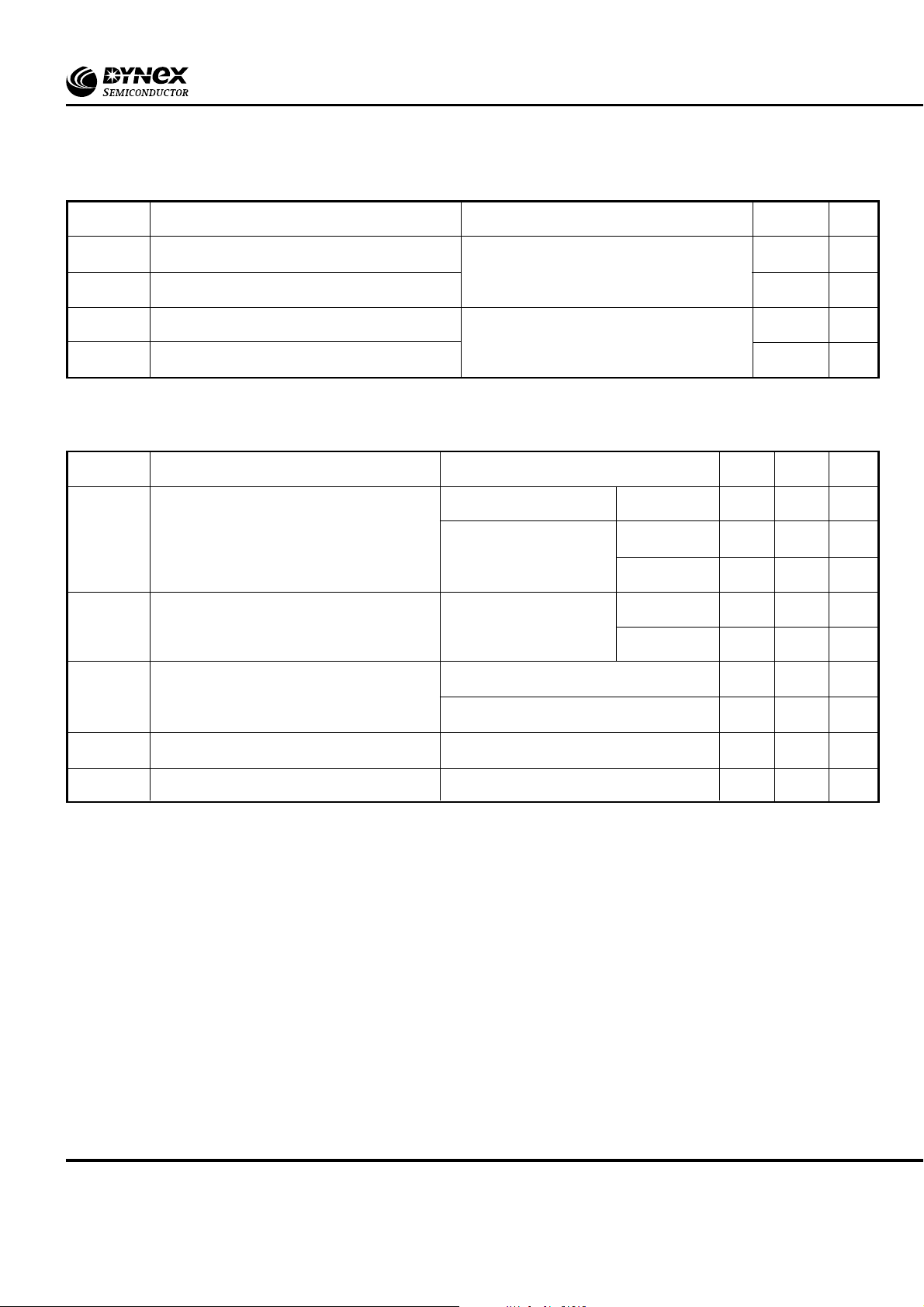
SURGE RATINGS
DCR1595SW
Symbol
I
TSM
I2t
I
TSM
I2t
Surge (non-repetitive) on-state current
2
t for fusing
I
Surge (non-repetitive) on-state current
2
t for fusing
I
Parameter
THERMAL AND MECHANICAL RATINGS
Symbol
R
th(j-c)
R
th(c-h)
Thermal resistance - junction to case
Thermal resistance - case to heatsink
Parameter
Test Conditions
10ms half sine, T
= 50% V
V
R
10ms half sine, T
V
R
case
- 1/4 sine
RRM
case
= 0
= 125˚C
= 125˚C
Test Conditions
Double side cooled DC
Single side cooled Anode DC
Cathode DC
Clamping force 70.0kN Double side
(with mounting compound) Single side
Min.
-
-
-
-
-
Max.
43.0
9.25 x 10
53.75
14.4 x 10
Max.
0.008
0.016
0.016
0.001
0.002
6
6
Units
kA
2
s
A
kA
2
s
A
Units
˚CW
˚CW
˚CW
˚CW
˚CW
T
vj
Virtual junction temperature
On-state (conducting)
Reverse (blocking)
T
stg
F
m
Storage temperature range
Clamping force
-
-
–55
63.0
135
125
125
77.0
˚C
˚C
˚C
kN
www.dynexsemi.com
3/10
 Loading...