


Owner’s manual
E
1100S / 1100
1

E
2

Hearty welcome among Ducati fans! Please accept our best compliments for choosing a Ducati motorcycle. We think you will ride your Ducati motorcycle for long journeys as well as short daily trips. Ducati Motor Holding S.p.A. wishes you smooth and enjoyable riding.
We are steadily doing our best to improve our “Technical Assistance” service. For this reason, we recommend you to strictly follow the indications given in this manual, especially for motorcycle running-in. In this way, your Ducati motorbike will surely give you unforgettable emotions.
For any servicing or suggestions you might need, please contact our authorised service centres.
Moreover, we have a new service for the ducatisti and lovers that is available for any suggestions and useful advice.
Enjoy your ride!
Note
Ducati Motor Holding S.p.A. declines any liability whatsoever for any mistakes incurred in drawing up this manual. The information contained herein is valid at the time of going to print. Ducati Motor Holding S.p.A. reserves the right to make any changes required by the future development of the above-mentioned products.
E
For your safety, as well as to preserve the warranty, reliability and worth of your motorcycle, use original Ducati spare parts only.
Warning
This manual forms an integral part of the motorcycle and - if the motorcycle is resold - must always be handed over to the new owner.
3

Table of contents
E
General 6 |
|
Warranty |
6 |
Symbols |
6 |
Useful information for safe riding 7 |
|
Carrying the maximum load allowed 8 |
|
Identification data 9 |
|
Controls |
10 |
|
|
Position of motorcycle controls |
10 |
||
Instrument panel |
11 |
|
|
LCD unit functions |
13 |
|
|
LCD – Parameter setting/display |
15 |
||
The immobilizer system 35 |
|
||
Code Card 36 |
|
|
|
Immobilizer override procedure |
37 |
||
Duplicate keys |
39 |
|
|
Key-operated ignition switch and steering lock 40
Clutch lever |
42 |
RH switch |
43 |
Throttle twistgrip |
43 |
Front brake lever |
44 |
Rear brake pedal |
45 |
Gear change pedal |
45 |
Setting the gear change and rear brake pedals 46
Main components and devices 48
Position on the vehicle 48 |
|
Fuel tank plug 49 |
|
Opening the seat 50 |
|
Opening the glove compartment door 51 |
|
Side stand 52 |
|
Front fork adjusters 53 |
55 |
Rear shock absorber adjusters |
|
Rear-view mirror adjustment |
56 |
Changing motorcycle track alignment (1100S) 57
Directions for use 59
Running-in recommendations 59
Pre-ride checks 61 |
|
||
Starting the engine 62 |
|
||
Moving off |
64 |
|
|
Braking |
64 |
|
|
Stopping the motorcycle |
65 |
||
Parking |
65 |
|
|
Refuelling |
66 |
67 |
|
Tool kit and accessories |
|||
4
Main maintenance operations 68
Removing the fairing |
68 |
|
|
|
||
Checking brake and clutch fluid level 70 |
||||||
Checking brake pads for wear |
72 |
|
||||
Lubricating joints |
73 |
|
|
|
|
|
Adjusting throttle control free play 74 |
|
|||||
Charging the battery |
75 |
|
76 |
|
||
Checking drive chain tension |
|
|||||
Chain lubrication |
77 |
|
|
|
|
|
Replacing the headlight bulbs |
78 |
|
||||
Replacing the rear turn indicator bulbs |
80 |
|||||
Replacing the number plate light bulbs |
81 |
|||||
Beam setting |
82 |
|
|
|
|
|
Tubeless tyres |
84 |
|
86 |
|
|
|
Checking engine oil level |
|
|
||||
Cleaning and replacing the spark plugs |
87 |
|||||
Cleaning the motorcycle |
88 |
|
|
|||
Storing the bike away |
89 |
|
|
|
||
Important notes |
|
89 |
|
|
|
|
Maintenance 90
Scheduled maintenance chart: operations to be performed by the dealer 90
Scheduled maintenance chart: operations to be performed by the customer 93
Technical data |
94 |
|
|||
Overall dimensions (mm) |
94 |
|
|||
Weights |
94 |
|
|
|
|
Top-ups |
95 |
|
|
|
|
Engine |
96 |
|
|
|
|
Timing system 96 |
|
|
|||
Performance data |
97 |
|
|
||
|
|
||||
Spark plugs |
97 |
|
|
E |
|
Fuel system |
97 |
|
|
||
Exhaust system |
97 |
|
|
||
Transmission |
98 |
|
|
|
|
Brakes |
99 |
|
|
|
|
Frame 100 |
|
|
|
|
|
Wheels |
100 |
|
|
|
|
Tyres 100 |
|
|
|
|
|
Suspensions |
101 |
|
|
||
Available colours |
101 |
|
|
||
Electric system 102 |
|
|
|||
For United States of America Version |
|||||
Only |
107 |
|
|
|
|
Routine maintenance record 116
5

General
E
Warranty
In your own interest, and in order to guarantee product reliability, you are strongly advised to refer to our authorised Dealers and workshops for any servicing requiring particular technical expertise.
Our highly skilled staff have access to the implements required to perform any servicing job at best, and use Ducati original spare parts only as the best guarantee for full interchangeability, smooth running and long life.
All Ducati motorcycles come with a “Warranty Card”. The warranty does not apply to the motorcycles used in competitions. No motorcycle part may be tampered with, altered, or replaced with parts other than original Ducati spare parts during the warranty period, or the warranty will be automatically invalidated.
Symbols
Ducati Motor Holding S.p.A. advises you to read this booklet carefully so as to become familiar with your motorcycle. In case of any doubts, please call a Ducati Dealer or Authorised Workshop. The information contained herein will prove useful on your trips - and Ducati Motor Holding S.p.A. wishes you smooth, enjoyable riding - and will help you keep the performance of your motorcycle unchanged for a long time. This manual contains some special remarks:
Warning
Failure to comply with these instructions may put you at risk and lead to severe injury or death.
Important
Possibility of damaging the motorcycle and/or its components.
Note
Additional information on the job being carried out.
The terms right and left are referred to the motorcycle viewed from the riding position.
6

Useful information for safe riding
Warning
Read this section before riding your motorcycle.
Accidents are frequently due to inexperience. Always make sure you have your licence with you when riding; you need a valid licence to be entitled to ride your motorcycle.
Do not lend your motorcycle to inexperienced riders or who do not hold a valid licence.
Both rider and pillion passenger must always wear a safety helmet.
Wear proper clothing, with no loose items or accessories that may become tangled in the controls or limit your zone of vision.
Never start or run the engine indoors. Exhaust gases are poisonous and may lead to loss of consciousness or even death within a short time.
Both rider and pillion passenger should keep their feet on the footpegs when the motorcycle is in motion.
Always hold the handlebars firmly with both hands so you will be ready for sudden changes of direction or in the road surface. The pillion passenger should always hold on to the special handles onto tail guard with both hands.
Ride within the law and observe national and local rules. Always respect speed limits where these are posted. However, always adjust your speed to the visibility, road and traffic conditions you are riding in.
Always signal your intention to turn or pull to the next lane in good time using the suitable turn indicators.
Be sure you are clearly visible and do not ride within the blind spot of vehicles ahead.
Be very careful when tackling road junctions, or when riding in the areas near exits from private grounds, car parks or on slip roads to access motorways.
Always turn off the engine when refuelling.
Be extremely careful not to spill fuel on the engine or on the exhaust pipe when refuelling.
Do not smoke when refuelling. E While refuelling, you may inhale noxious fuel vapours.
Should any fuel drops be spilled on your skin or clothing, immediately wash with soap and water and change your clothing.
Always remove the key when you leave your motorcycle unattended.
The engine, exhaust pipes, and mufflers stay hot for a long time.
Warning
The exhaust system might be hot, even after engine is switched off; pay particular attention not to touch exhaust system with any body part and do not park the vehicle next to inflammable material (wood, leaves etc.).
Park your motorcycle where no one is likely to hit it and use the side stand.
Never park on uneven or soft ground or your motorcycle may fall over.
7

Carrying the maximum load allowed
Your motorcycle is designed for long-distance riding, carrying the maximum load allowed in full safety.
Even weight distribution is critical to preserving these safety features and avoiding trouble when performing sudden manoeuvres or riding on bumpy roads.
Information about carrying capacity
E The total weight of the motorcycle in running order including rider, pillion passenger, luggage and additional accessories should not exceed:
390 Kg.
Arrange your luggage or heavy accessories in the lowest possible position and close to motorcycle centre.
Be sure to secure the luggage to the supports provided on the motorcycle as firmly as possible. Improperly secured luggage may affect stability.
Never fix bulky or heavy objects to the handlebar or to the front mudguard as this would affect stability and cause danger.
Do not insert any objects you may need to carry into the gaps of the frame as these may foul moving parts.
Make sure the tyres are inflated to the proper pressure indicated at page 84 and that they are in good condition.
8

Identification data
All Ducati motorcycles have two identification numbers, for frame (fig. 1) and engine (fig. 2).
Frame number
Engine number
Note
These numbers identify the motorcycle model and should always be indicated when ordering spare parts.


 E
E


 fig. 1
fig. 2 |
9 |
Controls
4 |
E
Warning
This section details the position and function of all the controls you need to drive your motorcycle. Be sure to read this information carefully before you use the controls.
Position of motorcycle controls (fig. 3) |
2 |
1) |
Instrument panel. |
|
|
2) |
Key-operated ignition switch and steering lock. |
9 |
|
3) |
Left switch. |
||
|
|||
4) |
Clutch lever. |
|
|
5) |
Rear brake pedal. |
|
|
6) |
Right switch. |
|
|
7) |
Throttle twistgrip. |
|
|
8) |
Front brake lever. |
|
|
9) |
Gear change pedal. |
|
3 |
1 |
8 |
7 |
6 |
5 |
fig. 3
10
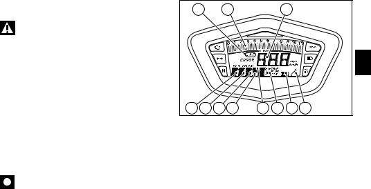
Instrument panel (fig. 4)
1)LCD, (see page 13)
2)Revolution counter (rpm).
Shows the engine rotation speed/minute.
3)Neutral light N (green). Comes on when in neutral position.
4)Fuel warning light  (yellow).
Comes on when there are about 3 litres of fuel left in the tank.
5) Indicators repeater lights  (green).
The repeater light of whichever turn indicator is on comes on and flashes.
6) Engine oil pressure light  (red).
Comes on when engine oil pressure is too low. It briefly comes on when the ignition is switched to ON and normally goes out a few seconds after engine starts.
It may shortly come on when the engine is hot, however, it should go out as the engine revs up.
Important
If this light (6) stays on, stop the engine or it may suffer severe damage.
7) High beam light  (blue). Comes on when high beam is on.
8 |
9 |
2 |
1 |
6 |
|
|
|
|
E |
5 |
3 |
4 |
7 |
fig. 4 |
|
|
|
|
8)“Engine diagnosisEOBD” light  (amber yellow). When on, this light is used to signal the presence of errors and sometimes the consequent engine disabling.
9)Limiter light - OVER REV
It comes on steady at 800 rpm (engine rpm) below the limiter threshold.
It starts to flash upon reaching the limiter threshold.
11
10) |
Button A/B. |
|
|
Button used to display and set instrument panel parameters. |
A |
||
It has two positions: A"▲" and B "▼". |
|||
|
|||
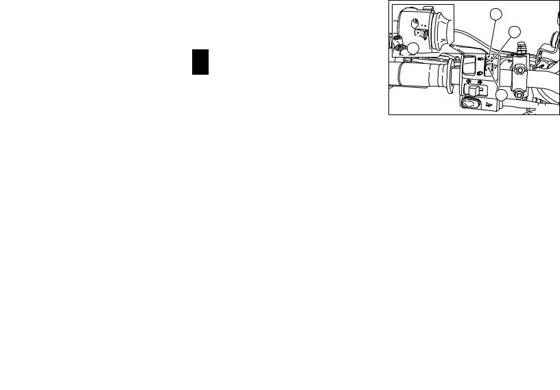
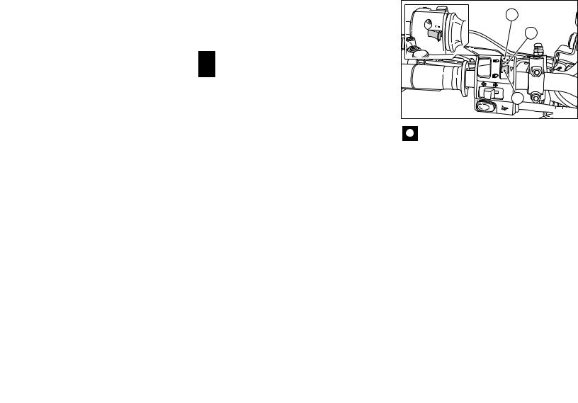
11) |
High-beam flasher button FLASH (fig. 5) |
10 |
|
The high-beam flasher button may also be used to control the |
|||
LAP functions and the instrument panel USB data logger. |
|
||
|
|
11 |
|
E |
|
|
|
|
|
B |
|
|
|
fig. 5 |
|
12
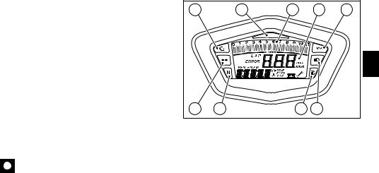
LCD unit functions
Warning
Stop the motorcycle before using the instrument panel controls. Never operate the instrument panel controls while riding.
1)Speedometer. Gives road speed
2)Odometer.
Gives total distance covered. 3) Trip meter.
This function indicates the distance covered since the meter was last reset (TRIP).
4) Trip fuel meter.
Gives total distance travelled on fuel reserve.
5)Clock.
6)Lap timer.
7)Engine rpm indicator (RPM).
8)Battery voltage indicator (BATT).
9)Oil temperature indicator.
This function indicates engine coolant temperature.
Important
Never use the vehicle when the temperature reaches max. value or the engine might damage.
11 |
7 |
1 |
E
2 |
3 |
4 |
5 |
6 |
9 |
8 |
10 |
fig. 6 |
13

10) Service warning (fig. 6).
This indicator comes on to indicate that the vehicle is due for service.
It stays on until it is reset at an Authorised Ducati Workshop as part of the service procedure.
11) LAP /USB function (fig. 6).
Indicates when the USB data logger and the LAP function are E on.
Important
The instrument panel allows the diagnosis of the electronic injection/ignition system. These menus are for trained personnel only; do not use them for any reason whatsoever. Should you accidentally enter this function, turn the key to OFF and contact an authorised Ducati Service Centre to have the vehicle inspected.
14
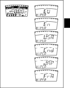
LCD – Parameter setting/display
When the key is turned from OFF to ON, the Dashboard turns on all LCD digits for one second and all warning lights one by one.
It then switches to "normal" display mode showing the model indication in place of the odometer readout and the version (EU, UK, USA, CND, FRA, JAP) for 2 seconds.
Model is displayed once as scrolling text.
CHECK 1 |
CHECK 2 |
E
fig. 7
15
|
Upon Key-On, the Dashboard always displays the following |
|
|
information (and any functions activated previously are |
A |
|
deactivated): |
|
|
|
|
|
Odometer |
1 |
|
Speed |
|
|
Engine rpm |
|
E |
With the button (1fig. 8, fig. ) set to B “▼”, the Odometer |
|
readout will cycle through the following functions: |
|
|
|
TRIP |
|
|
TRIP FUEL (only if active) |
|
|
Clock |
|
|
T.OIL (only displayed when engine is ON) |
B |
|
until cycling back to the TOT function. |
|
|
|
|
|
Pressing button (1fig. 8, fig. ) in position A “▲“ gives access |
fig. 8 |
|
|
|
|
to the MENU and the following functions are displayed one |
Important |
|
after another: |
|
|
Error (only if active) |
This menu is only active when the vehicle is stopped; |
|
RPM |
if this MENU is open while the vehicle is running, the |
|
BATT |
instrument panel will exit it automatically and go back to the |
|
LAP (OFF or ON) |
start-up display screen; you may exit the menu at any time |
|
LAP MEM |
by holding button (1, fig. 8) depressed in position A “▲” for |
|
Clock setup |
3 seconds. |
|
code (only if active) |
|
16

Total distance covered indicator: "Odometer"
This function shows the total distance covered by the vehicle.
Upon Key-On, the system automatically enters this function. The odometer reading is stored permanently and cannot be reset for any reason.
When the reading reaches 99999 Km (or 99999 mi), "99999" is displayed permanently.
Km
E
miles
fig. 9
17
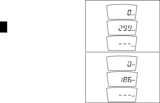
“Speed” indicator
This function shows vehicle speed.
Speed indication is obtained from actual speed information (in km/h) from the ECU increased by 8%.
Maximum speed displayed is 299 km/h (186 mph).
Over 299 Km/h (186 mph), the instrument panel will show a string of dashes " - - - " (not flashing).
E
Km / h
mph
fig. 10
18
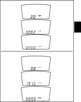
"TRIP" meter
This function shows the distance travelled since the Trip meter was last reset.
Holding button (1fig. 8, fig. ) pressed in position B “▼“ for 3 seconds when this function is displayed resets the trip meter.
When the reading exceeds 999.9, distance travelled is reset and the meter automatically starts counting from 0 again. If the dealer changes the measurement unit, the distance travelled in this function is reset and the meter starts counting from 0 again, with the new measurement units.
Km
E
miles
fig. 11
19
Distance travelled on fuel reserve: "TRIP FUEL"
This function shows the distance travelled on fuel reserve. When the fuel light comes on, the display automatically switches to the TRIP FUEL indicator. Trip fuel reading remains stored even after Key-Off until the vehicle is refuelled.
Count is interrupted automatically as soon as fuel is topped up to above minimum level.
E When the reading exceeds 999.9, distance travelled is reset and the meter automatically starts counting from 0 again.
Km
miles
fig. 12
20
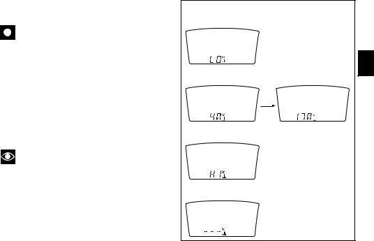
Engine coolant temperature indicator
It shows engine coolant temperature:
Important
This indication is only active when the engine is running.
-if reading is equal to -40 °C (°F -104) or lower, the display shows flashing hyphens ("---");
-if reading is between -39 °C (°F -102) and +39 °C
(°F +102), the word "LO" comes on steady on the display;
-if reading is between +40 °C (°F +104) and +170 °C (°F +338), the display shows temperature reading (on steady);
-if reading is +171 °C (°F +340) or higher, the word "HI" is shown flashing on the display;
-In case of sensor FAULT, flashing hyphens ("---") are displayed.
Note
When temperature is +171 °C (°F +340) or higher, the instrument panel will automatically switch from the set function to the flashing “HI” display.
STEADY READING |
|
|
E |
STEADY READING |
STEADY READING |
FLASHING READING |
|
FLASHING READING |
|
|
fig. 13 |
|
21 |
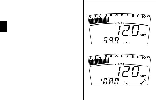
Maintenance indicator
It shows service intervals (service).
Indicator ( ) comes on to indicate that the vehicle is due for service.
The display shows the service reminder at the following intervals:
when the odometer reaches 1000 Km; every 12,000 Km.
E The indication remains displayed until it is reset.
When the message appears, contact an authorised dealer or service centre.
fig. 14 |
22
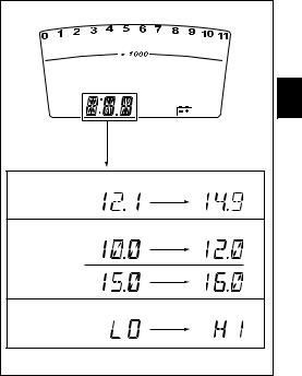
Battery voltage indicator (BATT)
This function provides battery voltage indication.
To view this function, access the menu and enter the "BATT" page.
The instrument panel display shows battery voltage indication as follows:
-if voltage is between 12.1 and 14.9 Volt, the reading is on steady;
-if voltage is between 10.0 and 12.0 Volt or between 15.0 and 16.0 Volt, the reading will be flashing;
-if voltage is 9.9 Volt or less, the word " LO " is shown flashing and the “Engine DiagnosisEOBD” light (8, fig.
4)comes on;
-if voltage is = 16.1 Volt or higher, the word HI is shown flashing and the “Engine DiagnosisEOBD” light (8, fig.
4)comes on.
E
STEADY STEADY
STATUS 1
FLASHING FLASHING
STATUS 2
FLASHING FLASHING
STATUS 3
fig. 15
23
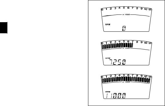
Engine idle RPM indication (RPM)
This function digitally displays engine idle rpm.
To view this function, access the menu and enter the "RPM" page.
In addition to the rev counter scale at the top, the instrument panel display shows engine rpm as a numeric value for improved accuracy when setting idle rpm.
E
fig. 16
24
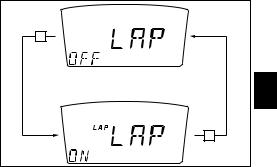
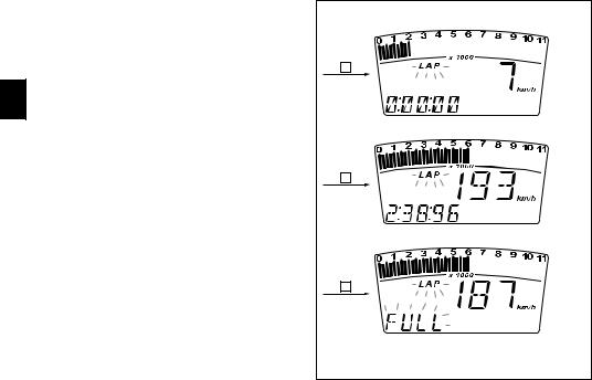
LAP timer
This function lets you display lap times.
To enable this function, enter the menu and set the "LAP"
function to "On" by holding button (1, fig. 8) pressed in B position B “▼“ for 3 seconds.
Once you have set the LAP function to On, exit the menu (press push-button (1, fig. 8) to A “▲” for 3 seconds); the system will exit the menu automatically at any vehicle speed other than 0.
The lap timer is started and stopped using the high-beam flasher button FLASH (12, fig. 5) on the LH switch.
Each time the FLASH push-button (12, fig. 5) is pressed on LH switch when the LAP function is active, the display will show lap time for 10 seconds, and then reverts to standard display mode.
Up to 30 lap times can be stored.
When the memory is full, each time the FLASH push-button (12, fig. 5) is pressed on the LH switch, the word FULL is shown flashing for 3 seconds instead of lap time until stored times are reset.
E
B
fig. 17
25
When the LAP function is set to Off in the menu, the current "lap" is not stored.
The LAP function is disabled automatically if the key is turned to Off (Key-Off) while it is active and the current "lap" is not stored even though the lap timer had been active before KeyOff.
If the lap timer is not stopped, it will roll over upon reaching 99 minutes, 59 seconds and 99 hundredths; the lap timer
E starts counting from 0 (zero) and will keep running until the function is disabled.
If the LAP function is enabled without resetting the "memory" and there are less than 30 laps stored in the memory (for instance: 18 laps stored), the display will store new laps until the memory is full (in this instance, 12 more laps).
This function only lets you view lap times; lap times are stored in the Lap Memory function.
C |
|
(1st time) |
x 10 sec |
|
|
C |
|
(2nd time) |
x 10 sec |
|
|
C |
|
(32nd time |
|
onwards, |
x 3 sec |
times reset |
|
excluded) |
|
|
fig. 18 |
26
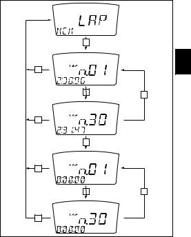
Stored data display (LAP Memory)
Displays data stored using the LAP function: lap number and lap time.
To view stored lap times, enter the menu and go to page "LAP MEM".
In this menu page, press button (1, fig. 8) in position B “▼“ to view the "1st lap"; the display will show lap number and lap time.
Press button (1, fig. 8) in position B “▼“ repeatedly to scroll through the 30 laps stored until returning to the 1st lap.
If button (1, fig. 8) is hold depressed in position B “▼“ for 3 seconds while viewing lap times, the display will instantly reset all stored lap times and the LAP function is disabled automatically if active.
To exit the stored lap time display mode, press button (1, fig. 8) in position A “▲”.
If no lap is stored in the memory, the display will scroll through 30 laps with all lap times reading "00.00.00".
If the engine reached the limiter threshold during a lap, the corresponding light (10, fig. 4) comes on while viewing stored lap times.
B
E
A
B |
(x 29 times) |
|
|
B |
|||
|
|
||
|
|
|
A
B (x 3 sec)
A
B |
(x 29 times) |
B |
A
fig. 19
27

USB Data Logger
This function lets you activate the USB data logger: the data logger must be connected to vehicle wiring.
To enable the data logger, enter the menu and set the "LAP" function to "ON" by holding button (1, fig. 8) pressed in position B “▼“.
The START/STOP control for the data logger lap separator is the high-beam flasher button FLASH (12, fig. 5) on the LH
E switch.
If the key is turned to Off (Key-Off) while the LAP function is active and the (USB) data logger is operating, the function is disabled automatically
28
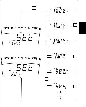
Clock setting function
To set the clock, enter the menu page "TIME Set". Holding button (1, fig. 8,) pressed in position B “▼“ for 3
seconds in this menu page gives access to the setup mode. When you access this function, the word "AM" flashes; pressing button (1, fig. 8) in position B "▼" switches to "PM" (flashing); pressing (1, fig. 8) in position B "▼" returns to the previous step (if clock time is 00:00, it will switch to 12:00 when you toggle from AM to PM);
pressing button (1, fig. 8) in position A "▲" gives access to the hour setting mode; hours start to flash. At each press of the button in position B "▼", hours will increase by 1 unit and then roll over to 0; if the button is held depressed in position B "▼", hour setting will increase by 1 hour per second (hours do not flash when the button is held depressed).
pressing button (1, fig. 8) in position A "▲" gives access to the minute setting mode; minutes start to flash. At each press of the button in B "▼", minutes increase by 1 unit and then roll over to 0; if the button is held depressed in position B "▼", minutes increase by 1 minute per second and then roll over to 0. If the button is held depressed in position B "▼" for over 5 seconds, minutes will increase by 1 minute every 100ms (while the button is held depressed in position B "▼", seconds will not flash).
Pressing the button in position A "▲", exits setup mode and the new time is displayed.
B |
(x 3 sec) |
Flashing |
|
|
|
||
|
B |
B |
|
|
|
Flashing |
|
|
|
A |
E |
|
A |
|
|
|
|
Flashing |
|
|
B |
|
|
|
|
A |
|
|
|
sett |
|
|
A |
|
|
|
|
Flashing |
|
|
B |
|
|
|
|
A |
|
|
|
sett |
|
|
|
A |
|
|
|
fig. 20 |
|
|
|
29 |
|
 Loading...