


Owner's manual
DUCATISUPERBIKE
848

Use and maintenance manual
E
848
1

E
2

Welcome to the world of Ducati enthusiasts! We congratulate you on your excellent choice of motorcycle. We are sure that you will use your Ducati for longer journeys as well as short daily trips, but however you use your motorcycle, Ducati Motor Holding S.p.A wishes you an enjoyable ride.
Ducati Motor Holding S.p.A. recommends that you adhere strictly to the instructions in this manual, especially those regarding the running-in period. This will ensure that your Ducati motorcycle will continue to be a pleasure to ride.
For repairs or advice, please contact one of our authorized service centres.
We also provide an information service for all Ducati owners and enthusiasts for any advice and suggestions you might need.
Enjoy the ride!
Notes
Ducati Motor Holding S.p.A. cannot accept any liability E for errors that may have occurred in the preparation of this manual. All information in this manual is valid at the time of going to print. Ducati Motor Holding S.p.A. reserves the right
to make any modifications required due to the ongoing development of their products.
For safety and reliability, to avoid invalidating the warranty and to maintain the value of your motorcycle, use only original Ducati spare parts.
Warning
This manual is an integral part of the motorcycle and, if ownership of the motorcycle is transferred to a third party, the manual must be handed over to the new owner.
3

E Table of contents
General indications |
6 |
|
Warranty |
6 |
|
Symbols |
6 |
|
Useful road safety information |
7 |
|
Riding with a full load 8 |
|
|
Identification data 9 |
|
|
Controls |
10 |
|
|
||
Position of the motorcycle controls 10 |
|||||
Instrument panel |
11 |
|
|
||
LCD – Main functions 13 |
|
|
|||
LCD – How to set/display parameters 15 |
|||||
The immobilizer system 38 |
|
|
|||
Code card |
39 |
|
|
|
|
Immobilizer override procedure |
40 |
||||
Duplicate keys |
42 |
|
|
||
Ignition switch and steering lock |
43 |
||||
Left-hand handlebar switch |
44 |
|
|||
Clutch lever |
45 |
|
|
|
|
Right-hand handlebar switch |
46 |
|
|||
Throttle twistgrip |
46 |
|
|
||
Front brake lever |
47 |
|
|
||
Rear brake pedal |
48 |
|
|
||
Gearchange pedal |
48 |
|
|
||
Adjusting the position of the gearchange and rear brake pedals 49
Main components and devices 51
Position on motorcycle 51
Fuel tank filler cap |
52 |
|
Seat lock |
53 |
|
Sidestand |
54 |
|
Front fork adjusters |
55 |
|
Rear shock absorber adjusters 57
Riding the motorcycle 59
Running-in precautions |
59 |
||
Pre-ride checks 61 |
|
||
Starting the engine 62 |
|
||
Moving off |
64 |
|
|
Braking |
64 |
|
|
Stopping the motorcycle |
65 |
||
Parking |
65 |
|
|
Refuelling |
66 |
67 |
|
Toolkit and accessories |
|||
Main Maintenance Operations 68
Removal of the fairings 68 |
|
|
Checking and topping up the coolant 72 |
|
|
Checking the brake and clutch fluid level |
73 |
|
Checking the brake pads for wear 75 |
|
|
Lubricating cables and linkages 76 |
|
|
Adjustment of the throttle cable free play |
77 |
|
Charging the battery 78 |
79 |
|
Checking the chain tension |
|
|
Lubricating the drive chain |
79 |
|
4
Changing the high and low beam bulbs |
80 |
||||
Changing the sidelight bulb |
82 |
|
|||
Rear turn indicators |
83 |
|
|
||
Number plate light |
83 |
|
|
||
Headlight aim |
84 |
|
|
|
|
Rearview mirror adjustment |
85 |
|
|||
Tubeless tyres |
86 |
|
|
|
|
Checking the engine oil level |
88 |
|
|||
Cleaning and renewing the spark plugs |
89 |
||||
General cleaning |
90 |
|
|
||
Storing the motorcycle 91 |
|
|
|||
Important notes |
91 |
|
|
|
|
Maintenance 92
Programmed maintenance plan: operations to be carried out by the dealer 92
Programmed maintenance plan: operations to be carried out by the dealer 95
Technical data 96
Overall dimensions (mm) 96
Weights 96
Engine 98
Timing system 98
Performance data 98
Spark plugs 99
Fuel system 99
Brakes 99
Transmission 100
Frame 101
Wheels 101 |
|
|
E |
|
Tyres |
101 |
|
|
|
Suspension 102 |
|
|
||
Exhaust system |
102 |
|
||
|
||||
Colour schemes |
102 |
|
||
Electrical system |
103 |
|
||
Routine maintenance record 107 |
||||
For United States of America version |
||||
Only |
109 |
|
|
|
Reporting of safety defects 109 |
||||
Safety warnings |
109 |
|
||
Noise emission warranty 109 |
||||
Noise and exhaust emission control system information 109 |
||||
Tampering warning |
110 |
|
||
Riding safety 111 |
|
|
||
Protective apparel |
112 |
|
||
Vehicle identification number (VIN) 112 Label location 113
California evaporation emission system 115
Ducati limited warranty on emission control system 115
Routine maintenance record 118
5

E General indications |
Ducati Motor Holding S.p.A. advises you to read this manual |
|
|
|
Symbols |
|
|
carefully in order to familiarise yourself with your motorcycle. |
|
|
If in doubt, please contact a Ducati Dealer or Authorized |
|
|
Service Centre. You will find the information in the manual |
|
|
useful on trips (which Ducati Motor Holding S.p.A. hopes will |
|
|
be smooth and enjoyable), and it will help you obtain top |
|
|
performance from your motorcycle for a long time. |
|
|
This booklet uses a set of symbols with special meanings: |
Warranty
In your own interest, and in order to ensure the reliability of the motorcycle, you are strongly advised to contact a Ducati Dealer or Authorized Service Centre for any servicing that requires particular technical expertise. Our highly qualified staff have access to the specialised
tools required to perform any servicing job to the highest professional standards, using only Ducati original spare parts as the best guarantee for perfect interchangeability, smooth running and long service life.
All Ducati motorcycles come with a Warranty Booklet. However, the warranty does not apply to motorcycles used in competitions. If any motorcycle part is tampered with, modified, or replaced with parts other than original Ducati spare parts during the warranty period, the warranty is automatically invalidated.
Warning
Failure to comply with these instructions may put you at risk, and could lead to severe injury or even death.
Important
Risk of damage to the motorcycle and/or its components.
Notes
Additional information about the current operation.
References to the right or left side of the motorcycle assume you are sitting on the seat, facing forward.
6

Useful road safety information
Warning
Read this section before riding your motorcycle.
Many accidents are the result of the inexperience of the rider. Always make sure you have your licence with you; you need a valid licence that entitles you to ride a motorcycle. Do not lend your motorcycle to persons who are inexperienced or do not hold a valid licence.
Riders and passengers must always wear appropriate clothing and a safety helmet.
Do not wear loose clothes or accessories that could become tangled in the controls or limit your field of vision.
Never start or run the engine in enclosed space. Exhaust gases are toxic and may lead to loss of consciousness or even death within a short time.
The rider should keep his/her feet on the footrests when the motorcycle is in motion.
Always hold the handlebars firmly with both hands so you will be ready for sudden changes in direction or in the road surface. The pillion passenger should always hold on to the strap on the pillion seat with both hands.
Obey the legal requirements and observe national and local regulations.
Always respect speed limits where these apply, and never exceed the speed allowed by the particular visibility, road and traffic conditions.
Always signal your intention to turn or change lane in good time, using the appropriate turn signals. E Be sure you are clearly visible and avoid riding within the
blind spot of a vehicle in front of you.
Be very careful at road junctions, or when riding in areas near exits from private land or car parks, or on the slip roads to motorways.
Always turn off the engine when refuelling. Be extremely careful not to spill fuel on the engine or on the exhaust pipe when refuelling.
Do not smoke when refuelling.
While refuelling, it is possible to inhale noxious fuel vapours. Should any fuel drops be spilled on your skin or clothing, immediately wash with soap and water and change your clothing.
Always remove the key if leaving your motorcycle unattended. The engine, exhaust pipes and silencers remain hot for a long time.
Warning
The exhaust system might be hot even after engine is switched off; take special care not to touch the exhaust system with any part of your body and do not park the motorcycle next to inflammable material (wood, leaves, etc.).
Park your motorcycle where no one is likely to knock against it, and use the sidestand.
Never park on uneven or soft ground, or your motorcycle may fall over.
7

Riding with a full load
E Your motorcycle is designed for travelling over long distances with a full load in complete safety.
Even weight distribution is critical for maintaining safety standards, and to avoid getting into difficulties when making sudden manoeuvres or riding on bumpy roads.
Information on load capacity
The total weight of the motorcycle in running order with rider, luggage and additional accessories should not exceed 390 kg.
Arrange your luggage or heavy accessories in the lowest possible position and as close to centre of the motorcycle as possible.
Secure the luggage firmly to the motorcycle structure. Luggage incorrectly secured may cause the motorcycle to become unstable.
Never attach bulky or heavy objects to the top yoke or front mudguard, as this would cause dangerous instability.
Do not insert objects into gaps in the frame, where they could interfere with moving parts.
Check that the tyres are inflated to the pressure indicated on page 86 and that they are in good condition.
8
Identification data
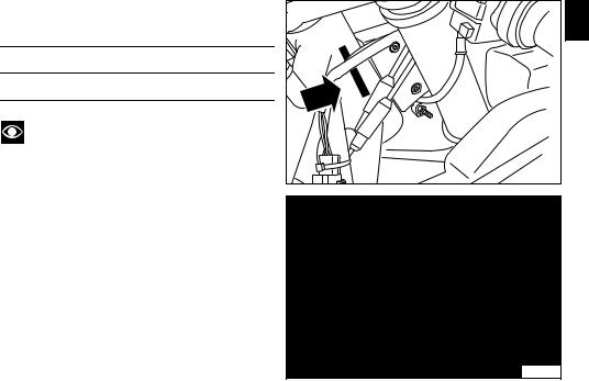
All Ducati motorcycles have two identification numbers, one for the frame (fig. 1) and one for the engine (fig. 2).
Frame number
Engine number
Notes
These numbers indicate the motorcycle model and should be quoted when ordering spare parts.
E
fig. 1
fig. 2
9
E Controls
4 |
3
2
Warning
This section shows the position and function of the controls used to drive the motorcycle. Be sure to read this information carefully before you use the controls.
Position of the motorcycle controls (fig. 3)
9
1) Instrument panel.
2) Key-operated ignition switch and steering lock.
3) Left-hand handlebar switch.
4) Clutch lever.
5) Rear brake pedal.
6) Right-hand handlebar switch.
7) Throttle twistgrip.
8) Front brake lever.
9) Gearchange pedal.
1 |
8 |
7 |
6 |
5 |
fig. 3
10
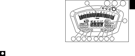
Instrument panel (fig. 4)
1)LCD (see page 13).
2)Tachometer (rpm).
Indicates engine revs per minute.
3)Neutral (N) indicator (green). Illuminates when the gearbox is in neutral.
4)Fuel warning light  (yellow).
Illuminates when there are about 3 litres of fuel left in the tank.
5) Turn signal indicator light  (green).
Illuminates and flashes when the turn signal is in operation.
6) Engine oil pressure warning light  (red). Illuminates when engine oil pressure is too low. This light should illuminate when the ignition is switched to ON and should go out a few seconds after the engine starts.
It may come on briefly if the engine is very hot, but should go out again as engine speed increases.
Important
If this light (6) stays on, stop the engine to avoid serious damage.
7) High beam warning light  (blue). Illuminates when the high beam headlight is on.
|
|
|
2 |
|
|
10A |
10B |
10C |
E |
|
|
|
|
|
|
|
|
|
|
|
|
|
|
|
|
|
|
1 |
|
5 |
9 |
8 |
6 |
3 |
4 |
7 |
5 |
fig. 4 |
|
|
|
|
|
|
|
|
|
|
8) “Engine diagnostics light”  (amber).
The engine ECU illuminates this light steadily to indicate the presence of errors leading to engine lock.
9) ”Motorcycle diagnostics” light.
Illuminates when the motorcycle diagnostics detects a problem. 10) Rev limiter indicator lights.
Indicator light 10A: illuminates steadily at 800 rpm before intervention of the rev limiter.
Indicator lights 10A + 10B: illuminate steadily 400 rpm before intervention of the rev limiter.
Indicator lights 10A + 10B + 10C: start flashing when the rev limiter is reached.
11
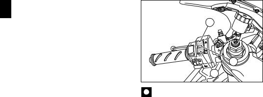
E |
11) 2-position switch A and B. |
|
Switch used for displaying and setting instrument panel |
|
|
parameters. It has two positions, A “▲” and B “▼”. |
|
|
|
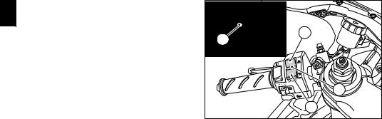
12) High beam headlight flasher switch (fig. 5). |
A |
|
The high beam headlight flasher switch is also used for |
|
|
the LAP and USB data aquisition functions. |
12 |
|
|
11 |
|
|
B |
|
|
fig. 5 |
12
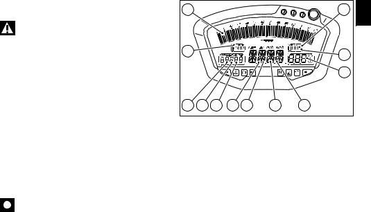
LCD – Main functions
Warning
Any adjustments to the instrument panel must only be carried out when the motorcycle is stationary. Never operate the instrument panel controls while riding the motorcycle.
1)Speedometer. Indicates road speed.
2)Odometer.
Shows total distance travelled. 3) Trip meter.
Shows the distance travelled since the last reset (TRIP A and TRIP B).
4) Fuel reserve trip counter.
Shows distance travelled on reserve fuel.
5)Clock.
6)Lap time.
7)Rev counter (RPM).
8)Recording of lap time, maximum speed and maximum rpm.
9)Battery voltage indicator (BATT).
10)Air temperature indicator.
11)Coolant temperature indicator.
Indicates engine coolant temperature.
Important
Stop riding if the temperature reaches the maximum value, otherwise the engine might be damaged.
7 |
|
|
|
|
|
9 |
E |
|
|
|
|
|
|
|
|
5 |
|
|
|
|
|
10 |
|
|
|
|
|
|
|
|
|
|
|
|
|
|
|
11 |
|
2 |
3 |
4 |
1 |
6 |
8 |
12 |
|
|
|
|
|
|
|
fig. 6 |
|
13

12) Servicing indicator (SERV) (fig. 6).
E The message “SERV” indicates that the service interval has been reached. The message is displayed only at Key-On for 5 seconds. The service indicator will be reset at an authorized Ducati Service Centre during the service.
Important
The instrument panel incorporates diagnostic functions for the electronic injection/ignition system. The relative menus are for use by trained personnel only. If you accidentally access this function, turn the key to OFF
and have the motorcycle checked at an authorised Ducati Service Centre.
14
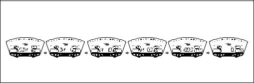
LCD – How to set/display parameters |
E |
At key-on (key turned from OFF to ON) the instrument |
|
panel activates all the digits of the LCD for 1 second and |
|
switches on the indicator lights in sequence. |
|
It then reverts to “normal” display mode and, in place of |
|
motorcycle speed, shows the model and, for 2 seconds, |
|
also the version (EU, UK, USA, CND, FRA, JAP). |
|
The model is displayed cyclically until the engine is started. |
|
ENGINE OFF |
ENGINE OFF |
ENGINE OFF |
ENGINE OFF |
ENGINE OFF |
ENGINE RUNNING |
|
|
|
|
|
fig. 7 |
|
|
|
|
|
15 |
At Key-On, the instrument panel always shows the following |
|
|
E Odometerinformation (de-activating any previously activated functions): |
|
|
Air temperature |
A |
|
Clock |
||
Speed |
|
|
Coolant temperature |
|
|
Engine rpm |
|
|
At this point, with button (1, fig. 8) in position B “▼” it is |
|
|
possible to switch from the odometer display function to |
|
|
the following functions: |
1 |
|
TRIP A |
||
|
||
TRIP B |
B |
|
TRIP FUEL (only if active) |
||
before returning to TOT (odometer function). |
fig. 8 |
|
|
If, however, you press switch (1, fig. 8) in position A “▲”, the system enters MENU mode and displays the following functions in sequence:
Error (only if active)
BATT
RPM
LAP (OFF or ON)
LAP MEM
USB (OFF or ON)
Erase USB
TIME Set
CODE (only if active)
Important
This menu is active only if the speed of the motorcycle is less than 20 km/h. If this menu is on the display and the speed of the motorcycle exceeds 20 km/h, the instrument panel automatically exits the menu and returns to the initial display. It is possible to exit the menu at any time, however, by pressing switch (1, fig. 8) in position A “▲” for 3 seconds.
16
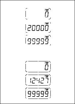
Total distance travelled indicator (odometer)
At Key-On the system automatically enters this function. The reading is saved permanently and cannot be reset. If it exceeds 99999 km (or 99999 miles), the reading “99999” remains displayed permanently.
vs. EU |
E |
||||
|
|
|
|
|
|
|
|
|
|
|
|
|
|
|
|
|
|
|
|
|
|
|
|
|
|
|
|
|
|
|
|
|
|
|
|
|
|
|
|
|
|
|
|
|
|
|
|
|
|
|
|
|
|
|
|
|
|
|
|
|
|
|
|
|
|
vs. UK v.s. USA
fig. 9
17
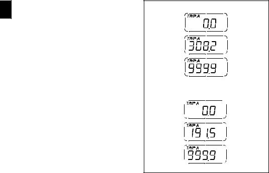
Trip meter “TRIP A”
E While in this function, if you press switch (1, fig. 8) in position B “▼“ for 3 seconds, the reading is reset.
If the reading exceeds 999.9, it is reset to zero and the count restarts automatically.
If the units of measurement set by the dealer are changed, the distance travelled is reset to zero and the count is restarted in the new units.
vs. EU
vs. UK v.s. USA
fig. 10
18
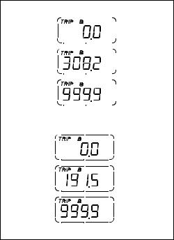
Trip meter “TRIP B”
While in this function, if you press switch (1, fig. 8) in position B “▼“ for 3 seconds, the reading is reset.
If the reading exceeds 999.9, it is reset to zero and the count restarts automatically.
If the units of measurement set by the dealer are changed, the distance travelled is reset to zero and the count is restarted in the new units.
vs. EU |
E |
||||
|
|
|
|
|
|
|
|
|
|
|
|
|
|
|
|
|
|
|
|
|
|
|
|
|
|
|
|
|
|
|
|
|
|
|
|
|
|
|
|
|
|
|
|
|
|
|
|
|
|
|
|
|
|
|
|
|
|
|
|
|
|
|
|
|
|
vs. UK v.s. USA
fig. 11
19
“TRIP FUEL” (distance travelled on reserve fuel) E indicator
When the fuel warning light comes on, the TRIP FUEL meter is activated automatically, regardless of the function displayed. If the fuel level remains in reserve, the reading is saved even after Key-Off.
The count stops automatically when the fuel level rises above reserve.
If the reading exceeds 999.9, it is reset and the count restarts automatically.
vs. EU
vs. UK v.s. USA
fig. 12
20
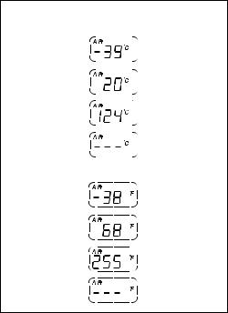
Air temperature indicator
Shows the outside air temperature. Display limits: -39 °C÷+124 °C.
In the event of a sensor FAULT (-40 °C, +125 °C or disconnected) a series of dashes “- - -” is displayed steadily and the Engine Diagnostics warning light (8, fig. 4) comes on.
|
vs. EU |
E |
||||
v.s. USA |
|
|||||
|
||||||
|
|
|
|
|
|
|
|
|
|
|
|
|
|
|
|
|
|
|
|
|
|
|
|
|
|
|
|
|
|
|
|
|
|
|
|
|
|
|
|
|
|
|
|
|
|
|
|
|
|
|
|
|
|
|
|
|
|
|
|
|
|
|
|
|
|
|
|
|
|
|
|
|
|
|
|
|
|
|
|
|
|
|
|
|
|
|
|
|
|
|
|
|
|
|
|
|
|
|
|
|
|
|
|
|
vs. USA
fig. 13
21
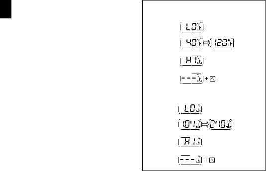
Coolant temperature indicator
E Displays the engine coolant temperature:
if the reading is less than or equal to -40 °C (-40 °F), the display shows a series of flashing dashes (“- - -”) and the Engine Diagnostics warning light comes on (8, fig. 4);
if the reading is between -39 °C (-38 °F) and +39 °C (+102 °F), the message “LO” is displayed steadily;
if the reading is between +40 °C (+104 °F) and +120 °C (+248 °F), it is displayed steadily;
if the reading is between +121 °C (+250 °F) and +124 °C (+255 °F), the message “HI” flashes on the display;
if the reading is greater than or equal to +125 °C (+257 °F), the display shows a series of flashing dashes (“- - -”) and the Engine Diagnostics warning light (9, fig. 4) comes on. In the event of a sensor FAULT, a series of dashes (“- - -”) will flash on the display and the Engine Diagnostics warning light (8, fig. 4) will illuminate.
vs. EU - vs. UK
FIXED DATUM
FIXED DATUM FIXED DATUM
FLASHING DATUM
FLASHING DATUM
VEHICLE
DIAGNOSTICS
v.s. USA
FIXED DATUM
FIXED DATUM FIXED DATUM
FLASHING DATUM
FLASHING DATUM
VEHICLE
DIAGNOSTICS
fig. 14
22
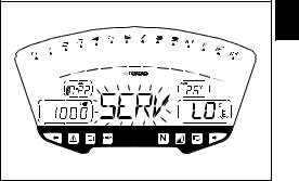
Service indicator (SERV)
Indicates that the next service is due.
The message “SERV” appears on the display at the following intervals:
after the first 1000 km on the odometer; every 12000 km on the odometer.
The message is displayed only at Key-On for 5 seconds. When the indicator appears, contact your Ducati dealer or Authorized Service Centre.
E
fig. 15
23
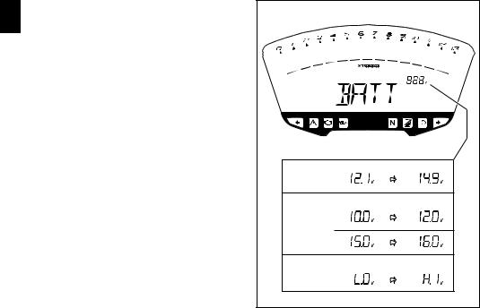
Battery voltage indicator (BATT)
E To display this function, go into the menu and select the “BATT” page.
The battery voltage reading is displayed as follows:
if the reading is between 12.1 and 14.9 Volts, it is steadily illuminated on the display;
if the reading is between 10.0 and 12.0 Volts or between 15.0 and 16.0 Volts, it flashes on the display;
if the reading is less than or equal to 9.9 Volts, the message “LO” flashes on the display and the Motorcycle Diagnostics warning light (9, fig. 4) comes on;
if the reading is greater than or equal to 16.1 Volts, the message “HI” flashes on the display and the Motorcycle Diagnostics warning light (9, fig. 4) comes on;
FIXED |
FIXED |
STATUS 1 |
|
FLASHING |
FLASHING |
STATUS 2 |
|
FLASHING |
FLASHING |
STATUS 3 |
|
|
fig. 16 |
24
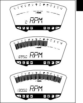
Adjusting the engine idle speed (rpm)
To display the function, access the menu and select the “RPM” page.
In addition to the upper rev counter scale, the display also shows engine rpm numerically so that you can adjust the idle speed more precisely.
E
fig. 17
25

LAP time display function
E To activate this function, go into the menu and set the “LAP” function to “On” by pressing switch (1, fig. 8) in position B “▼“ for 3 seconds.
START and STOP the timer by pressing the high beam flasher switch (12, fig. 5) on the left-hand handlebar switch. When the LAP function is active, each time you press the flasher switch, the display will show the lap time for
10 seconds, before reverting to normal mode.
You can save a maximum of 30 laps in the memory.
If the memory is full, each time you press the flasher switch, the display will not save any more lap times and will display the flashing message “FULL” for 3 seconds until the memory is reset.
fig. 18 |
26
When you switch the LAP function off from the menu, the lap in progress will not be saved.
If the LAP function is active and the display is suddenly switched off (Key-Off), the LAP function is switched off automatically (even if the timer was ON, the lap in progress is not saved).
If the timer is not stopped, when it reaches 99 minutes, 59 seconds and 99 hundredths of a second, it restarts from 0 (zero) and continues until the function is switched off.
If, however, the LAP function is switched on and the memory has not been cleared, but fewer than 30 laps have been saved (e.g. 18 laps), the display will save any remaining laps until the memory is saturated (in this case, it will save a further 12 laps).
In this function, lap time only is displayed, but other data are also saved (MAX speed, MAX rpm, rev limiter if reached) for viewing at a later date in the Lap Memory function.
E
press C
after 10 sec.
press C
after 10 sec.
fig. 19
27
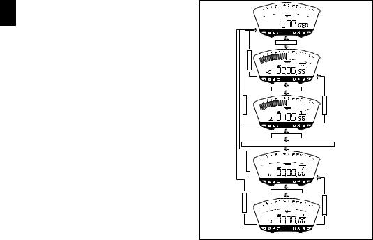
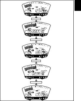
LAP Memory display
E Displays the data saved with the LAP function: lap time, MAX speed and MAX rpm.
To display the saved lap times, enter the menu and select the “LAP MEM” page.
From this menu page, if you hold pressed switch (1, fig. 8) in position B “▼“ for 3 seconds, the data for the first lap will appear. The display will show the lap number, lap time, MAX speed and the MAX rpm reached for the lap in question.
If you press switch (1, fig. 8) in position B “▼“, the display
scrolls through the 30 saved times, before returning to the 1st lap.
If you press switch (1, fig. 8) in position B “▼“ for 3 seconds while the saved times are displayed, the display immediately resets all the saved times. In this case, if the LAP function was active, it is switched off automatically.
The MAX speed saved is the maximum speed indicated on the display in Lap function.
During saving, if the MAX speed shown exceeds 299 km/h (186 mph), the speed reached is displayed (e.g. 316 km/h). If there is no reading in the memory, the 30 times are shown, with the lap timer showing “00.00.00”, MAX rpm = 0 and MAX speed = 0.
During the lap, if the engine reaches one of the two thresholds before the rev limiter or the rev limiter itself, the respective warning lights (10, fig. 4) come on during the display of the saved times.
|
press B |
|
press A |
|
press B. . x 19 |
press A |
press B |
|
B= On 3 sec. |
|
Reset of all times in memor |
|
press A |
|
press B. . x 19 |
press A |
press B |
fig. 20
28
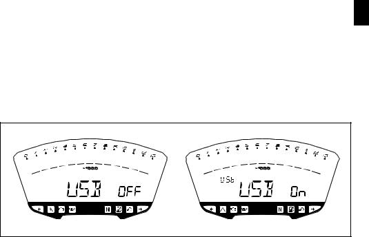
USB DAQ
This function is used to activate the data acquisition USB (not supplied as standard with this model, but can available for purchase from the Ducati sales network): the DAQ must be connected to the motorcycle wiring.
To activate the DAQ, enter the menu and set the USB DAQ to “On” by holding switch (1, fig. 8) in position B “▼“ for 3 seconds.
START and STOP the lap separator by pressing the high beam FLASH button (12, fig. 5) on the left-hand handlebar switch. If the USB function is active and the display is suddenly switched off (Key-Off), the function is switched off automatically.
E
fig. 21 |
29 |
 Loading...