


GENERAL SUMMARY
General
Information about the model
|
|
|
Technical data |
p |
y |
||
|
|
|
|
||||
|
|
|
|
|
|
|
|
|
|
|
Use and maintenance |
||||
|
|
|
|
c |
o |
|
|
|
|
|
Fairings |
|
|
|
|
|
|
|
t |
|
|
|
|
|
|
f |
|
|
|
|
|
|
|
a |
Controls - Devices |
|
|||
D |
r |
Wheels - Suspension - Brakes |
|||||
|
|
Frame |
|
|
|
|
|
|
|
|
|
|
|
|
|
Fuel / Exhaust System
Injection - ignition system
Engine
Electric system
0
A |
B |
C |
D |
E |
F |
G |
H |
L |
M |
N |
P |

General summary
Section A
A General
|
1 - How to use this manual |
3 |
B |
Layout of the manual |
4 |
2 - Symbols - Abbreviations - References |
5 |
|
|
Product specifications |
6 |
C |
3 - Hazardous Products - Warnings |
8 |
General safety rules |
8 |
|
|
General maintenance indications |
10 |
D Section B |
|
|
|
Information about the model |
|
|
1 - Identification data |
3 |
E Identification data for the Superbike 1098 |
3 |
|
F |
Section C |
|
Technical data |
|
|
|
1.1 - Technical specifications |
3 |
|
General |
3 |
G Colours |
4 |
|
|
Transmission |
4 |
|
Timing system/valves |
5 |
|
Crankshaft |
5 |
|
Cylinder/Piston |
5 |
H Gearbox |
6 |
|
|
Cooling system |
6 |
|
Front wheel |
6 |
|
Front suspension (1098) |
6 |
L |
Front suspension (1098S) |
7 |
Rear wheel |
7 |
|
|
Rear suspension (1098) |
7 |
|
Rear suspension (1098S) |
7 |
|
Hydraulic brakes |
8 |
|
Charging system/alternator |
8 |
M Injection - ignition system |
8 |
|
|
Fuel system |
8 |
|
Lights/instrument panel |
9 |
N |
1.2 - Dimensions |
10 |
|
2 - Fuel, lubricants and other fluids |
11 |
|
3 - Torque settings |
12 |
P Frame torque settings |
12 |
|
|
Engine torque settings |
13 |
2 |
1098/1098S - M.Y. 2007 - edition 00 |
|
|

General summary
4 - Service tools |
16 |
Special tools for the engine |
16 |
Special tools for the frame |
22 |
Section D
Use and maintenance
A |
B |
1 - Preliminary checks |
3 |
|
|
Running-in precautions |
3 |
C |
|
Pre-ride checks |
4 |
||
2 - Starting - Engine warmup |
5 |
|
|
Starting the engine |
5 |
D |
|
3 - Routine maintenance table |
6 |
||
|
|||
Programmed maintenance plan: operations to be carried out by the dealer |
6 |
|
|
Programmed maintenance plan: operations to be carried out by the dealer |
8 |
|
|
4 - Maintenance operations |
9 |
E |
|
Checking the engine oil level |
9 |
|
|
Changing the engine oil and filter cartridge |
10 |
|
|
Checking valve clearances |
13 |
|
|
Adjusting the valve clearances |
14 |
F |
|
Checking the coolant level |
15 |
||
Change the coolant |
16 |
|
|
Changing and cleaning the air filters |
17 |
|
|
Changing the brake fluid |
19 |
G |
|
Draining the braking circuit |
22 |
||
Fill the brake system with fluid |
24 |
|
|
Changing the clutch fluid |
27 |
|
|
Draining the clutch hydraulic circuit |
28 |
|
|
Filling the clutch circuit |
30 |
H |
|
Adjusting the steering head bearings |
32 |
||
Adjusting the chain tension |
33 |
|
|
Checking brake pad wear and changing brake pads |
35 |
|
|
Adjusting the throttle cable |
38 |
|
|
Adjusting the clutch lever and front brake lever |
40 |
L |
|
Adjusting the position of the gearchange and rear brake pedals |
41 |
||
Adjusting the front fork |
42 |
|
|
Adjusting the rear shock absorber |
43 |
|
|
Adjusting the rear ride height |
45 |
|
|
5 - Diagnostic instruments |
47 |
M |
|
Description of the Ducati Diagnostic System instrument |
48 |
|
|
Tester power supply |
50 |
|
|
DDS tester |
53 |
|
|
Checking and adjusting timing belt tension |
54 |
N |
|
Resetting the throttle position sensor (TPS) |
58 |
||
Adjusting the idle speed |
62 |
|
|
Checking the engine oil pressure |
66 |
|
|
Cylinder compression test |
71 |
P |
|
Fuel pressure test |
74 |
||
Immobilizer override procedure |
77 |
|
|
Guided diagnosis |
81 |
|
1098/1098S - M.Y. 2007 - edition 00 |
3 |
|
|

General summary
A |
B |
C |
D |
E |
F |
G |
Testing the battery charging system |
84 |
Deactivating the “maintenance” indication on the instrument panel |
87 |
Icons table |
90 |
Section E
Fairings
1 - Headlight shell - rear-view mirrors |
3 |
Removal of the rear-view mirrors |
4 |
Refitting the rear-view mirrors |
5 |
Removal of the headlight shell |
6 |
Refitting the headlight shell |
8 |
2 - Fairing panels |
11 |
Removal of the side fairings |
12 |
Removal of the front shield |
14 |
Refitting the front shield |
14 |
Refitting the side fairings |
15 |
3 - Seat - seat cowling and side panels |
17 |
Removal of the seat |
18 |
Removal of the side panels and seat cowling |
19 |
Refitting the side panels and seat cowling |
22 |
Refitting the seats |
26 |
Refitting the pillion seat |
27 |
4 - Front mudguard |
28 |
Removal of the front mudguard |
28 |
Refitting the front mudguard |
29 |
|
|
|
|
H |
|
Section F |
|
|
Controls - Devices |
|
|
|
1 - Throttle and choke controls |
3 |
|
|
|||
L |
Adjusting the throttle cable |
4 |
|
Removal of the throttle cable |
4 |
||
|
Refitting the throttle twistgrip |
5 |
|
|
2 - Hydraulic clutch control |
7 |
|
|
|||
|
|||
M |
Removal of the clutch master cylinder assembly |
8 |
|
Refitting the clutch master cylinder assembly |
9 |
||
|
Removal of the clutch slave cylinder |
11 |
|
|
Refitting the clutch slave cylinder |
13 |
|
|
|||
N |
3 - Front brake control |
16 |
Removal of the front brake master cylinder |
17 |
Refitting the front brake master cylinder |
18 |
P |
4 - Rear brake control |
19 |
Removal of the complete rear brake control |
20 |
Disassembly of the rear brake master control |
21 |
Refitting the rear brake control |
22 |
4 |
1098/1098S - M.Y. 2007 - edition 00 |
|
|

General summary
5 - Gearchange control |
23 |
Removal of the complete gearchange control |
24 |
Disassembly of the gearchange control |
25 |
Refitting the gearchange control |
26 |
Section G
Wheels - Suspension - Brakes
A |
B |
1 - Front wheel |
3 |
C |
Removal of the front wheel |
4 |
|
Overhauling the front wheel |
6 |
|
Refitting the front wheel |
9 |
|
2 - Front fork (1098) |
11 D |
Removal of the front forks |
12 |
|
Overhauling the front forks |
13 |
|
Refitting the front forks |
20 |
|
3 - Hydraulic front brake |
22 |
E |
Maintenance operations |
23 |
|
Removal of the front brake system |
24 |
|
Refitting the brake discs |
26 |
|
Overhauling the front brake components |
27 |
F |
Refitting the front brake system |
28 |
|
4 - Rear wheel |
30 |
|
Removal of the rear wheel |
31 |
G |
Overhauling the rear wheel |
32 |
|
Refitting the rear wheel |
33 |
|
5 - Rear swingarm |
34 |
|
Removal of the rear eccentric hub |
35 |
H |
Removal of the rear eccentric hub |
37 |
|
Removal of the swingarm |
39 |
|
Inspecting the swingarm pivot shaft |
41 |
|
Overhauling the rear swingarm |
42 |
|
Refitting the swingarm |
46 |
L |
6 - Hydraulic rear brake |
48 |
|
Removal of the rear brake caliper |
49 |
|
Removal of the rear brake disc |
50 |
|
Refitting the rear brake caliper |
51 |
M |
7 - Rear suspension |
52 |
|
Rear suspension system |
53 |
|
Removal of the rear shock absorber |
54 |
N |
Overhauling the rear shock absorber |
55 |
|
Removal of the rear suspension rocker arm |
56 |
|
Overhauling the rear suspension rocker arm |
57 |
|
Disassembly and overhaul of the shock absorber tie-rod |
58 |
|
Refitting the rear suspension |
59 |
P |
|
|
1098/1098S - M.Y. 2007 - edition 00 |
5 |
|
|

General summary
A |
B |
C |
D |
E |
F |
G |
H |
L |
M |
N |
P |
8 - Final drive |
61 |
Inspecting the final drive |
62 |
Removal of the front sprocket |
63 |
Refitting the front sprocket |
65 |
Renewal of the rear sprocket |
67 |
Refitting the rear sprocket |
68 |
Washing the chain |
69 |
Lubricating the chain |
69 |
|
|
Section H |
|
Frame |
|
1 - Handlebars |
3 |
Removal of the handlebars |
4 |
Refitting the handlebars |
5 |
2 - Steering |
6 |
Adjusting the steering head bearings |
7 |
Steering angle adjustment |
8 |
Removal of the steering head components |
9 |
Refitting the steering head components |
11 |
3 - Steering damper (1098) |
14 |
Removal of the steering damper |
15 |
Refitting the steering damper |
16 |
4 - Footrest brackets |
17 |
Removal of the footrests |
18 |
Refitting the footrests |
19 |
5 - Stands |
20 |
Removal of the sidestand. |
21 |
Refitting the sidestand |
23 |
6 - Frame inspection |
24 |
Disassembly of structural components and the frame |
25 |
Checking the frame |
29 |
Reassembly of structural components and the frame |
31 |
7 - Number plate holder |
33 |
Removal of the number plate holder |
34 |
|
|
Section L |
|
Fuel / Exhaust System |
|
2 - Fuel tank |
3 |
Removal of the fuel tank |
4 |
Removal of the fuel filler cap assembly |
6 |
Refitting the fuel filler cap assembly |
7 |
Renewal of the fuel tank flange |
8 |
Refitting the fuel tank flange |
9 |
Refitting the fuel tank |
10 |
6 |
1098/1098S - M.Y. 2007 - edition 00 |
|
|

General summary |
|
|
6 - Airbox - Throttle Body |
14 |
A |
Removal of the throttle body |
15 |
|
Refitting the airbox and throttle body |
23 |
|
7 - Air intake |
29 |
|
Removal of the air filters |
30 |
B |
Refitting the air filters |
31 |
|
8 - Exhaust system |
32 |
|
Removal of the exhaust system |
33 |
|
Refitting the exhaust system |
37 |
C |
Section M |
|
|
Injection - ignition system |
|
D |
2 - Fuel injection-ignition system |
3 |
|
3 - System components |
4 |
E |
Electronic Control Unit (ECU) |
4 |
|
Removal of the battery support |
6 |
|
Refitting the battery support |
9 |
|
Electric injector |
14 |
|
Air pressure sensor |
15 |
F |
Coolant temperature sensor |
16 |
|
Air temperature sensor |
17 |
|
Ignition coils |
18 |
|
Throttle Position Sensor (TPS) |
21 |
G |
Rpm/timing sensor |
22 |
|
Injection relay |
23 |
|
CAN Line |
24 |
|
Section N |
|
H |
Engine |
|
|
1 - Removal–refitting of the engine assembly |
5 |
L |
Removal of the engine |
6 |
|
Refitting the engine |
9 |
|
2.1 - Lubrication system: oil pump |
10 |
M |
Removal of the oil pump |
11 |
|
Disassembly of the oil pump |
12 |
|
Reassembly of the oil pump |
13 |
|
Refitting the oil pump |
14 |
|
2.2 - Lubrication system: oil cooler |
15 |
N |
Removal of the lubrication system |
16 |
|
Oil cooler inspection |
18 |
|
Refitting the lubrication system |
18 |
|
|
|
P |
1098/1098S - M.Y. 2007 - edition 00 |
7 |
|
|

General summary
A |
B |
C |
D |
E |
F |
G |
H |
L |
M |
N |
P |
3.2 - Cooling system: radiator |
20 |
Removal of the radiator |
21 |
Renewal of the cooling fan |
23 |
Refitting the radiator |
24 |
Removal of the cooling system hoses and unions |
26 |
Refitting the cooling system hoses and unions |
29 |
3.3 - Cooling system: water pump |
32 |
Removal of the water pump |
33 |
Refitting the water pump |
36 |
4.1 - Cylinder head assemblies: checks and adjustments |
41 |
Checking and adjusting the valve clearances |
42 |
Checking valve lift |
44 |
Checking the engine timing |
46 |
4.2 - Cylinder head assemblies: timing |
49 |
Removal of the timing belt covers |
50 |
Removal of the tensioner pulley/timing belt |
51 |
Removal of the camshaft pulleys/idler pulley |
51 |
Removal of the tensioner and idler pulley mounting studs |
52 |
Disassembly of the camshaft pulleys |
53 |
Removal of the timing belt driveshaft pulleys |
54 |
Refitting the timing belt driveshaft pulleys |
56 |
Refitting the idler and tensioner pulley mounting studs |
58 |
Reassembly of the timing pulleys |
59 |
Refitting the camshaft pulley/idler pulley |
60 |
Refitting the timing belts |
63 |
Refitting the timing covers |
65 |
4.4 - Cylinder head assemblies: camshafts |
66 |
Removal of the camshafts |
67 |
Checking the camshafts and supports |
69 |
Refitting the camshafts |
70 |
Removal of the intake manifold and coolant union |
76 |
Refitting the intake manifold and coolant union |
77 |
4.5 - Cylinder head assemblies: valves–rocker arms |
78 |
Removal of the cylinder heads |
79 |
Removal of the valves |
80 |
Removal of the valve rocker arms |
81 |
Overhaul of cylinder head components |
84 |
Reassembly of the cylinder head |
91 |
Fitting the cylinder head assemblies |
98 |
5 - Cylinder/piston assemblies |
100 |
Disassembly of the cylinder/piston |
101 |
Overhaul of the cylinder barrel/piston components |
104 |
Refitting the cylinder/piston assembly |
109 |
6.1 - Clutch assembly: clutch |
113 |
Description |
114 |
Disassembly of the clutch |
115 |
Inspection and overhaul of the clutch components |
120 |
Reassembly of the clutch |
122 |
8 |
1098/1098S - M.Y. 2007 - edition 00 |
|
|

General summary |
|
|
6.2 - Clutch assembly: right-hand side crankcase cover |
126 |
A |
Removal of the right-hand side crankcase cover |
127 |
|
Disassembly of the right-hand side crankcase cover |
128 |
|
Reassembly of the right-hand crankcase cover |
129 |
|
Refitting the right-hand side crankcase cover |
131 |
|
6.3 - Clutch assembly: primary drive gears |
133 |
B |
Removal of the primary drive gears |
134 |
|
Refitting the primary drive gears and checking backlash |
137 |
|
7.1 - Gearbox assembly: gearchange mechanism |
140 |
Removal of the gearchange mechanism |
141 |
Disassembly of gear interlock plunger and pawl assembly |
143 |
Refitting the gear interlock plunger and pawl assembly |
144 |
Refitting the gearchange mechanism |
145 |
7.2 - Gearbox assembly: gearbox shafts |
147 |
Removal of the gearbox assembly |
148 |
Disassembly of the gearbox shafts |
150 |
Overhaul of the gearbox |
155 |
Inspection of the gear selector forks |
156 |
Inspection of the gear selector drum |
157 |
Reassembly of the gearbox shafts |
158 |
Reassembly of the gearbox |
162 |
8 - Flywheel/alternator |
163 |
Removal of the left-hand side crankcase cover |
164 |
Disassembly of the left-hand crankcase cover |
166 |
Removal of the flywheel/alternator assembly |
167 |
Overhaul of the flywheel/alternator assembly |
169 |
Refitting the flywheel/alternator assembly |
177 |
Refitting the left-hand crankcase cover |
179 |
9.1 - Crankcase assembly: external components |
182 |
Removal of external components |
183 |
Refitting the external components |
186 |
Removal of the timing gears |
190 |
Refitting the timing gears |
191 |
Removal of the starter motor idler gear |
192 |
Refitting the starter motor idler gear |
193 |
Checking the engine sensor air gap |
194 |
9.2 - Crankcase assembly: crankcase halves |
195 |
Separation of the crankcase halves |
196 |
Overhaul of the crankcase halves |
199 |
Main bearings |
203 |
Reassembly of the crankcase halves |
204 |
Shimming the shafts |
207 |
Reassembly of the crankcase halves |
212 |
9.3 - Crankcase assembly: connecting rods |
218 |
Removal of the connecting rods assembly |
219 |
Disassembly of the connecting rods |
220 |
Overhaul of the connecting rods |
221 |
Reassembly of the connecting rods |
226 |
Refitting the connecting rods. |
228 |
C |
D |
E |
F |
G |
H |
L |
M |
N |
P |
1098/1098S - M.Y. 2007 - edition 00 |
9 |
|
|

|
|
General summary |
A Section P |
|
|
|
Electric system |
|
|
1 - Wiring diagram |
4 |
B Key to wiring diagram |
5 |
|
|
Wiring colour codes |
6 |
|
Key to fusebox |
6 |
|
Routing of wiring on frame |
7 |
C |
Plate 1 |
9 |
Plate 2 |
9 |
|
|
Plate 3 |
10 |
|
Plate 4 |
10 |
D |
Plate 5 |
11 |
Plate 6 |
11 |
|
|
Plate 7 |
12 |
|
Plate 8 |
13 |
|
Plate 9 |
14 |
|
Plate 10 |
14 |
E Plate 11 |
15 |
|
|
Plate 12 |
15 |
|
Plate 13 |
16 |
|
Plate 14 |
17 |
F |
Plate 15 |
18 |
Plate 16 |
19 |
|
|
Plate 17 |
20 |
|
Plate 18 |
21 |
|
Plate 19 |
22 |
|
Plate 20 |
23 |
G Plate 21 |
24 |
|
|
Plate 22 |
24 |
|
Plate 23 |
25 |
|
Plate 24 |
26 |
H |
Plate 25 |
27 |
Plate 26 |
28 |
|
|
Plate 27 |
29 |
|
Plate 28 |
30 |
|
Plate 28 |
31 |
L |
Plate 29 |
32 |
Plate 30 |
33 |
|
|
Plate 31 |
34 |
|
Plate 32 |
35 |
|
Plate 33 |
36 |
M Plate 34 |
37 |
|
|
Plate 35 |
38 |
|
2 - Battery charging system |
39 |
|
Checking the battery charging system |
39 |
N Recharging the battery |
40 |
|
|
Topping up the electrolyte |
41 |
|
Battery |
44 |
|
Alternator |
46 |
P |
Regulator/rectifier |
49 |
|
|
|
10 |
1098/1098S - M.Y. 2007 - edition 00 |
|
|
General summary |
|
|
|
3 - Electric starting system |
52 |
A |
|
Electric starting system |
52 |
||
Starter motor |
53 |
|
|
Starter contactor |
56 |
|
|
4 - Lights and indicating devices |
59 |
B |
|
Changing light bulbs |
59 |
||
High beam headlights relay |
62 |
|
|
Headlight aim |
64 |
|
|
5 - Indicating devices |
65 |
C |
|
Checking the indicating system components |
65 |
||
Coolant temperature sensor |
72 |
|
|
Fan relay |
73 |
|
|
Checking operation of the fan relay |
73 |
|
|
Changing light bulbs |
74 |
D |
|
6 - Protection and safety devices |
78 |
|
|
Checking protection and safety device components |
78 |
|
|
Checking the fuses |
80 |
E |
|
7 - Instruments |
81 |
||
|
|||
Instrument panel |
81 |
|
|
Instrument panel system |
82 |
|
|
Display settings and functions |
84 |
F |
|
8 - Immobilizer and transponder |
102 |
|
9 - Diagnostic instruments |
110 |
Using a multimeter to check the electrical systems |
110 |
10 - USB Data Acquisition (DAQ) (for 1098S only) |
112 |
G |
H |
L |
M |
N |
P |
1098/1098S - M.Y. 2007 - edition 00 |
11 |
|
|

A
General
B |
C |
D |
E |
F |
G |
H |
L |
M |
N |
P |

section |
General |
A |
A |
1 |
- How to use this manual |
3 |
Layout of the manual |
4 |
|
2 |
- Symbols - Abbreviations - References |
5 |
B |
C |
D |
E |
F |
G |
H |
L |
M |
N |
P |
Product specifications |
6 |
3 - Hazardous Products - Warnings |
8 |
General safety rules |
8 |
General maintenance indications |
10 |
2 |
1098/1098S - M.Y. 2007 - edition 00 |
|
|

section |
General |
A 1 |
1 - How to use this manual
This manual has been prepared for technical personnel at Ducati Authorized Service Centres with aim of providing fundamental information on how to work in accordance with the modern concepts of “best practice” and “safety in the workplace” during the maintenance, repair or replacement of original components of the cycle parts and engine of this motorcycle.
All operations described in this manual must be carried out by experienced, skilled technicians, who are required to follow the Manufacturer's instructions in full.
Some information has been intentionally omitted, since we consider that specialized technical personnel should have a basic technical background. Additional information on how to install various components is provided in the spare parts catalogue.
 Important
This manual also describes the essential checks to be carried out prior to delivery of the motorcycle.
Ducati Motor Holding S.p.A. declines all liability for any technical errors or omissions in this manual and reserves the right to make changes made necessary by the technical evolution of its products without prior notice.
The information contained herein was correct at the time of going to press.
 Important
Reproduction or disclosure of all or part of the contents of this manual is strictly forbidden. All rights on this manual are reserved for Ducati Motor Holding S.p.A. Applications for authorization for reproduction must be submitted in writing and must specify the reasons for such reproduction.
Ducati Motor Holding S.p.A
A |
B |
C |
D |
E |
F |
G |
H |
L |
M |
N |
P |
1098/1098S - M.Y. 2007 - edition 00 |
3 |
|
|
section |
General |
A 1 |
A |
B |
C |
Layout of the manual
This manual is divided into sections (1), each identified by a letter.

 1
1
D |
E |
F |
Each section (1) includes several chapters (2), which are numbered consecutively.
2
The chapters (2) may be further subdivided into paragraphs (3).
G |
H |
L |
M |
N |
P |
 2
2
 3
3
The manual describes all repair operations starting from the fully assembled motorcycle.
The full procedure is described up to the point in which the motorcycle is restored to its fully assembled starting condition.
 Important
Some of the sections of this manual are not included, since the motorcycle in question is not equipped with the relevant parts.
 Important
The layout of the manual is designed in such a way as to be applicable to all the different models manufactured by DUCATI MOTOR HOLDING.
To facilitate reading of the manual, the table of contents of the chapters is identical for all motorcycle models.
4 |
1098/1098S - M.Y. 2007 - edition 00 |
|
|

section |
General |
A 2 |
2 - Symbols - Abbreviations - References
To allow quick and easy consultation, this manual uses graphic symbols to highlight situations in which maximum care is required, as well as practical advice or information. Pay attention to the meaning of the symbols since they serve to avoid repeating technical concepts or safety warnings throughout the text. The symbols should therefore be seen as an aid to memory. Please refer to this page whenever in doubt as to their meaning.
The terms right-hand (RH) and left-hand (LH) are used with reference to the motorcycle's direction of forward travel.
 Warning
Failure to comply with these instructions may put you at risk, and could lead to severe injury or even death.
 Important
Failure to follow the instructions in text marked with this symbol can lead to serious damage to the motorcycle and its components.
 Notes
Notes
This symbol indicates additional useful information for the current operation.
Text references
(X)
References in bold type indicate a part that is not illustrated in the figures next to the text, but which can be found in the exploded views at the beginning of each chapter.
(X)
References in non-bold type indicate a part that is illustrated in the figures alongside the text.
A |
B |
C |
D |
E |
F |
G |
H |
L |
M |
N |
P |
1098/1098S - M.Y. 2007 - edition 00 |
5 |
|
|

section |
General |
A 2 |
A |
B |
C |
D |
E |
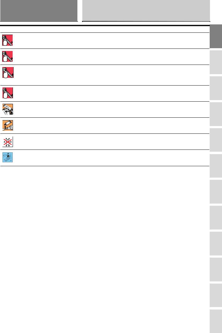
Product specifications
Symbols in the diagram show the type of threadlocker, sealant or lubricant to be used at the points indicated. The table below shows the symbols used and the specifications of the various products.
Symbol |
|
Specifications |
Recommended product |
|
|
Engine oil (for specifications, see Sect. C 2, Fuel, |
SHELL |
|
|
lubricants and other fluids). |
Advance Ultra 4 |
|
|
DOT 4 special hydraulic brake fluid. |
SHELL |
|
|
|
Advance Brake DOT 4 |
|
|
SAE 80-90 gear oil or special products for chains with |
SHELL |
|
|
O-rings. |
Advance Chain or Advance Teflon Chain |
|
|
Anti-freeze (nitride, amine and phosphate free) 30 to 40% |
SHELL |
|
|
solution in water. |
Advance coolant or Glycoshell |
A |
GREASE A |
Multipurpose, medium fibre, lithium grease. |
SHELL Alvania R3 |
B |
GREASE B |
Molybdenum disulphide grease, high mechanical stress |
SHELL |
|
and high temperature resistant. |
Retinax HDX2 |
F |
G |
H |
L |
M |
N |
P |
C |
GREASE C |
Bearing/joint grease for parts subject to prolonged |
SHELL |
|
mechanical stress. Temperature range: -10 to 110 °C. |
Retinax LX2 |
|
D |
GREASE D |
Protective grease, with anti-corrosive and waterproofing |
SHELL |
|
properties. |
Retinax HD2 |
|
E |
GREASE E |
PANKL grease - PLB 05. |
|
F |
GREASE F |
OPTIMOL grease - PASTE WHITE T. |
|
1 |
LOCK 1 |
Low-strength threadlocker. |
Loctite 222 |
LOCK |
|
|
|
2 |
LOCK 2 |
Medium-strength threadlocker, compatible with oil. |
Loctite 243 |
LOCK |
|
|
|
3 |
LOCK 3 |
High-strength threadlocker for threaded parts. |
Loctite 270 |
LOCK |
|
|
|
4 |
LOCK 4 |
Flange sealant resistant to high mechanical stress and |
Loctite 510 |
|
solvents. Resists high temperatures (up to 200 °C) and |
|
|
LOCK |
|
pressures up to 350 Atm; fills gaps up to 0.4 mm. |
|
5 |
LOCK 5 |
Permanent adhesive for smooth or threaded cylindrical |
Loctite 128455 |
|
fasteners on mechanical parts. High resistance to |
|
|
LOCK |
|
mechanical stress and solvents. Temperature range: |
|
|
|
-55 to 175 °C. |
|
6 |
LOCK 6 |
Pipe sealant for pipes and medium to large fasteners. |
Loctite 577 |
|
For water and gases (except oxygen). Maximum filling |
|
|
LOCK |
|
capacity: 0.40 mm diameter clearance. |
|
7 |
LOCK 7 |
Speed bonder for rubber and plastics with elastomer |
Loctite 480 |
|
charged ethylic base. |
|
|
LOCK |
|
|
|
6 |
1098/1098S - M.Y. 2007 - edition 00 |
|
|
section |
|
General |
|
A 2 |
|
|
|
Symbol |
|
Specifications |
Recommended product |
8 |
LOCK 8 |
High-strength retaining compound for threaded parts, |
Loctite 601 |
|
bearings, bushes, splines and keys. Temperature range: |
|
|
LOCK |
|
-55 to 150 °C. |
|
9 |
LOCK 9 |
Medium-strength threadlocker. |
Loctite 401 |
LOCK |
|
|
|
10 |
LOCK 10 |
Product for metal parts to seal and lock cylindrical freely |
Loctite 128443 |
|
sliding or threaded couplings. Resistant to high |
|
|
LOCK |
|
mechanical stress and high temperature, excellent |
|
|
|
resistance to solvents and chemical attack. |
|
11 |
LOCK 11 |
Instant adhesive gel offering tensile/shear strength. |
Loctite 454 gel |
LOCK |
|
|
|
|
|
DUCATI liquid gasket. |
942470014 |
|
|
Exhaust pipe paste. Self-sealing paste, hardens when |
Holts Firegum |
|
|
heated; resists temperatures exceeding 1000 °C. |
|
|
|
Spray used to protect electrical systems. |
SHELL |
|
|
Eliminates moisture and condensation and provides |
Advance Contact Cleaner |
|
|
excellent corrosion resistance. Water repellent. |
|
|
|
Dry lubricant, polymerizing on contact with air |
Molycote D321R |
|
|
|
Molycote M55 Plus |
A |
B |
C |
D |
E |
F |
G |
H |
L |
M |
N |
P |
1098/1098S - M.Y. 2007 - edition 00 |
7 |
|
|

section |
Generalità |
A 3 |
3 - Hazardous Products - Warnings
A
General safety rules
 Carbon monoxide
When a maintenance operation must be performed with the engine running, maker sure that the working area is well-ventilated. B Never run the engine in an enclosed space.
 Warning
C |
D |
E |
F |
G |
H |
L |
M |
N |
P |
Exhaust fumes contain carbon monoxide, which is a poisonous gas that can cause unconsciousness or even death if inhaled.
Run the engine outdoors or, if working indoors, use an exhaust fume extraction system.
Fuel
Always make sure the working area is well ventilated. Keep any sources of ignition, such as cigarettes, open flames or sparks, well away from the area in which fuel is stored.
 Warning
Petrol is highly flammable and can explode under certain conditions. Keep away from children.
Hot parts
 Warning
The engine and exhaust parts become hot when the motorcycle engine is running and will stay hot for some time after the engine has been stopped. Wear heat-resistant gloves before handling these components or allow the engine and exhaust system to cool down before proceeding.
 Warning
The exhaust system might be hot, even after engine is switched off; take special care not to touch exhaust system with any part of your body and do not park the motorcycle next to inflammable material (wood, leaves, etc.).
Used engine oil
 Warning
Prolonged or repeated contact with used engine oil may cause skin cancer. If working with engine oil on a daily basis, make it a rule to wash your hands thoroughly with soap immediately afterwards. Keep away from children.
Brake pad dust
Never clean the brake assemblies using compressed air or a dry brush.
 Warning
Inhalation of asbestos fibres is a proven cause of respiratory illness and cancer.
Brake fluid
 Warning
Avoid spilling brake fluid onto plastic, rubber or painted parts of the motorcycle to avoid the risk of damage. Protect these parts with a clean shop cloth before proceeding to service the motorcycle. Keep away from children.
Coolant
Engine coolant contains ethylene glycol, which may ignite under particular conditions, producing invisible flames. Although the flames from burning ethylene glycol are not visible, they are still capable of causing severe burns.
 Warning
Take care not to spill engine coolant on the exhaust system or engine parts. These parts may be hot and ignite the coolant, which will subsequently burn with invisible flames.
8 |
1098/1098S - M.Y. 2007 - edition 00 |
|
|
section |
Generalità |
A 3 |
Coolant (ethylene glycol) is an irritant and is poisonous when ingested. Keep away from children.
Never remove the radiator cap when the engine is hot. The coolant is under pressure and will cause severe burns if it comes into contact with the skin.
The cooling fan operates automatically: keep hands well clear and make sure your clothing does not snag on the fan.
Battery
 Warning
The battery produces explosive gases; keep it away from any source of ignition such as sparks, flames and cigarettes. When charging the battery, ensure that the working area is properly ventilated.
A |
B |
C |
D |
E |
F |
G |
H |
L |
M |
N |
P |
1098/1098S - M.Y. 2007 - edition 00 |
9 |
|
|

section |
Generalità |
A 3 |
General maintenance indications
A Useful tips
Ducati recommends that you follow the instructions below in order to prevent problems and obtain the best end result: - When diagnosing faults, primary consideration should always be given to what the customer reports about motorcycle
operation since this information can highlight anomalies; your questions to the customer concerning symptoms of the fault should be aimed at clarifying the problem;
B - diagnose the problem systematically and accurately before proceeding further. This manual provides the theoretical background for troubleshooting; this basis must be combined with personal experience and attendance at periodic training courses held by Ducati;
-repair work should be planned carefully in advance to prevent any unnecessary downtime, for example obtaining the required spare parts or preparing the necessary tools, etc.;
-limit the number of operations needed to access the part to be repaired. Note that the disassembly procedures in this manual C describe the most efficient way to reach the part to be repaired.
General advice on repair work
D |
E |
F |
G |
H |
L |
M |
N |
P |
-Always use top quality tools. When lifting the motorcycle, only use devices that comply fully with the relevant European directives.
- When working on the motorcycle, always keep the tools within reach, ideally in the order required, and never put them on the motorcycle or in hard-to-reach or inaccessible places.
- The workplace must be kept clean and tidy at all times.
- Always replace gaskets, seals and split pins with new parts.
- When loosening or tightening nuts and bolts, always start with the largest or start from the centre; tighten nuts and bolts to the specified torque working in a crosswise sequence.
- Always mark any parts and positions which might easily be confused at the time of reassembly.
-Use exclusively Ducati original replacement parts and the recommended brands of lubricants.
-Use special service tools where specified.
-Ducati Technical Bulletins often contain updated versions of the service procedures described in this manual. Check the latest Bulletins for details.
10 |
1098/1098S - M.Y. 2007 - edition 00 |
|
|

A
Information about the model
B |
C |
D |
E |
F |
G |
H |
L |
M |
N |
P |

section |
Information about the model |
B |
A |
B |
C |
D |
E |
F |
G |
H |
L |
M |
N |
P |
1 - Identification data |
3 |
Identification data for the Superbike 1098 |
3 |
2 |
1098/1098S - M.Y. 2007 - edition 00 |
|
|
section |
Information about the model |
B 1 |
1 - Identification data
Identification data for the Superbike 1098
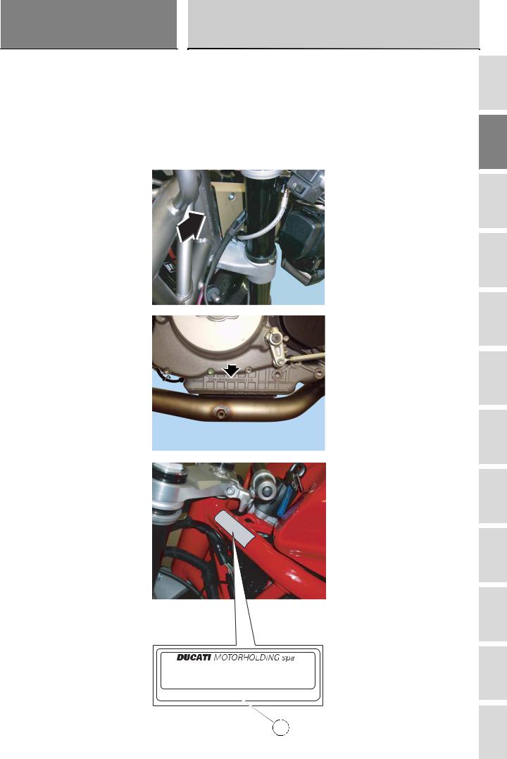
Each Ducati motorcycle has two identification numbers - the frame number and the engine number - and an EC nameplate (A)
(not present on the US version).
 Notes
Notes
Please quote these numbers, which identify the motorcycle model, when ordering spare parts.
e?*?? / ?? * ???? * *ZDM??????????????*
??dB(A) - ???? min-1
??? ? ??? ??
 A
A
A |
B |
C |
D |
E |
F |
G |
H |
L |
M |
N |
P |
1098/1098S - M.Y. 2007 - edition 00 |
3 |
|
|
|
section |
|
|
B 1 |
|
|
Data stamped on the frame |
|
A |
Europe version |
|
1 |
Manufacturer: Ducati Motor Holding |
|
|
2 |
Type, same on all 1098 models. |
|
3 |
Variant |
|
4 |
Version |
B |
5 |
Year of manufacture (7=2007) |
6 |
Manufacturing facility |
|
|
7 |
Progressive serial No. |
C |
D
E Data stamped on the frame
US version
|
1 |
Manufacturer: Ducati Motor Holding |
|
2 |
Motorcycle type |
F |
3 |
Variant – Numeric or X (Check digit) |
4 |
Model year (7=2007) |
|
5 |
Manufacturing facility |
|
|
6 |
Progressive serial No. |
G |
H |
L |
M |
N |
P |
Information about the model
Data stamped on the frame
Europe version
1 |
2 |
3 |
4 |
5 |
6 |
7 |
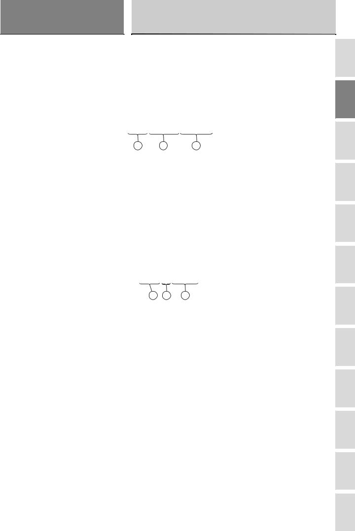
ZDM H7 00 AA X B 000001
Data stamped on the frame
US version
1 |
2 |
3 |
4 |
5 |
6 |
ZDM 1 X B EW X B 000000
Variant - numeric from 0 to 9 or X (Check digit)
4 |
1098/1098S - M.Y. 2007 - edition 00 |
|
|
section |
Information about the model |
B 1 |
Data stamped on engine
Europe version
1Manufacturer: Ducati Motor Holding
2Engine type
3Progressive production No.
Data stamped on engine
Europe version
ZDM 1098W4*000002*
1 |
2 |
3 |
Data stamped on engine
US version
1Engine type
2Model year
3Progressive production No.
Data stamped on engine
US version
XBE X 000001
1 2 3
A |
B |
C |
D |
E |
F |
G |
H |
L |
M |
N |
P |
1098/1098S - M.Y. 2007 - edition 00 |
5 |
|
|

A
Technical data
B |
C |
D |
E |
F |
G |
H |
L |
M |
N |
P |

section |
Technical data |
C |
A |
B |
C |
D |
E |
F |
G |
H |
L |
M |
N |
P |
1.1 - Technical specifications |
3 |
General |
3 |
Colours |
4 |
Transmission |
4 |
Timing system/valves |
5 |
Crankshaft |
5 |
Cylinder/Piston |
5 |
Gearbox |
6 |
Cooling system |
6 |
Front wheel |
6 |
Front suspension (1098) |
6 |
Front suspension (1098S) |
7 |
Rear wheel |
7 |
Rear suspension (1098) |
7 |
Rear suspension (1098S) |
7 |
Hydraulic brakes |
8 |
Charging system/alternator |
8 |
Injection - ignition system |
8 |
Fuel system |
8 |
Lights/instrument panel |
9 |
1.2 - Dimensions |
10 |
2 - Fuel, lubricants and other fluids |
11 |
3 - Torque settings |
12 |
Frame torque settings |
12 |
Engine torque settings |
13 |
4 - Service tools |
16 |
Special tools for the engine |
16 |
Special tools for the frame |
22 |
2 |
1098/1098S - M.Y. 2007 - edition 00 |
|
|
 Loading...