

Druck DPI 822 Operating Manual
GE Infrastructure
Sensing
Druck DPI 821/822
Thermocouple calibrator and
Thermocouple loop calibrator
User manual - K346
A1
B1
10
A2
A3
1
A2
9
A3
8
2
3
4
7
6
5
11
B1
12
DPI 822
1513
14
17182619 2716
20
21
22
23
K346 Issue 2
24
25
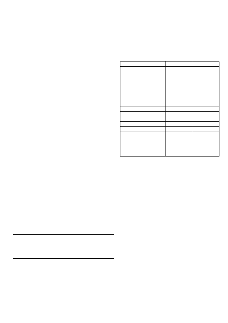
Table of Contents
Introduction ......................................................................... 1
Safety ..................................................................................... 1
Safety - Marks and symbols on the instrument ............... 2
To start .................................................................................. 2
To start - Location of items ........................................................ 2
To start - Items on the display .................................................. 2
To start - Prepare the instrument ........................................... 2
To start - Power on or off ............................................................ 3
To start - Set up the basic operation ..................................... 3
To start - Select a task (Measure and/or simulate) ......... 3
To start - Set up the settings ..................................................... 4
To start - Edit functions ................................................................ 5
Operation .............................................................................. 6
Operation - Thermocouple connections .............................. 6
Operation - Communications port connections .............. 6
Operation - Measure thermocouple values ....................... 6
Operation - Change the output values ................................. 6
Operation - Simulate thermocouple values ....................... 7
Operation - Transmitter calibration ....................................... 7
Operation - mA measurements ............................................... 8
Operation - Switch test ................................................................ 8
Operation - UPM Pressure measurements ......................... 9
Operation - Error indications ..................................................... 9
Maintenance ..................................................................... 10
Maintenance – Clean the unit ................................................ 10
Maintenance – Replace the batteries ................................ 10
Calibration ......................................................................... 10
Calibration - Before you start ................................................. 10
Calibration - Procedures (mV input or output) ............... 10
Calibration - Procedures (CJ input) ...................................... 11
Calibration - Procedures (mA input) .................................... 11
Calibration - Procedures (IDOS UMM) ................................. 11
Specification data ............................................................ 11
Specification - General .............................................................. 11
Specification - Temperature ranges ................................... 12
Specification - mV range .......................................................... 12
Specification - Electrical connectors (A2) ......................... 12
Customer service ............................................... Back cover
© 2005 General Electric Company. All rights reserved.
Trademarks
All product names are trademarks of their respective companies.
Introduction
The DPI 821 Thermocouple Calibrator and DPI 822
Thermocouple Loop Calibrator are part of the Druck
DPI 800 series of hand held instruments.
The DPI 800 series uses Intelligent Digital Output Sensor
(IDOS) technology to give instant plug and play
functionality with a range of Universal Measurement
Modules (UMM). Example: the Universal Pressure Module
(UPM).
The DPI 821/822 include these functions:
Function DPI 821 DPI 822
Measure/simulate
thermocouple temperature
or mV
Cold Junction (CJ)
compensation
Step/Ramp functions Automatic/Manual
Communications port IDOS or RS232
Language selection Yes
Measure pressure/Leak test ** External IDOS UPM
** Snapshot Up to 1000 displays with a
Measure mA No 0 - 55 mA
HART® resistor No Yes
V dc output No 24 V
Switch test No Yes
Other functions Hold, Maximum/Minimum/Average,
Filter, Tare, Scaled values, Backlight,
Alarm
* Refer to “Specification data”.
** Optional item
* Yes
Automatic/Manual
date/time stamp
Safety
Before you use the instrument, make sure that you read
and understand all the related data. This includes: all local
safety procedures, the instructions for the UMM (if
applicable), and this publication.
WARNING
• It is dangerous to ignore the specified limits for the
instrument or to use the instrument when it is not in
its normal condition. Use the applicable protection
and obey all safety precautions.
• Do not use the instrument in loca tions with explosive
gas, vapor or dust. There is a risk of an explosion.
Continued
[EN] English - 1K346 Issue 2
Safety (Continued)
• To prevent electrical shocks or damage to the
instrument, do not connect more than 30V between
the terminals, or between the terminals and the
ground (earth).
• UPM only. To prevent a dangerous release of
pressure, isolate and bleed the system before you
disconnect a pressure connection.
Before you start an operation or procedure in this
publication, make sure that you have the necessary skills
(if necessary, with qualifications from an approved
training establishment). Follow good engineering practice
at all times.
Safety - Marks and symbols on the instrument
Complies with European
Union directives
Read the manual Battery
Ground (Earth)
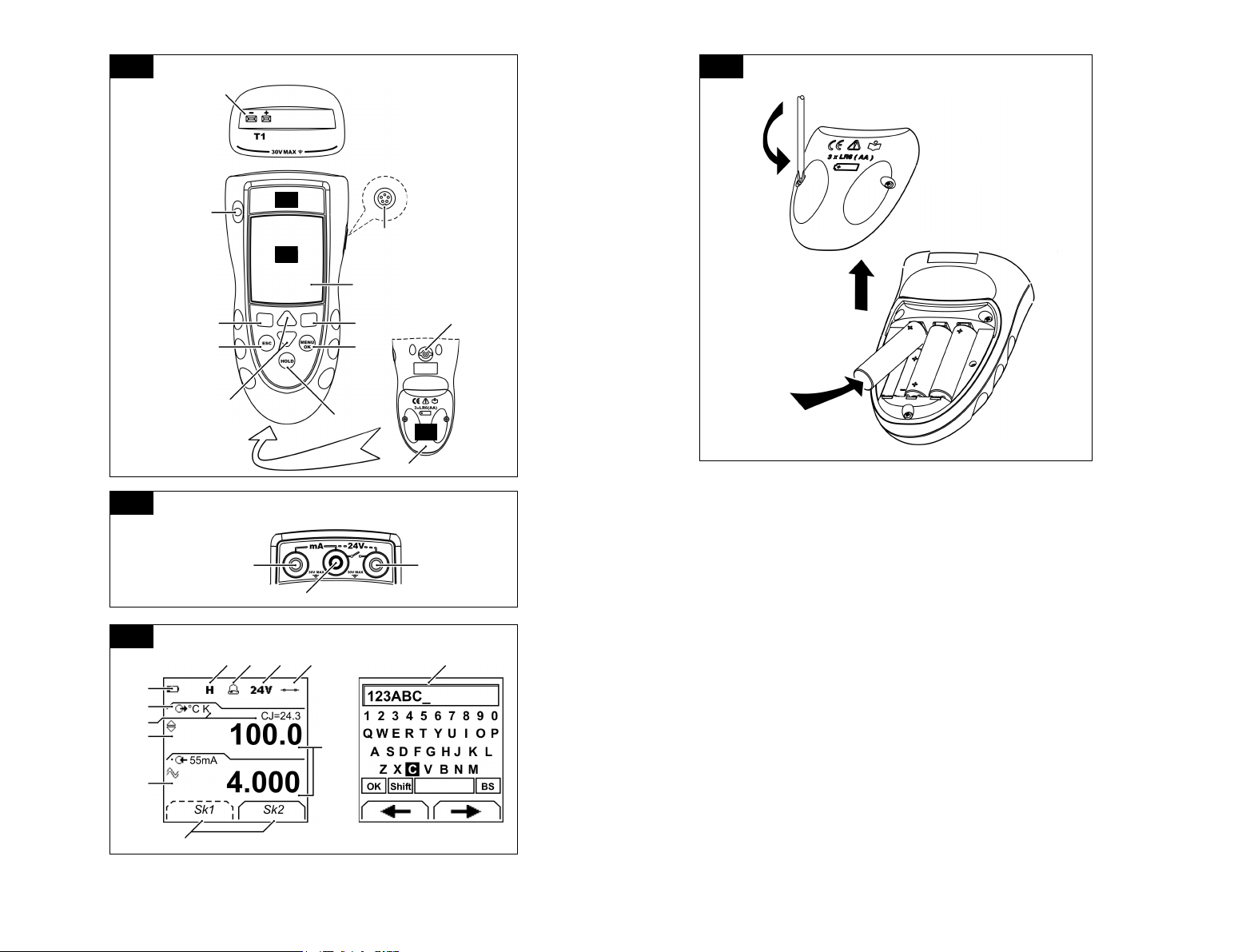
T1 Identifies the thermocouple connector
Warning - refer to the
manual
ON/OFF
To start
To start - Location of items …
Item Description
1. ❍ On or off button.
2.
3.
4.
5.
6.
7.
8. Display. Refer to A3
9.
10. Thermocouple connector: Refer to “Operation”.
11. Connection point for some of the optional
12. Battery compartment. Refer to B1.
13., 14., 15. DPI 822 only. Terminals to measure current, to supply
Left-hand soft-key. Selects the function above it on
■ ■
the display (Item 25). Example: Edit
Moves back one menu level.
ESC
Leaves a menu option.
Cancels the changes to a value.
Increases or decreases a value.
▲
▼
Highlights a different item.
Holds the data on the display. To continue, press the
HOLD
HOLD button ag ain.
Shows the Select Task menu.
MENU
Selects or accepts an item or value.
OK
Selects [✓] or cancels [ ] a selection.
Right-hand soft-key. Selects the function above it on
■ ■
the display (Item 25). Example: Settings
Communications port. Use to connect a Universal
SENSOR
/ PC
Measurement Module (UMM) or a RS232 cable.
accessories. Refer to the datasheet.
24V source, and to do switch tests.
A1 A2
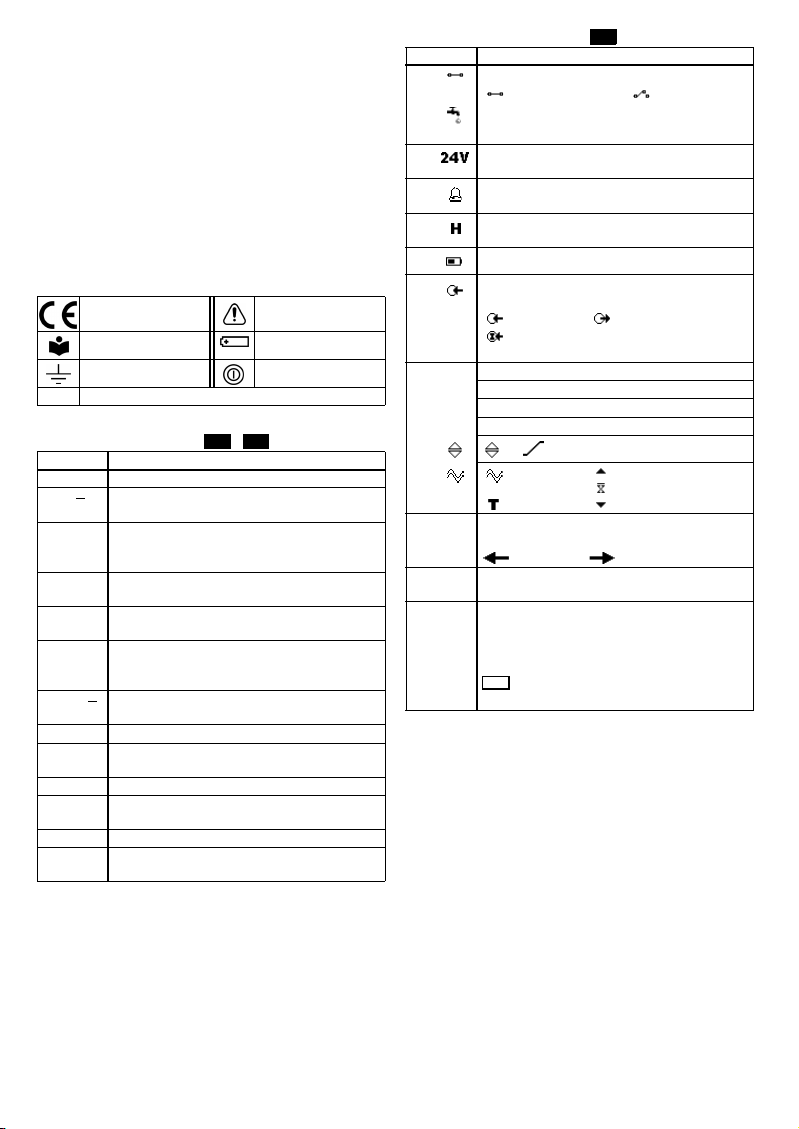
To start - Items on the display
Item Description
16. DPI 822 only. Task indication for the switch test.
17. DPI 822 only. The loop power supply is on.
18. The measured value satisfies one of the alarm
19. The data on the display is on hold. To continue, press
20.
21. Identifies the type of data and the measurement
22. ... 24. The settings applied to the input or output.
22. °C The units or a specified scale (x:y ) - (Table 4/5).
K The thermocouple type (K, J, T ... ) - (Table 4/5).
CJ= ... The cold junction temperature (Table 1)
23.
24. = Filter
25. A soft-key function. To select an available function,
26. The measured value or values applicable to the task
27. The Edit display to set up text labels ( ≤ 6 characters):
= switch closed
UPM only. Task indication for the leak test.
Refer to: Select Task (Table 2/3)
Refer to: Select Task (Table 2/3)
conditions. Refer to: Settings (Table 4)
the HOLD button again.
Shows the battery level: 0 ... 100%.
range.
= Input = Output
= IDOS input
Refer to: Select Task (Table 2/3)
, ... ,
= Tare
press the soft-key below it. Example:
= Move left = Move right
selection.
x:y Scaling (Table 4).
OK = Accept the new text label
Shift = Change the keys: 1 23ABC or -_+abc
= Add a space
BS = Back space (Delete character)
A3
= switch open
= Output operation (Table 5)
= Maximum
= Average
= Minimum
(Table 4)
To start - Prepare the instrument
Before you use the instrument for the first time:
• Make sure that there is no damage to the instrument,
and that there are no missing items.
• Remove the plastic film that protects the display. Use
the tag (◗ ) in the top right-hand corner.
• Install the batteries (refer to B1). Then re-attach the
cover.
2 - [EN] English K346 Issue 2

To start - Power on or off
To turn the instrument on or off, press ❍ (A 1 - item [1]). The
instrument does a self test and then shows the applicable
data.
When the pow er is off, the last set of con figuration options
stays in memory. Refer to “Maintenance”.
To start - Set up the basic operation
Use the Set Up menu to set up the basic operation of the
instrument.
Menu:
1
Select Task
(Table 2) (Table 1) [✓]/[ ]
23
▲
▼
Menu:
Set Up
45
▲
▼
If there is additional data for a menu option, select
Settings (■■
) to see the values that are set up. If
necessary, adjust the values.
Table 1: (Part of table) Menu options - Set Up
Options
(If applicable)
Descript ion
DPI 822 only. To add a series resistor into the mA
circuit. You can then use this instrument together
with a HAR T® communic ator to set up and
calibrate HART® devices.
... Scale To select the applicable international temperature
scale: IPTS 68 or ITS 90.
CJ ... To select the type of cold junction (CJ)
compensation.
Automatic : The instrument monitors the CJ
temperature and applies the necessary CJ
compensation.
Manual: Measure the CJ temperature and set the
applicable value. The instrum ent uses this valu e to
apply the necessary CJ compensation.
Additional data (Manual): Select Settings (■ ■)
To select and set up the backlight facility + timer.
Additional data: Select Settings (■ ■)
To select and set up the power off facility + timer.
Additional data: Select Settings (■ ■)
To show the battery level (%).
To set the display contrast (%).
▲ Increases %, ▼ decreases %
Table 1: (Part of table) Menu options - Set Up
Options
(If applicable)
Description
To set the time + date. The calibration facility uses
the date to give service and calibration messages.
To set the language option.
To calibrate the instrument.
Additional data: Refer to “Calibration”.
To select and show the applicable status data.
(Software Build, Cali bration Due date, Serial
Number, IDOS Information).
To start - Select a task (Measure and/or simulate)
When the instrument is set up (Table 1), use the Select Task
menu to select the applicable task.
1
Menu:
Select Tas k
(Table 2/3)
23
▲
▼
Display:
T1 output
Sk1 = Edit
Sk2 = Settings
In Table 2/3, IDOS is a Universal Measurement Module
(UMM). If you attach a UMM to the communications port
(A1 - item [9]), the Select Task menu shows the applicable
IDOS options.
Table 2: Menu options - Select Task
Options
(If applicable)
IDOS UMM only. An IDOS measurement task.
UPM only. A leak test.
Description
T1 ormVAn input measurement task:
T1 - Measure thermocouple temperature OR
mV - Measure thermocouple mV.
T1 ormVAn output task:
T1 - Simulate thermocouple temperature OR
mV - Simulate thermocouple mV.
mA DPI 822 only. A mA measurement task.
mA(24V) DPI 822 only. A mA measurement task + the loop
power supply is on .
DPI 822 only. A switch test.
To set up the way the instrument works.
Additional data: Refer to: Set Up (Table 1) .
Table 3 shows all the one and two function operations that
are available. If you attach a UMM, you can only use the
options that include IDOS.
[EN] English - 3K346 Issue 2
 Loading...