

Druck DPI 705 Operating Manual

GE
Sensing & Inspection Technologies
Druck DPI 705/DPI 705 IS Series
Digital Pressure Indicator
User Manual K0214
English 1 - 6
Français 7 - 12
Deutsch 13 - 18
Italiano 19 - 24
Español 25 - 30
Português 31 - 36
g
©The General Electric Company. All rights reserved
Approved Service Agents
For the list of service centres visit our web site:
www.gesensinginspection.com
Symbols
This equipment meets the requirements of all relevant European
safety directives. The equipment carries the CE mark.
This symbol, on the instrument, indicates that the user should refer
to the user manual.
Do not dispose of this product as household waste. Use an
approved organisation that collects and/or recycles waste electrical
and electronic equipment. For more information:
Contact us at www.gesensinginspection.com
Centres de réparation agréés
Pour obtenir la liste des centres de réparation agréés, consultez notre site Web à l’adresse
suivante :
www.gesensinginspection.com
Symboles
Cet appareil satisfait aux exigences de toutes les directives
européennes de sécurité applicables. Cet appareil porte le
marquage CE.
Ce symbole, sur l’instrument, indique que l’util isateur doit consulter
le manuel d’utilisation.
Ne jetez pas ce produit avec vos ordures ménagères. Faites appel à
un organisme agréé de collecte et/ou de recyclage des déchets
électriques et électroniques. Pour plus d’informations :
Contactez-nous via le site Web www.gesensinginspection.com
K0214 Issue No. 5
Autorisierte Servicevertretungen
Eine Liste der Servicezentren finden Sie auf unserer Webseite:
www.gesensinginspection.com
Symbole
Dieses Gerät erfüllt die Anforderungen der entsprechenden
europäischen Sicherheitsrichtlinien. Das Gerät ist mit dem CEPrüfzeichen versehen.
Bei diesem Symbol auf dem Gerät sollte der Anwender im
Handbuch nachschlagen.
Dieses Gerät darf nicht im Haushaltsmüll entsorgt werden. Geben
Sie das Gerät bei einer autorisierten Stelle ab, die alte Elektro- und
Elektronikgeräte sammelt und/oder wiederverwertet . Weitere
Informationen:
Kontaktieren Sie uns unter www.gesensinginspection.com.
Centri di assistenza autorizzati
Per l’elenco dei centri di assistenza consultare il sito:
www.gesensinginspection.com
Simboli
Questa apparecchiatura risponde ai requisiti di sicurezza imposti da
tutte le direttive europee applicabili in materia. L’apparecchiatura
riporta il marchio CE.
Questo simbolo applicato allo strumento suggerisce di consultare il
manuale utente.
K0214 Issue No. 5
Non smaltire il prodotto nei rifiuti domestici. Rivolgersi ad enti
autorizzati alla raccolta e/o al riciclaggio di apparecchiature
elettriche ed elettroniche dismesse. Per ulteriori informazioni
consultare la pagina:
www.gesensinginspection.com

Agentes de servicio técnico autorizados
Si desea consultar la lista de centros de servicio técnico, visite nuestro sitio web:
www.gesensinginspection.com
Símbolos
Este equipo cumple los requisitos de todas las directivas europeas
de seguridad pertinentes. El equipo posee la marca CE.
Este símbolo, en el instrumento, indica que el usuario debe
consultar el manual del usuario.
No deseche este producto como residuo doméstico. Hágalo
mediante una organización autorizada que recoja o recicle residuos
eléctricos y equipos electrónicos. Para obtener más información:
Póngase en contacto con nosotros en
www.gesensinginspection.com
Agentes de manutenção aprovados
Para obter a lista de centros de serviço, visite nosso site:
www.gesensinginspection.com
Símbolos
Este equipamento atende aos requisitos de todas as diretivas de
segurança européias relevantes. O equipamento possui a marca
CE.
Este símbolo, no instrumento, indica que o usuário deve consultar o
manual do usuário.
Não jogue fora este produto como se fosse um resíduo doméstico.
Use uma organização aprovada para coletar e/ou reciclar
equipamentos elétricos e eletrônicos residuais. Para obter mais
informações:
Entre em contato conosco através do site
www.gesensinginspection.com
K0214 Issue No. 5

K0214 Issue No. 5
intentionally left blank
DPI 705 Series Digital Pressure Indicator
Introduction
The Druck DPI 705 pressure indicator uses a micro-machined silicon transducer to
produce a pressure reading in units of pressure measurement. These user instructions
include the operations for all DPI 705 Pressure Indicators, safety instructions and the
requirements for intrinsically safe instruments.
Specification
Accuracy:
Combined non-linearity, hysteresis and repeatability ............................... ±0.1% full-scale (FS)
Temperature effects: Span ............................................................................................. ±0.02%rdg/°C
Operating range ........................................................................ -10°C t o 50°C (15°F to 120°F)
Storage range ............................................................................... -20°C t o 60°C (-5°F to 140°F)
Maximum safe working pressure ...................................................................................... 2 x full-scale
Pressure connector ............................................................................. 6 mm o/d and 4 mm i/d hose,
........................................................................................................ G1/8 or 1/8"NPT female thread
Maximum torque ........................................................................................................ 2.259 Nm (20 lb. in)
Environmental ...................................................................................................................... IP54 (NEMA 12)
Electrical safety ........................................................................................... BS EN 61010 as applicable
Electromagnetic compatibility .................................................................. EN50081-1 (emissions)
Electrical Power Supply for non-certified units ........................................... 3 x 1.5 V alkaline size AA
Safety
Zero .............................. <= 1 bar ±0.05%FS/°C (absolute ranges only)
.......................................... > 1 bar ±0.02%FS/°C (absolute ranges only)
.................................................................... EN50082-2 (immunity)
This symbol, on the pressure indicator, indicates that the user should
refer to the user guide or manual.
English
Pressure
Batteries
Cleaning
Calibration
Do not apply pressure greater than the maximum safe working pressure.
Do not apply pressure greater than 1.1 bar (15.95 psi) absolute to the -ve
pressure port of differential pressure indicators.
Remove batteries from the pressure indicator immediately when
discharged and before storage.
Dispose of batteries in accordance with local regulations and battery
manufacturers' instructions.
When storing and transporting batteries make sure they cannot be short
circuited.
Clean the pressure indicator with a damp cloth.
Refer to the Calibration and Configuration Instructions.
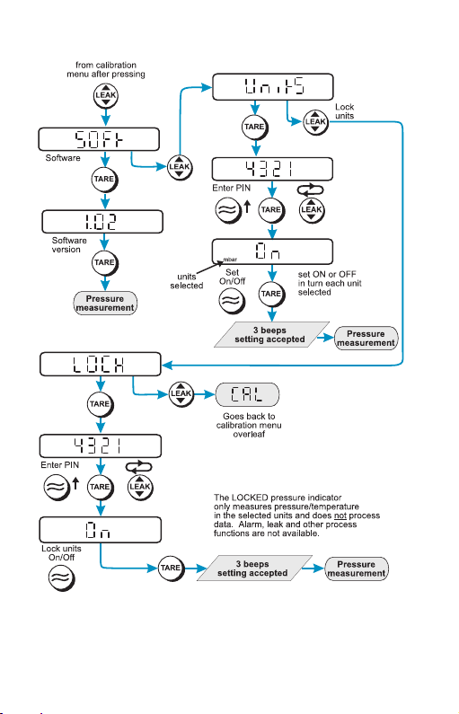
Software Version
for pressure indicators with software version 1.02 onwards. Further changes
to the pressure indicator's software may require a change to the operating
instructions and an issue number change of the manual.
This manual contains operating instructions
K0214 Issue No. 51
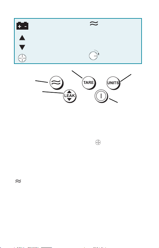
Display Symbols
Batteries are low, replace
observing polarity shown on case
Displayed reading - maximum value
Displayed reading - minimum value
Displayed reading - leakage (per
minute)
Switch Tare on or off (changes the
display reading to zero)
Switch filter
on or off
View maximum,
minimum or perform leak
test (max/min is reset at
switch on)
Operation
TIME OUT
If a key is not pressed within 10 minutes then the instrument times out and switches
off. To disable this automatic time out, hold the LEAK key when switching on the pressure
indicator.
LEAK TEST
To perform a leak test, press the LEAK key 3 times. The symbol flashes on the
display with the number 60. To start the leak test press the LEAK key again. The
instrument counts down 60 seconds displaying the leakage at the end of the 60 second
period. Press the LEAK key at any time during the leak test to quit and return to normal
measurement.
ZERO
A zero should be performed on gauge and differential instruments before measuring
pressure. To perform a zero: Open all pressure ports to atmospheric pressure. Press
the and TARE keys together, the display briefly shows ZErO and the instrument
calculates a new zero.
Note: A zero can only be performed on absolute pressure indicators if a vacuum
is first applied to the pressure port.
Filter applied
(10 reading rolling average)
Tare applied
TARE
A
Alarm - pressure value
(flashing)
more than alarm setting
Leak test in progress
(count down)
Change units (1 of 16
pressure units, °C or °F)
Switch
on or off
Alarm
A single alarm can be set to operate when the displayed pressure value rises above the
alarm setting. The alarm causes the display to flash and a beeper to sound for one
minute. Pressing TARE and UNITS keys together displays the alarm value, pressing the
FILTER key increases the alarm value, pressing the UNITS key decreases the alarm
value. When the display shows the required alarm value, press the TARE key to set the
alarm.
K0214 Issue No. 5
2
Intrinsically Safe Pressure Indicators
Introduction
These instructions detail the requirements for using the DPI 705 Intrinsically Safe
Pressure Indicator in a hazardous area. Read the whole publication before starting.
Special note
This instrument has been certified by ATEX and CSA. The batteries certfiied for use by each
certifying body are different. It is the user's responsibility to use the correct batteries.
Installation Requirements in Hazardous Areas
ATEX Certification
Markings:
Ex ia IIC T4 Ga (-10°C
BAS02ATEX1194 ............................................... cer tificate number
DPI 705 IS .......................................................... specific apparatus type
Pressure range in mbar or psi ....................... full-scale pressure rating
Druck LTD, Groby, LE6 0FH, UK ..................... manufacturer's name and address
SN*******/YY-MM ............................................ serial number and date of
Requirements and Conditions
Batteries
WARNING: ONLY REPLACE BATTERIES IN A SAFE AREA
• Power supply only use 3 x LR6 (AA), Duracell PROCELL, Duracell PLUS, ENERGIZER
ULTIMATE or GP SUPERALKALINE.
Installation
WARNING:
• Installation should be carried out by qual ified plant installation technicians in
compliance with the latest issue of EN 60079-14.
• Provide additional protection for indicators that may be damaged in service.
Declaration Requirements
The DPI 705 IS is designed and manufactured to meet the essential health and safety
requirements not covered by EC Type Examination Certificate BAS02ATEX1194 when
installed as detailed above.
This intrinsically safe instrument is designed and manufactured to protect against other
hazards as defined in paragraph 1.2.7 of Annex II of the ATEX Directive 94/9/EC.
≤≤
≤ ≤
≤ Ta
≤ +50°C) .............. hazardous location markings
≤≤
≤ ≤
II 1 G
1180
........................... equipment group and category
........................... CE mark
manufacture, year-month
DO
NOT USE TOOLS ON THE PRESSURE INDICATOR THAT MIGHT CAUSE INCENDIVE
SPARKS
-
THIS CAN CAUSE AN EXPLOSION.
English
K0214 Issue No. 53

CSA Certification
Markings:
Ex ia IIC T4, Class 1, Zone 0 and Class 1, Div.1
Groups A, B, C & D ..................................................... hazardous location designation
1999 LR110032-3 ....................................................... certificate reference
Amb Temp -10°C to +50°C ........................................ ambient temperature range
..................................... CSA monogram
DPI 705 IS .................................................................... specific apparatus type
Pressure range in mbar or psi ................................. full-scale pressure rating
Druck LTD, Groby, LE6 0FH, UK ............................... manufacturer's name and address
SN*******/YY-MM ...................................................... serial number and date of
manufacture, year-month
Requirements and Conditions
Batteries
WARNING: ONLY REPLACE BATTERIES IN A SAFE AREA
• Power supply use only 3 x LR6 (AA) made by Eveready Energizer LR6, Varta 4006
or Duracell Procell MN1500.
Installation
WARNING:
• Installation should be carried out by qualif ied plant installation technicians in
• Provide additional protection for indicators that may be damaged in service.
DO
NOT USE TOOLS ON THE PRESSURE INDICATOR THAT MIGHT CAUSE INCENDIVE
SPARKS
-
THIS CAN CAUSE AN EXPLOSION.
compliance with the latest issue of Canadian Electrical Code (CEC).
Maintenance
Note: The following applies to all instruments of the DPI 705 Series.
• Return the instrument to the factory for any repairs, it cannot be repaired on-site.
• To keep the DPI 705 accurate to 0.1% full-scale a calibration check should be
carried out once per year.
Cleaning
• Clean the instrument case with a moist, lint-free cloth and weak detergent.
K0214 Issue No. 5
4
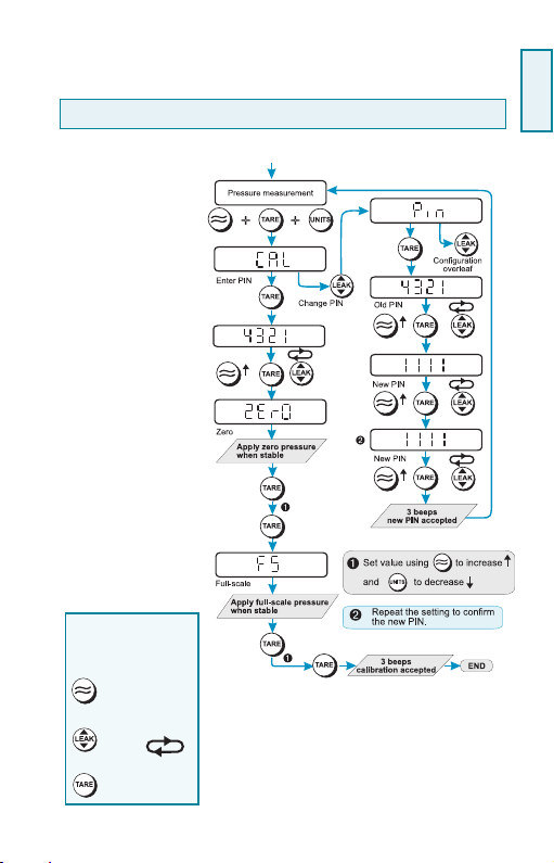
Calibration Instructions
WARNING: CALIBRATE DPI 705 IS INSTRUMENTS IN A SAFE AREA.
The instrument performs a two-point compensation at ZErO and FS (full-scale.)
Preparation
1.
Connect the instrument to
a pressure source
that has an accuracy
three times better than the
instrument.
Recommended:Druck DPI 610 or DPI 610
IS Portable Calibrator.
2.
Switch on the instrument
and select the units of
pressure measurement
required for calibration.
Procedure
1.
Press all three keys
together to enter the
CAL menu and proceed as
shown:
Changing the PIN
Each digit can be changed
in turn.
Pressing:
increases the value
of the digit.
steps to next digit,
left
to right.
enters the PIN
English
K0214 Issue No. 55
K0214 Issue No. 5
6
Indicateur de pression de la série DPI 705
Introduction
L’indicateur de pression Druck DPI 705 utilise un capteur silicone micro-usiné pour
produire une mesure de pression en unités de mesure de pression. Cette notice
utilisateur décrit le fonctionnement de tous les indicateurs de pression DPI 705, les
consignes de sécurité et les exigences de sécurité intrinsèque des instruments.
Spécification
Précision :
Non linéarité hystérésis répétabilité ............................................................ ± 0,1 % Pleine échelle
Effets thermiques: Sensibilité ............................................................................ ± 0,02 % lect/°C
Température de fonctionnement .............................................................................. -10 à 50°C
Température de stockage .............................................................................................-20 à 60°C
Pression maximum de sécurité en service .......................................................... 2 × pleine échelle
Raccord de pression ...................................................................... Tuyau de 6 mm d/e et 4 mm d/i,
................................................................................... Filetage G1/8 femelle ou 1/8 NPT femelle
Couple maximum .......................................................................................................................... 2,259 Nm
Protection de l’environnement ..................................................................................... IP54 (NEMA 12)
Normes de sécurité concernant l'électricité ........................................ BS EN 61010, s'il y a lieu.
Compatibilité électromagnétique ................................................................ EN50081-1 (émissions)
..................................................................................................................... EN50082-2 (insensibilité)
Alimentation électrique .................................................................... 3 batterie alcalines AA de 1,5 V
Attention
Pression
Batteries
Entretien
Calibration
Zéro ......... < = 1 bar ± 0,05 % FS/°C (plages absolues seulement)
........................... > 1 bar± 0,02 % FS/°C (plages absolues seulement)
Quand ce symbole parait sur l'indicateur de pression, se reporter
au Mode d'emploi ou à la Notice d'utilisation.
Ne pas appliquer de pression plus forte que la pression de
service surpression admissible.
Ne pas appliquer de pression supérieure à 1,1 bar (absolue) sur
le port de pression -ve des indicateurs de pression différentielle.
Enlever immédiatement les batteries de l’indicateur de pression
dès qu’elles sont déchargées et avant de les stocker.
Disposer des batteries selon les règlementations régionales en
vigueur et les consignes du fabricant.
Quand vous stockez et transportez les batteries, veillez à ce
qu’elles ne se court-circuitent pas.
Nettoyez l’indicateur de pression à l’aide d’un chiffon humide.
Français
Version Logiciel Ce manuel renferme les consignes relatives au
fonctionnement et est destiné aux indicateurs de pression dontles logiciels commencent à
partir de la version 1.02. Les changements éventuels apportés au logiciel de l’indicateur de
pression sont susceptibles de modifier les consignes de fonctionnement de même que le
numéro de l’édition de cette notice.
K0214 Issue No. 57
 Loading...