

Druck DPI 620 Genii Operating Manual
User Manual Druck DPI620 Genii
GE Measurement & Control
Druck DPI 620 Genii
Advanced Modular Calibrator
K0541
© 2014 General Electric Company. All Rights Reserved. Specifications are
subject to change without notice. GE is a registered trademark of General
Electric Company. Other company or product names mentioned in this
document may be trademarks or registered trademarks of their respective
companies, which are not affiliated with GE

User Manual Druck DPI620 Genii
Contents
1 Overview ................................................................................................................... 9
1.1 Equipment in the Box ........................................................................................ 9
1.2 Optional Items ................................................................................................ 10
1.3 Observance of the User Manual .................................................................... 10
1.4 General Safety Precautions ............................................................................. 11
1.5 General Warnings ........................................................................................... 12
1.6 Electrical warnings .......................................................................................... 13
1.7 Pressure Warnings .......................................................................................... 16
1.8 Preparing the Instrument ............................................................................... 17
1.9 Install the Battery ............................................................................................ 17
1.10 Charge the Battery .......................................................................................... 19
Battery Charging Times ........................................................................... 19 1.10.1
1.11 Basic Modes .................................................................................................... 20
Power On ................................................................................................ 20 1.11.1
Power Off ................................................................................................ 20 1.11.2
Power up from Standby Mode ................................................................ 21 1.11.3
1.12 Druck DPI 620 Genii, Modes ........................................................................... 22
Dashboard navigation ............................................................................. 23 1.12.1
Set Date, Time and Language ................................................................. 24 1.12.2
Themes .................................................................................................... 24 1.12.3
Druck DPI 620 Genii Manual ................................................................... 24 1.12.4
Alarm Status ............................................................................................ 24 1.12.5
................................................................................................................................ 24
28 April 2014 K0541 issue 2 Page 2 of 200

User Manual Druck DPI620 Genii
To View Alarms select: ................................................................................................ 25
1.13 Software and Firmware Upgrades .................................................................. 26
Viewing Software Revision ...................................................................... 26 1.13.1
Upgrading the Software .......................................................................... 26 1.13.2
1.14 Maintenance ................................................................................................... 31
Cleaning ................................................................................................... 31 1.14.1
1.15 Instrument Return .......................................................................................... 32
Returned Material Procedure for USA .................................................... 32 1.15.1
Returned Goods Procedure for Europe .................................................. 33 1.15.2
Instrument Disposal in the European Union ........................................... 34 1.15.3
1.16 Packaging for Storage or Transportation ........................................................ 35
Environment............................................................................................ 35 1.16.1
1.17 Marks and Symbols ......................................................................................... 35
2
Electrical
Operations
............................................................................................... 36
2.1 Basic Calibrator Operation .............................................................................. 36
Saving Tasks ............................................................................................ 37 2.1.1
Electrical Tasks ........................................................................................ 38 2.1.2
Favourites ................................................................................................ 40 2.1.3
Custom Task ............................................................................................ 41 2.1.4
2.2 Set the Function Utility Options ...................................................................... 44
Max/Min ................................................................................................. 44 2.2.1
Switch Test .............................................................................................. 45 2.2.2
Relief Valve.............................................................................................. 46 2.2.3
2.3 Measurement Display Options ....................................................................... 48
2.4 Example Procedure: Measure or Source Current ........................................... 50
2.5 Example Procedure: Measure DC Voltage ...................................................... 51
28 April 2014 K0541 issue 2 Page 3 of 200

User Manual Druck DPI620 Genii
2.6 Example Procedure: Measure AC Voltage (CH1), 0 to 20 Vrms Only ............. 52
2.7 Example Procedure: Measure AC Voltage (CH1) with the AC Probe .............. 53
2.8 Example Procedure: Source DC Voltage (CH1) ............................................... 54
2.9 Example Procedure: Measure or Source Current with 24V Loop ................... 55
2.10
Example Procedure:
Measure or Source Frequency
Signals
........................... 57
2.11 Example Procedure: Measure/Simulate a Resistance Temperature Detector
(RTD) 59
2.12 Example Procedure: Measure or Simulate a Thermocouple (TC) ................... 61
2.13 Example Procedure: Switch Test ..................................................................... 63
2.14 Measure Pressure: IDOS Option ..................................................................... 66
IDOS Option Assembly Instructions ........................................................ 67 2.14.1
IDOS Function Procedures ...................................................................... 68 2.14.2
2.15 Error Indications .............................................................................................. 69
3 Pressure Indicator Operation (MC620) ................................................................... 70
3.1 Parts and Assembly ......................................................................................... 71
Assembly Instructions ............................................................................. 73 3.1.1
3.2 Pressure Connections ..................................................................................... 74
Procedure (Attaching External Equipment) ............................................ 74 3.2.1
3.3 Procedure Overview ....................................................................................... 76
3.4 Set up a Leak Test ........................................................................................... 79
3.5 Set the Pressure Module to Zero .................................................................... 81
3.6 Error Indications .............................................................................................. 82
4 Data Logging Operation .......................................................................................... 83
4.1
Set-up
.............................................................................................................. 85
4.2 Operation ........................................................................................................ 87
4.3 File Review ...................................................................................................... 87
28 April 2014 K0541 issue 2 Page 4 of 200

User Manual Druck DPI620 Genii
4.4 Chart View ....................................................................................................... 88
4.5 File Management ............................................................................................ 89
Transfer ................................................................................................... 89 4.5.1
Erase ........................................................................................................ 90 4.5.2
Memory Status ........................................................................................ 90 4.5.3
4.6 Data
Format .................................................................................................... 91
5 Documentation ....................................................................................................... 92
5.1 Analysis ........................................................................................................... 92
5.2
Set-up
.............................................................................................................. 94
Define the Reference Channel ................................................................ 95 5.2.1
Define each Input Channel ...................................................................... 96 5.2.2
5.3 Analysis Function ............................................................................................ 98
5.4 Run Procedure ................................................................................................ 99
Sequence to Upload and Download File ............................................... 100 5.4.1
6 HART® Operations ................................................................................................. 101
6.1 HART® Menu Operations .............................................................................. 101
6.2 Start-up ......................................................................................................... 102
6.3 HART® Connections....................................................................................... 103
6.4 Power Supply from the Calibrator ................................................................ 103
6.5 External Loop Power ..................................................................................... 104
6.6 Communicator Attached to a Network ......................................................... 105
6.7 Use of Test Connections ............................................................................... 105
6.8 Viewing Primary Variables ............................................................................ 106
Device Polling ........................................................................................ 106 6.8.1
Viewing HART® Configuration ............................................................... 107 6.8.2
6.9 Start HART® SDC Application ........................................................................ 107
28 April 2014 K0541 issue 2 Page 5 of 200

User Manual Druck DPI620 Genii
6.10 HART® Toolbar .............................................................................................. 110
6.11 Data Display .................................................................................................. 111
6.12 Editing Values ................................................................................................ 112
6.13 Executing Methods ....................................................................................... 114
Method Example - Self-test .................................................................. 115 6.13.1
Method Example - Analog Trim ............................................................ 116 6.13.2
6.14 Preferences ................................................................................................... 118
6.15 Failed to find Device ..................................................................................... 119
7 HART® Offline ........................................................................................................ 120
7.1 Introduction .................................................................................................. 120
7.2 Start-up ......................................................................................................... 120
7.3 Start HART® Offline ....................................................................................... 121
7.4 Create an Offline Configuration .................................................................... 122
Connected Configuration ...................................................................... 123 7.4.1
Disconnected Configuration ................................................................. 124 7.4.2
7.5 Edit an Offline Configuration ........................................................................ 125
7.6 Saving the Configuration ............................................................................... 127
7.7 Uploading the Configuration ........................................................................ 128
7.8 Working with Saved Configurations ............................................................. 128
Open HART Config ................................................................................. 128 7.8.1
Upload Config to Device ....................................................................... 128 7.8.2
Copy HART Config to USB ..................................................................... 128 7.8.3
Delete HART Config ............................................................................... 129 7.8.4
7.9 Further Operations ....................................................................................... 129
Delete All Configuration Files ................................................................ 129 7.9.1
Import Configuration Files from USB Memory stick ............................. 129
.2
28 April 2014 K0541 issue 2 Page 6 of 200
7.9

User Manual Druck DPI620 Genii
8 Foundation™ Fieldbus ........................................................................................... 130
8.1 Introduction .................................................................................................. 130
8.2 Start up .......................................................................................................... 130
8.3 FOUNDATION™ Fieldbus Toolbar ................................................................. 133
8.4 Scanning For Devices .................................................................................... 135
Context Sensitive Menu ........................................................................ 137 8.4.1
Troubleshooting .................................................................................... 139 8.4.2
8.5 Device Focus View ......................................................................................... 140
8.6 The Navigation Menu Tree ........................................................................... 142
7.6.1 Block Header bar .......................................................................... 143 8.6.1
8.7 Functional Group View ................................................................................. 144
Displaying Parameter Help.................................................................... 146 8.7.1
Refreshing Data ..................................................................................... 147 8.7.2
Editing Values ........................................................................................ 148 8.7.3
Methods ................................................................................................ 149 8.7.4
8.8 Function Finder ............................................................................................. 150
8.9 Exporting Data to Main Genii Application .................................................... 152
Viewing Exported Variables in Channel Window .................................. 154 8.9.1
8.10 My Block ........................................................................................................ 155
8.11 Application Settings ...................................................................................... 157
Device Library ........................................................................................ 157 8.11.1
Options .................................................................................................. 158 8.11.2
Advanced .............................................................................................. 159 8.11.3
9 Calibration Procedures ......................................................................................... 160
9.1 Before Starting .............................................................................................. 160
9.2 Procedures (CH1/CH2): Current (measure) .................................................. 163
28 April 2014 K0541 issue 2 Page 7 of 200

User Manual Druck DPI620 Genii
9.3 Procedures (CH1/CH2): Current (source) ..................................................... 166
9.4 Procedures (CH1/CH2): DC mV/Volts (measure) .......................................... 168
9.5 Procedures (CH1): DC mV/Volts (source) ..................................................... 170
9.6 Procedures (CH1): Frequency (measure/source) ......................................... 172
9.7 Procedures (CH1): Frequency Amplitude (source) ....................................... 178
9.8 Procedures (CH1): Resistance measure) ....................................................... 180
9.9 Procedures (CH1): True Ohms (measure) ..................................................... 182
9.10 Procedures (CH1): Resistance (source) ......................................................... 183
9.11 Procedures (CH1): TC mV (measure or source) ............................................ 185
9.12 Procedures (CH1): Cold Junction (TC method) and CJ (measure) ................. 187
9.13 Procedures (CH1): AC mV/Volts (measure) .................................................. 190
9.14 Procedures: Pressure Indicator Modules (PM 620) ...................................... 192
9.15 Procedures: IDOS UPM ................................................................................. 195
10 General Specification ........................................................................................ 196
10.1 Introduction .................................................................................................. 196
11 Manufacturer .................................................................................................... 199
12 Display Icons ..................................................................................................... 200
28 April 2014 K0541 issue 2 Page 8 of 200

User Manual Druck DPI620 Genii
1 Overview
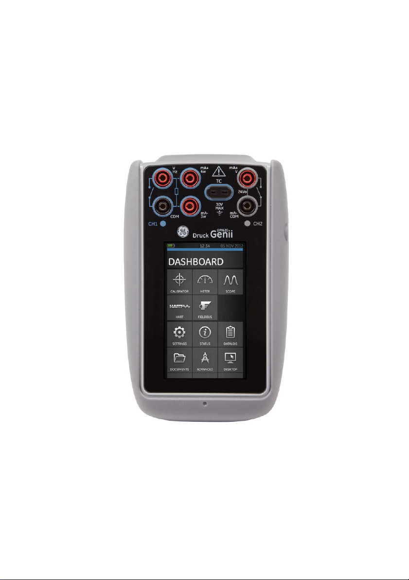
The Druck DPI620 Genii is a battery-powered instrument
for electrical measure and source operations and HART®
communications. The Druck DPI620 Genii also supplies the
power and user interface functions for all optional items.
The touch-screen displays up to six different parameters.
This version of the manual is applicable to software
revisions DK420 v2.01 and above.
1.1 Equipment in the Box
The following items are supplied with the Druck DPI 620
Genii:
• DC power supply
• Li-polymer battery
• Set of six test leads
• AC Probe
• Quick Start Guide
• Stylus
28 April 2014 K0541 issue 2 Page 9 of 200

User Manual Druck DPI620 Genii
1.2 Optional Items
The items that follow are optional items which can be used
with the Druck DPI 620 Genii:
• Pressure Module Carrier, MC 620, this attaches directly
to the Druck DPI 620 Genii to make a fully integrated
pressure instrument.
• Pressure Module, PM 620, this attaches to the pressure
module carrier (MC 620) or a Pressure Station (PV 62X) to
enhance the pressure measurement functionality.
• Pressure Stations, PV 62X, if the Druck DPI 620 Genii is
installed in a Pressure Station, it becomes a fully
integrated pressure calibrator.
1.3 Observance of the User Manual
This manual contains safety and battery installation
information for the Druck DPI 620 Genii. It is the
responsibility of the customer, to make sure that all
personnel operating and maintaining the equipment are
correctly trained and qualified. Before operating or using the
equipment read and obey all sections, including all
WARNINGS and CAUTIONS given in the Quick Start Guide.
28 April 2014 K0541 issue 2 Page 10 of 200

User Manual Druck DPI620 Genii
1.4 General Safety Precautions
Read and obey all the operator's local Health and Safety
regulations and Safe Working Procedures or Practices.
When doing a procedure or task:
• Use only the approved tools, consumable materials
and spares to operate and maintain the equipment.
• Read and obey all applicable WARNING signs.
• Make sure that:
All work areas are clean and clear of
unwanted tools, equipment and materials.
All unwanted consumable materials are
discarded in accordance with local health
and safety and environmental regulations.
28 April 2014 K0541 issue 2 Page 11 of 200

User Manual Druck DPI620 Genii
1.5 General Warnings
• It is dangerous to ignore the specified limits for the
instrument or its related accessories. This can
cause injuries.
• If the equipment is used in a manner not specified
by the manufacturer, the protection provided by
the equipment may be impaired.
• Do not use the instrument in locations with explosive gas,
vapour or dust. There is a risk of an explosion.
• Make sure all equipment is serviceable.
• Use equipment only for the purpose for which it is
provided.
• Wear all applicable Personal Protective Equipment (PPE).
• Do not use sharp objects on the touch-screen.
28 April 2014 K0541 issue 2 Page 12 of 200

User Manual Druck DPI620 Genii
1.6 Electrical warnings
• To prevent electrical shocks or damage to the instrument,
do not connect more than 30V CAT I between the
terminals, or between the terminals and the ground
(earth).
• External circuits should have appropriate insulation to
the mains.
• To prevent electrical shocks, use only the GE specified
AC probe (Part: IO620-AC) to measure AC voltages
that are more than 20 Vrms. Do not connect more
than 300V CAT II between the IO620-AC leads, or
between the leads and the ground (earth). Attach it to
the specified connections only.
• This instrument uses a Lithium-Polymer (Li-Polymer)
battery pack. To prevent an explosion or fire, do not
short circuit, do not disassemble, and keep it safe
from damage.
• To prevent an explosion or fire, use only the GE
specified battery (Part: 191-356), power supply (Part:
191-339) and battery charger (Part: IO620-CHARGER).
• To prevent battery leakage or heat generation, only
use the battery charger and power supply in the
temperature range 0°C to 40°C (32°C to 104°F).
• The power supply input range is 100 – 240Vac, 50 to 60Hz,
250mA, installation category CAT II.
• Position the power supply so not to obstruct the supply
disconnecting device.
28 April 2014 K0541 issue 2 Page 13 of 200

User Manual Druck DPI620 Genii
• Note that the operating and storage temperature range
of the mains PSU does not match that of the DPI620.
Mains PSU operating temperature range 0°C to +40°C,
storage temperature range -40°C to +70°C.
• The DC input to the DPI620 Genii is rated at 5V (+/-5%).
Maximum current 2 Amps.
• To make sure the display shows correct data,
disconnect the test leads before power is set to on or
changing to another measure or source function.
• Make sure the power is OFF before connecting or
disconnecting the probe.
.
• Keep the probe and leads free from all contaminants
28 April 2014 K0541 issue 2 Page 14 of 200

User Manual Druck DPI620 Genii
Overvoltage
Description
Overvoltage category I has the least severe
Overvoltage category II describes an electrical
The following summary of installation and measurement
overvoltage categories are derived from IEC61010-1.
The overvoltage categories indicate the severity of
overvoltage transients
Category
overvoltage transients. Generally CAT I
CAT I
equipment is not designed to be directly
connected to the mains supply. Examples of CAT I
equipment are process loop powered devices
installation where typically single phase
CAT II
equipment is connected. Examples of such
equipment are appliances and portable tools
28 April 2014 K0541 issue 2 Page 15 of 200

User Manual Druck DPI620 Genii
1.7 Pressure Warnings
• Some liquid and gas mixtures are dangerous. This
includes mixtures that occur because of
contamination. Make sure that the equipment is safe
to use with the necessary media.
• To prevent a dangerous release of pressure, isolate
and bleed the system before disconnecting a
pressure connection.
• To prevent a dangerous release of pressure, make
sure that all the related pipes, hoses and equipment
have the correct pressure rating, are safe to use and
are correctly attached.
• To prevent damage to the Druck DPI 620 Genii, only
use it within the specified pressure limits.
• Do not exceed the maximum pressures stated in the
appropriate component manual for the unit under test.
• Reduce pressure at a controlled rate when venting to
atmosphere.
• Carefully de-pressurize all pipes to atmospheric
pressure before disconnecting and connecting to the
unit under test.
• Observe cleanliness when using the instrument.
• Severe damage can be caused if equipment
connected to this instrument is contaminated.
• Connect only clean equipment to the instrument. To
avoid any contamination, an external filter is
recommended.
28 April 2014 K0541 issue 2 Page 16 of 200

User Manual Druck DPI620 Genii
1.8 Preparing the Instrument
On receipt of the instrument check the contents in the
box, listed in section 1.1. It is recommended to retain the
box and packaging for future use.
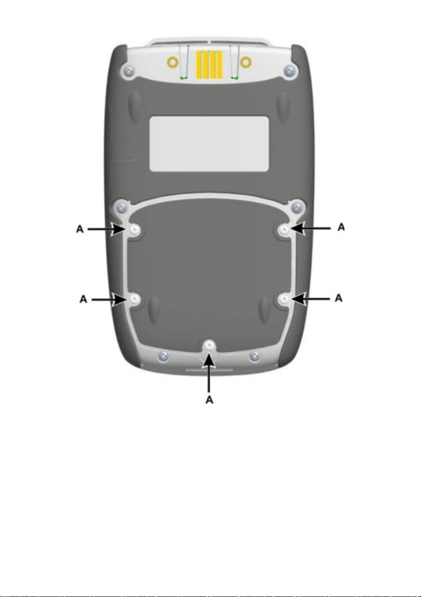
1.9 Install the Battery
1. Remove the five Pozidriv screws (A) (Ref: Figure 1-1).
2. Remove the battery cover.
3. Check the connections on the battery line up with the
connections in the battery compartment.
4. Place the battery in the battery compartment.
5. Replace the battery cover.
6. Secure the cover with the five Pozidriv screws.
28 April 2014 K0541 issue 2 Page 17 of 200
User Manual Druck DPI620 Genii
Figure 1-1
28 April 2014 K0541 issue 2 Page 18 of 200

User Manual Druck DPI620 Genii
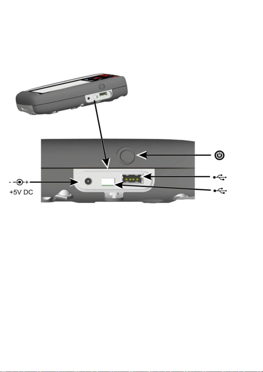
1.10 Charge the Battery
1. Connect the DC power supply into the +5V DC
connection on the side of the unit (Ref: Figure 1-3).
2. The battery can also be charged using the USB
connections (Ref: Figure 1-3).
3. The unit can be On or Off when charging. Charging
times may be longer if charging when the unit is
switched on.
Battery Charging Times 1.10.1
Charging Connection Charge Time
DC Power Supply 6.5 hours
External Battery Charger 6.5 Hours
28 April 2014 K0541 issue 2 Page 19 of 200
User Manual Druck DPI620 Genii
1.11 Basic Modes Power On 1.11.1
From OFF – momentarily press the power button until the
display flashes (Ref: Figure 1-3) .
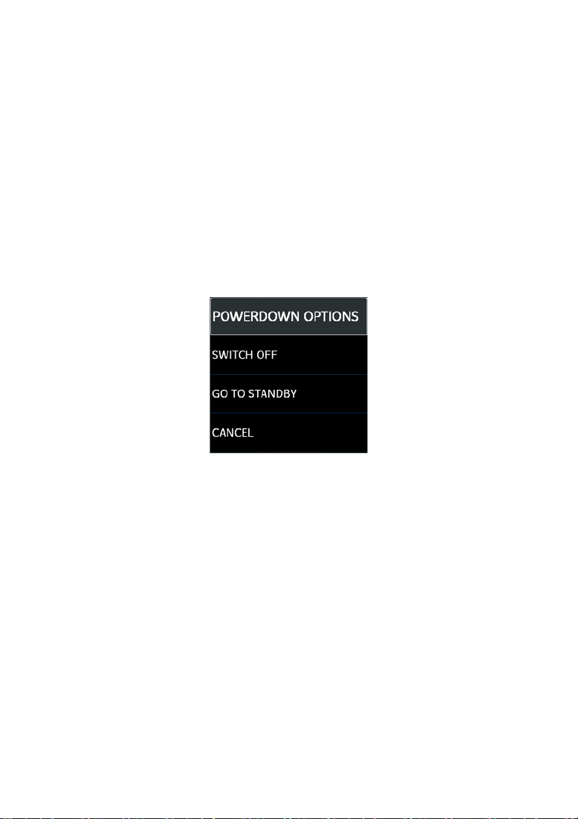
Power Off 1.11.2
Press and Release the Power Button:
The POWERDOWN OPTIONS window will be displayed
Figure 1-2 Powerdown Options
SWITCH OFF – Full power down of Druck DPI 620 Genii –
recommended if unit is not going to be used for several
hours (Requires full reboot on next power up)
STANDBY – DPI620G placed in standby mode – reduced
power consumption from operating mode – recommended
if unit is to be inactive for short periods. (Druck DPI 620 Genii
has fast turn on from STANDBY mode).
Note: SWITCH OFF can also be achieved by pressing and
holding the power button until the screen is blank.
28 April 2014 K0541 issue 2 Page 20 of 200
User Manual Druck DPI620 Genii
Power up from Standby Mode 1.11.3
When powered-up from standby mode the instrument
always opens the last screen shown before going into
standby mode.
Figure 1-3
28 April 2014 K0541 issue 2 Page 21 of 200

User Manual Druck DPI620 Genii
1.12 Druck DPI 620 Genii, Modes
The Druck DPI 620 Genii can be used as follows:
• Calibrator (with independent functions on each of six
channels).
- Data logging capabilities
- Documenting capabilities
• HART® Communicator.
• Foundation Field-bus Communicator.
28 April 2014 K0541 issue 2 Page 22 of 200
User Manual Druck DPI620 Genii
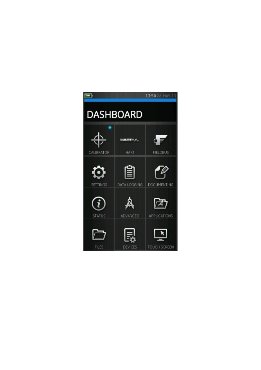
Dashboard navigation 1.12.1
The Dashboard is navigated by swiping a finger from top
to bottom while touching the screen. Functions screens
are navigated by swiping a finger from right to left while
touching the screen.
Figure 1-4 Dashboard
Note: Fieldbus is not installed on all units
28 April 2014 K0541 issue 2 Page 23 of 200
User Manual Druck DPI620 Genii
Set Date, Time and Language 1.12.2
To access Date, Time and Language menus select:
DASHBOARD >> SETTINGS >> DATE
>> TIME
>> LANGUAGE
Themes 1.12.3
Two themes are available: Dark and Light; select the correct
theme for the light level. Select:
DASHBOARD >> SETTINGS >> THEME
Druck DPI 620 Genii Manual 1.12.4
Select the Help icon on the Dashboard to access the
manual. All the information required to operate the Druck
DPI 620 Genii, is in the Help section of the Dashboard
which is accessed by selecting:
DASHBOARD >> HELP
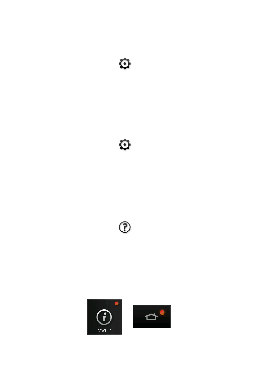
Alarm Status 1.12.5
An Alarm Status is indicated on the DASHBOARD with a Red
LED on the Status button and on the Home button on other
screens.
28 April 2014 K0541 issue 2 Page 24 of 200
User Manual Druck DPI620 Genii
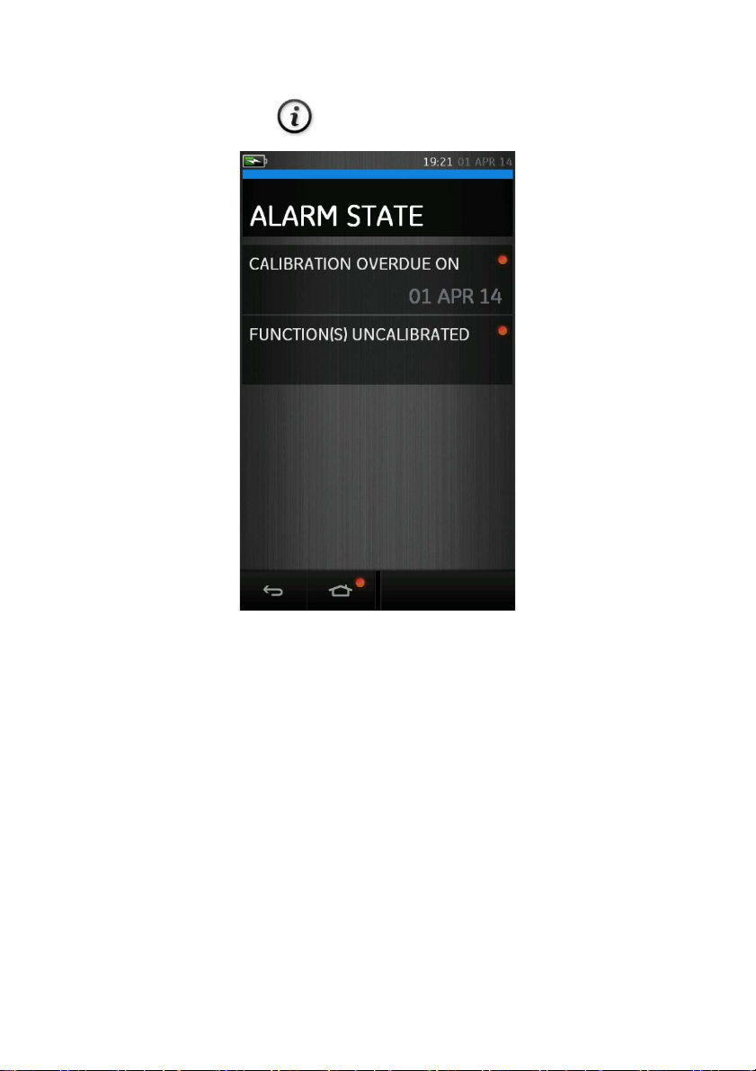
To View Alarms select:
DASHBOARD >> STATUS >> ALARM STATE
Figure 1-6 Alarm State
Selecting the Alarm will clear the indication until the next
power down.
28 April 2014 K0541 issue 2 Page 25 of 200

User Manual Druck DPI620 Genii
1.13 Software and Firmware Upgrades Viewing Software Revision 1.13.1
The software revisions running on the Druck DPI 620 Genii
can be viewed by selecting:
DASHBOARD >> STATUS >> SOFTWARE BUILD
Note: If the software revision number is highlighted red then
an upgrade is available.
Upgrading the Software 1.13.2
Follow the website instructions to download the files onto
a USB flash memory device.
www.ge-mcs.com
1. Select:
DASHBOARD >> ADVANCED
2. Enter the calibration PIN: 5487
3. Select the button.
4. Select:
UPGRADE
5. Continue with one of these operations:
28 April 2014 K0541 issue 2 Page 26 of 200

User Manual Druck DPI620 Genii
• Upgrade the Application software and SDC625
Application.
1. Copy the ‘AMC’ application folder into the root of
a USB flash memory device.
2. Put the USB flash memory device in the USB
type A connector.
3. Select:
APPLICATION
4. Follow the on-screen instructions.
Note: The SDC625 HART® Application can only be
upgraded as part of an application upgrade.
• Upgrade the Operating System and Bootloader
software.
1. Create a folder named ‘OS’ in the root of a USB
flash memory device.
2. Copy the files ‘DK418.nb0’ and ‘DK419.nb0’ into
the ‘OS’ folder.
3. Put the USB flash memory device in the USB
type A connector.
4. Select:
OPERATING SYSTEM
5. Follow the on-screen instructions.
Note: The bootloader can only be upgraded as part of
an operating system upgrade.
28 April 2014 K0541 issue 2 Page 27 of 200

User Manual Druck DPI620 Genii
• Upgrade the HART processor Application and Boot
Loader
1. Create a folder named ‘HART’ in the root of a
USB flash memory device.
2. Copy the files ‘DK416.s19’ and ‘DK417.s19’ into
the ‘HART’ folder.
3. Put the USB flash memory device in the USB
type A connector.
4. Select:
HART APPLICATION
5. Follow the on-screen instructions.
Note: The HART bootloader can only be upgraded as
part of an HART application upgrade.
• Upgrade the CH1 FPGA
1. Create a folder named ‘FPGA’ in the root of a
USB flash memory device.
2. Copy the files ‘DK413.bin’’ into the ‘FPGA’ folder.
3. Put the USB flash memory device in the USB
type A connector.
4. Select:
CH1 FPGA
5. Follow the on-screen instructions.
Note: The CH2 cannot be remotely upgraded .
28 April 2014 K0541 issue 2 Page 28 of 200

User Manual Druck DPI620 Genii
• Upgrade the HART Device Library
By default the HART device library is stored on the
micro SD Card.
1. Set the DPI620 Genii USB client port to Storage
Device mode by selecting:
DASHBOARD >> DEVICES >> USB CLIENT PORT
2. Locate the self-extracting file
‘DPI620_DD_library_20**_*.exe’
3. Connect DPI620 Genii Client USB port to PC
USB port. Device will connect to PC as a
Removable Disk.
4. Run ‘DPI620_DD_library_20**_*.exe’ and
extract files to the Removable Disk (this will
take several minutes due to the large file size).
**_* indicates the DD release version from the
HART foundation.
The required directory structure on the micro SD
card is shown in Figure 1-7 Hart DD Directory
Structure.
28 April 2014 K0541 issue 2 Page 29 of 200

User Manual Druck DPI620 Genii
Figure 1-7 Hart DD Directory Structure
Note:
• If a mistake is made during upgrade and there are
no files to upload, follow the on-screen instructions
and complete the procedure.
• When an upgrade completes normally, the initial
operation of the touch screen may be slower (a
period of approximately 30 seconds).
• To make sure the upgrade completed correctly,
use the Status menu.
28 April 2014 K0541 issue 2 Page 30 of 200
 Loading...