

Page 1
GE
Digital Solutions
© 2014 General Electric Company. All Rights Reserved. Specifications are subject
to change without notice. GE is a registered trademark of General Electric
Company. Other company or product names mentioned in this document may
be trademarks or registered trademarks of their respective companies, which
are not affiliated with GE.
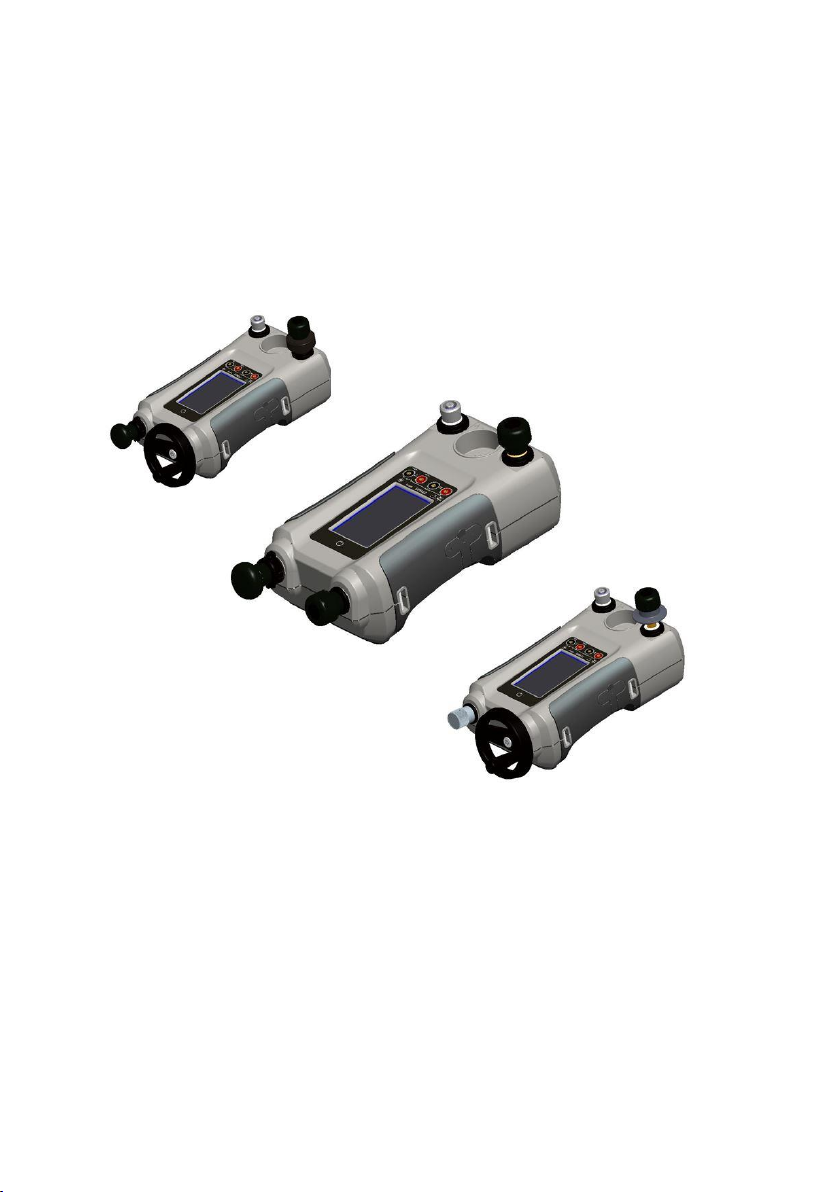
Druck DPI612
Portable Pressure Calibrator
User Manual – 109M4017 Revision A
g
Page 2

User Manual Druck DPI612
Page 2 of 108 [EN] English – 109M4017 Revision A
Revision History
This document supersedes all previously issued versions, providing new
or revised information. The most recent publication can be determined
by comparing the last three characters at the end of the part number
and the date issued.
DPI 612 Portable Pressure Calibrator User Manual
Part Number: 109M4017
Revision
Level
Date
Issued
General Description of Changes
Revision -
07/08/15
First Release
Revision A
27/09/16
Updated to include Leak Test procedure
Page 3

User Manual Druck DPI612
Page 3 of 108 [EN] English – 109M4017 Revision A
Contents
1 INTRODUCTION .............................................................................................................................. 9
EQUIPMENT IN THE BOX .................................................................................................. 9
OBSERVANCE OF THE USER MANUAL ....................................................................... 9
GENERAL SAFETY PRECAUTIONS ................................................................................. 9
WARNINGS .......................................................................................................................... 11
ELECTRICAL SAFETY ........................................................................................................ 11
RECHARGABLE BATTERY WARNINGS ..................................................................... 12
PRESSURE WARNINGS ................................................................................................... 15
OVERVOLTAGE CATEGORY ........................................................................................... 16
PREPARING THE INSTRUMENT ................................................................................... 16
1.9.1 Initial Checks ............................................................................................................ 16
1.9.2 Install Rechargeable Battery and Cradle ................................................... 16
1.9.3 Install Dry Cell Batteries ..................................................................................... 18
PARTS ..................................................................................................................................... 20
1.10.1 DPI 612 ....................................................................................................................... 20
1.10.2 Test Port ..................................................................................................................... 22
1.10.3 Pressure Release Valve....................................................................................... 23
1.10.4 SELECTOR DPI 612 pFlex & pFlexPro (20 & 100 bar) ............................ 23
1.10.5 Pump ........................................................................................................................... 23
1.10.6 Volume Adjuster ..................................................................................................... 24
1.10.7 Refill Valve ................................................................................................................. 26
1.10.8 Priming Pump DPI612 hFlexPro (1000 bar) ............................................... 26
ACCESSORIES: .................................................................................................................... 27
1.11.1 Carry Case (P/N IO612-CASE-3) ...................................................................... 27
1.11.2 Rechargeable Battery pack (P/N CC3800GE) ........................................... 27
1.11.3 Rechargeable Battery and adaptor kit (P/N IO61X-BAT-KIT) ............ 27
1.11.4 Rechargeable Desktop Charger (P/N CX6100GE) .................................. 27
Page 4

User Manual Druck DPI612
Page 4 of 108 [EN] English – 109M4017 Revision A
1.11.5 Mains Adaptor (P/N IO620-PSU) ..................................................................... 27
1.11.6 USB Cable (P/N IO620-USB-PC) ....................................................................... 28
1.11.7 IDOS to USB Converter (P/N IO620-IDOS-USB) ........................................ 28
1.11.8 USB to RS 232 Cable (P/N IO620-USB-RS232) .......................................... 28
1.11.9 Dirt Moisture Trap 20 bar (P/N IO620-IDT621) ......................................... 28
1.11.10 Dirt Moisture Trap 100 bar (P/N IO620-IDT622) ...................................... 28
1.11.11 Pneumatic Hose (PN IO620-HOSE-P1 / IO620-HOSE-P2) ................... 29
1.11.12 Hydraulic Hose (PN IO620-HOSE-H1 / IO620-HOSE-H2) .................... 29
1.11.13 Low Pressure Pneumatic Hose (PN IOHOSE-NP1 / IOHOSE-NP2) .. 29
1.11.14 Pressure Adaptor set ........................................................................................... 30
1.11.15 Comparator Adaptor (P/N IO620-COMP) .................................................... 30
1.11.16 Pressure Module (P/N IPM620-***) ................................................................ 30
1.11.17 Pressure Relief Valve (PRV) ................................................................................ 31
DRUCK DPI612, MODES ................................................................................................. 32
1.12.1 Power ON ................................................................................................................... 32
1.12.2 Power OFF ................................................................................................................. 32
1.12.3 Power up from Standby Mode ........................................................................ 33
NAVIGATION ....................................................................................................................... 33
1.13.1 Set Date, Time and Language ......................................................................... 33
1.13.2 Themes ....................................................................................................................... 34
1.13.3 DRUCK DPI612 Manual ....................................................................................... 34
SOFTWARE AND FIRMWARE UPGRADES ............................................................... 34
1.14.1 Viewing Software Revision ................................................................................ 34
1.14.2 Upgrading the Software ..................................................................................... 34
1.14.3 Upgrade the Application Software ................................................................ 35
1.14.4 Upgrade the Operating System and Boot Loader Software. ........... 35
MAINTENANCE ................................................................................................................... 36
1.15.1 Cleaning ..................................................................................................................... 36
1.15.2 Replace the Batteries ........................................................................................... 36
Page 5

User Manual Druck DPI612
Page 5 of 108 [EN] English – 109M4017 Revision A
INSTRUMENT RETURN.................................................................................................... 36
1.16.1 Returned Material Procedure .......................................................................... 36
1.16.2 Safety Precautions ................................................................................................ 36
1.16.3 Important Notice ................................................................................................... 37
1.16.4 Instrument Disposal in the European Union ............................................ 37
1.16.5 For more information contact ......................................................................... 37
ENVIRONMENT .................................................................................................................. 37
MARKS AND SYMBOLS ON THE EQUIPMENT ....................................................... 38
2 OPERATIONS ................................................................................................................................. 39
COMMON OPERATIONS ................................................................................................. 39
2.1.1 Attach/Remove the device under test ........................................................ 39
2.1.2 Attach a Pressure Relief Valve ........................................................................ 41
2.1.3 Setting a Pressure Relief Valve ....................................................................... 42
DPI 612 PFLEX & PFLEXPRO PNEUMATIC PRESSURE OPERATIONS .......... 43
2.2.1 Introduction .............................................................................................................. 43
2.2.2 Release the Pressure ........................................................................................... 43
2.2.3 Vacuum or Pressure Operation DPI 612 pFlex (20 bar) .................... 44
2.2.1 Release Pressure DPI 612 pFlex (20 bar) ................................................... 44
2.2.2 Vacuum or Pressure Operation DPI 612 pFlexPro (100 bar) ............. 45
2.2.3 Release pressure DPI 612 pFlexPro (100 bar pump) ............................ 47
DPI 612 HFLEXPRO (1000 BAR) HYDRAULIC OPERATIONS. .......................... 47
2.3.1 First Use ..................................................................................................................... 48
2.3.2 Filling and Priming the Pump ........................................................................... 48
2.3.3 Topping up the Hydraulic Fluid ....................................................................... 49
2.3.4 Priming Sequence ................................................................................................. 50
2.3.5 Applying Hydraulic Pressure (1000 bar) ..................................................... 51
2.3.6 Release Hydraulic Pressure (1000 bar pump) ......................................... 52
2.3.7 Drain Excess Hydraulic Fluid ............................................................................ 52
2.3.8 Drain all the Hydraulic Fluid ............................................................................. 53
Page 6

User Manual Druck DPI612
Page 6 of 108 [EN] English – 109M4017 Revision A
CALIBRATOR OPERATIONS ........................................................................................... 55
2.4.1 Basic Calibrator Operation ................................................................................ 55
2.4.2 Set the Function Utility Options ...................................................................... 61
2.4.3 Measurement Display Options ........................................................................ 64
2.4.4 Example Procedures ............................................................................................ 65
PRESSURE CALIBRATION ............................................................................................... 70
2.5.1 Set up a Leak Test ................................................................................................. 71
2.5.2 Set the Pressure Module to Zero .................................................................... 73
2.5.3 Error Indications ..................................................................................................... 73
MEASURE PRESSURE: IDOS OPTION ........................................................................ 73
2.6.1 IDOS Option Assembly Instructions .............................................................. 74
2.6.2 IDOS Function Procedures ................................................................................ 74
3 DATA LOGGING OPERATION .................................................................................................. 76
SET-UP ................................................................................................................................... 77
OPERATION.......................................................................................................................... 78
FILE REVIEW ........................................................................................................................ 79
FILE MANAGEMENT ......................................................................................................... 79
3.4.1 Transfer ...................................................................................................................... 79
3.4.2 Erase ............................................................................................................................ 80
3.4.3 Memory Status ........................................................................................................ 80
DATA FORMAT .................................................................................................................... 80
4 DOCUMENTATION ...................................................................................................................... 82
ANALYSIS .............................................................................................................................. 82
SET-UP ................................................................................................................................... 83
4.2.1 Define the Reference Channel ........................................................................ 83
4.2.2 Define each Input Channel ............................................................................... 83
ANALYSIS FUNCTION ...................................................................................................... 85
RUN PROCEDURE ............................................................................................................. 85
4.4.1 Sequence to Upload and Download file ..................................................... 86
Page 7

User Manual Druck DPI612
Page 7 of 108 [EN] English – 109M4017 Revision A
5 CALIBRATION ................................................................................................................................ 87
GENERAL .............................................................................................................................. 87
CALIBRATION CHECK ...................................................................................................... 87
CALIBRATION ADJUSTMENTS ..................................................................................... 88
BEFORE STARTING ........................................................................................................... 88
PROCEDURES: CURRENT (MEASURE) ....................................................................... 89
PROCEDURES: CURRENT (SOURCE) .......................................................................... 90
PROCEDURES: DC MV/VOLTS (MEASURE) ............................................................. 91
PROCEDURES: DC VOLTS (SOURCE) ......................................................................... 92
PROCEDURES: PRESSURE INDICATOR .................................................................... 93
PROCEDURES: IDOS UPM ............................................................................................. 94
6 ACCESSORY INSTRUCTIONS .................................................................................................. 95
DIRT MOISTURE TRAP 20 BAR (P/N IO620-IDT621) ........................................... 95
6.1.1 Specification: ........................................................................................................... 95
6.1.2 Pressure connections: ......................................................................................... 95
6.1.3 Operation: ................................................................................................................. 95
6.1.4 Cleaning: .................................................................................................................... 96
DIRT MOISTURE TRAP 100 BAR (P/N IO620-IDT622) ........................................ 97
6.2.1 Specification: ........................................................................................................... 97
6.2.2 Pressure connections: ......................................................................................... 97
6.2.3 Operation: ................................................................................................................. 97
6.2.4 Cleaning: .................................................................................................................... 98
7 LEAK TEST PROCEDURES ........................................................................................................ 99
LEAK TEST PROCEDURE FOR DPI612 PFX (UP TO 20BAR) PNEUMATIC ... 99
VACUUM .............................................................................................................................................. 99
LEAK TEST PROCEDURE FOR DPI612 PFP (UP TO 100BAR) PNEUMATIC ......
................................................................................................................................................ 100
VACUUM ............................................................................................................................................ 100
LEAK TEST PROCEDURE FOR DPI612 HFP (UP TO 1000BAR) HYDRAULIC ....
................................................................................................................................................ 101
Page 8

User Manual Druck DPI612
Page 8 of 108 [EN] English – 109M4017 Revision A
8 GENERAL SPECIFICATION .................................................................................................... 102
9 TROUBLESHOOTING ............................................................................................................... 104
DPI 612 PFLEX ................................................................................................................. 104
DPI 612 PFLEXPRO ........................................................................................................ 105
DPI 612 HFLEXPRO ....................................................................................................... 106
GENERAL ........................................................................................................................... 107
10 MANUFACTURER ...................................................................................................................... 108
Page 9

User Manual Druck DPI612
Page 9 of 108 [EN] English – 109M4017 Revision A
1 INTRODUCTION
The Druck DPI612 is a battery-powered instrument for performing
pressure and electrical calibration operations. The Druck DPI612
also supplies the power and user interface functions for all optional
items. The DPI612 uses the PM620 pressure module to allow user
selection of the most suitable pressure range for the task.
EQUIPMENT IN THE BOX
The following are the common items supplied with the Druck DPI612
1/8” NPT & BSP pressure adaptors
Set of four test leads
Safety and Quick Start Guide
Stylus
Hand & Shoulder straps
Refer to DPI612 datasheet for full list of accessories supplied with
each DPI612 model.
OBSERVANCE OF THE USER MANUAL
This manual contains safety and battery installation information for
the Druck DPI612. It is the responsibility of the customer to make
sure that all personnel operating and maintaining the equipment
are correctly trained and qualified. Before using the equipment, read
all sections of this User Manual paying particular attention to all
WARNINGS and CAUTIONS given in the Quick Start Guide.
GENERAL SAFETY PRECAUTIONS
Read and obey all the operator's local health and safety regulations
and safe working procedures or practices when doing a procedure
or task.
Use only the approved tools, consumable materials and spares to
operate and maintain the equipment.
Use equipment only for the purpose for which it is provided.
Page 10

User Manual Druck DPI612
Page 10 of 108 [EN] English – 109M4017 Revision A
Wear all applicable Personal Protective Equipment (PPE).
Do not use sharp objects on the touch-screen.
Observe absolute cleanliness when using the instrument.
Severe damage can be caused if equipment connected to this
instrument is contaminated.
Connect only clean equipment to the instrument. To avoid any
contamination, an external Dirt Moisture Trap (See Section 1.11.9)
is recommended
Some liquid and gas mixtures are dangerous. This includes
mixtures that occur because of contamination. Make sure that the
equipment is safe to use with the necessary media.
Read and obey all applicable WARNING and CAUTIONS signs.
Make sure that:
o All work areas are clean and clear of unwanted tools,
equipment and materials.
o All unwanted consumable materials are disposed in
accordance with local health and safety and
environmental regulations.
o All equipment is serviceable.
Page 11
User Manual Druck DPI612
Page 11 of 108 [EN] English – 109M4017 Revision A
WARNINGS
Do not ignore the specified limits for the instrument or its related
accessories. This can cause injuries.
If the equipment is used in a manner not specified by the
manufacturer, the protection provided by the equipment may be
impaired.
Do not use the instrument in locations with explosive gas, vapour
or dust. There is a risk of an explosion.
ELECTRICAL SAFETY
The DC input to the DPI612 is rated at 5V (+/-5%) 4 Amps.
External circuits should have appropriate insulation to the mains.
To prevent electrical shocks or damage to the instrument, do not
connect more than 30V CAT I between the terminals or between
the terminals and the ground (earth).
This instrument uses a rechargeable battery pack or standard AA
size batteries. To prevent an explosion or fire do not short circuit.
The power supply input range to the optional power supply unit is
100 – 260Vac, 50 to 60Hz, 250mA, installation category CAT II.
When using the optional power supply unit, position the power
supply so as not to obstruct the supply disconnecting device.
Note that the operating and storage temperature range of the
optional PSU does not match that of the DPI612. Mains PSU
operating temperature range 0°C to +40°C, storage temperature
range -40°C to +70°C.
To make sure the display shows the correct data, disconnect the
test leads before power is set to ON or changing to another
measure or source function.
Keep the leads free from all contaminants.
Page 12

User Manual Druck DPI612
Page 12 of 108 [EN] English – 109M4017 Revision A
RECHARGABLE BATTERY WARNINGS
Do not disassemble or modify the battery pack. The battery pack
can leak electrolyte, overheat, emit smoke, burst and/or ignite.
Do not short-circuit the battery.
Do not transport or store the battery pack together with metal
objects. If short-circuiting occurs, over-current will flow, causing
the battery pack to leak electrolyte, overheat, emit smoke, burst
and/or ignite.
Do not discard the battery pack into fire or heat it.
Do not expose cells or batteries to heat or fire. Avoid storage in
direct sunlight.
Do not use or leave the battery pack near a heat source (+80ºC or
higher).
Do not immerse the battery pack in water. Do not allow it to get
wet.
Do not recharge the battery pack near fire or in extremely hot
weather.
To recharge the battery use the DPI611 and DPI612 internal
charging function or the CX6100GE desktop charger. Do not use
any other charger.
Do not subject the battery pack to mechanical shock.
Do not use an apparently damaged or deformed battery pack.
Do not directly solder the battery pack.
Do not reverse the positive (+) and negative (-) terminals.
Page 13

User Manual Druck DPI612
Page 13 of 108 [EN] English – 109M4017 Revision A
Otherwise, during recharging, the battery pack will be reversecharged, abnormal chemical reactions then may occur, or
excessively high current can flow during discharging, leading to
electrolyte leakage, overheating, smoke emission, bursting and/or
ignition.
Do not force the connection if you cannot easily connect the
battery pack terminals to the battery pack charger. Confirm that
the terminals are correctly oriented.
Do not use the battery pack for a purpose other than powering
either DPI611/DPI612 products.
Do not use any battery which is not designed for use with the
equipment.
Do not connect the battery pack to any other electrical outlet.
Do not mix batteries of different manufacture, capacity, size or
type within the DPI611 or DPI612.
If recharging operation fails to complete even when a specified
recharging time has elapsed, immediately stop further recharging.
Do not put the battery pack into a microwave oven. Rapid heating
or disrupted sealing can lead to electrolyte leakage, overheating,
smoke emission, bursting and/or ignition.
If electrolyte leaks from the battery pack or gives off a bad odour,
remove it from any exposed flame. Otherwise, the leaking
electrolyte may catch fire and the battery pack may emit smoke,
burst or ignite.
If the battery pack gives off an odour, generates heat, becomes
discoloured or deformed, or in any way appears abnormal during
use, recharging or storage, immediately remove it from the
equipment or battery pack charger and stop using it. Otherwise,
the problematic battery pack can develop electrolyte leakage,
overheating, smoke emission, bursting and/or ignition.
Page 14

User Manual Druck DPI612
Page 14 of 108 [EN] English – 109M4017 Revision A
Remove the battery from the equipment when not in use.
Do not remove the battery from its original packaging until
required for use.
Secondary batteries need to be charged before use. Always use
the correct charger and refer to the user manual for proper
charging instructions.
Do not leave a battery on prolonged charge when not in use.
After extended periods of storage, it may be necessary to charge
and discharge the battery several times to obtain maximum
performance.
Do not subject the battery pack to intense sunlight or hot
temperatures, for example in a car during hot weather. Otherwise,
electrolyte leakage, overheating and/or smoke emission can occur.
Also, its guaranteed performance will be lost and/or its service life
will be shortened.
The battery pack incorporates built-in safety devices. Do not use it
in a location where static electricity is present.
The guaranteed recharging temperature range is 0°C to +45ºC. A
recharging operation outside this temperature range can lead to
electrolyte leakage and/or overheating of the battery pack and
may cause damage to it.
In the event of a cell leaking, do not allow the liquid to come in
contact with the skin or eyes. If contact has been made, wash the
affected area with copious amounts of water and seek medical
advice.
Seek medical advice immediately if material or content from a
battery has been swallowed
Keep the battery out of the reach of children.
Keep batteries clean and dry.
Page 15
User Manual Druck DPI612
Page 15 of 108 [EN] English – 109M4017 Revision A
Wipe the battery terminals with a clean dry cloth if they become
dirty.
If you find rust, a bad odour, overheating and/or other irregularities
when using the battery pack for the first time, return it to your
supplier or vendor.
For further information contact the nearest distributor or
representative.
Retain the original product literature for future reference.
PRESSURE WARNINGS
It is dangerous to attach an external source of pressure to a
DPI612 pressure station. Use only the internal mechanisms to set
and control pressure in the pressure station.
To prevent a dangerous release of pressure, isolate and bleed the
system before disconnecting a pressure connection.
To prevent a dangerous release of pressure, make sure that all the
related pipes, hoses and equipment have the correct pressure
rating, are safe to use and are correctly attached.
To prevent damage to the DPI612 calibrator, only use it within the
specified pressure limits.
Do not exceed the maximum pressures stated in the appropriate
component manual for the unit under test.
Reduce pressure at a controlled rate when venting to atmosphere.
Carefully de-pressurize all pipes to atmospheric pressure before
disconnecting and connecting to the unit under test.
Always wear appropriate eye protection when working with
pressure.
Page 16

User Manual Druck DPI612
Page 16 of 108 [EN] English – 109M4017 Revision A
OVERVOLTAGE CATEGORY
The following summary of installation and measurement
overvoltage categories are derived from IEC61010-1. The
overvoltage categories indicate the severity of overvoltage
transients.
Table 1-1
Overvoltage
Category
Description
CAT I
Overvoltage category I has the least severe overvoltage
transients. Generally CAT I equipment is not designed to be
directly connected to the mains supply. Examples of CAT I
equipment are process loop powered devices.
CAT II
Overvoltage category II describes an electrical installation
where typically single phase equipment is connected.
Examples of such equipment are appliances and portable
tools.
PREPARING THE INSTRUMENT
On receipt of the instrument check the contents in the box, listed in
accessories See Section 1.11. It is recommended to retain the box
and packaging for future use.
1.9.1 Initial Checks
Before you use the instrument for the first time:
Make sure that there is no damage to the instrument, and that
there are no missing items; See Section 1.11.
Remove the plastic film that protects the display.
1.9.2 Install Rechargeable Battery and Cradle
For a new unit steps 1-4 will have been completed in the factory
prior to delivery.
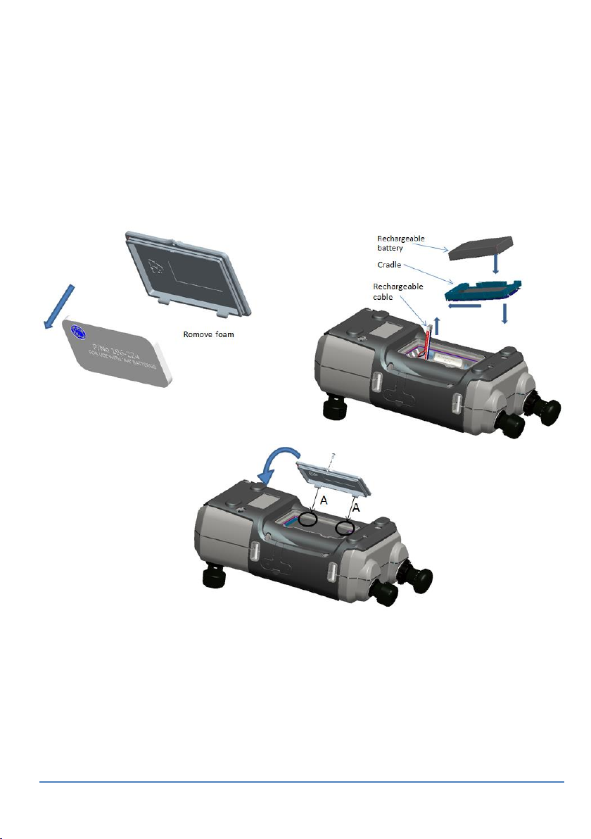
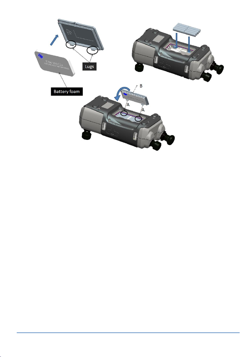
1. Remove the battery cover by loosening the captive battery cover
fixing screw and lifting the cover upwards.
2. If fitted, remove white battery holder by pulling straight up to
reveal charging cable. Remove foam block from battery cover.
Page 17
User Manual Druck DPI612
Page 17 of 108 [EN] English – 109M4017 Revision A
3. Connect the charging cable to the rechargeable battery cradle.
4. Push the cradle firmly into the battery compartment.
5. Insert the rechargeable battery into the cradle.
6. Replace the battery cover by pressing the lugs inside
the slots (A) and bring down the cover, securing by tightening the
fixing screw. (See Figure 1-1).
7. The battery can be charged by connecting the wall adapter to the
unit or by using the optional desktop charger.
Figure 1-1 Fit Rechargeable Pack
Page 18

User Manual Druck DPI612
Page 18 of 108 [EN] English – 109M4017 Revision A
1.9.3 Install Dry Cell Batteries
1. Remove the battery cover by loosening the captive battery cover
fixing screw and lifting the cover upwards.
2. If the rechargeable battery has been fitted, remove it.
3. If the rechargeable battery cradle has been fitted, remove it by
gently pulling it straight up. Avoid touching the metal contacts on
the cradle. Note the cradle is attached to the unit with the
charging cable.
4. Disconnect the charging cable from the back of the cradle and
keep it loose in the small compartment then fit battery holder.
5. Fit the foam block to the battery cover.
6. Place the batteries in the battery compartment with the correct
+/– position.
Incorrect Insertion of batteries can cause battery failure.
7. Replace the battery cover by pressing the lugs inside
the slots (A) and bring down the cover, securing by tightening the
fixing screw. (See Figure 1-2).
Page 19
User Manual Druck DPI612
Page 19 of 108 [EN] English – 109M4017 Revision A
Figure 1-2 Fit Dry Cell Batteries
Page 20
User Manual Druck DPI612
Page 20 of 108 [EN] English – 109M4017 Revision A
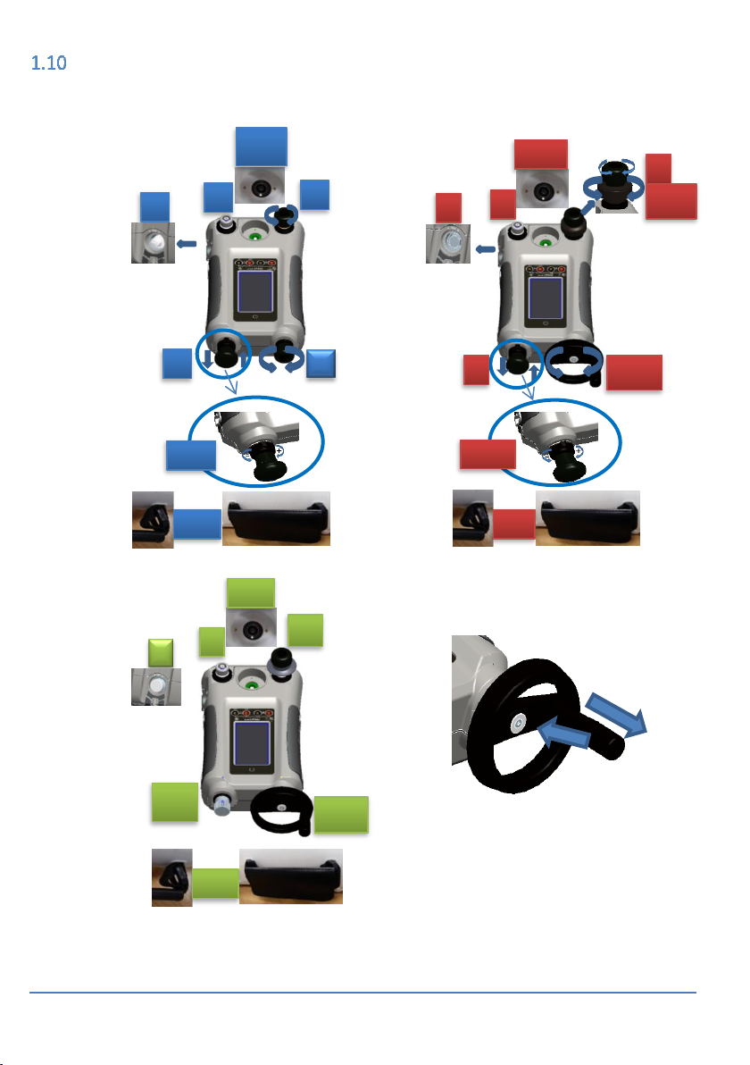
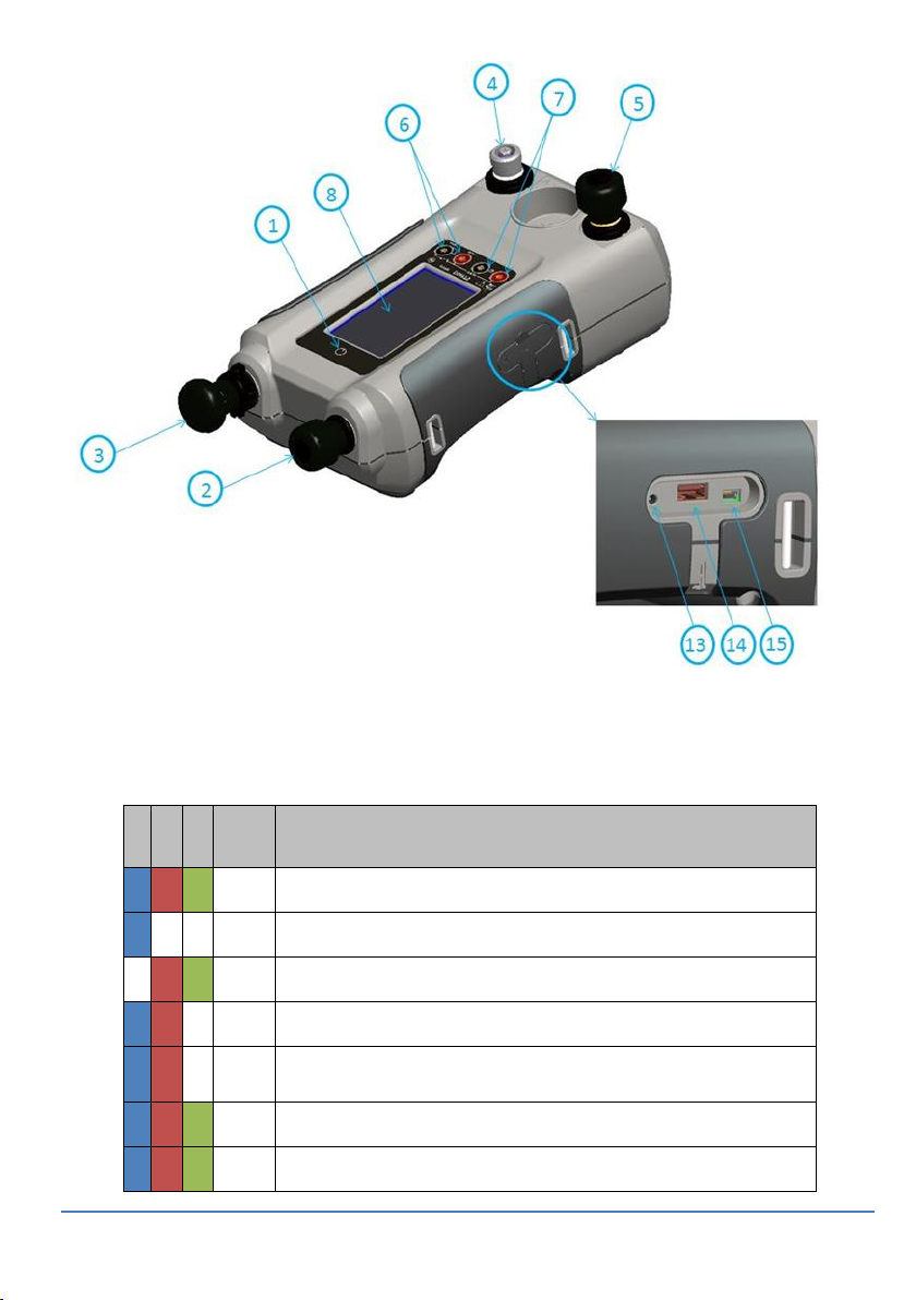
PARTS
1.10.1 DPI 612
9
4
5
5.1
3
10
2.1
1
9
5
12
2.1
11
10
Page 21
User Manual Druck DPI612
Page 21 of 108 [EN] English – 109M4017 Revision A
Figure 1-3 DPI612 Pressure Calibrator
Table 1-2
Item
No.
Description
1
ON or OFF button.
2 PFX only: Pneumatic volume adjuster.
2.1
PFP, HFP models only: Volume adjuster wheel with fold-in handle.
3 Pump mechanism.
3.1
PFX, PFP models only: Pressure/vacuum selector to set the pump
operation: pressure (+), vacuum (-).
4 Test port: To attach the device under test.
5 Pneumatic pressure release valve to release pressure in the system.
Page 22

User Manual Druck DPI612
Page 22 of 108 [EN] English – 109M4017 Revision A
Item
No.
Description
5.1
PFP models only: Pneumatic refill valve. Close it to seal off the device
pressure and refill the pressure mechanism.
6 CH1 connectors for: Voltage (V); Current (mA+, mA-); Switch operation.
7 Isolated CH2 connectors for: Voltage (V); 24 V loop power supply (24
Vo).
8 Liquid Crystal Display (LCD): Color display with touch-screen. To make
a selection, lightly tap on the applicable display area.
9 Optional accessory (not shown): Pressure connection for a relief valve
(PRV). A blanking plug is standard.
10
Pressure and electrical connections for a PM620 module (not shown):
DPI612 models PFX and PFP: Seal the pressure connection with a
blanking plug (Part: IO620-BLANK) or a PM 620 module.
DPI612 HFP models only: The pressure connection seals itself.
11
HFP models only: Hydraulic refill valve (not shown): Close it to seal off
the device pressure and refill the pressure mechanism with fluid.
12
Hand straps
13
+5 V DC power input socket. This supply also charges the optional
battery pack.
14
USB type A connector for connections to external peripherals (USB
flash memory or optional external modules).
15
USB mini-type B connector for communication with a computer.
1.10.2 Test Port
To attach the device under test, the test port uses “Quick
fit” pressure adaptors; See Section 1.11.12. These are easy
to remove, change and install; See Section 2.1.1
(Attach/Remove the device under test).
Figure 1-4
Test port
Page 23
User Manual Druck DPI612
Page 23 of 108 [EN] English – 109M4017 Revision A
1.10.3 Pressure Release Valve
This is a needle point valve that lets you release the
pressure or vacuum, or seal the system.
Figure 1-5
Pressure
Release Valve
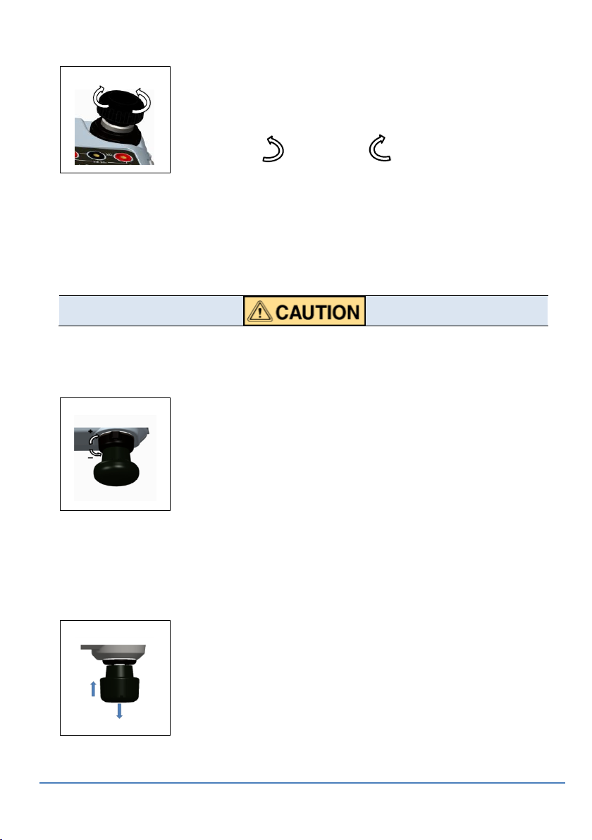
1.10.4 SELECTOR DPI 612 pFlex & pFlexPro (20 & 100 bar)
Before you turn the pressure/vacuum selector to + or -, release all the
pressure. Sudden high pressure in the pump mechanism can cause damage.
This control sets the operation of the instrument (pressure
or vacuum). To prevent a pressure leak, turn it fully
clockwise or counter clockwise.
+: Pressure, - : Vacuum
Figure 1-6
Selector
1.10.5 Pump
DPI 612 pFlex (20 bar) Pump
When you have set the operation to pressure or vacuum (See
Section 1.10.4), seal the system (See Section 1.10.3) and use the
pump to set the necessary pressure or vacuum.
You can then make the last adjustments with the volume
adjuster (See Section 1.10.6).
Figure 1-7
20 bar Pump
OPEN CLOSE
Page 24
User Manual Druck DPI612
Page 24 of 108 [EN] English – 109M4017 Revision A
DPI 612 pFlexPro (100 bar) Pump
When you have set the operation to pressure or vacuum (See
Section 1.10.4), seal the system (See Section 1.10.3) and use the
pump to set the necessary pressure or vacuum.
You can then make the last adjustments with the volume
adjuster (See Section 1.10.6).
Figure 1-8
100 bar Pump
DPI 612 hFlexPro (1000 bar) Pump
When you have set the operation to pressure or vacuum
(See Section 1.10.4), seal the system (See Section 1.10.3)
and use the pump to set the necessary pressure or
vacuum.
You can then make the last adjustments with the volume
adjuster (See Section 1.10.6).
Figure 1-9
1000 bar
Pump
1.10.6 Volume Adjuster
DPI 612 pFlex (20 bar) Volume Adjuster
This control increases or decreases the pressure/vacuum.
Before you seal the system (See Section 1.10.3), turn this
control to the necessary position:
For equal adjustment, turn it to the middle of
its range.
For maximum adjustment, turn it fully
clockwise or counter clockwise.
When you have set the necessary pressure or vacuum
with the pump (See Section 1.10.5), use the volume
adjuster to make the fine adjustments.
Figure 1-10
20 bar
Volume
Adjuster
Page 25

User Manual Druck DPI612
Page 25 of 108 [EN] English – 109M4017 Revision A
DPI 612 pFlexPro (100 bar) Volume Adjuster
This control increases or decreases the pressure/vacuum.
Before you seal the system (See Section 1.10.3), turn this
control to the necessary position:
For equal adjustment, turn it to the middle of
its range.
For maximum adjustment, turn it fully
clockwise or counter clockwise.
When you have set the necessary pressure or vacuum
with the pump (See Section 1.10.5), use the volume
adjuster to make the fine adjustments.
Figure 1-11
100 bar
Volume
Adjuster
DPI 612 hFlexPro (1000 bar) Volume Adjuster
This control increases or decreases the pressure/vacuum.
Before you seal the system (See Section 1.10.3), turn this
control to the necessary position:
For equal adjustment, turn it to the middle of
its range.
For maximum adjustment, turn it fully
clockwise or counter clockwise.
When you have set the necessary pressure or vacuum
with the pump (See Section 1.10.5), use the volume
adjuster to make the fine adjustments.
Figure 1-12
1000 bar
Volume
Adjuster
Page 26
User Manual Druck DPI612
Page 26 of 108 [EN] English – 109M4017 Revision A
1.10.7 Refill Valve
DPI 612 pFlexPro (100 bar) Refill Valve
When pressurising large volumes this can be used to refill
the pump without releasing pressure from the UUT (see
Section 2.2.2)
Figure 1-13
100 bar Refill
Valve
DPI612 hFlexPro (1000 bar) Refill Valve
When pressurising large volumes this can be used to refill
the pump without releasing pressure from the UUT (see
Section 0)
Figure 1-14
1000 bar
Refill Valve
1.10.8 Priming Pump DPI612 hFlexPro (1000 bar)
This control is used to fill and generate a priming pressure
on the UUT (approx. 10 bar max)
(see Section 0)
Figure 1-15
1000 bar
Priming
Pump
Page 27
User Manual Druck DPI612
Page 27 of 108 [EN] English – 109M4017 Revision A
ACCESSORIES:
1.11.1 Carry Case (P/N IO612-CASE-3)
A tailored fabric carry case with carrying strap allows the DPI612 to
be used without removing it from the case.
1.11.2 Rechargeable Battery pack (P/N CC3800GE)
Use in place of AA cells. The battery pack is charged
within the instrument.
1.11.3 Rechargeable Battery and adaptor kit (P/N IO61X-BAT-KIT)
Kit contains 3.7V Li-ion battery, Cradle, Battery Cover and
power adapter.
1.11.4 Rechargeable Desktop Charger (P/N CX6100GE)
To Charge the Li-ion battery outside of the unit.
1.11.5 Mains Adaptor (P/N IO620-PSU)
A universal input mains adaptor (Input voltage 100 to
240VAC (50/60Hz) and Mains socket adaptors are
provided.
Page 28
User Manual Druck DPI612
Page 28 of 108 [EN] English – 109M4017 Revision A
1.11.6 USB Cable (P/N IO620-USB-PC)
It connects the DPI612 to a PC via a USB port.
1.11.7 IDOS to USB Converter (P/N IO620-IDOS-USB)
It allows connection of an IDOS universal pressure
module to the DPI612. USB Cable (P/N IO620-USB-PC) is
also required to connect the converter to the DPI612
USB port.
1.11.8 USB to RS 232 Cable (P/N IO620-USB-RS232)
It connects the DPI612 to an RS232 interface.
1.11.9 Dirt Moisture Trap 20 bar (P/N IO620-IDT621)
It prevents contamination of the DPI612 PFLEX
pneumatic system and cross contamination from one
device under test to another. The trap connects directly to
the pressure port and replicates the quick fit connection
for compatibility with standard adaptors, adaptor kits and
hoses. User instructions are in section 6.1
1.11.10 Dirt Moisture Trap 100 bar (P/N IO620-IDT622)
It prevents contamination of the DPI612 PFlexPro
pneumatic system and cross contamination from one
device under test to another. The trap connects directly
to the pressure port and replicates the quick fit
connection for compatibility with standard adaptors,
adaptor kits and hoses. User instructions are in section
6.2
Page 29
User Manual Druck DPI612
Page 29 of 108 [EN] English – 109M4017 Revision A
1.11.11 Pneumatic Hose (PN IO620-HOSE-P1 / IO620-HOSE-P2)
A high pressure pneumatic hose rated to 400 bar (5800
psi). The hose connects directly to the DPI612 pressure
port and replicates the quick fit connection for
compatibility with the standard adaptors supplied and
the other adaptor kits.
P/N IO620-HOSE-P1: 1m/3,2ft pneumatic adaptor hose
P/N IO620-HOSE-P2: 2m/6.4ft pneumatic adaptor hose
1.11.12 Hydraulic Hose (PN IO620-HOSE-H1 / IO620-HOSE-H2)
A high pressure Hydraulic hose rated to 1000 bar
(15000 psi). The hose connects directly to the DPI612
pressure port and replicates the quick fit connection for
compatibility with the standard adaptors supplied and
the other adaptor kits.
P/N IO620-HOSE-H1: 1m/3,2ft pneumatic adaptor hose
P/N IO620-HOSE-H2: 2m/6.4ft pneumatic adaptor hose
1.11.13 Low Pressure Pneumatic Hose (PN IOHOSE-NP1 / IOHOSE-NP2)
A low pressure pneumatic hose rated to 20 bar (300 psi). The hose
connects directly to the DPI612 pressure port and replicates the
quick fit connection for compatibility with the standard adaptors
supplied and the other adaptor kits.
P/N IOHOSE-NP1: 1m/3,2ft pneumatic adaptor hose
P/N IOHOSE-NP2: 2m/6.4ft pneumatic adaptor hose
Page 30
User Manual Druck DPI612
Page 30 of 108 [EN] English – 109M4017 Revision A
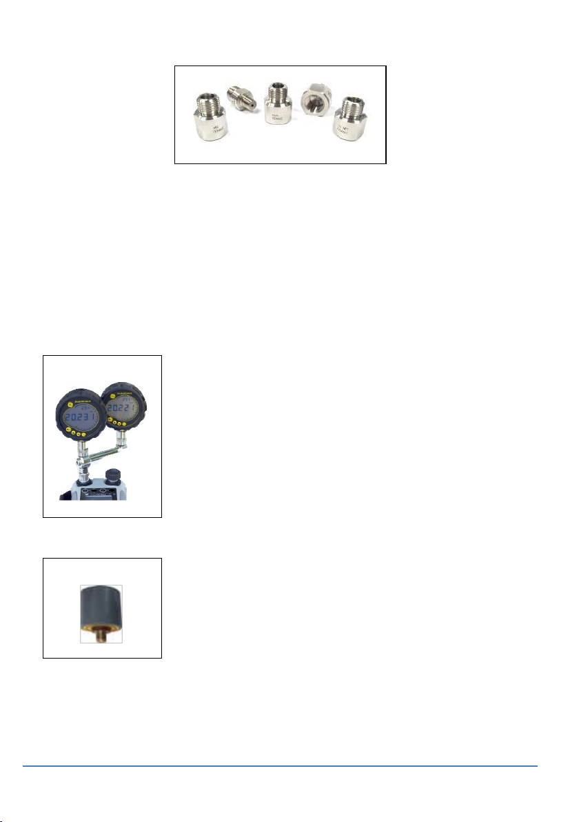
1.11.14 Pressure Adaptor set
A set of test point adaptors to connect the tool-less quick fit DPI612
pressure port or the extension hoses to the device under test.
P/N IO620-BSP: G1/8 male and G1/4 male, G1/4 female, G3/8
female and G1/2 female.
P/N IO620-NPT: 1/8” male and ¼” male, ¼” female, 3/8” female
and ½” female.
P/N IO620-MET: 14mm female and 20mm female.
1.11.15 Comparator Adaptor (P/N IO620-COMP)
For greater efficiency, two test devices can be
connected at the same time. The adaptor connects to
the pressure port of the DPI612 and provides two outlet
ports. It is compatible with the standard adaptors
supplied and the adaptor kits.
1.11.16 Pressure Module (P/N IPM620-***)
Select the best pressure range for the job from an
extensive list of high accuracy pressure ranges. Ranges
available from 25mbar upto 1000 bar (10 In H2O upto
15000 psi)
Page 31

User Manual Druck DPI612
Page 31 of 108 [EN] English – 109M4017 Revision A
1.11.17 Pressure Relief Valve (PRV)
To give your attached devices overpressure protection
(device under test, PM 620 module), we recommend you
use one of our range of optional PRVs;
Available for pneumatic and hydraulic versions
Page 32

User Manual Druck DPI612
Page 32 of 108 [EN] English – 109M4017 Revision A
DRUCK DPI612, MODES
1.12.1 Power ON
From OFF – momentarily press the power button until the GE Logo
appears.
Figure 1-16 Power Button
1.12.2 Power OFF
Press and Release the Power Button:
Select SWITCH OFF from the POWERDOWN OPTIONS window
displayed.
Figure 1-17 Power Down Options
SWITCH OFF – Full power down of DPI612 – Recommended if unit is
not going to be used for several hours (Requires full reboot on next
power up).
GO TO STANDBY– DPI612 placed in standby mode – Reduced power
consumption from operating mode – recommended if unit is to be
inactive for short periods. (DPI612 has fast turn on from STANDBY
mode).
CANCEL – Touch CANCEL option if you do not want to Switch Off or
Standby the instrument.
Power ON/OFF
Page 33

User Manual Druck DPI612
Page 33 of 108 [EN] English – 109M4017 Revision A
1.12.3 Power up from Standby Mode
When powered-up from standby mode the instrument always opens
the last screen shown before going into standby mode.
NAVIGATION
On power up the DPI612 displays the Dashboard. The user should
select the desired option by touching the appropriate icon. Function
screens are navigated by swiping a finger from right to left while
touching the screen. List menus are navigated by swiping a finger
up and down while touching the screen.
Figure 1-18 Dash Board
1.13.1 Set Date, Time and Language
To access Date, Time and Language menus
Select:
Note: The DPI612 will maintain the date and time for 30 days after
being left without batteries. In case of loss of date and time, replace
the batteries, connect the mains adaptor to the DPI612 and keep it
turned on for 50 hours to fully recharge the clock battery.
DASHBOARD >> SETTINGS >> DATE
Page 34

User Manual Druck DPI612
Page 34 of 108 [EN] English – 109M4017 Revision A
1.13.2 Themes
Two themes are available: Dark and Light; select the correct theme
for the light level.
Select:
1.13.3 DRUCK DPI612 Manual
Select the Help icon on the Dashboard to access the manual. The
manual can be downloaded onto a memory stick for viewing or
printing on a remote PC.
SOFTWARE AND FIRMWARE UPGRADES
1.14.1 Viewing Software Revision
The software revisions running on the DPI612 can be viewed by
selecting:
Note: If the software revision number is highlighted red then an
upgrade is available.
1.14.2 Upgrading the Software
Follow the website instructions to download the files onto a USB
flash memory drive.
www.gemeasurement.com
Enter the calibration PIN: 5487; Select the button and continue
upgrade with one of these operations.
DASHBOARD >> SETTINGS >> THEME
DASHBOARD >> HELP
DASHBOARD >> SETTINGS >> STATUS
>> SOFTWARE BUILD
DASHBOARD >> SETTINGS
>> ADVANCED
Page 35

User Manual Druck DPI612
Page 35 of 108 [EN] English – 109M4017 Revision A
1.14.3 Upgrade the Application Software
1. Copy the ‘AMC’ application folder into the root of a USB
flash memory device.
2. Put the USB flash memory drive into the USB type A
connector.
3. Select:
4. Follow the on-screen instructions.
1.14.4 Upgrade the Operating System and Boot Loader Software.
1. Copy the ‘OS’ folder into the root of a USB flash memory
device.
2. Put the USB flash memory drive in the USB type A
connector.
3. Select:
4. Follow the on-screen instructions.
Note: The boot loader can only be upgraded as part of an operating
system upgrade.
Notes:
If a mistake is made during upgrade and there are no files to
upload, follow the on-screen instructions and complete the
procedure.
When an upgrade completes normally, the initial operation of the
touch screen may be slower (a period of approximately 30
seconds).
To make sure the upgrade completed correctly, use the Status
menu.
Page 36

User Manual Druck DPI612
Page 36 of 108 [EN] English – 109M4017 Revision A
MAINTENANCE
The DPI612 instrument contains no user serviceable parts and
should be returned to a GE service centre or an approved service
agent for all repairs.
For more information, contact our customer service department at
www.gemeasurement.com
1.15.1 Cleaning
Do not use solvents or abrasive materials.
Clean the case and display with a lint-free cloth and a weak
detergent solution.
1.15.2 Replace the Batteries
To replace the batteries, See Section 1.9.2. Then re-attach the cover.
All the configuration options stay in memory.
INSTRUMENT RETURN
1.16.1 Returned Material Procedure
If the instrument is unserviceable and requires a repair return to a
GE Service Center or approved Service Agents.
Web site: www.gemeasurement.com Contact the GE Service Center,
either by phone, fax or E-mail to obtain a Returned Material
Authorization (RMA) number, providing the following information:
Product (i.e. Druck DPI612)
Serial number
Details of defect/work to be undertaken
Operating conditions
1.16.2 Safety Precautions
Provide information if the product has been in contact with any
hazardous or toxic substances and, the relevant MSDS and or
COSHH references and precautions to be taken when handling.
Page 37

User Manual Druck DPI612
Page 37 of 108 [EN] English – 109M4017 Revision A
1.16.3 Important Notice
Do not use unauthorized sources to service this equipment as this
will affect the warranty and may not guarantee further
performance.
When discarding used equipment and batteries, obey all the local
health and safety procedures.
1.16.4 Instrument Disposal in the European Union
Do not dispose this product or its battery as household waste.
Use an approved organization that collects and/or recycles the
applicable item.
1.16.5 For more information contact
GE Sensing customer service department:
www.gemeasurement.com
ENVIRONMENT
The following conditions apply for both shipping and storage:
Temperature Range -20°C to +70°C (-40°F to +158°F)
Altitude up to 15,000 feet (4,570 meters).
Page 38

User Manual Druck DPI612
Page 38 of 108 [EN] English – 109M4017 Revision A
MARKS AND SYMBOLS ON THE EQUIPMENT
Complies with European Union directives
USB ports: Type A; Mini Type B connector
Ground (Earth)
DC adaptor polarity: the Centre of the plug is
negative
Page 39

User Manual Druck DPI612
Page 39 of 108 [EN] English – 109M4017 Revision A
2 OPERATIONS
Common Operations
2.1.1 Attach/Remove the device under test
Pressurized gases are dangerous. Before you attach or disconnect pressure
equipment, safely release all the pressure
To prevent damage to the instrument, do not let dirt get into the pressure
mechanism. Before you attach equipment, make sure it is clean or use the
applicable dirt trap.
The test port uses “Quick fit” pressure adaptors; See
Section 1.11 (Accessories). These are easy to remove,
change and install (See 1.11.14).
Figure 2-1
Pressure Port
Page 40

User Manual Druck DPI612
Page 40 of 108 [EN] English – 109M4017 Revision A
a. Procedure (to Attach)
Figure 2-2 Attach / Remove Pressure connections
Table 2-1
Step
Procedure
1
Remove the adaptor
2
Use an applicable seal for the pressure connection:
a. NPT type: Use an applicable sealant on the thread.
b. BSP (parallel) type: We recommend a bonded seal at
the bottom.
c. BSP (parallel type, 100 bar (1500 psi) or less: a bonded
seal at the top is permitted.
3
Attach the adaptor to the device; if necessary use one of
the alternative adaptors listed in Section 1.11
(Accessories), then tighten to the applicable torque.
b. (G)/BSPP
P≥100 bar
c. (G)/BSPP
P≤100 bar
Pressure Port
a. NPT
1 2 3
Page 41

User Manual Druck DPI612
Page 41 of 108 [EN] English – 109M4017 Revision A
Step
Procedure
4
Re-attach the adaptor to the test port and tighten it until
it is hand tight only.
b. Procedure (to Remove)
To remove a device, first release the pressure (See Section 2.2.2). You
can then do steps 4, 3, and 1 mentioned in Section2.1.1. But do the
operations in the reverse order.
2.1.2 Attach a Pressure Relief Valve
Optional accessory; see Section 1.11.17. Use a pressure relief valve
(PRV) to set a limit to the pressure you can apply to the pressure
devices attached to the pressure station. The PRV is set at the
factory to operate at the maximum pressure specified on the label.
If the pressure in the instrument is more than the relief pressure set
for the PRV, the PRV controls a slow release of the unwanted
pressure. The correct PRV helps prevent overpressure and damage
to the attached devices.
Pneumatic
Step 1
Step 2
Choose a clean, dry PRV
with the correct pressure
value for the devices you
are using and tighten it
into position (hand tight
only).
Choose a clean, dry PRV
with the correct pressure
value for the devices you
are using and tighten it
into position (hand tight
only).
Note: Before you put it into storage, make sure it is clean and dry.
Page 42

User Manual Druck DPI612
Page 42 of 108 [EN] English – 109M4017 Revision A
Hydraulic
In its normal condition, the DPI 612 hFlexPro contains hydraulic fluid. To
make sure it does not spill out, seal the system and put it on its side before
you install a PRV.
1 2 3
4
Step
Procedure
1
Seal the system.
2
Put the instrument on its side.
3
Remove the blanking plug or, if applicable, the PRV you
are using. To collect possible drops of hydraulic fluid, put
it in a container.
Note: Before you put it into storage, make sure it is clean
and dry.
4
Choose a clean, dry PRV with the correct pressure value
for the devices you are using and tighten it into position
(hand tight only).
2.1.3 Setting a Pressure Relief Valve
The PRV is set at the factory to operate at the maximum pressure
specified on the label (on the plastic cap). For the adjustable range,
refer to data sheet.
If necessary, use these steps to adjust the relief pressure:
Step
Procedure
1
Attach an applicable PM 620 module.
2
Remove the plastic cap from the end of the PRV
3
Set the necessary pressure with the pressure station
Page 43

User Manual Druck DPI612
Page 43 of 108 [EN] English – 109M4017 Revision A
Step
Procedure
4
When the pressure in the pressure station is at the new
PRV pressure, turn the adjustment screw until the PRV
operates:
counter clockwise decreases the operating pressure
clockwise increases the operating pressure
5
Do steps 3 and 4 until the PRV operates at the correct
pressure. Then press the plastic cap back into position.
DPI 612 pFlex & pFlexPro PNEUMATIC PRESSURE OPERATIONS
2.2.1 Introduction
This section gives examples of how to connect and use
the DPI612 pressure calibrator for the necessary
pressure or vacuum operations.
Before you start:
Read and understand the “Safety” section.
Make sure that there is no damage to the
instrument and there are no missing items.
Note: Use only original parts supplied by the
manufacturer.
Figure 2-3
DPI612
Pressure
Calibrator
2.2.2 Release the Pressure
To release all the pressure in this instrument, open the
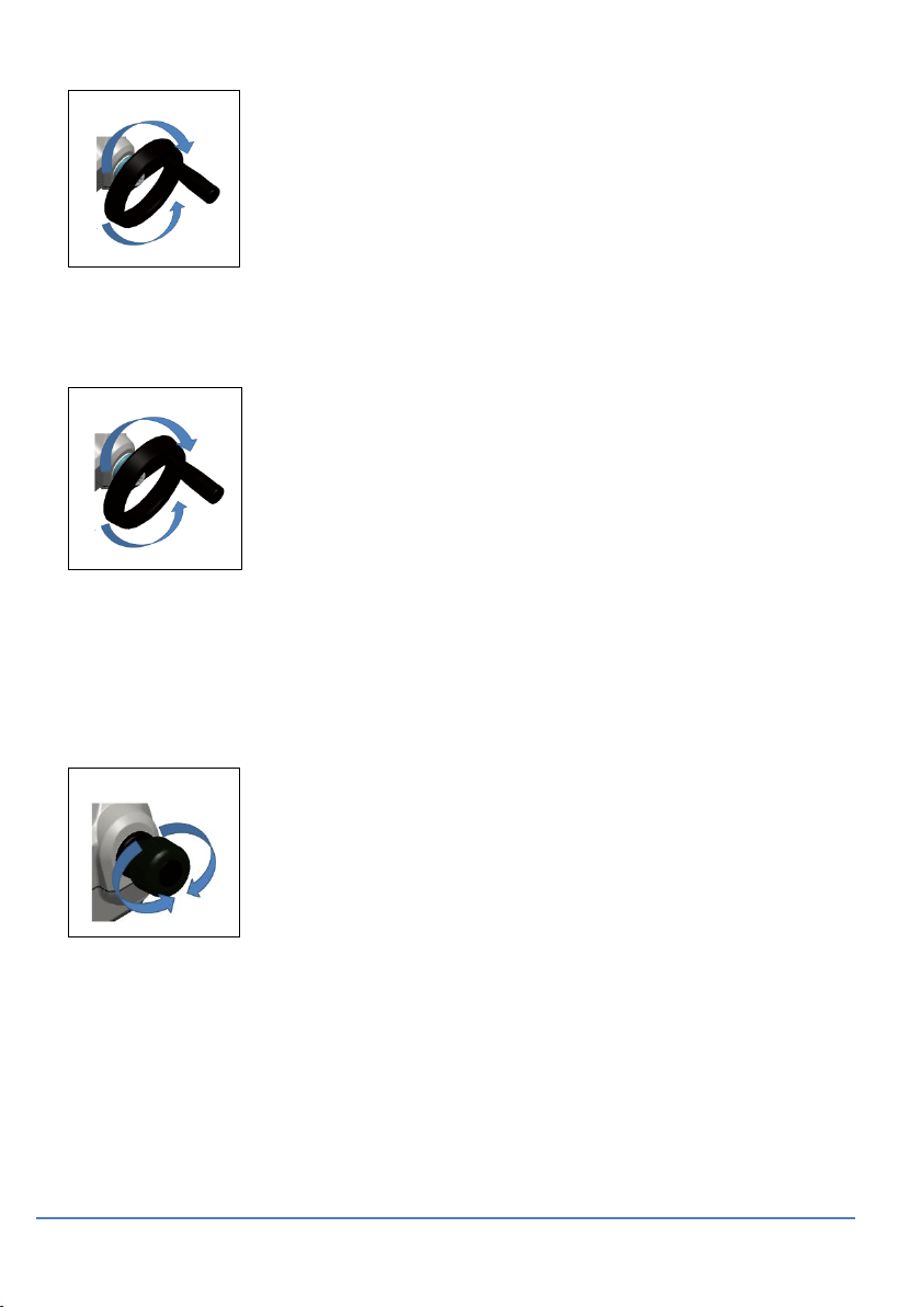
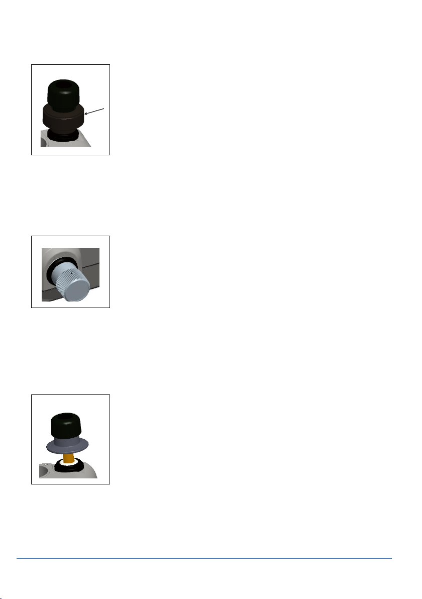
pressure release valve counter clockwise (1 turn).
To control a change in pressure conditions (for example,
to go to or through another test pressure) use the volume
adjuster (See Section 1.10.6) or open and close the
pressure release valve.
Figure 2-4
Pressure
Release Valve
Page 44

User Manual Druck DPI612
Page 44 of 108 [EN] English – 109M4017 Revision A
2.2.3 Vacuum or Pressure Operation DPI 612 pFlex (20 bar)
1 2 3 4 5
Figure 2-5 Vacuum or Pressure operation
2.2.1 Release Pressure DPI 612 pFlex (20 bar)
Open the pressure release valve counter clockwise (1 turn)
Table 2-2
Table 2-3
Step
Procedure (Vacuum)
Step
Procedure (Pressure)
1
Set to vacuum operation
(-).
1 Set to Pressure operation
(+).
2
To do equal adjustments
(up or down) at the end of
the procedure, turn the
volume adjuster to the
middle of its range of
operation.
2 To do equal adjustments
(up or down) at the end of
the procedure, turn the
volume adjuster to the
middle of its range of
operation.
3
Seal the system.
3 Seal the system.
4
Use the pump to set the
maximum vacuum or set
the vacuum you want to
adjust.
4 Use the pump to set the
maximum pressure or set
the pressure you want to
adjust.
5
Adjust the vacuum
(+ decrease; - increase).
5 Adjust the pressure
(+ decrease; - increase).
Page 45

User Manual Druck DPI612
Page 45 of 108 [EN] English – 109M4017 Revision A
Figure 2-6
Pressure
Release
2.2.2 Vacuum or Pressure Operation DPI 612 pFlexPro (100 bar)
1 2 3 4 5
6 7 8 9 10
Figure 2-7 Vacuum or Pressure operation
Page 46

User Manual Druck DPI612
Page 46 of 108 [EN] English – 109M4017 Revision A
Table 2-4
Table 2-5
Step
Procedure (Vacuum)
Step
Procedure (Pressure)
1
Set to vacuum operation
(-).
1 Set to Pressure operation
(+).
2
To do equal adjustments
(up or down) at the end of
the procedure, turn the
volume adjuster to the
middle of its range of
operation.
2 To do equal adjustments
(up or down) at the end of
the procedure, turn the
volume adjuster fully
counter clockwise.
3
Seal the system.
3 Seal the system.
4
Use the pump to set the
maximum vacuum or set
the vacuum you want to
adjust.
4 Use the pump to
pressurise the system (up
to ≈20 bar)
5
Adjust the vacuum
(+ decrease; - increase).
5 Open the refill valve (1
turn)
6 Increase the pressure
with the volume adjuster
7 If increasing pressure the
limit of travel is reached,
close the refill valve
8 Wind the volume adjuster
fully counter clockwise.
There is no change in
pressure.
9 Refill the pressure
mechanism with the
pump (≈15 cycles)
10
Wind the volume adjuster
clockwise until the
pressure starts to
increase
11
Continue to do steps 7 to
10 until you get the
necessary pressure.
Page 47

User Manual Druck DPI612
Page 47 of 108 [EN] English – 109M4017 Revision A
2.2.3 Release pressure DPI 612 pFlexPro (100 bar pump)
Open the refill
valve fully
counter-clockwise
Open the pressure
release valve
counter-clockwise
(1 turn)
1 2
DPI 612 hFlexPro (1000 bar) HYDRAULIC OPERATIONS.
PRESSURIZED GASES AND FLUIDS ARE DANGEROUS. BEFORE
CONNECTING OR DISCONNECTING PRESSURE EQUIPMENT, SAFELY
RELEASE ALL THE PRESSURE.
ENSURE THAT THE SYSTEM IS BLED OF EXCESS AIR BEFORE
OPERATION. (IF THE ITEM UNDER TEST HAS A LARGE VOLUME,
PRE-FILL WITH THE PRESSURE FLUID TO ENSURE THAT TRAPPED
AIR IS KEPT TO A MINIMUM).
To prevent damage to the pressure station, do not let dirt get into
the pressure mechanism. Before connecting equipment, make
sure it is clean.
Ice in the pressure mechanism can cause damage. If the
temperature is less than 4°C (39°F), drain all water from the
instrument.
Page 48

User Manual Druck DPI612
Page 48 of 108 [EN] English – 109M4017 Revision A
2.3.1 First Use
When using the DPI 612 hFlexPro pressure calibrator for the first
time, fill the reservoir with the correct hydraulic fluid. Fill and prime
the pressure station.
Fluid Type
Demineralised water or a mineral oil (Recommended ISO viscosity
grade ≤ 22).
2.3.2 Filling and Priming the Pump
Ensure the sensor and test ports are clear before starting this
procedure.
1 2 3 4 5
x5 6 7 8 9
10
11
12
13
Step
Procedure
1
Turn the Refill valve fully counter-clockwise
2
Turn the Volume adjuster fully clockwise.
3
Turn the Release Valve Stem fully counter-clockwise.
4
Remove the Priming pump piston/Release valve stem
assembly
5
Fill the reservoir with the recommended fluid, to ≈25mm from
the top.
Page 49

User Manual Druck DPI612
Page 49 of 108 [EN] English – 109M4017 Revision A
6
Re-fit the Priming pump piston/Release valve stem assembly
7
Turn the Release Valve Stem fully clockwise.
8
Turn the Refill valve fully clockwise, until finger tight.
9
Turn the Volume adjuster fully counter-clockwise.
10
Turn the Volume adjuster 5 turns clockwise.
11
Operate the Priming pump until the air is expelled and fluid is
visible at the Test port.
12
Fit the “Item under test” to the Test port use the existing
adaptor or the applicable AMC adaptor and applicable seals.
13
Operate the Priming pump and prime the system to a
maximum pressure of 10 bar.
2.3.3 Topping up the Hydraulic Fluid
It will be necessary to top up the hydraulic fluid from time to time or
if the device under test has a large fluid capacity. The DPI612 allows
this to be done at any time.
1 2 3
4
Step
Procedure
1
To seal off all the pressure in the test port and the pressure
module connection, close the refill valve
2
Remove the hydraulic pressure release valve
3
Refill the reservoir with the same fluid, to ≈25mm from the
top.
4
Seal the system and continue with the normal pressure
procedure;
Page 50

User Manual Druck DPI612
Page 50 of 108 [EN] English – 109M4017 Revision A
2.3.4 Priming Sequence
1 2 3
4
5 6 7
8
Step
Procedure
1
Turn the Volume Adjuster counter-clockwise. (See Section
1.9.7)
2
Turn the Volume Adjuster 10 turns clockwise
3
Close Release Valve.
4
Close Refill Valve clockwise, finger tight (See Section 1.9.8).
5
Operate Priming Pump until liquid is seen coming from the
open test port / end of hose.
6
Connect IUT to open test port / end of hose.
7
Operate Priming Pump until pressure is indicated (max 10
bar)
8
Operate Volume Adjuster & Refill Valve to achieve required
pressure. (See Section 2.3.5)
Note: If priming a long hose keep the open end of hose vertical to
reduce trapping air.
Page 51

User Manual Druck DPI612
Page 51 of 108 [EN] English – 109M4017 Revision A
2.3.5 Applying Hydraulic Pressure (1000 bar)
1 2 3
4
Step
Procedure
1
To seal the system
2
Close the refill valve and then wind the volume adjuster fully
clockwise and counter clockwise until the pressure starts to
increase.
Continue the clockwise/counter clockwise sequence until you
get the necessary pressure OR for full control, go to step 3.
The counter clockwise operation refills the pressure
mechanism but there is no change in pressure to the device
under test or the PM 620 module (if applicable).
Note: At higher pressures, it is easier to turn the wheel if you
fold in the handle; see Section 1.4.5.
3
For full control, open the refill valve (1 turn). You can now
increase (+) or decrease (-) the pressure with the volume
adjuster.
4
If you increase pressure and get to the limit of travel, close
the refill valve again and wind the volume adjuster fully
counter clockwise.
5
Continue to do steps 2 to 4 until you get the necessary
pressure
Page 52

User Manual Druck DPI612
Page 52 of 108 [EN] English – 109M4017 Revision A
2.3.6 Release Hydraulic Pressure (1000 bar pump)
1 2
Open the refill valve
fully counterclockwise
Open the pressure
release valve
counter-clockwise
(1 turn)
2.3.7 Drain Excess Hydraulic Fluid
If you add more hydraulic fluid during the pressure procedure, drain
this fluid out of the device when the pressure procedure is complete.
Note: If it is safe and there is no risk of contamination, you can leave
the hydraulic fluid inside the device.
Preparation
To drain the device, we recommend these items:
the applicable skin and eye protection
a container that is large enough to hold the hydraulic fluid and
prevent contamination of the work surface
applicable materials to make sure the instrument and the area
stay clean; see Chapter 6 (Maintenance procedures)
Procedure
1 Release the pressure (Section 2.3.6Release Hydraulic Pressure
(1000 bar pump)).
2 Remove the device (Section2.1.1) but do not let fluid spill onto the
DPI 612 hFlexPro.
3 If necessary, drain the hydraulic fluid from the device under test.
Page 53

User Manual Druck DPI612
Page 53 of 108 [EN] English – 109M4017 Revision A
Note: To discard the hydraulic fluid, obey all the local health and
safety procedures.
2.3.8 Drain all the Hydraulic Fluid
In some conditions, it is necessary to fully drain the hydraulic fluid
from your DPI 612 hFlexPro pressure calibrator; for example:
if you are using water and the storage or operating temperature is
going to be less than 4°C (39°F)
if there is a long period of storage
if there is unwanted material in the hydraulic fluid
Preparation
To drain the instrument, we recommend these items:
the applicable skin and eye protection
a container that is large enough to hold the hydraulic fluid and
prevent contamination of the work surface
applicable materials to make sure the instrument and the area
stay clean;
Page 54

User Manual Druck DPI612
Page 54 of 108 [EN] English – 109M4017 Revision A
Procedure
1
2 3 4
Step
Procedure
1
If applicable, release the pressure (Section 2.3.6) and remove
the device (Section 2.1.1).
2
Remove the hydraulic pressure release valve.
3
Wind the volume adjuster wheel fully clockwise; this moves
the fluid out of the pressure mechanism
4
Put a container below the instrument then tilt the instrument
up until all the fluid has come out. To discard the hydraulic
fluid, obey all the local health and safety procedures.
Note: Fluid comes out of the test port and the connection for the
pressure release valve.
5
To flush out fluids that contain unwanted material, refill the
system and repeat steps 3 and 4.
Note: To prevent contamination use only one type of hydraulic fluid
in the instrument.
Page 55

User Manual Druck DPI612
Page 55 of 108 [EN] English – 109M4017 Revision A
CALIBRATOR OPERATIONS
2.4.1 Basic Calibrator Operation
1. Select:
2. Select the channel by performing the following tasks.
Swipe to the TASK MENU by swiping the display from right to left.
Figure 2-8 Task Menu
a. Saving Tasks
At any point within the TASK MENU the currently active tasks can be
saved to FAVOURITES by selecting Save Task.
Note: Saved Function is what is currently active in the calibrator
window. It is NOT a selected Task – refer to COPY TASK to copy
selected Task to the favourites
DASHBOARD >> CALIBRATOR
Page 56

User Manual Druck DPI612
Page 56 of 108 [EN] English – 109M4017 Revision A
b. Calibrator
I. Select CALIBRATOR from the TASK MENU.
This will allow the user to select from commonly used
combinations of functions.
Figure 2-9 Calibrator
II. Select the required function by touching either the
appropriate text or diagram. The DPI612 will set the functions
and return to the main Calibrator screen.
Page 57

User Manual Druck DPI612
Page 57 of 108 [EN] English – 109M4017 Revision A
Figure 2-10 Calibrator with selected option
III. Functions can be copied to FAVOURITES by selecting as
shown in Figure 2-10 and selecting Copy Task .
If the required task is not available as a Default, a new task
should be created using CUSTOM TASK.
c. Favourites
I. Selecting FAVOURITES from the TASK MENU allows selection
of all SAVED and COPIED tasks.
Page 58

User Manual Druck DPI612
Page 58 of 108 [EN] English – 109M4017 Revision A
Figure 2-11 Favourites
II. Select the required function by touching either the
appropriate text or diagram. The DPI612 will set the functions
and return to the main calibrator screen.
III. Task can be deleted by selecting DELETE .
d. Custom Task
I. Select the CUSTOM TASK option from TASK MENU.
This will allow you to set up the Electrical, Pressure and USB
(IDOS) channels.
Page 59

User Manual Druck DPI612
Page 59 of 108 [EN] English – 109M4017 Revision A
Figure 2-12 Task Settings Menu
II. Select to enter the CHANNEL SETTINGS menu.
is used for pressure measurements. (See Section 2.5)
IDOS is used for external IDOS sensors. (See Section 2.6)
Page 60

User Manual Druck DPI612
Page 60 of 108 [EN] English – 109M4017 Revision A
Figure 2-13 Channel Settings Menu
III. Setup a channel for measurement
DIRECTION selects Source or measure for the selected
function.
FUNCTION selects the function required.
(E.g.: Current or Voltage). For more options, scroll down the menu
by swiping the display from bottom to top.
UNITS selects the type of unit required, (E.g.: Volts, Amps), please
note that there may only be 1 type of unit available in particular
Functions.
UTILITY selects the required utility (See Section 2.4.2 for details).
CAPTION allows the user to change the caption, if required.
CAPTION RESET allows the user to reset the caption.
Once all settings have been selected, press the button at the
bottom of the screen to return to the TASK SETTINGS screen.
Please note for the settings to be set the user must also press the
button in the TASK SETTINGS menu.
Repeat the above if another channel is required.
Page 61

User Manual Druck DPI612
Page 61 of 108 [EN] English – 109M4017 Revision A
2.4.2 Set the Function Utility Options
For each function only one utility may be active. Not all source and
measure functions have associated utilities. For all options, the
button resets the additional readings.
a. Max/Min. Avg
This utility is only available with measure functions.
The additional values displayed show the minimum, maximum, and
average values of the input signal.
Figure 2-14 Max/Min Example
b. Switch Test
This utility is available with pressure functions.
The additional values displayed show signal values (measure or
source) when the instrument detects a switch opening and closing.
Page 62

User Manual Druck DPI612
Page 62 of 108 [EN] English – 109M4017 Revision A
The difference between the two values is displayed as hysteresis
value for the switch. This utility can be used with Ramp Automation,
where the rising signal causes the switch to change state and the
falling signal causes the switch to resume its’ original state.
Figure 2-15 Switch Test Example
c. Relief Valve
This utility is only available with measure functions.
This utility tests circuits or mechanisms that have a cut-out response
when an input reaches a defined threshold value. The utility allows
the user to select a mode of operation which can be rising or falling.
The utility displays additional values that represent the maximum
and minimum values achieved by the input signal.
Page 63

User Manual Druck DPI612
Page 63 of 108 [EN] English – 109M4017 Revision A
Figure 2-16 Relief Valve Example
Figure 2-17 Relief Valve Utility
Rising
Max
Min
Falling
Max
Min
Page 64

User Manual Druck DPI612
Page 64 of 108 [EN] English – 109M4017 Revision A
2.4.3 Measurement Display Options
There are 2 display views in the CALIBRATOR screen when multiple
channels are in use:
Figure 2-18 displays a reduced view of all the selected
channels.
Figure 2-18 Calibration Window – Reduced View
Figure 2-19 displays an expanded view of the selected
channel and minimizes the remaining channels.
Page 65

User Manual Druck DPI612
Page 65 of 108 [EN] English – 109M4017 Revision A
Figure 2-19 Calibration Window - Expanded View
The display options can be changed by pressing the channel the
user wants to display in expanded view.
Selecting displays all channels in the reduced view.
2.4.4 Example Procedures
a. Example Procedure: Measure or Source Current with internal
loop power
Figure 2-20 shows CH1 set-up to measure or source a
current with internal loop power.
Note: Loop drive is provided by connecting to the 2 red
terminals on the front of the DPI612 and enabling Current
(24V) as the electrical function.
Page 66

User Manual Druck DPI612
Page 66 of 108 [EN] English – 109M4017 Revision A
Figure 2-20 Measure current on CH1. Range ±55 mA
1. Set the applicable software options.
2. Complete the electrical connections and continue with
the measure or source operation.
3. Source only (Automation). Set the applicable output
value.
b. Example Procedure: Measure Voltage
Figure 2-21 shows CH1 set-up to measure a DC voltage
(±30 V) or DC mV (±2000 mV).
Figure 2-21 Measure DC Volts or DC mV on CH1.
Page 67

User Manual Druck DPI612
Page 67 of 108 [EN] English – 109M4017 Revision A
1. Set the applicable software options.
2. Complete the electrical connections and continue with
the measure operation.
c. Example Procedure: Measure or Source Current with External
Loop drive
Figure 2-22 and Figure 2-23 show how to set-up to measure
(±55mA) or source (0 to 24mA) a current with external loop
power.
Figure 2-22 Measure current with external loop power (Range: ±55mA)
Page 68

User Manual Druck DPI612
Page 68 of 108 [EN] English – 109M4017 Revision A
Figure 2-23 Source current with external loop power. (Range: 0 to 24 mA)
1. Set the applicable software options.
2. Complete the electrical connections and continue with
the measure or source operation.
3. Source only (Automation): Set the applicable output
value.
d. Example Procedure: Switch Test
Switch Test is only valid when a Pressure Function is selected.
Switch operation
When setting the Switch Test, the software automatically sets the
electrical channel to the switch test function.
Note: If there is an electrical function already selected it will
automatically be disabled. The display will show a screen message.
Page 69

User Manual Druck DPI612
Page 69 of 108 [EN] English – 109M4017 Revision A
Figure 2-24 Switch Test
e. Example Procedure: Measure Voltage with Internal Voltage
Source
Figure 2-25 shows CH1 set-up to measure a DC voltage
(±30 V) or DC mV (±2000 mV) with Internal Voltage Source (e.g. for
use with Resistive bridge).
Note: Internal Voltage is provided by connecting to the Vo terminals
on the front of the DPI612 and enabling Voltage (10V) or Millivolts
(10V) as the electrical function.
Page 70

User Manual Druck DPI612
Page 70 of 108 [EN] English – 109M4017 Revision A
Figure 2-25 Measure DC Volts (10V) or DC mV (10V) on CH1
1. Set the applicable software options.
2. Complete the electrical connections and continue with
the measure operation.
PRESSURE CALIBRATION
PRESSURE TASKS are available in the TASK MENU. See Section 2.4.1
Basic Calibrator Operation for details.
Select the required function by touching either the appropriate text
or diagram. The DPI612 will set the functions and return to the
CALIBRATOR screen.
Pressure Functions can also be selected through the CUSTOM TASK
function. See Section 2.4.1 for details.
If required, change the Units or the function. If necessary, set a
Utility for the function:
Max/Min/Avg
Switch Test
Relief valve
Leak Test
Page 71

User Manual Druck DPI612
Page 71 of 108 [EN] English – 109M4017 Revision A
Figure 2-26 Channel Settings
Note: UNITS and UTLILITIES are accessed through selecting the
function through CUSTOM TASK.
2.5.1 Set up a Leak Test
This utility is only available in Pressure Measurement
modes.
This utility provides a test to calculate the leak of a system.
Page 72

User Manual Druck DPI612
Page 72 of 108 [EN] English – 109M4017 Revision A
Figure 2-27 Leak Test Example
To configure leak test:
1. Set the Utility to Leak Test.
Select:
2. Set the following periods
WAIT TIME:
The time before the test starts in hours:minutes:seconds
(hh:mm:ss).
TEST TIME:
The period of the leak test in hours:minutes:seconds
(hh:mm:ss)
3. Use to start the Leak Test
Page 73

User Manual Druck DPI612
Page 73 of 108 [EN] English – 109M4017 Revision A
4. Use to stop the Leak Test.
2.5.2 Set the Pressure Module to Zero
Use this option to write a new zero pressure value to the pressure
module in use. The sensor adjustment is permitted if it obeys the
condition that follows:
Adjustment ≤10% FS positive pressure value (for the Sensor).
Note: To make a temporary adjustment for zero, use the Tare
function.
2.5.3 Error Indications
Under range: The display shows this symbol for this condition:
<<<<<
Reading < 110% Negative Full Scale (Pressure)
Reading < 102% Negative Full Scale (Electrical)
Over range: The display shows this symbol for this condition:
>>>>>
Reading > 110% Positive Full Scale (Pressure)
Reading > 102% Positive Full Scale (Electrical)
If the display shows <<<< (under range) or >>>> (over range):
Make sure that the range is correct.
Make sure that all the related equipment and connections are
serviceable.
MEASURE PRESSURE: IDOS Option
Optional item, An IDOS Universal Pressure Module (UPM) uses
Intelligent Digital Output Sensor (IDOS) technology to measure the
applied pressure and supply the data to an IDOS instrument. Before
using an IDOS module, (Ref: User Manual: K0378, Druck IDOS UPM).
Note: To attach an IDOS module to the Druck DPI612 use an IO620IDOS-USB adaptor.
Page 74

User Manual Druck DPI612
Page 74 of 108 [EN] English – 109M4017 Revision A
Figure 2-28 IDOS Module
2.6.1 IDOS Option Assembly Instructions
Table 2-6
Step
Procedure
1
Attach one end of the adaptor IO620-IDOS-USB to
the IDOS module
2
Push the Type A end of USB Cable into the USB socket
on the instrument and the type B end into the
adaptor (IO620-IDOS-USB)
3
Set the instrument power on
When this symbol flashes at the top of the display, it
shows there is communication between the IDOS
module and the calibrator
2.6.2 IDOS Function Procedures
The procedures for an IDOS module are the same as for the internal
pressure sensor.
Enable the IDOS module from the TASK menu:
IDOS function (Measure or Differential)
If necessary, change the Units for the function
If necessary, set a Utility for the function:
I. Max/Min/Avg
II. Switch Test
Page 75

User Manual Druck DPI612
Page 75 of 108 [EN] English – 109M4017 Revision A
III. Leak Test
IV. Relief Valve
The Settings menu for the IDOS module contains the following
options.
Units.
Process (Tare, Alarm, Filter, Flow, Scaling).
Zero. The procedure is the same for an IDOS module or the internal
pressure sensor. Zero the gauge sensor before use.
Resolution. Select the number of digits to be displayed.
Page 76

User Manual Druck DPI612
Page 76 of 108 [EN] English – 109M4017 Revision A
3 DATA LOGGING OPERATION
Select the DATA LOGGING option on the Dashboard. The Data
Logging function records instrument readings so they can be
reviewed or analyzed.
Figure 3-1 Data Logging
The data file can be reviewed by using the following:
RECALL
The data file can be processed externally by using the following:
TRANSFER
o Transfer to a USB Flash Drive
o Transfer to a Computer via serial port
This chapter describes how to use the Data Logging function to log
data to a file.
Page 77

User Manual Druck DPI612
Page 77 of 108 [EN] English – 109M4017 Revision A
In Data Logging mode the display data from all active channels is
stored at each data point.
The data can be stored:
Periodically
Key press
The data is stored in the internal memory or on a USB Flash Drive
connected to the Unit until the Data Logging is stopped.
SET-UP
Before starting, set all channels to the correct functions. (See
Chapter2). To access the Data logging function do the following:
Figure 3-2 Data logging Setup
FILENAME
Enter the filename (10 characters maximum).
DASHBOARD >> DATA LOGGING>> SETUP
Page 78

User Manual Druck DPI612
Page 78 of 108 [EN] English – 109M4017 Revision A
TRIGGER
Select one of the following:
a. Key Press (logs one data point each time the button is
pressed).
b. Periodic (logs one data point at a set time interval).
PERIOD
This option is used to set the time interval for periodic data
logging.
To start Data Logging Mode:
1. Select appropriate options and enter filename for Data Log file.
Note: When entering filename it is first necessary to select
destination (INTERNAL or USB FLASH DRIVE)
2. Select the button.
OPERATION
In periodic mode, to begin data logging tap ‘Start logging’
button.
In Key press mode, a data point is taken every time the user taps the
log button
To stop Data Logging select
The data logging indicator flashes to indicate whenever a
reading is logged.
Page 79

User Manual Druck DPI612
Page 79 of 108 [EN] English – 109M4017 Revision A
FILE REVIEW
To view a data file point by point do the following:
1. Tap the Filename button to display the list of data files.
2. Select the file to be displayed.
3. Tap to see the data display.
4. To step the display one data point, tap the Next Log button .
Note: The data point number sequence is displayed in the top
right-hand corner (e.g. 4 of 100).
5. To go back one data point, press the Previous Log button .
6. Exit the screen.
FILE MANAGEMENT
The data log file management options are as follows:
TRANSFER
Upload data log files to another computer.
ERASE
Delete data log files.
MEMORY STATUS
Displays amount of free memory.
3.4.1 Transfer
Data may be transferred as follows:
USB Flash Drive: Selected files are written in the root
folder of the USB Flash Drive.
USB Serial Port: Transfers data as a text file to a
computer. A communications program can be used to
receive the data (e.g. Microsoft® Hyper Terminal). The
serial set-up is as follows:
DASHBOARD >> DATA LOGGING>> RECALL
Page 80

User Manual Druck DPI612
Page 80 of 108 [EN] English – 109M4017 Revision A
Baud rate: 19,200 bits/sec
Data bits: 8
Parity: none
Stop bits: 1
3.4.2 Erase
The Erase options are as follows:
ERASE ONE FILE: Select file and tap tick bottom right on
the screen to erase.
CLEAR INTERNAL: Clears all internal files.
3.4.3 Memory Status
The MEMORY STATUS button will show the amount of available
memory in the areas that follow:
Internal
USB Flash Drive (if fitted)
DATA FORMAT
The data files are produced in a Comma Separated Variable (csv)
format (See Figure 3-3). This allows the data to be imported into a
spreadsheet (e.g. Microsoft ® Excel). The first section of the data file
contains the following:
FILENAME - The data file name
COLUMNS - Information for internal use
START - Data log start time
VERSION - Data format version
CHANNEL - The function setting of each active channel
The second section of the data file contains the following:
Individual headings
Data point data
Page 81

User Manual Druck DPI612
Page 81 of 108 [EN] English – 109M4017 Revision A
Figure 3-3 Example .csv Data log File
Page 82

User Manual Druck DPI612
Page 82 of 108 [EN] English – 109M4017 Revision A
4 DOCUMENTATION
This chapter describes the Documenting functions available with the
Druck DPI612 calibrator as follows:
ANALYSIS
RUN PROCEDURE
ANALYSIS
The Analysis function takes readings from two or more DPI612
channels to calibrate the transfer characteristic of the device being
tested. One channel is the Reference channel and is used as follows:
It provides a measure of the input signal to the device.
If the device is a pressure transmitter the Reference
channel would be Pressure, measuring the input pressure
to the device.
The other channel is the Input channel and is used as follows:
Measures the output signal from the device
If calibrating a process transmitter it could be the electrical
channel in Current Measure mode.
Any active channel that is not defined as Reference is Input by
default.
There must be one Reference channel and at least one Input
channel defined for the Analysis function set-up to be correct.
At each value the Analysis function calculates the difference of each
Input channel to the ideal transfer characteristic and compares this
to a tolerance limit.
The deviation is shown in %Span or %Rdg
The tolerance test result is shown a Pass or Fail
icon.
Page 83

User Manual Druck DPI612
Page 83 of 108 [EN] English – 109M4017 Revision A
SET-UP
1. Set the Druck DPI612 channels in the Calibrator function. (See
Section 2.2.1).
2. Connect the calibrator to the device under test.
3. Enter the Documenting function.
4. Tap the ANALYSIS button.
4.2.1 Define the Reference Channel
1. Tap the channel button that is to be used as the Reference
channel for the analysis.
Figure 4-1 Select Reference Channel
2. Set the channel type to Reference.
3. All other channel settings for that channel are cancelled. All other
active channels are set to Input.
4.2.2 Define each Input Channel
Tap each Input channel button to set the Input options.
DASHBOARD >> DOCUMENTING
Page 84

User Manual Druck DPI612
Page 84 of 108 [EN] English – 109M4017 Revision A
Figure 4-2 Select Input Options
SCALING The scaling values are two pairs of values that define the
ideal transfer characteristic:
The maximum and minimum Reference signal values
(Reference High and Reference Low) and the
corresponding Input signal values (Input High and Input
Low).
ERROR TYPE - Selects how the deviation from the ideal transfer
characteristic is to be displayed. This can be one of the
following:
% Span - a percentage of the Input signal span.
% Rdg - a percentage of the Input signal reading.
LINEARITY - The transfer characteristic from Reference to Input signal.
This can be one of the following:
Linear - a proportional response.
Square Root - often found in flow sensors.
TOLERANCE - The test limits for the deviation from the transfer
characteristic.
Page 85

User Manual Druck DPI612
Page 85 of 108 [EN] English – 109M4017 Revision A
ANALYSIS FUNCTION
Set Input channel parameters (See Section 4.2), and return to
CHANNEL SETUP screen.
Select the Start button .
The Analysis window displays the following:
The deviation of each Input channel from the ideal transfer
characteristic.
A tolerance limit test icon
Pass (within tolerance test limit)
Fail (outside tolerance test limit)
To check the full range of the device do the following:
1. Step the Reference signal value through its range.
2. Check the Analysis window at each step.
3. If the Reference is sourced from the calibrator, move to the
channel window to change the Reference value.
4. Return to the Analysis window.
5. When the analysis is complete exit the window by selecting exit
.
RUN PROCEDURE
The purpose of the Run procedure is to do calibration procedures
which have been downloaded from 4 Sight software. The 4 Sight
calibration procedures contain all the values to calibrate a device
under test (test points, ramp time).
The same calibration procedure can be used for all the applicable
devices under test. To use the Run Procedure function, the following
items are required:
A copy of the 4 Sight Calibration Software.
Standard USB lead (as supplied).
Page 86

User Manual Druck DPI612
Page 86 of 108 [EN] English – 109M4017 Revision A
A Druck DPI612 calibrator device driver available as a
download from the website www.gemeasurement.com.
4.4.1 Sequence to Upload and Download file
Table 4-1
Step
Procedure
1
Connect the USB cable (See Section 1.11, Accessories)
to the Druck DPI612 calibrator.
2
Connect the lead to the USB port on the computer
that has the calibrator manager installed.
3
Use 4 Sight to set-up the procedure and create a
work order for the device.
The procedure includes the parameters for the
calibration, the number of test points, the relationship
and pass/fail tolerance.
4
Use the Download button in calibrator manager to
Download the file to the Druck DPI612 calibrator. A
communications symbol will be displayed at the
bottom of the screen.
5
Select:
DASHBOARD >> DOCUMENTING >> RUN PROCEDURE
6
In the Results window, select the filename specified in
calibrator manager.
7
Enter the User ID and the DUT Serial Number.
8
Tap on the Start button . The procedure sets up the
necessary Channel options e.g. mA and Volts.
9
Use the Take Reading button at each point specified
by the procedure. A prompt show for each point.
10
When all the readings are complete, tap on the Exit
Button . Look at the results on the display
(As found/As Left).
11
To complete the process, use the calibrator manager
to Upload the file back into the 4 Sight database.
Page 87

User Manual Druck DPI612
Page 87 of 108 [EN] English – 109M4017 Revision A
5 CALIBRATION
GENERAL
The instrument is supplied by the manufacturer, complete with
calibration certificate(s). A calibration period of 12 months is
recommended. The actual calibration interval depends on
instrument usage and the total measurement uncertainty
acceptable for the specified application.
The DPI612 is a very precise measuring instrument and the test
equipment and conditions of test must be suitable for the type of
work. The calibration check and calibration adjustment should be
carried out in a controlled environment by a calibration technician.
Note: A calibration technician must have the necessary technical
knowledge, documentation, special test equipment and tools to carry
out the calibration work on this equipment.
Note: GE Measurement and Control can provide a calibration service
that is traceable to international standards.
Note: GE Measurement and Control recommend returning the
instrument to the manufacturer or an approved service agent for
calibration. If using an alternative calibration facility, check that it
uses the standards that follow.
CALIBRATION CHECK
At the chosen calibration interval, the instrument readings should be
compared with a known pressure standard.
The recommended method starts at 0, increasing in 20% steps to
100% full-scale and then decreasing in 20% steps to 0.
Note any deviations between the instrument and the pressure
standard and consider traceability (accuracy to a National
Standard).
Page 88

User Manual Druck DPI612
Page 88 of 108 [EN] English – 109M4017 Revision A
If, after a calibration check, the results exceed the tolerance in the
specification (or other suitable performance standard), carry out a
calibration adjustment.
CALIBRATION ADJUSTMENTS
If the instrument is operating correctly, only zero and full-scale
calibration will vary. Any excessive non-linearity or temperature
effects indicate a fault. The instrument should be returned to a
qualified service agent.
BEFORE STARTING
Use only original parts supplied by the manufacturer. To do an
accurate calibration, use the following:
Calibration equipment specified in Table 5-1.
Stable temperature environment: 21 ±1°C (70 ±2°F).
Before starting a calibration procedure, it is recommended leaving
the equipment in the calibration environment for a minimum of two
hours.
Table 5-1
Function
Calibration equipment
(ppm = parts per million)
Current
Current (mA) calibrator.
Accuracy - Current measure/source,
See Table 5-2 and Table 5-3.
Voltage
Volts calibrator.
Accuracy - Voltage measure/source,
See
Table 5-5 or Table 5-6.
Millivolts
mV calibrator.
Accuracy - Millivolts measure/source,
See Table 5-4 .
Pressure
(P1)
All Ranges total uncertainty of 0.025% reading or
better.
IDOS
UPM only. Refer to the user manual for the IDOS UPM.
Page 89

User Manual Druck DPI612
Page 89 of 108 [EN] English – 109M4017 Revision A
Before starting the calibration, check the time and date on the
instrument are correct.
To do a calibration on a measure or source function, use the
advanced menu option.
Select:
Enter the calibration PIN: 4321
Select the button.
Select:
Then select a function and start the calibration:
1. Select channel
2. Select function
3. Select range (if applicable)
4. Follow on-screen instructions
When the calibration is complete, set the next calibration date.
PROCEDURES: CURRENT (measure)
Do the procedure as follows:
1. Connect the applicable calibration equipment (See Table 5-1)
2. Let the equipment get to a stable temperature (minimum: 5
minutes since the last power on).
3. Use the calibration menu (See Section 5.4) to do a three-point
calibration (-FS, Zero and +FS) for each range: 20 mA and 55 mA.
4. Check the calibration is correct.
Select the applicable Current (measure) function.
DASHBOARD >> SETTINGS
>> ADVANCED
PERFORM CALIBRATION
Page 90

User Manual Druck DPI612
Page 90 of 108 [EN] English – 109M4017 Revision A
Apply the values that follow:
mA: -55, -25, -20, -10, -5, 0 (open circuit)
mA: 0, 5, 10, 20, 25, 55.
Check the error is in the specified limits (See Table 5-2).
Table 5-2 Current (measure) error limits
Applied
mA
Calibrator
uncertainty
(mA)
Permitted
DPI612 error (mA)
±55
0.0030
0.0057
±25
0.0025
0.0043
±20
0.00063
0.0022
±10
0.00036
0.0016
±5
0.00025
0.0013
0 (open circuit)
0.0002
0.0010
PROCEDURES: CURRENT (source)
When recalibrating measure and source functions for this range, the
measure function must be adjusted before the source function.
Do the procedure as follows:
1. Connect the applicable calibration equipment
(See Table 5-1):
CH1 (24 mA range): (See Table 5-3).
2. Let the equipment get to a stable temperature (minimum: 5
minutes since the last power on).
3. Use the calibration menu (See Section 5.4 ) to do a two-point
calibration (0.2 mA and FS):
CH1: 24 mA.
4. Check the calibration is correct:
Select the applicable Current (source) function
Apply the values that follow:
mA: 0.2, 6, 12, 18, 24
Check the error is within limits (See Table 5-3)
Page 91

User Manual Druck DPI612
Page 91 of 108 [EN] English – 109M4017 Revision A
Table 5-3 Current (source) error limits
Applied
mA
Calibrator
uncertainty
(mA)
Permitted
DPI612 error
(mA)
0.2
0.00008
0.0013
6
0.00023
0.0017
12
0.00044
0.0020
18
0.0065
0.0024
24
0.0012
0.0028
PROCEDURES: DC mV/Volts (measure)
Do the procedure as follows:
1. Connect the applicable calibration equipment (See Table 5-1).
2. Let the equipment get to a stable temperature (minimum: 5
minutes since the last power on).
3. Use the calibration menu (See Section 5.4) to do a three-point
calibration.
(-FS, Zero and +FS) for the applicable set of ranges:
mV (measure) ranges
Volts (measure) ranges
200 mV
20 V
2000 mV
30 V
4. Check the calibration is correct:
Select the applicable Millivolts or Voltage (measure) function.
Apply the input values that are applicable to the Calibration:
mV: -2000, -1000, -200, -100, 0 (short circuit)
mV: 0, 100, 200, 1000, 2000
Volts (V): -30, -21, -20, -10, -5, 0 (short circuit)
Volts (V): 0, 5, 10, 20, 21, 30.
Check that the error is within limits (See Table 5-4 and Table
5-5).
Page 92

User Manual Druck DPI612
Page 92 of 108 [EN] English – 109M4017 Revision A
Table 5-4 Millivolts (measure) error limits
Applied
mV
Calibrator
uncertainty
(mV)
Permitted
DPI612 error
(mV)
±2000
0.051
0.1280
±1000
0.040
0.0940
±200
0.051
0.0148
±100
0.0040
0.0110
0 (short circuit)
0.0036
0.0070
Table 5-5 Voltage (measure) error limits
Applied
V
Calibrator
uncertainty
(V)
Permitted
DPI612 error
(V)
±30
0.00052
0.00180
±21
0.00040
0.00154
±20
0.00031
0.00118
±10
0.00016
0.00089
±5
0.00008
0.00075
0
0.000024
0.00060
PROCEDURES: DC Volts (source)
Do the procedure as follows:
1. Connect the applicable calibration equipment (See Table 5-1).
2. Let the equipment get to a stable temperature (minimum: 5
minutes since the last power on).
3. Use the calibration menu (See Section 5.4) to do a two-point
calibration for the applicable range:
Volts (source) range
10 V
24 V
Page 93

User Manual Druck DPI612
Page 93 of 108 [EN] English – 109M4017 Revision A
4. Check the calibration is correct:
Select the applicable Voltage (10V) or Current (24V)
(measure) function (See Section 5.7).
10V
24V
Check the error is within limits (See Table 5-6).
Table 5-6 Voltage (source) error limits
Source
V
Calibrator
uncertainty
(V)
Permitted
DPI612 error
(V)
10
0.0001
0.0015
24
0.0004
0.0036
PROCEDURES: PRESSURE INDICATOR
Do the procedure as follows:
1. Connect the instrument to the pressure standard.
2. Let the equipment get to a stable temperature (minimum: 60
minutes since the last power on).
3. Use the calibration menu (See Section 5.4) to do a two-point
calibration.
Zero and +FS for gauge sensors.
4. Check the calibration is correct:
Select the applicable pressure function.
Apply the following pressure values.
0, 20, 40, 60, 80, 100, 80, 60, 40, 20 (%FS).
Apply the following pressure values.
-200, -400, -600, -800, -600, -400, -200, 0 mbar.
Check the error is within limits
From the datasheet use the values in the Accuracy column.
Page 94

User Manual Druck DPI612
Page 94 of 108 [EN] English – 109M4017 Revision A
PROCEDURES: IDOS UPM
(Refer: User Manual IDOS UPM).
When the calibration is complete, the instrument automatically sets
a new calibration date in the UPM.
Page 95

User Manual Druck DPI612
Page 95 of 108 [EN] English – 109M4017 Revision A
6 ACCESSORY INSTRUCTIONS
Dirt Moisture Trap 20 bar (P/N IO620-IDT621)
6.1.1 Specification:
Maximum working pressure: 20bar / 300psi pneumatic.
Orientation: Use only in the vertical position.
6.1.2 Pressure connections:
Lower: To DPI612 Test Port.
Upper: AMC quick-connect ( for use with all DPI612 adaptor sets )
Materials of Construction: 316L and 303 Stainless steels, Acrylic,
Nitrile seals, P.T.F.E.
6.1.3 Operation:
Important Note:
This device is designed for use on the DPI 612 pFlex 20 bar
pneumatic pressure calibrator.
1. Fit the Dirt Moisture Trap to the Test Station of the DPI 612
pFlex.
2. If moisture or particles are seen within the transparent
chamber during use, dismantle and clean the trap. ( see
below).
Page 96

User Manual Druck DPI612
Page 96 of 108 [EN] English – 109M4017 Revision A
6.1.4 Cleaning:
1. Unscrew the top section, releasing the transparent chamber.
2. Clean the components
DO NOT USE SOLVENTS - this will damage the acrylic chamber
and seals.
3. Wipe clean with a soft cloth or tissue paper.
4. Re-assemble ensuring that all seals are in the correct location.
Page 97

User Manual Druck DPI612
Page 97 of 108 [EN] English – 109M4017 Revision A
Dirt Moisture Trap 100 bar (P/N IO620-IDT622)
6.2.1 Specification:
Maximum working pressure: 100bar / 1500psi pneumatic.
Important Notes:
This device is designed for use on the DPI612 PFlexPro100 bar
pneumatic pressure calibrator.
It should be removed from the calibrator during transit.
It should be inspected internally for dirt or moisture before and after
use.
Orientation: Use only in the vertical position.
6.2.2 Pressure connections:
Lower: To DPI 612 pFlexPro test port.
Upper: AMC quick-connect (for use with all DPI612 adaptor sets)
Materials of Construction: 316L and 303 Stainless steels, 6082
Aluminium, Nitrile seals, P.T.F.E.
6.2.3 Operation:
1. Check for moisture or dirt particles within the aluminium
chamber before and after use.
If found, dismantle and clean as instruction below.
2. Fit the Dirt Trap to the Test Station of the DPI 612 pFlexPro
pressure calibrator.
Hand-tight only – no spanners / wrenches are required.
3. Fit AMC adaptor to suit item under test. ( hand-tight only)
Page 98

User Manual Druck DPI612
Page 98 of 108 [EN] English – 109M4017 Revision A
6.2.4 Cleaning:
1. Unscrew the top section, releasing the chamber.
2. Clean the components
DO NOT USE SOLVENTS - this will damage the seals.
3. Wipe clean with a soft cloth or tissue paper.
4. Re-assemble by screwing the top section (hand-tight) onto the
base and chamber ensuring that the two o-ring seals are
correctly located.
Page 99

User Manual Druck DPI612
Page 99 of 108 [EN] English – 109M4017 Revision A
7 LEAK TEST PROCEDURES
This section describes the leak test procedures for the following
DPI612 assemblies:
DPI612 PFX Pneumatic
Up to 20bar
DPI612-PFP Pneumatic
Up to 100bar
DPI612 HFP Hydraulic
Up to 1000bar
Leak Test Procedure for DPI612 PFX (up to 20bar) Pneumatic
1. Place 20 bar upper case assembly onto test base.
2. Screw 20 bar g PM620 fully into sensor port.
3. Switch on, and set DPI612 PFX to read pressure with the units in bar
and set utility to leak test, set leak test “Wait” to 1 minute, set leak
test “Test” to 1 minute.
4. Blank off test station/pressure port with Blanking Plug (Pt. No.
111M7272-1).
5. Set volume Adjuster to approx. mid-range.
6. Firmly close Release Valve.
7. Set Pump to pressure (+) and generate approximately 18 bar
(indicated on DPI612 PFX display) to test station/pressure port).
8. Using Volume Adjuster, increase indicated pressure to 20bar.
9. Start the Leak Test, noting the leak rate indicated after test complete.
10. The leak rate indicated should not exceed 0.010bar/min.
11. Release pressure by opening release valve.
Vacuum
1. Screw Volume Adjuster fully in.
2. Firmly close Release valve.
3. Set Pump to Vacuum (-) and generate maximum vacuum possible
with Pump.
4. Screw out Volume Adjuster to achieve -0.950bar.
5. Start the Leak Test, noting the leak rate indicated after test complete.
6. The leak rate indicated should not exceed 0.005bar/min.
7. Release vacuum by opening release valve.
Page 100

User Manual Druck DPI612
Page 100 of 108 [EN] English – 109M4017 Revision A
Leak Test Procedure for DPI612 PFP (up to 100bar) Pneumatic
1. Place 100 bar upper case assembly onto test base.
2. Screw 100bar g PM620 fully into sensor port.
3. Set DPI612 PFP to read pressure with the units in bar and set utility to
leak test, set leak test “Wait” to 1 minute, set leak test “Test” to 1
minute.
4. Blank off test station/pressure port with Blanking Plug (Pt. No.
111M7272-1).
5. Set Volume Adjuster/Fine Control to fully out (counter clock-wise).
6. Close Refill Valve.
7. Firmly close Release Valve.
8. Set Pump to pressure (+) and generate approximately 20 bar
(indicated on DPI612 PFP display) to test station/pressure port).
9. Using Volume Adjuster/Fine Control, increase indicated pressure to
approximately 70bar.
10. Refill the system by following the sequence below:
a. Screw the Volume Adjuster/Fine Control fully out (counter clock-
wise).
Note: After a small initial drop, (approx. 1bar), the pressure should not
leak.
b. Pump more air into the system using the pump (approx. 10-20
strokes).
c. Screw in the volume Adjuster/Fine Control until 100 bar is
indicated.
11. Open the refill valve and adjust the pressure to 100 bar.
12. Start the Leak Test, noting the leak rate indicated after test complete.
13. The leak rate indicated should not exceed 0.020bar/min.
14. Release pressure by opening release valve.
Vacuum
1. Screw Volume Adjuster fully in.
2. Firmly close Release valve.
3. Open Refill valve.
4. Set Pump to Vacuum (-) and generate maximum vacuum possible
with Pump.
5. Screw out Volume Adjuster to achieve -0.950bar.
6. Start the Leak Test, noting the leak rate indicated after test complete.
7. The leak rate indicated should not exceed 0.005bar/min.
8. Release vacuum by opening release valve.
 Loading...