

Drager Babytherm 8004, Babytherm 8010 Service Manual

Dräger Medizintechnik
Contents
Repair Instructions
1 Babytherm 8004/8010 Service Strategy 5
2 Babytherm 8004/8010 Assemblies 7
3 Radiant Heater 8
3.1 Dismounting the Radiant Heater from the Trolley ....................................................8
3.2 Mounting the Radiant Heater to the Trolley ............................................................. 11
3.3 Infrared Rods ..................................................................................................................14
3.3.1 General Information About the Infrared Rods .......................................14
3.3.2 Checking the Infrared Rods ......................................................................14
3.3.3 Checking the Infrared Rods with an Ohmmeter ...................................14
3.3.4 Replacing an Infrared Rod ........................................................................ 16
3.4 Work Light/Night Light ............................................................................................... 18
3.4.1 General Information About the Work Light/Night Light ..................... 18
3.4.2 Checking the Work Light .......................................................................... 18
3.4.3 Checking the Night Light .......................................................................... 18
3.4.4 Replacing the Night Light ......................................................................... 19
3.4.5 Replacing the Work Light ......................................................................... 20
3.5 Central Alarm PCB .......................................................................................................21
3.5.1 General Information About the Central Alarm PCB .............................21
3.5.2 Checking the Central Alarm PCB ............................................................21
3.5.3 Replacing the Central Alarm PCB .......................................................... 22
3.6 Phototherapy (Optional) .............................................................................................. 24
3.6.1 General Information About the Halogen Lamps .................................. 24
3.6.2 Checking the Halogen lamps ................................................................... 24
3.6.3 Checking the Thermostat .......................................................................... 25
For internal use only. Copyright reser ved.
R6132300T01IVZ.fm
6132.300 Babytherm 8004/8010 Contents Page I

Dräger Medizintechnik
Contents
3.6.4 Replacing the Halogen Lamps ................................................................. 27
4 Control Unit 29
4.1 Dismounting the Control Unit from the Trolley ....................................................... 29
4.2 Opening the Control Unit ............................................................................................31
5 Toroidal-Core Power Transformer 33
5.1 General Information About the Toroidal-Core Power Transformer .................... 33
5.2 Checking the Output Voltages of the Toroidal-Core Power Transformer ........ 33
5.2.1 Replacing the Toroidal-Core Power Transformer ................................. 34
5.3 WT Power PCB ............................................................................................................ 37
5.3.1 General Information About the WT Power PCB .................................. 37
5.3.2 Checking the WT Power PCB ................................................................. 38
5.3.3 Checking the Mattress Control Using Uniboard 40
(Babytherm 8010) ....................................................................................... 39
5.3.4 Checking the Mattress Heater via DrägerService Mode
(Babytherm 8010) ....................................................................................... 42
5.3.5 Checking the GoldCap voltage via the DrägerService Mode ........... 42
5.3.6 Measuring the GoldCap Voltage using Uniboard 40 ......................... 42
5.3.7 Replacing the WT Power PCB ............................................................... 44
5.4 WT Controller PCB ..................................................................................................... 46
5.4.1 General Information About the WT Controller PCB ........................... 46
5.4.2 Checking the WT Controller PCB ...........................................................47
5.4.3 Replacing the WT Controller PCB ......................................................... 48
5.5 WT Relay PCB .............................................................................................................. 52
5.5.1 General Information About the WT Relay PCB ................................... 52
5.5.2 Checking the WT Relay PCB using the DrägerService Mode
and the LEDs ............................................................................................... 53
5.5.3 Replacing the WT Relay PCB .................................................................. 56
For internal use only. Copyright reser ved.
R6132300T01IVZ.fm
6132.300 Babytherm 8004/8010 Contents Page II

Dräger Medizintechnik
Contents
5.6 WT Front PCB .............................................................................................................. 58
5.6.1 General Information About the WT Front PCB .................................... 58
5.6.2 Replacing the WT Front PCB .................................................................. 59
5.7 8004 WT LED PCB/8010 WT LED PCB ...............................................................61
5.7.1 General Information About the
8004 WT LED PCB/8010 WT LED PCB .............................................61
5.7.2 Replacing the 8004 WT LED PCB/8010 WT LED PCB ...................61
5.8 Text Display .................................................................................................................... 65
5.8.1 General Information About the Text Display .......................................... 65
5.8.2 Checking the Text Display Using the DrägerService Mode .............. 65
5.8.3 Replacing the Text Display ........................................................................ 65
5.9 WT Sensor PCB .......................................................................................................... 67
5.9.1 General Information About the WT Sensor PCB ................................ 67
5.9.2 Checking the WT Sensor PCB Using the DrägerService Mode ..... 67
5.9.3 Replacing the WT Sensor PCB .............................................................. 67
5.10 ON/OFF Switch ............................................................................................................ 72
5.10.1 General Information About the ON/OFF Switch ................................. 72
5.10.2 Checking the ON/OFF Switch ................................................................ 72
5.10.3 Checking the Power Failure Contact of the ON/OFF Switch .......... 72
5.10.4 Replacing the ON/OFF Switch ............................................................... 72
6.1 Trolley Without Height Adjustment ............................................................................74
6.1.1 Removing a Castor ......................................................................................74
6.1.2 Mounting a Castor .......................................................................................74
6.2 Trolley With Height Adjustment ................................................................................. 75
6.2.1 Castor Pin ..................................................................................................... 75
6.2.2 Replacing the Cap ...................................................................................... 75
7.1 Function Test of the Resting Surface Tilt Mechanism .......................................... 76
For internal use only. Copyright reser ved.
R6132300T01IVZ.fm
6132.300 Babytherm 8004/8010 Contents Page III

Dräger Medizintechnik
Contents
7.2 Visual Inspection of the Resting Surface Tilt Mechanism ................................... 77
7.2.1 Dismounting the Resting Surface ........................................................... 77
7.2.2 Adjusting the Resting Surface Tilt Mechanism .................................... 78
7.3 Re-Mounting the Resting Surface ............................................................................ 79
7.4 Safety Check ................................................................................................................. 80
8.1 General Information About the Resting Surface Heater ......................................81
8.2 Checking the Resting Surface Heater .....................................................................81
8.3 Dismounting the Heating Plate ................................................................................. 82
8.4 Mounting the Heating Plate ....................................................................................... 82
8.5 Checking the Resting Surface Heater After Repair ............................................. 83
8.5.1 Safety Check ................................................................................................ 83
9.1 Checking Lateral Panels and Corners .................................................................... 84
9.2 Removing the Corners ................................................................................................ 84
9.3 Mounting the Corners ................................................................................................. 84
10.1 Checking Lateral Panels, Corners, and Hinges after Repair ............................. 84
For internal use only. Copyright reser ved.
R6132300T01IVZ.fm
6132.300 Babytherm 8004/8010 Contents Page IV

Dräger Medizintechnik
Repair Instructions
1 Babytherm 8004/8010 Service Strategy
Table 1: Service Strategy
Test Documents Repair
Inspection in the
field
Safety check in
the field
Repair in the field
− Test Certificate
− Microfiche
− Safety check of the
Babytherm
(record)
− Type approval
− Instructions for Use
− Test Certificate
− Spare parts list
− Microfiche chapter “R”
− Repair instructions
− Service Bulletins (IDM)
− Conversion instructions
− Circuit diagrams
− Actual condition of the device
− Minor repairs
− Replacing non-repairable items
− Checking the device’s functional
safety
− Replacing electrical, electronic
and mechanical assemblies
− Repairing assemblies
− Settings, calibrations
− Simple conversions
− Function schematics
Subsidiary
workshop,
region
For internal use only. Copyright reserved.
R6132300T01.fm 26.07.00
6132.300 Babytherm 8004/8010 05/2000 Repair Instructions Page 5
− Test Certificate
− Spare parts list
− Microfiche chapter “R”
− Repair instructions
− Service Bulletins (IDM)
− Conversion instructions
− Circuit diagrams
− Function schematics
− Replacing electrical, electronic
and mechanical assemblies
− Repairing assemblies
− Settings, calibrations
− Complex conversions
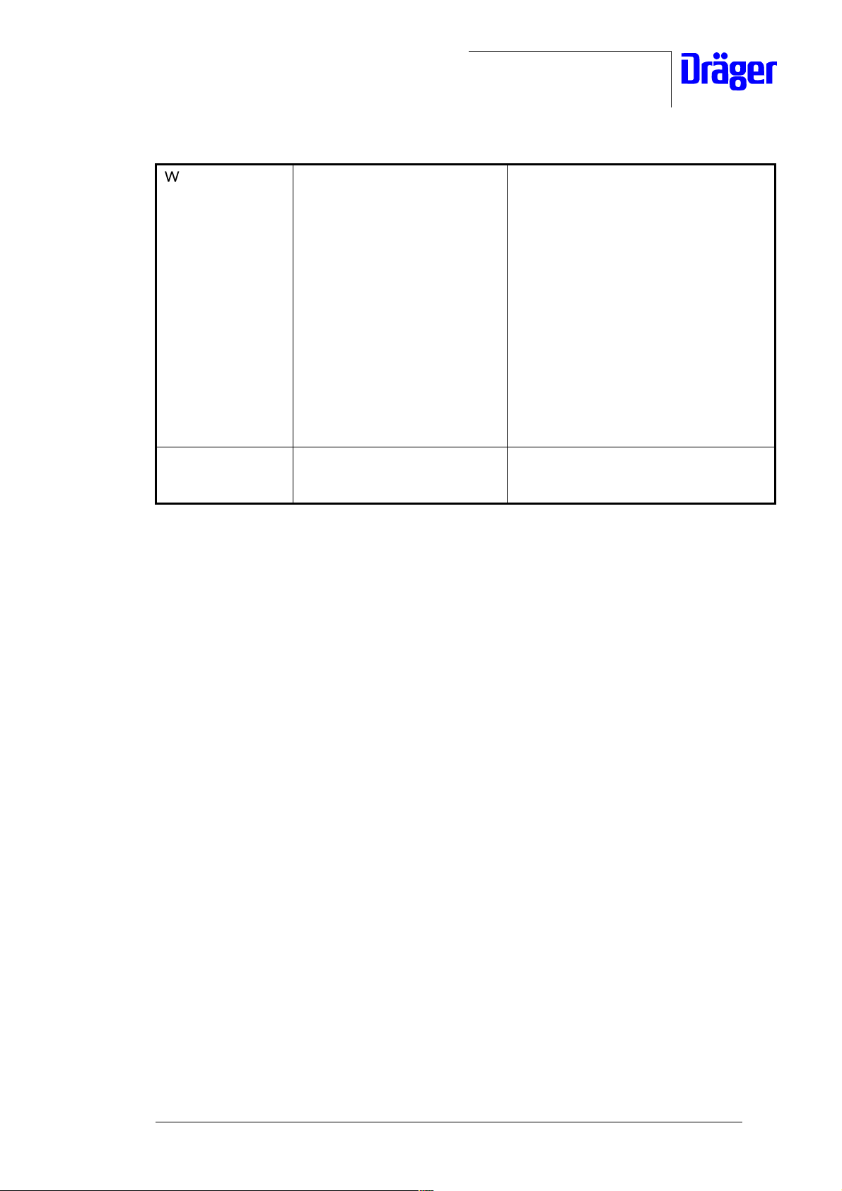
Table 1: Service Strategy
Dräger Medizintechnik
Workshop in
Lübeck
Customer, owner,
user
− Test Certificate
− Spare parts list
− Microfiche chapter “R”
− Repair instructions
− Service Bulletins (IDM)
− Conversion instructions
− Process and inspection
instructions
− Circuit diagrams
− Function schematics
− Instructions for Use
− Check list, if applicable
− Replacing all electrical, electronic
and mechanical assemblies
− Settings, calibrations
− Complex conversions
− Recording the actual condition of
the device
For internal use only. Copyright reserved.
R6132300T01.fm 26.07.00
6132.300 Babytherm 8004/8010 05/2000 Repair Instructions Page 6
Dräger Medizintechnik
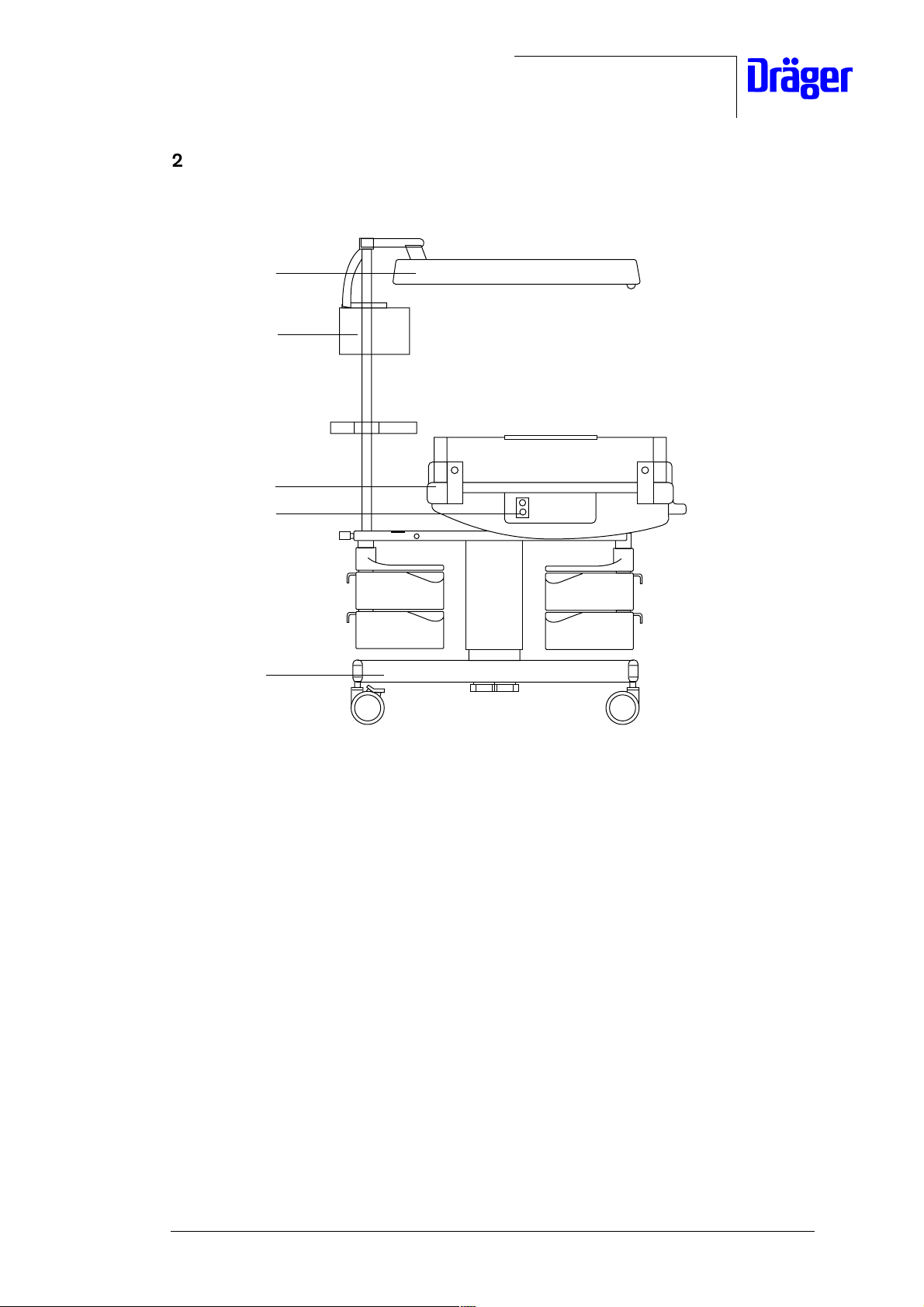
2 Babytherm 8004/8010 Assemblies
1
2
3
4
5
Fig. 1: Front view of the Babytherm 8010
Legend
1Radiant heater
2 Control unit
3 Resting surface:
− with skin temperature control (Babytherm 8004)
− with skin temperature control and mattress heater (Babytherm 8010)
4 Skin temperature sensor connection port (Babytherm 8004/Babytherm 8010)
5Trolley:
− with fixed column
− with electrical height adjustment (optional)
For internal use only. Copyright reserved.
R6132300T01.fm 26.07.00
6132.300 Babytherm 8004/8010 05/2000 Repair Instructions Page 7
Dräger Medizintechnik
3Radiant Heater
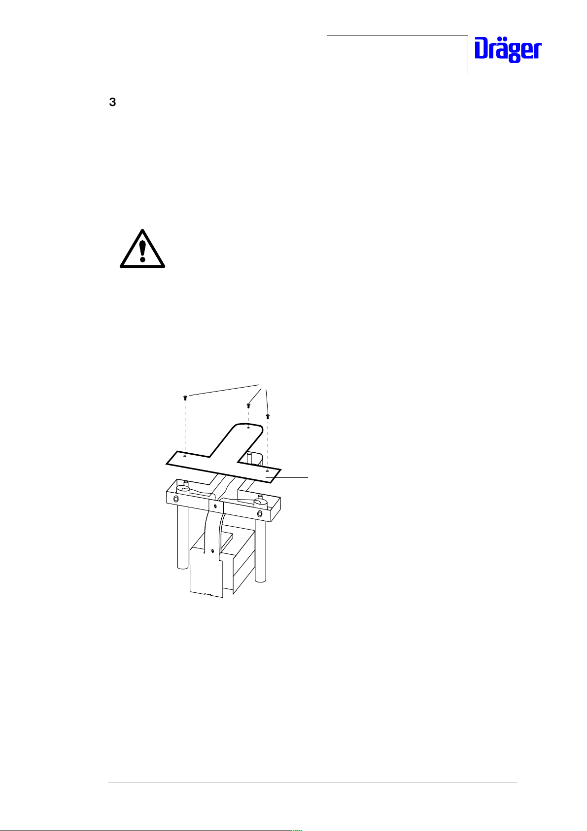
3.1 Dismounting the Radiant Heater from the Trolley
• Set the electrical height adjustment (optional) of the Babytherm to the lowest position.
• Unplug the Babytherm power cord from the mains socket-outlet.
Hot parts! The halogen lamps or infrared rods may cause burns if
touched shortly after use of the radiant heater.
Allow the radiant heater to cool off for at least 15 minutes before
servicing.
• Swivel the radiant heater in your direction.
• Remove the fixing screws 1 from the T-cover plate 2.
• Place the T-cover plate 2 aside.
1
2
Fig. 2: Top view of the Babytherm, removing the T-cover plate
For internal use only. Copyright reserved.
R6132300T01.fm 26.07.00
6132.300 Babytherm 8004/8010 05/2000 Repair Instructions Page 8
Dräger Medizintechnik
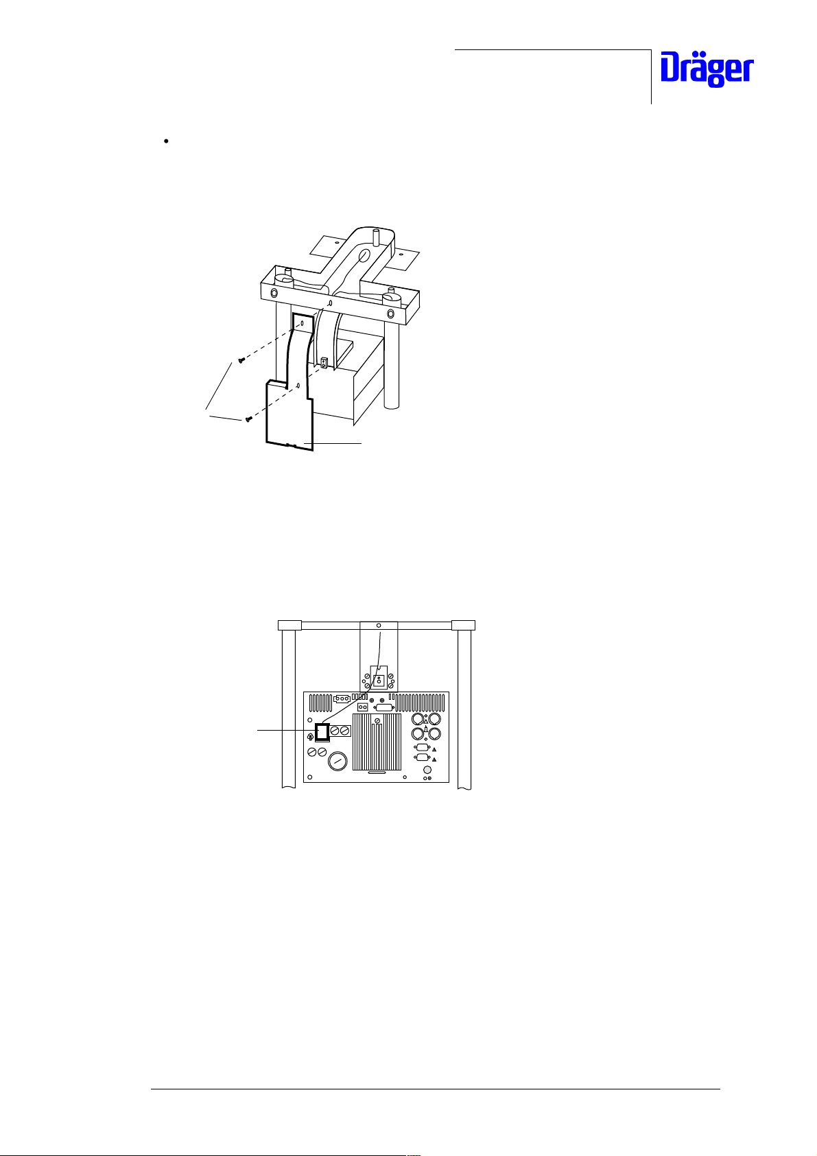
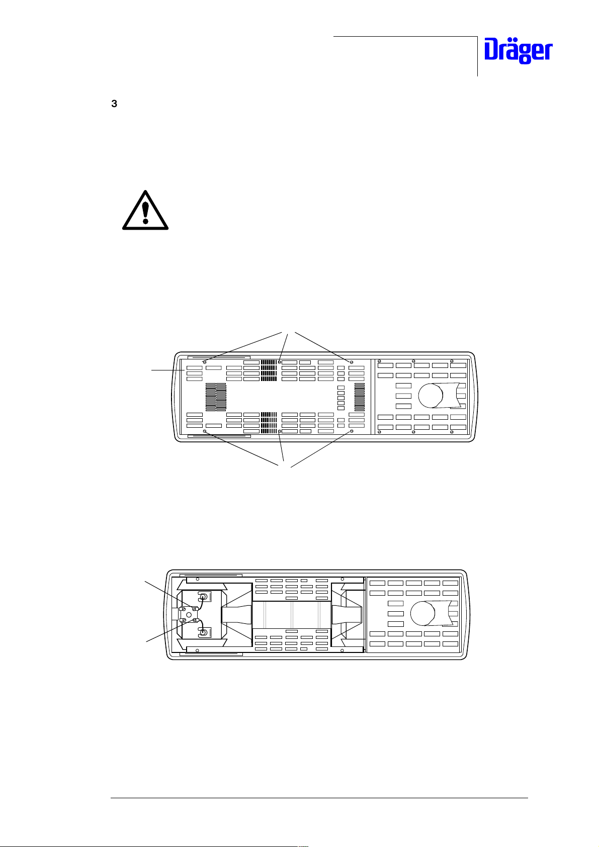
• Remove the fixing screws 3 from the protective cover support 4.
• Place the protective cover support 2 aside.
3
4
Fig. 3: Top view of the Babytherm, removing the protective cover support
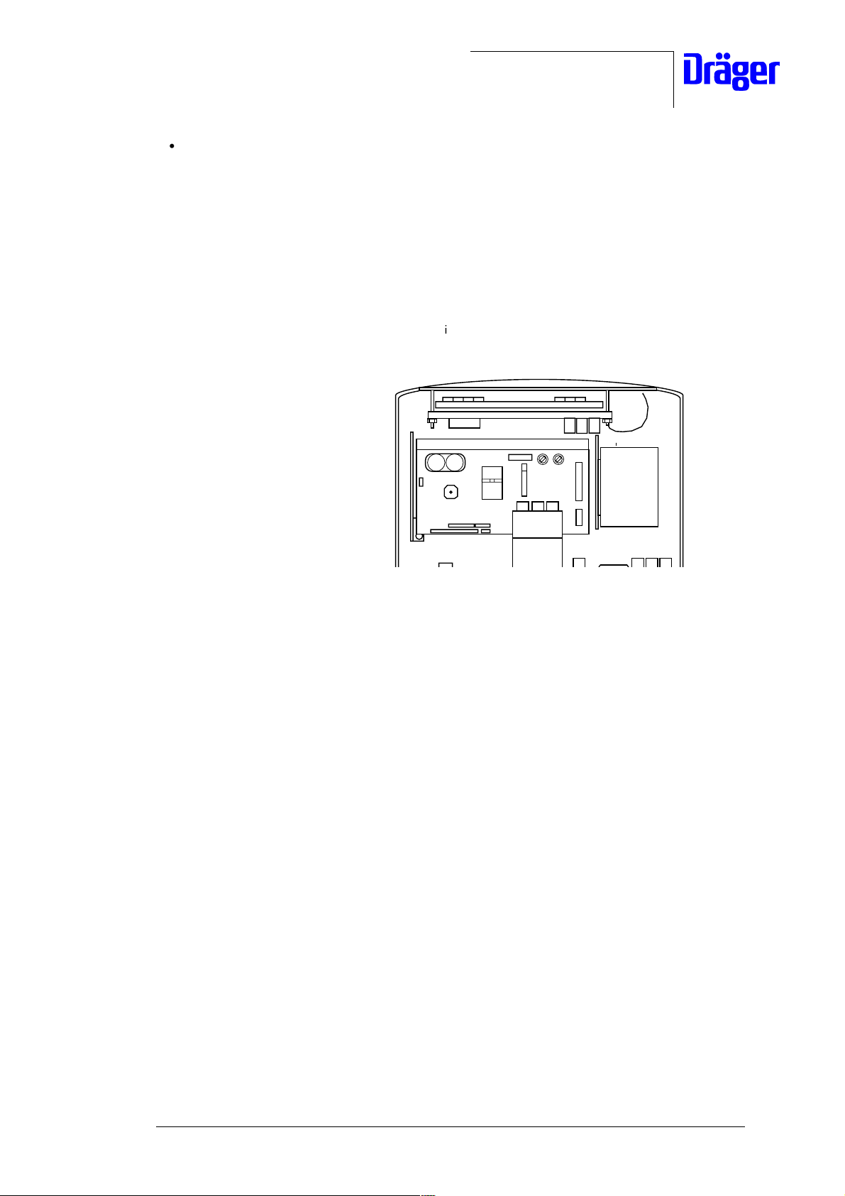
• Disconnect the cable connector 5 from the control unit.
5
Fig. 4: Rear view of the control unit, disconnecting the cable connector
For internal use only. Copyright reserved.
R6132300T01.fm 26.07.00
6132.300 Babytherm 8004/8010 05/2000 Repair Instructions Page 9
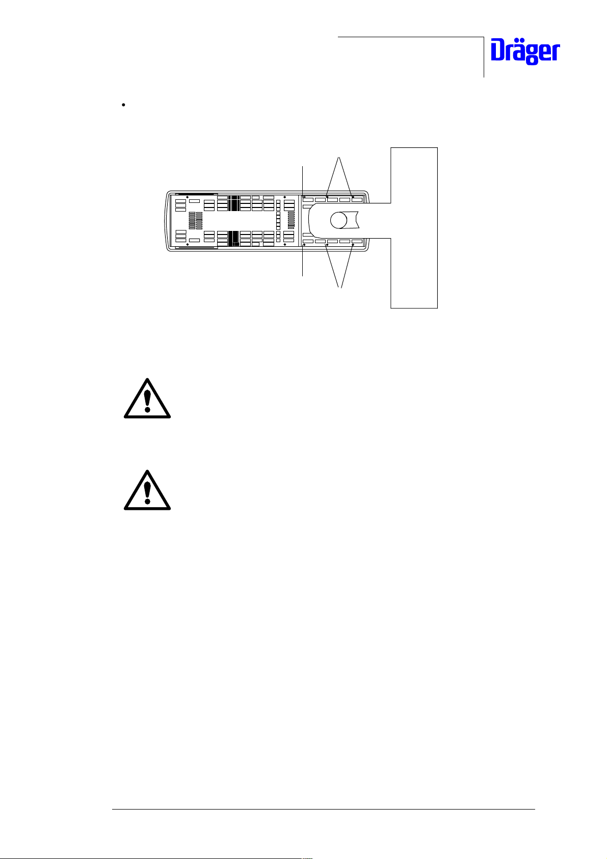
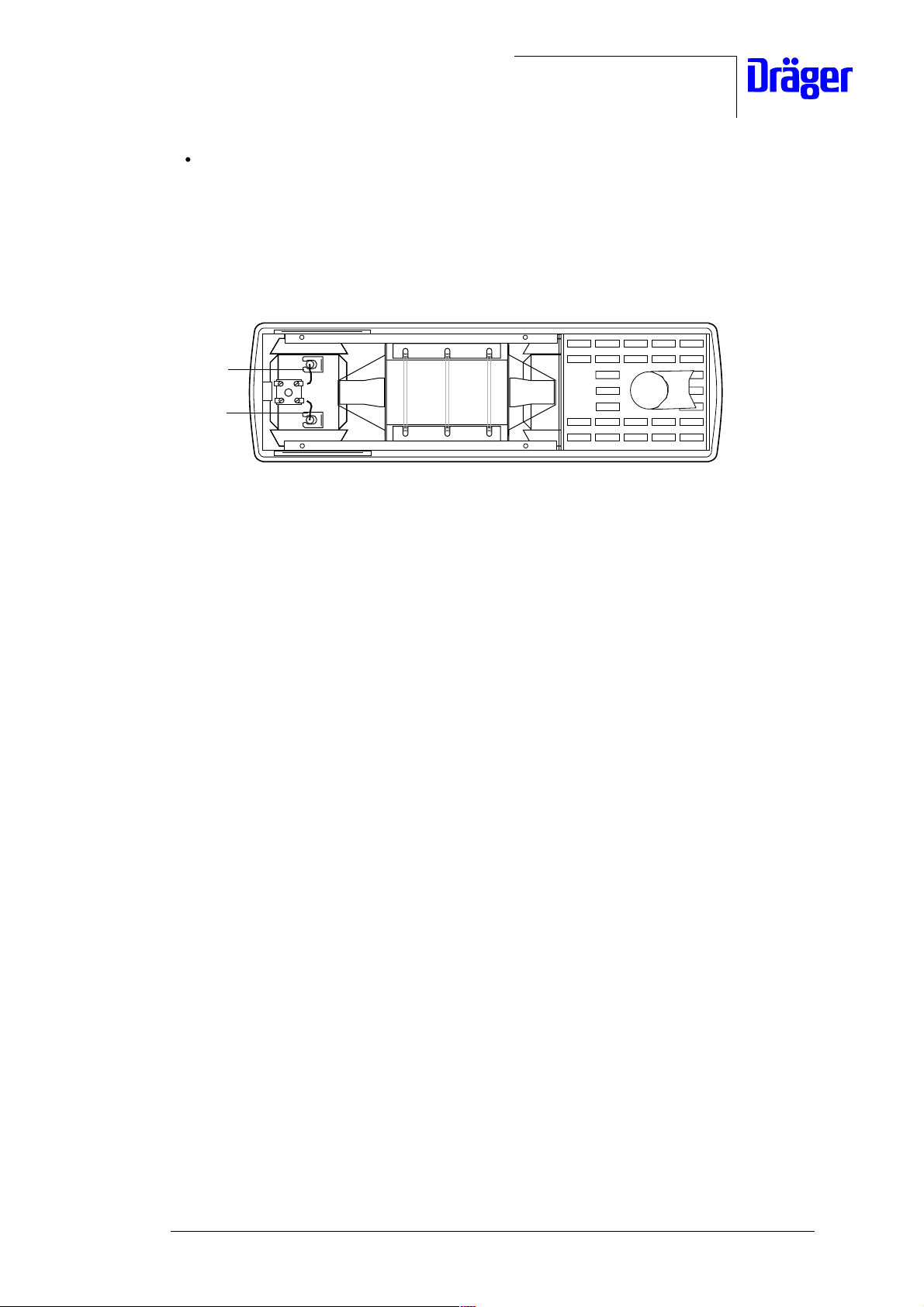
• Remove the fixing screws and washers 6.
Dräger Medizintechnik
7
7
Fig. 5: Top view of the Babytherm 8004/8010
Risk of personal injury! Removing all fixing screws will detach the
radiant heater from the trolley causing it to fall. To avoid personal injury
support the radiant heater with one arm while removing the fixing
screws.
6
6
Risk of damage! Removing all fixing screws will detach the radiant
heater from the trolley causing it to fall. To avoid damage to the radiant
heater support it with one arm while removing the fixing screws.
• Remove the fixing screws and washers 7 from the radiant heater (see Fig. above) and
carefully thread the disconnected cable of the control unit through the articulated joint.
• Place the defective radiant heater aside.
• Mount the new radiant heater onto the Babytherm trolley using the reverse method of
that used for dismounting the defective radiant heater.
• Mount the protective cover support onto the control unit.
• Mount the T-cover plate onto the trolley.
• Perform a function test on the radiant heater, see "Test Certificate".
For internal use only. Copyright reserved.
R6132300T01.fm 26.07.00
6132.300 Babytherm 8004/8010 05/2000 Repair Instructions Page 10
Dräger Medizintechnik
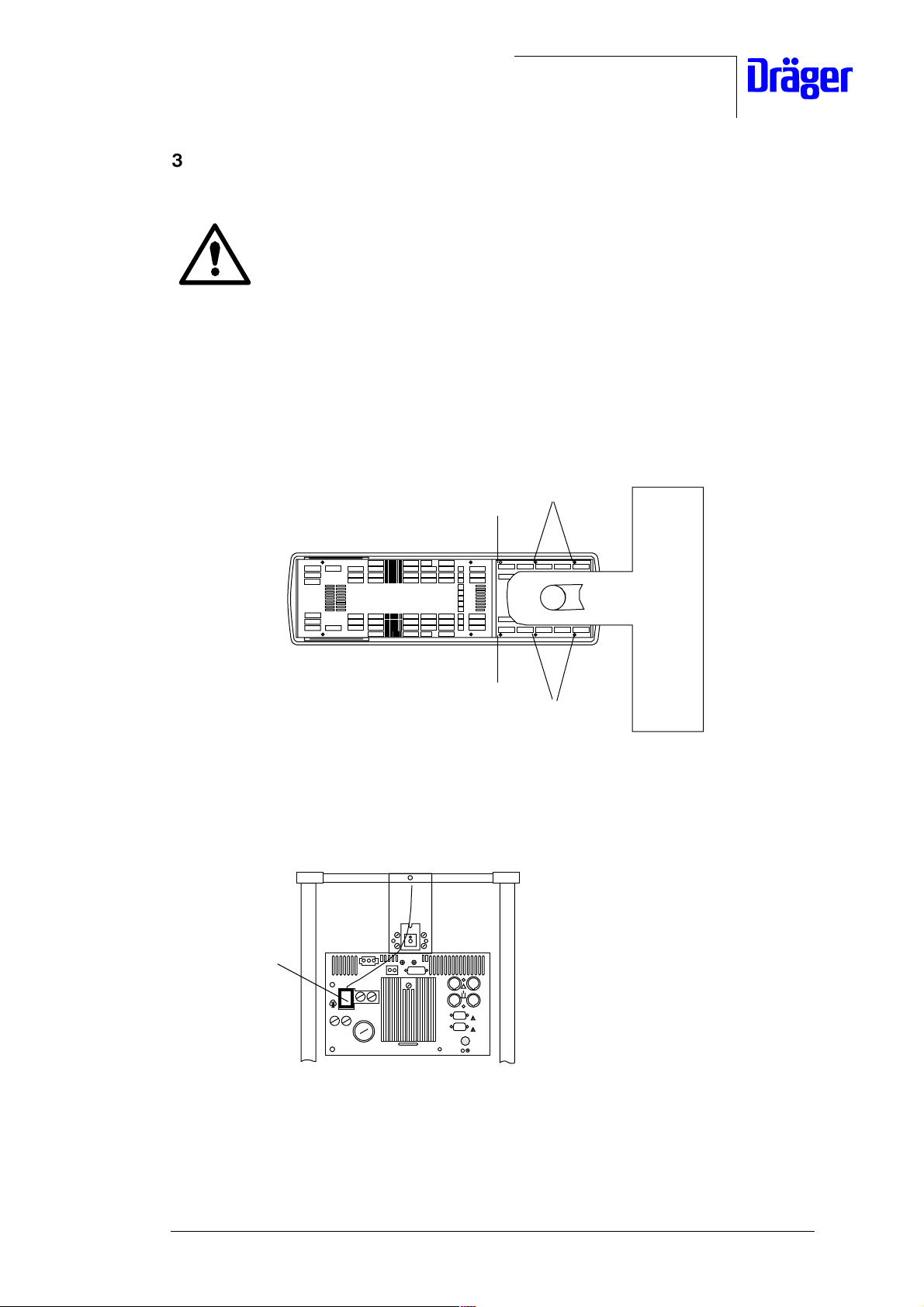
3.2 Mounting the Radiant Heater to the Trolley
Risk of personal injury. The radiant heater is heavy and may fall down when
mounted to the trolley by one person only. To avoid this, mount the radiant
heater to the trolley with the help of a second person.
• Mount the radiant heater to the trolley. To do so, thread the cable protruding from the
radiant heater through the articulated joint and secure the radiant heater to the trolley
using the fixing screws and washers 1. (Note: The tightening torque for the fixing screws
is 3 +0,5 Nm.)
• Secure the fixing screws 1 with Loctite 221.
1
1
Fig. 6: Babytherm (top view)
• Connect the cable connector 2 to the control unit.
1
1
2
Fig. 7: Control unit (rear view); connecting the cable connector
For internal use only. Copyright reserved.
R6132300T01.fm 26.07.00
6132.300 Babytherm 8004/8010 05/2000 Repair Instructions Page 11
Dräger Medizintechnik
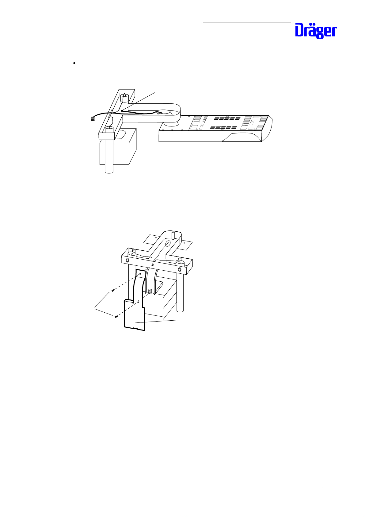
• Mount the grounding cable using the fixing screw and spring washer 1.
1
Fig. 8: Side view of the T-piece, mounting the grounding cable
• Secure the protective cover support using the fixing screws 2.
2
Protective cover suppor t
Fig. 9: Babytherm (top view); mounting the protective cover support
For internal use only. Copyright reserved.
R6132300T01.fm 26.07.00
6132.300 Babytherm 8004/8010 05/2000 Repair Instructions Page 12
Dräger Medizintechnik
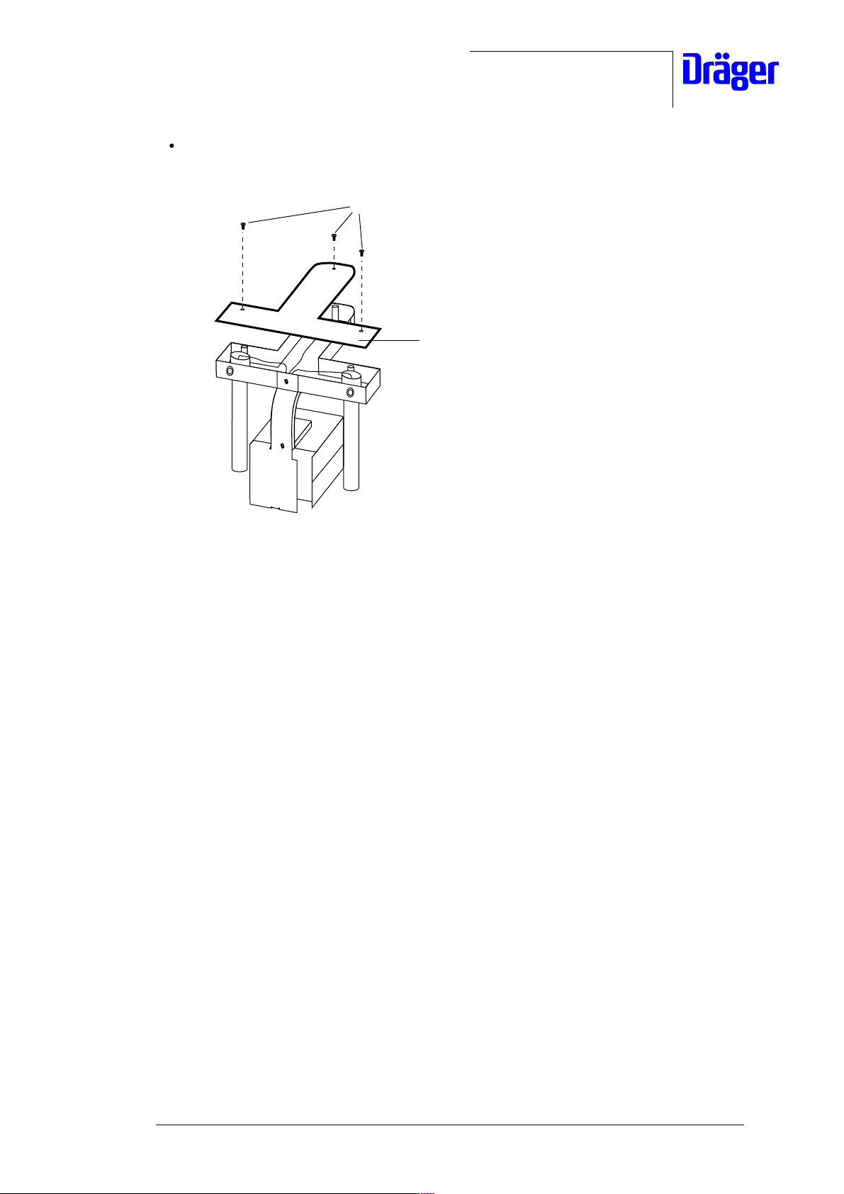
• Mount the T-cover plate 2 to the trolley using the fixing screws 3.
3
2
Fig. 10: Babytherm (top view); mounting the T-cover plate
• Test the function of the radiant heater, see "Test Certificate".
For internal use only. Copyright reserved.
R6132300T01.fm 26.07.00
6132.300 Babytherm 8004/8010 05/2000 Repair Instructions Page 13
Dräger Medizintechnik
3.3 Infrared Rods
3.3.1 General Information About the Infrared Rods
If the infrared rods of the radiant heater are defective they must be replaced.
3.3.2 Checking the Infrared Rods
• Press the “skin/man” key and activate the “man” function.
• Press the OK key.
• Use the arrow keys to adjust heating level “1”.
The desired heating level “1” is indicated by one bar LED on the 8004/8010 control unit.
The infrared rods of the radiant heater radiate a lower amount of heat (to check, hold open
hands at approx. 30 cm from the infrared rods).
• Use the arrow keys to adjust heating level “6”.
The desired heating level “6” is indicated by six bar LEDs on the 8004/8010 control unit. The
infrared rods of the radiant heater radiate a higher amount of heat (to check, hold open
hands at approx. 30 cm from the infrared rods).
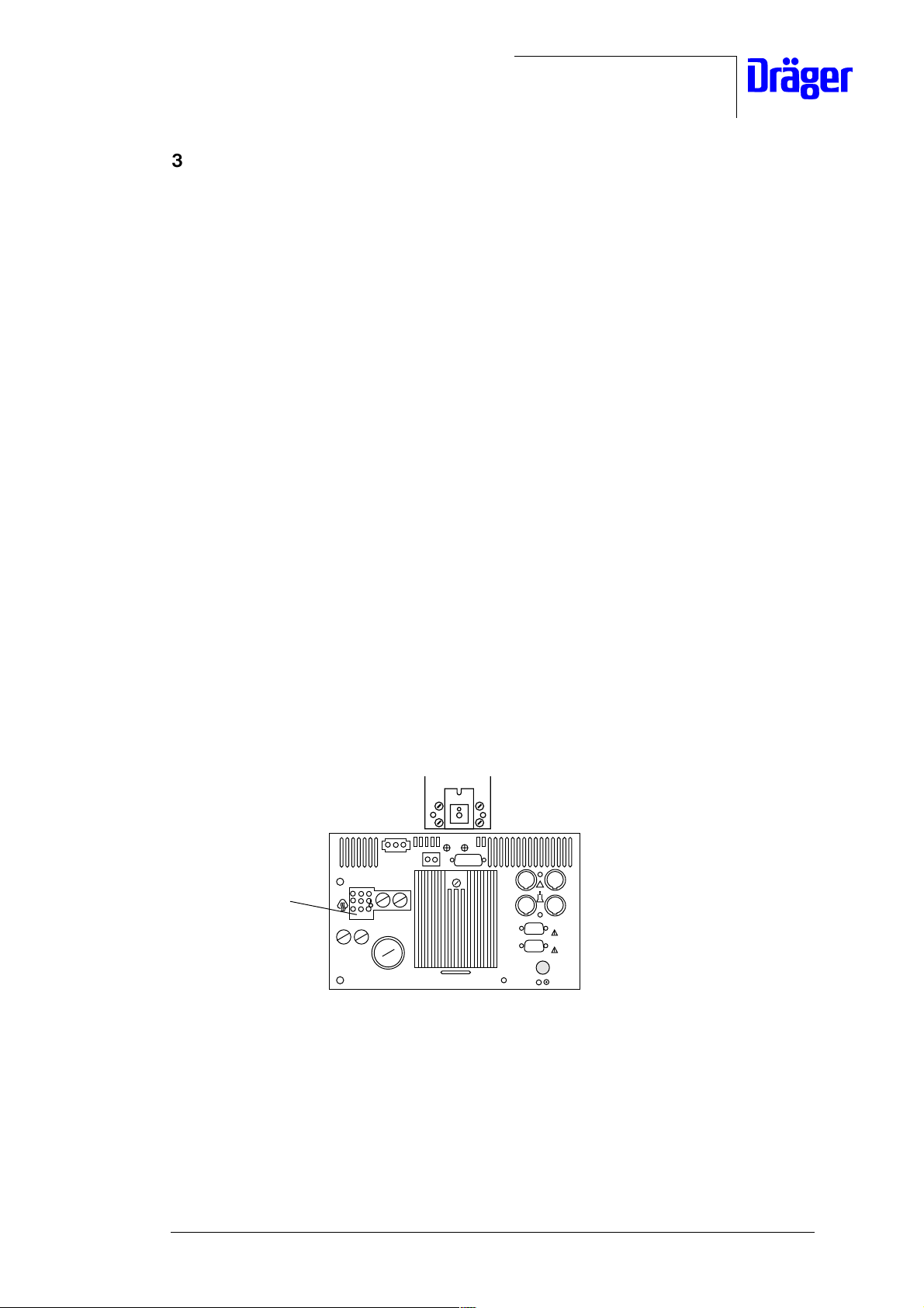
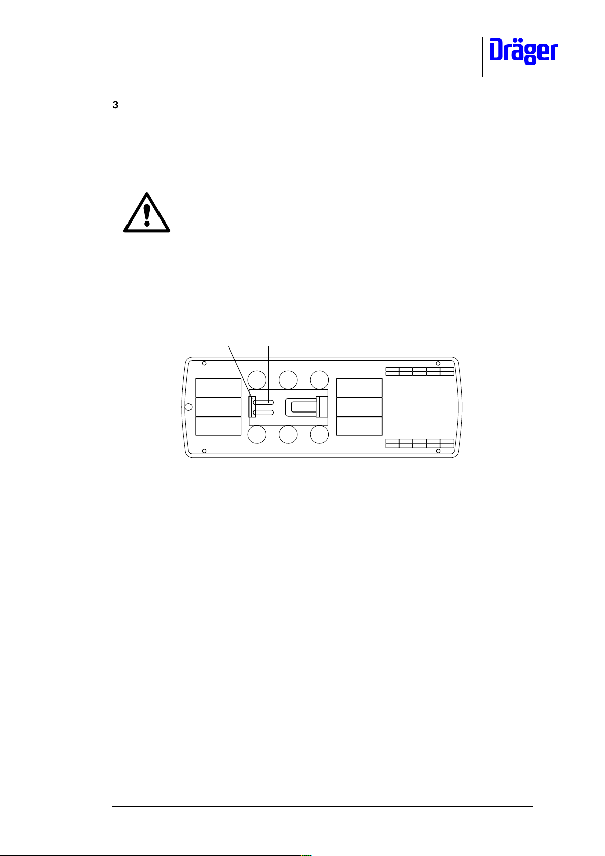
3.3.3 Checking the Infrared Rods with an Ohmmeter
• Disconnect cable connector 1 from the control unit.
1
Fig. 11: Rear view of the control unit
For internal use only. Copyright reserved.
R6132300T01.fm 26.07.00
6132.300 Babytherm 8004/8010 05/2000 Repair Instructions Page 14
Dräger Medizintechnik
• Connect test probes of ohmmeter to pin contacts 1 and 2 of the cable connector.
The measured resistance should be approx. 86 ohms.
infrared rods
1
Fig. 12: Cable connector pins
2
For internal use only. Copyright reserved.
R6132300T01.fm 26.07.00
6132.300 Babytherm 8004/8010 05/2000 Repair Instructions Page 15
Dräger Medizintechnik
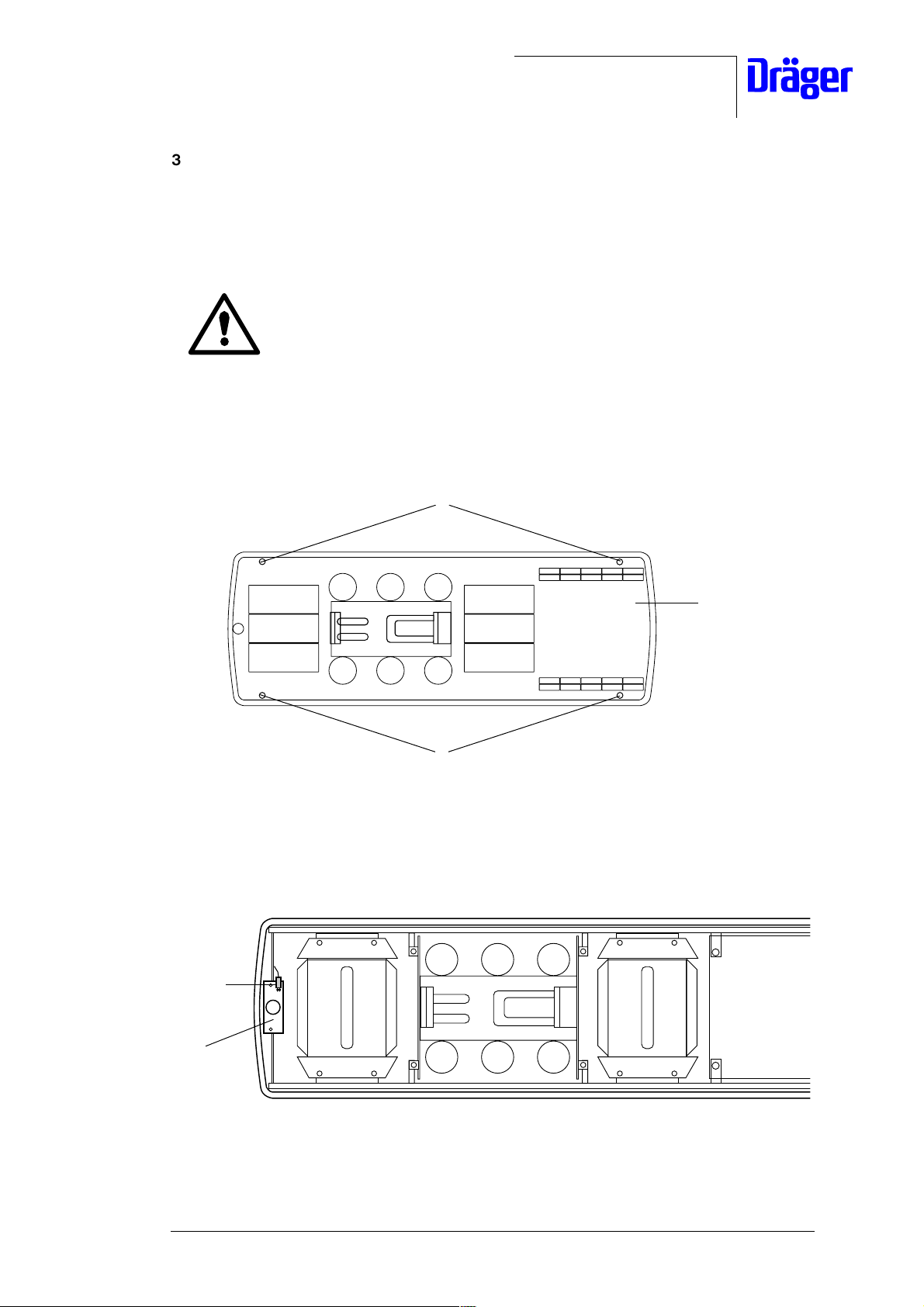
3.3.4 Replacing an Infrared Rod
• Set the electrical height adjustment (optional) of the Babytherm to the lowest position.
• Unplug the Babytherm power cord from the mains socket-outlet.
Hot parts! The halogen lamps or infrared rods may cause burns if
touched shortly after use of the radiant heater.
Allow the radiant heater to cool off for at least 15 minutes before
servicing.
• Swivel the radiant heater in your direction.
• Remove the screws and washers 1 from the cover 2 and place the cover 2 aside.
1
2
1
Fig. 13: Top view of the radiant heater, removing the cover
• Disconnect the cables of the defective infrared rod from the terminals 3.
3
3
Fig. 14: Top view of the radiant heater, disconnecting the cables
For internal use only. Copyright reserved.
R6132300T01.fm 26.07.00
6132.300 Babytherm 8004/8010 05/2000 Repair Instructions Page 16
Dräger Medizintechnik
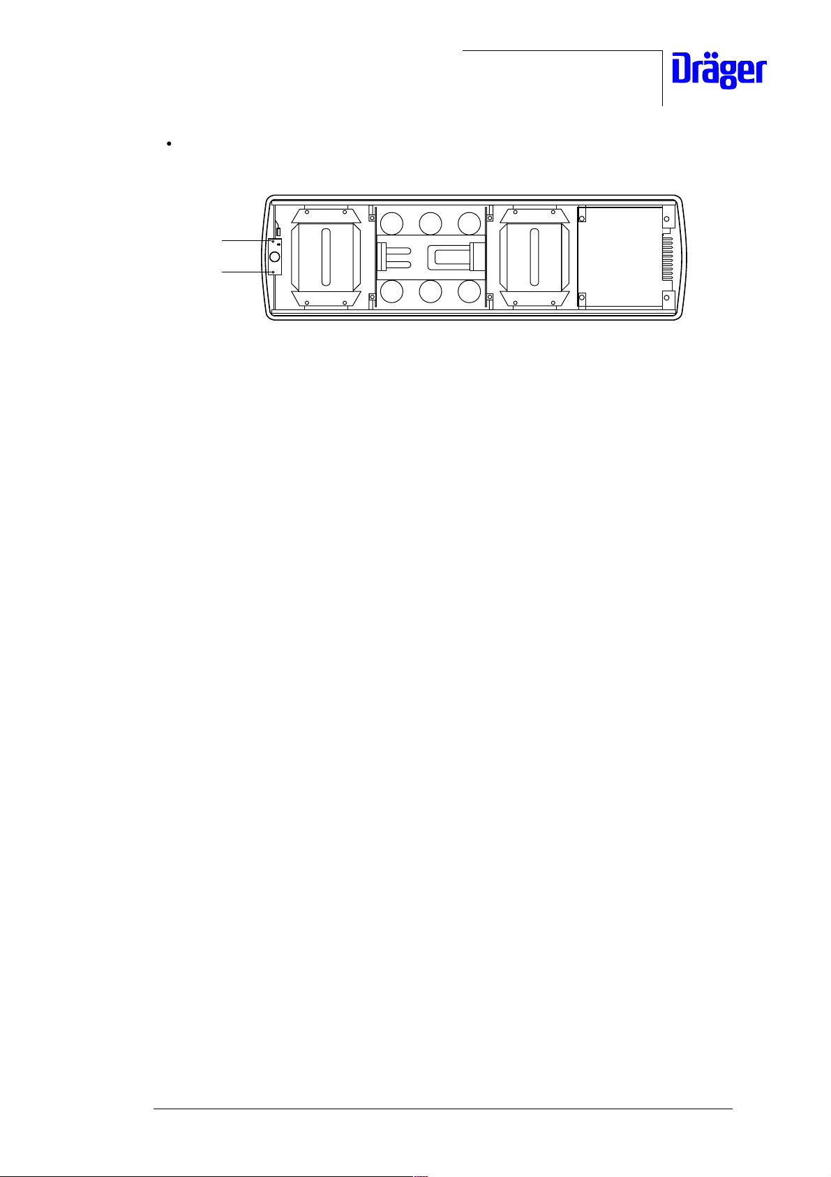
• Hold the defective infrared rod from the underside and remove the clamps 4 by pushing
them aside.
• Thread the cables of the defective infrared rod through the holes of the radiant heater
and pull the defective infrared rod down and out of the radiant heater.
• Dispose of the defective infrared rod according to local waste disposal regulations.
4
4
Fig. 15: Top view of the radiant heater, removing the clamps
• Mount the new infrared rod using the reverse method of that used for dismounting the
defective infrared rod.
• Perform a function test on the infrared rod, see "Checking the Infrared Rods".
• Check Babytherm using the Test Certificate, see "Test Certificate".
For internal use only. Copyright reserved.
R6132300T01.fm 26.07.00
6132.300 Babytherm 8004/8010 05/2000 Repair Instructions Page 17

Dräger Medizintechnik
3.4 Work Light/Night Light
3.4.1 General Information About the Work Light/Night Light
The work light or the night light of the radiant heater must be replaced if they are defective.
3.4.2 Checking the Work Light
• Plug the Babytherm power cord into the mains socket outlet.
• Switch on the Babytherm.
• Press the work light key.
The energy-saving lamps of the radiant heater are switched on.
• Press the work light key again.
The energy-saving lamps of the radiant heater are switched off.
3.4.3 Checking the Night Light
• Plug the Babytherm power cord into the mains socket outlet.
• Switch on the Babytherm.
• Press the night light key.
The small energy-saving lamp of the radiant heater is switched on.
• Press the night light key again.
The small energy-saving lamp of the radiant heater is switched off.
For internal use only. Copyright reserved.
R6132300T01.fm 26.07.00
6132.300 Babytherm 8004/8010 05/2000 Repair Instructions Page 18
Dräger Medizintechnik
3.4.4 Replacing the Night Light
• Set the electrical height adjustment (optional) of the Babytherm to the lowest position.
• Unplug the Babytherm power cord from the mains socket-outlet.
Hot parts! The halogen lamps or infrared rods may cause burns if
touched shortly after use of the radiant heater. Allow the radiant heater
to cool off for at least 15 minutes before servicing.
• Swivel the radiant heater in your direction.
• Remove the defective energy-saving lamp 1 (night light) by holding the lamp mount 2
and by turning the energy-saving lamp counter-clockwise.
2
Fig. 16: View on the actuators of the radiant heater, removing the night light
• To mount the new energy-saving lamp 1 (night light) hold the lamp mount 2 and tighten
the energy-saving lamp by turning it clockwise.
• Mount the Babytherm using the reverse method of that used for dismounting.
• Plug the Babytherm power cord into the mains socket outlet.
• Check the function of the energy-saving lamp 1 (night light) by pressing the night light
key.
1
The night light of the radiant heater should come on.
• Check Babytherm using the Test Certificate, see "Test Certificate".
For internal use only. Copyright reserved.
R6132300T01.fm 26.07.00
6132.300 Babytherm 8004/8010 05/2000 Repair Instructions Page 19

Dräger Medizintechnik
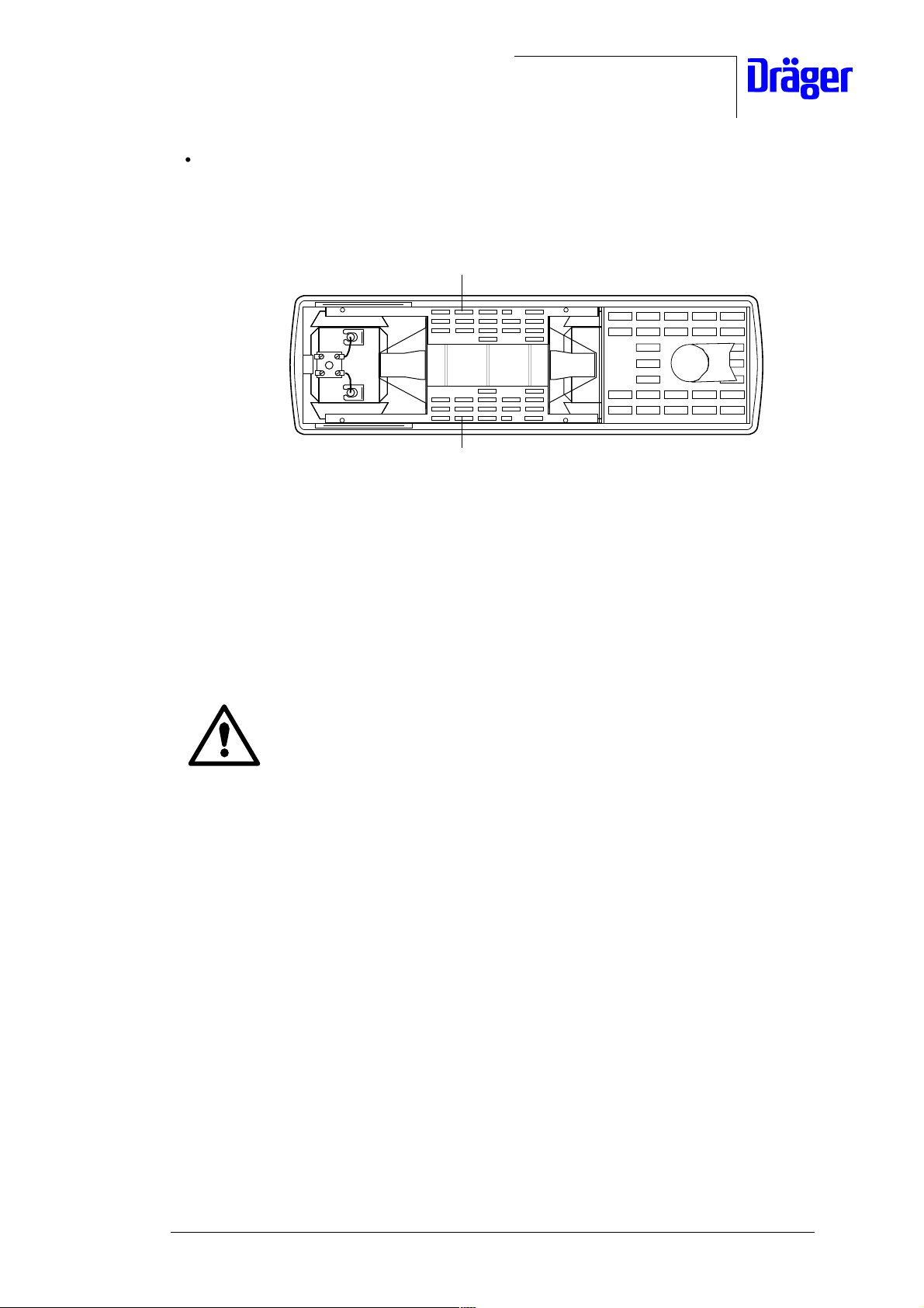
3.4.5 Replacing the Work Light
• Set the electrical height adjustment (optional) of the Babytherm to the lowest position.
• Unplug the Babytherm power cord from the mains socket-outlet.
Hot parts! The halogen lamps or infrared rods may cause burns if
touched shortly after use of the radiant heater. Allow the radiant heater
to cool off for at least 15 minutes before servicing.
• Swivel the radiant heater in your direction.
• Remove the defective energy-saving lamp 1 (work light) by holding the lamp mount 2
and by turning the energy-saving lamp 1 counter-clockwise.
1
Fig. 17: Bottom view of the radiant heater, dismounting the work light
• To mount the new energy-saving lamp 1 (work light) hold the lamp mount 2 and tighten
the energy-saving lamp by turning it clockwise.
• Mount the Babytherm using the reverse method of that used for dismounting.
• Plug the Babytherm power cord into the mains socket outlet.
• Check the function of the energy-saving lamp 1 (work light) by pressing the work light
key.
Both energy-saving lamps of the radiant heater should come on.
2
• Check Babytherm using the Test Certificate, see "Test Certificate".
For internal use only. Copyright reserved.
R6132300T01.fm 26.07.00
6132.300 Babytherm 8004/8010 05/2000 Repair Instructions Page 20

Dräger Medizintechnik
3.5 Central Alarm PCB
3.5.1 General Information About the Central Alarm PCB
If the Central Alarm PCB is defective, it should be replaced completely.
3.5.2 Checking the Central Alarm PCB
• Plug the Babytherm power cord into the mains socket outlet.
• Switch on the Babytherm.
• Press the Check key.
The central alarm lamp (located on the Central Alarm PCB) should flash.
For internal use only. Copyright reserved.
R6132300T01.fm 26.07.00
6132.300 Babytherm 8004/8010 05/2000 Repair Instructions Page 21
Dräger Medizintechnik
3.5.3 Replacing the Central Alarm PCB
• Set the electrical height adjustment (optional) of the Babytherm to the lowest position.
• Unplug the Babytherm power cord from the mains socket-outlet.
Hot parts! The halogen lamps or infrared rods may cause burns if
touched shortly after use of the radiant heater. Allow the radiant heater
to cool off for at least 15 minutes before servicing.
• Swivel the radiant heater in your direction.
•Remove the screws and washers 1 of the cover 2 and place the cover 2 aside.
1
1
Fig. 18: Bottom view of the radiant heater, removing the cover
• Disconnect the connector 3 from the Central Alarm PCB 4.
3
2
4
Fig. 19: Bottom view of the radiant heater, removing the connector
For internal use only. Copyright reserved.
R6132300T01.fm 26.07.00
6132.300 Babytherm 8004/8010 05/2000 Repair Instructions Page 22
Dräger Medizintechnik
• Compress the printed circuit board mount 1 and remove the Central Alarm PCB.
1
1
Fig. 20: Bottom view of the radiant heater, removing the Central Alarm PCB
• Replace the defective Central Alarm PCB with a new one.
• Mount the radiant heater using the reverse method of that used for dismounting.
• Connect the Babytherm power cord into the mains socket outlet.
• Switch on the Babytherm.
• Press the Check key.
The central alarm lamp (located on the Central Alarm PCB) should flash.
• Check Babytherm using the Test Certificate, see "Test Certificate".
For internal use only. Copyright reserved.
R6132300T01.fm 26.07.00
6132.300 Babytherm 8004/8010 05/2000 Repair Instructions Page 23

Dräger Medizintechnik
3.6 Phototherapy (Optional)
The phototherapy of the radiant heater consists of the following assemblies:
− Switched-Mode Power Supply PCB;
− six halogen lamps;
− two thermostats.
The thermostats of the phototherapy are connected in series with the halogen lamps. If one
thermostat is defective, it will not be possible to switch on the phototherapy (halogen lamps).
3.6.1 General Information About the Halogen Lamps
The complete set of halogen lamps should be replaced after 1000 operating hours or in the
event of a failure.
Two halogen lamps each are connected in series. Therefore, if one
halogen lamp fails, the other one of the respective pair will not come on
either.
3.6.2 Checking the Halogen lamps
• Plug the Babytherm power cord into the mains socket outlet.
• Switch on the Babytherm.
• Press the phototherapy key on the control unit.
• Press the OK key.
All halogen lamps in the radiant heater come on.
• Press the phototherapy key again.
• Press the OK key.
All halogen lamps in the radiant heater go out.
• Check Babytherm using the Test Certificate, see "Test Certificate".
For internal use only. Copyright reserved.
R6132300T01.fm 26.07.00
6132.300 Babytherm 8004/8010 05/2000 Repair Instructions Page 24
Dräger Medizintechnik
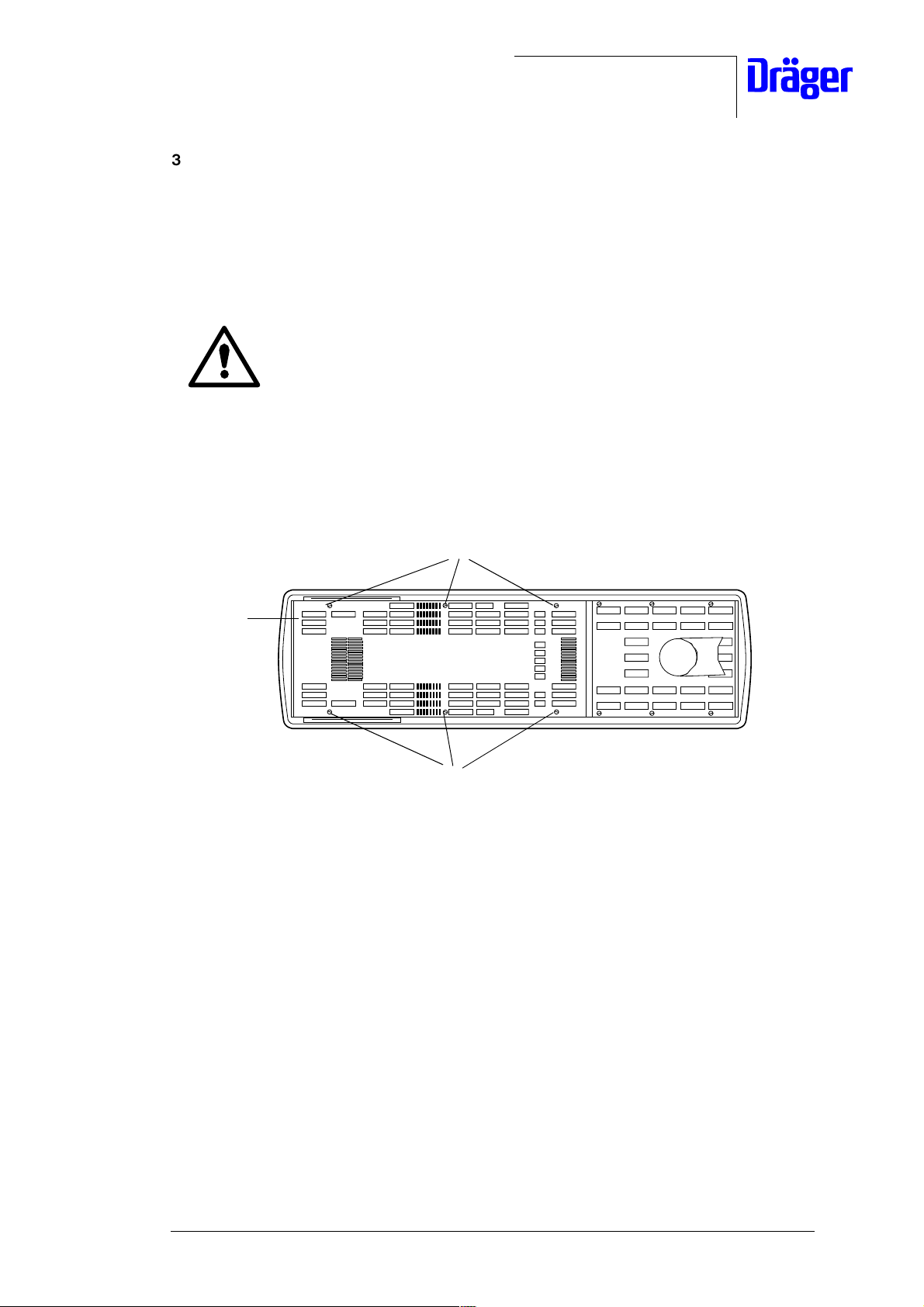
3.6.3 Checking the Thermostat
• Set the electrical height adjustment (optional) of the Babytherm to the lowest position.
• Switch off the Babytherm.
• Unplug the Babytherm power cord from the mains socket-outlet.
Hot parts! The halogen lamps or infrared rods may cause burns if touched
shor tly af ter use of the radiant heater. Allow the radiant heater to cool off
for at least 15 minutes before servicing.
• Swivel the radiant heater in your direction.
• Remove the fixing screws and washers 1 which secure the cover 2 and place the cover
aside.
1
2
1
Fig. 21: Top view of the radiant heater, removing the fixing screws
For internal use only. Copyright reserved.
R6132300T01.fm 26.07.00
6132.300 Babytherm 8004/8010 05/2000 Repair Instructions Page 25
Dräger Medizintechnik
• Measure the contact resistance of thermostat 1.
The contact resistance of the thermostat should be approx. 0 ohms.
1
1
Fig. 22: Top view of the radiant heater, mounting position of the thermostat
If the thermostat has an infinite contact resistance, it is defective.
• Replace the defective thermostat with a new one.
• Make sure that the protective screen which cover the thermostats has not been pushed
into the radiant heater.
The clearance of the protective screen to the terminals of the
thermostats must be at least 2.5 mm.
• Secure the cover to the radiant heater using fixing screws and washers.
• Plug the Babytherm power cord into the mains socket-outlet.
• Switch on the Babytherm.
• Press the phototherapy key.
All halogen lamps in the radiant heater should come on.
• Perform a leakage current measurement using the Test Certificate, see "Test
Certificate".
For internal use only. Copyright reserved.
R6132300T01.fm 26.07.00
6132.300 Babytherm 8004/8010 05/2000 Repair Instructions Page 26
 Loading...