

Drager Babytherm 8004, Babytherm 8010 Service Manual
Test Certificate
Babytherm
DrägerService
Explanation of Symbols
OK C = Check condition
8004/8010
Installation site:
File no.:
Edition
6132.300
01.2003
Defect/error/fault O = Check function
Spare parts used L = Check for leaks
Report V = Enter value
Accessories missing
∩
For internal use only. For internal use only.
1. Device in general
1.1 Software version
1.2 Options as per name plate
1.3 Operating hours
Serial no.:
Date of delivery/
startup:
Invoice no. or
delivery no.:
Other:
1.4 General condition
1.4.1 Connecting cable of Babytherm
1.4.2 Connecting cable of the column (US version)
Connecting cable of column is
undamaged.
1.4.3 Control unit
1.4.3.1 Attachment
1.4.3.2 Fuses
The fuses are as specified on the rating
plate.
1.4.3.3 Membrane keypad
1.4.3.4 ON/OFF switch
1.4.3.5 Plug-in connector
C
C
C
C
C
C
C
1/17
1.4.4 Mains voltage distributor (located underneath base plate)
The fuses are as specified on the rating
plate.
1.4.5 Trolley and column
C
1.4.5.1 Pedals of height adjustment (optional)
1.4.5.2 2 x castor 125 mm (2M 20792)
1.4.5.3 2 x lockable castor 125 mm (2M 20794)
1.4.5.4 4 x cap (2M 20348) on tube ends of trolley. The cap holds the castors.
1.4.6 Mattress heater
1.4.6.1 Sealing of heating plate
1.4.7 Mattress
1.4.7.1 Foam mattress, Babytherm 8004
(2M 21012).
1.4.7.2 Gel mattress, Babytherm 8010 (2M
20827)
Important: Repair small fissures on
surface using adhesive tape or repair set
for gel mattress 2M 21324.
1.4.8 Hook rail with hook 2 M 21293 beneath the top part of the mattress tray (option)
C
C
C
C
C
C
C
C
1.4.9 Grip strip 2M 21468 on top part of mattress tray (option)
1.4.10 Canopy 2M 21030 (option)
1.4.10.1 Thermometer 2M11111
Comparative measurement in water bath,
permissible deviation 0.4 °C, water bath
20 – 35 °C.
1.4.10.2 Holder for canopy (2M 21342)
1.4.11 Bottom part of mattress tray
The bottom part of the mattress tray is
secured to the base plate with 4 Allen
screws.
1.4.12 Bottom part of mattress tray
1.4.12.1 Corners 2M 21390 for mounting of panel.
1.4.12.2 Panels, 4 x (15 cm or 23 cm height)
The panels engage securely in the
corners.
C
CO
O
C
C
C
CO
2/17
1.4.12.3 Hose ducts (2M 20434)
1.4.12.4 Only with 23 cm face panel at the rear:
Lock (2M 13042)
Injector (2M 14190)
Label with flow table (2M 21147)
1.4.13 Inside panel 2 M 20936 (height approx. 70 mm)
1.4.14 Mattress tray tilt adjustment
1.4.14.1 Resetting springs (8300445)
Resetting springs for locking lever are
fitted.
C
C
C
C
1.4.15 X-ray drawer (Babytherm 8004, option)
1.4.16 Core and peripheral skin-temperature sensor connector
1.4.17 Protective screen (radiant heater)
1.4.18 Suction
1.4.18.1 Replace bacterial filter CH 102.
1.4.19 Grip strip accessory rail (2M 20860)
1.4.20 Swivel cupboard with attachment (option)
1.4.21 Stand.
1.4.22 Tray for monitor
1.4.23 Rail for tray
1.4.24 Compact rail 2M 85337 (option)
*
(set of 5 6723976)
Retighten screws of stand.
C
C
C
C
C
C O
C
C
C
C
1.4.25 Carrying frame (M 25858)
1.4.25.1 Jar holder
1.4.26 Connecting hose
1.4.27 Secretion suction hose (M 25780)
1.4.28 Secretion sightglass or finger tip (M
07582)
1.4.29 Container, 2 x (M 20091)
1.4.30 Cylinder cap 2M 85012 with valve
1.4.31 Float (M 26007)
1.4.32 Pressure-limiting valve with mica washer
R 17329 (option)
C
C
C
C
C
C
C
C
COL
3/17
1.4.33 Ejector
1.4.34 Power with pediatric bronchial suction
device 2M 85045 up to 0.5 bar; power with
rail clamp up to 0.5 bar.
1.4.35 Power with bronchial suction device 2M 21187, fixed. Power up to 0.5 bar
1.4.36 Pipeline system connecting tube (follow national regulations!)
CO
CO
CL
1.4.37 O
1.4.38 O
distributor for central supply
2
distributor for O2 compressed-gas
2
cylinder
1.4.39 O
1.4.40 O
compressed-gas cylinder (B 02352)
2
compressed-gas cylinder (B 02533)
2
1.4.41 AIR distributor for central supply
1.4.42 Infusion holder (2M 21514)
1.4.43 Holder for ventilation hoses (2M 21191)
1.4.44 Ventilator hose holder (84 10080)
1.4.45 Ventilator
Carry out check according to respective
Test Certificate.
1.4.46 Additional monitoring devices
C
C
C
C
C
C
C
C
Carry out checks according to respective
Test Certificate.
2. Replacement articles to be used
2.1 Halogen lamp
Replace halogen lamp after 1000
operating hours.
Important: After replacing the halogen
lamp, use Customer Service Mode (CSM)
to reset operating hours to zero.
2.2 Suction
2.2.1 Bacterial filter CH102
Replace bacterial filter CH102 (set of 5
6723976).
4/17
3. Electrical safety
3.1 Protective earth conductor resistance test(s)
3.1.1 Trolley, height adjustment, column and attachment of control unit
The protective earth conductor resistance
of the trolley, height adjustment, column
and attachment of the control unit should
be less than 0.2 ohms.
3.1.2 Mattress heater (Babytherm 8010)
The protective earth conductor resistance
to the aluminum plate of the mattress
heater should be infinite
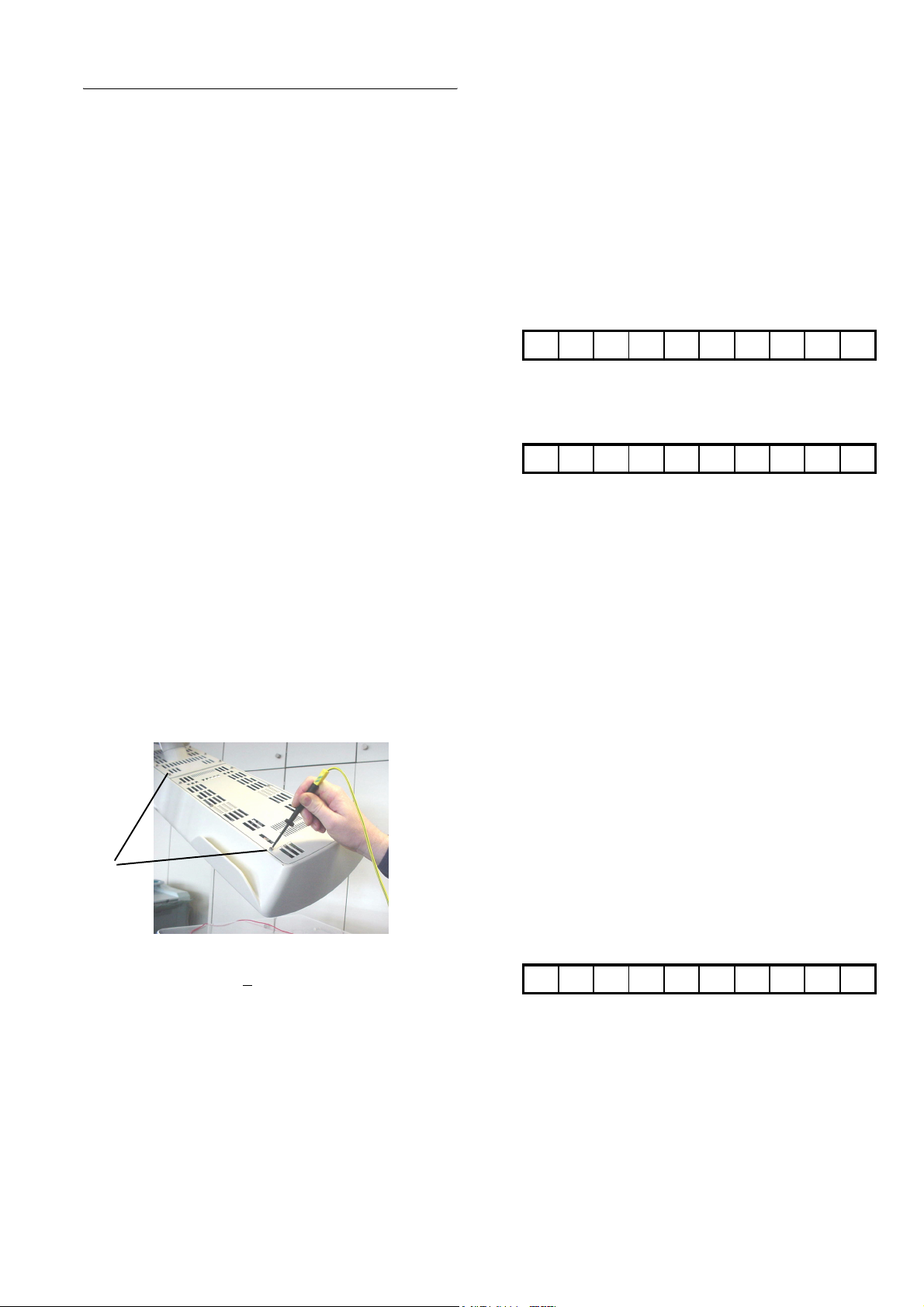
3.1.3 Radiant heater
Use the test probe to measure the
following protective earth conductor
resistances:
ohms.
O
O
3.1.3.1 Screws
Measure at screws (1).
(Note: The screws are located on the top
side of the radiant heater.)
1
The protective earth conductor resistance
should be <
0.2 ohms.
O
5/17
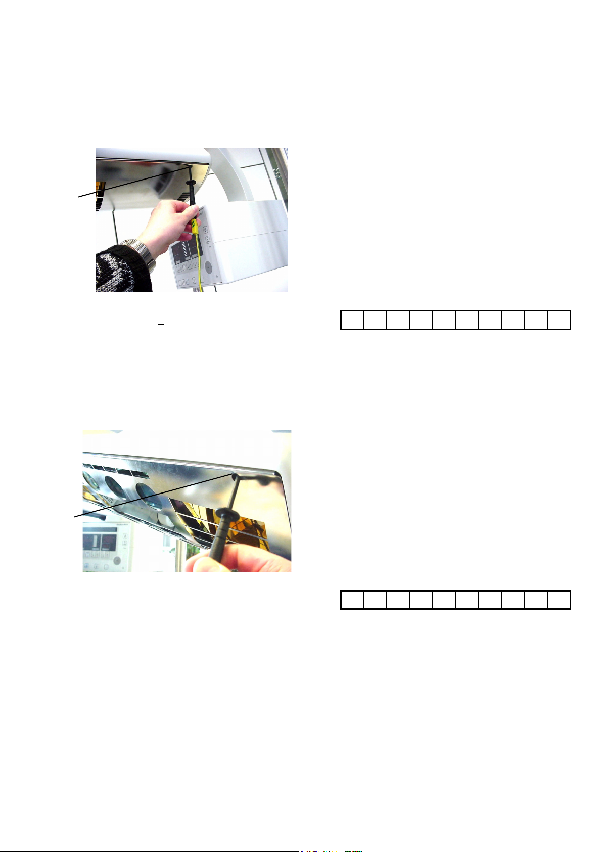
3.1.3.2 Screw of protective screen
Measure at screw (2).
(Note: The radiant heater should be in its
normal position.)
2
The protective earth conductor resistance
should be <
3.1.3.3 Screw of protective screen
0.2 ohms.
O
Measure at screw (3).
(Note: The radiant heater should be in
its swivel end position.)
3
The protective earth conductor resistance
should be <
0.2 ohms.
O
6/17
 Loading...