


 Loading...
Table of Contents
SAFETY PRECAUTION....................................................................................................... |
1 |
INTRODUCTION.................................................................................................................. |
1 |
PACKAGE CONTENTS ....................................................................................................... |
2 |
SYSTEM REQUIREMENTS................................................................................................. |
3 |
Features ........................................................................................................................ |
4 |
INSTALLATION ................................................................................................................... |
5 |
Before You Begin .......................................................................................................... |
5 |
Installation Notes........................................................................................................... |
5 |
Information you will need from your ADSL service provider .......................................... |
7 |
Information you will need about your DSL-2544n ADSL Router.................................... |
8 |
Information you will need about your LAN or computer................................................. |
9 |
Hardware Description and Installation......................................................................... |
10 |
LED Indicators...................................................................................................... |
10 |
Button and interfaces ........................................................................................... |
11 |
Best location for Wireless Operation .................................................................... |
11 |
Connecting the Router ......................................................................................... |
12 |
WEB CONFIGURATION .................................................................................................... |
14 |
Accessing the router.................................................................................................... |
14 |
Configuring IP Address of the Network Card........................................................ |
14 |
SETUP ............................................................................................................................... |
15 |
Wizard.................................................................................................................. |
15 |
Internet setup ....................................................................................................... |
18 |
2.4G Wireless....................................................................................................... |
22 |
5G Wireless.......................................................................................................... |
23 |
Local Network ...................................................................................................... |
24 |
Local IPv6 Network .............................................................................................. |
27 |
Time and Date...................................................................................................... |
28 |
Logout .................................................................................................................. |
28 |
ADVANCED ....................................................................................................................... |
29 |
2.4G Advanced wireless....................................................................................... |
29 |
5G Advanced wireless.......................................................................................... |
33 |
ALG...................................................................................................................... |
33 |
Port forwarding..................................................................................................... |
34 |
DMZ ..................................................................................................................... |
35 |
SAMBA ................................................................................................................ |
36 |
Parental Control ................................................................................................... |
37 |
Filtering Options ................................................................................................... |
39 |
QoS...................................................................................................................... |
41 |
SPI/DOS Protection ............................................................................................. |
43 |
DNS ..................................................................................................................... |
44 |
Dynamic DNS....................................................................................................... |
45 |
Storage Service.................................................................................................... |
46 |
Network Tools....................................................................................................... |
46 |
Routing................................................................................................................. |
50 |
NAT ...................................................................................................................... |
53 |
Logout .................................................................................................................. |
54 |
MAINTENANCE ................................................................................................................ |
55 |
System ................................................................................................................ |
55 |
Firmware Update................................................................................................. |
56 |
Access Controls .................................................................................................. |
56 |
Diagnostics.......................................................................................................... |
58 |
Log Configuration ................................................................................................ |
61 |
Logout ................................................................................................................. |
61 |
TROUBLESHOOTING ...................................................................................................... |
62 |
NETWORKING BASICS............................................................................................. |
64 |
CHECK YOUR IP ADDRESS ..................................................................................... |
64 |
STATICALLY ASSIGNING AN IP ADDRESS .................................................................. |
65 |
TECHNICAL SPECIFICATIONS ....................................................................................... |
66 |

Section 1 – Product Overview
Safety Precaution
Follow the following instructions to prevent the device from risks and damage
•Use the label-marked power.
•Use the power adapter in the package.
•An overburden power outlet or damaged lines and plugs may cause electric shock or fire accident. Check the power cords regularly. If you find any damage, replace it at once.
•Proper space left for heat dissipation is necessary to avoid overheating. The holes on the device are designed for heat dissipation to ensure running normally. Do not cover these heat dissipation holes.
•Do not put this device close to a heat source or high temperature place. Avoid the device direct exposing sunshine.
•Do not put this device close to over damp place. Do not spill any fluid on this device.
•Do not connect this device to PC or electronic product, unless our customer engineer or your broadband provider instructs you to do this, because any wrong connection may cause power or fire risk.
•Do not place this device on an unstable surface or support.
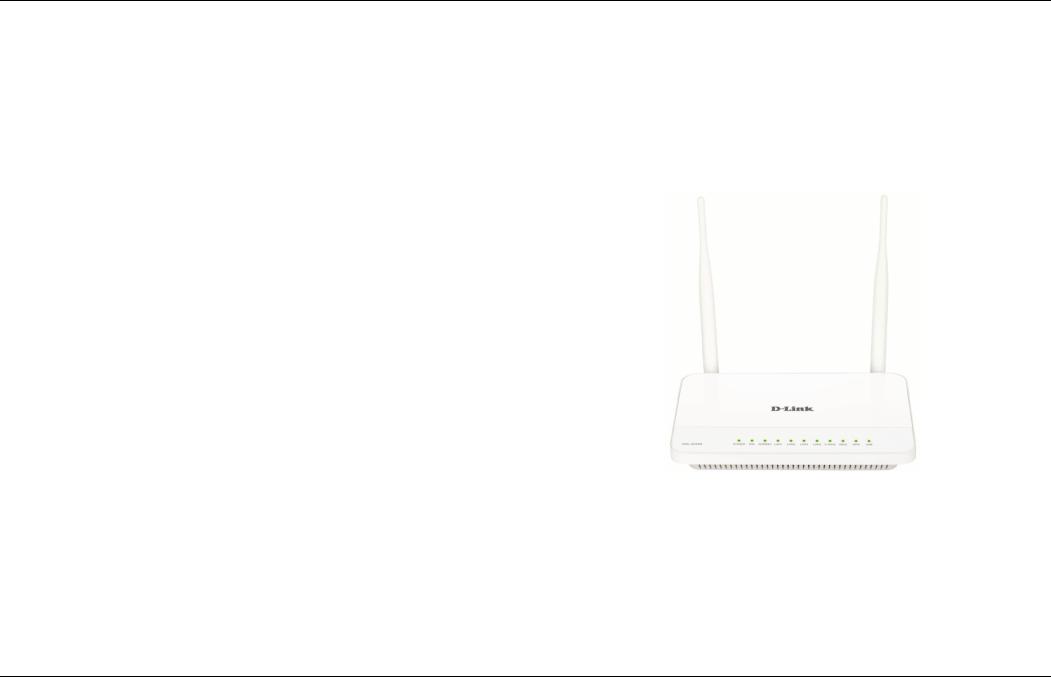
Introduction
The DSL-2544N is a highly integrated ADSL2/2+ Integrated Access Device. It provides DSL uplink, Ethernet LAN and wireless LAN services. The wireless LAN is complied with the IEEE802.11b/g /n standards and supports 2T2R which can work at dual-band 2.4G and 5G. It is usually prefered to provide high access performance applications for the individual users, the SOHO, the small enterprises and so on.
D-Link DSL-2544N User Manual |
1 |
Section 1 – Product Overview
Package Contents
•1 x DSL-2544N Router
•1 x Power adapter
•1 x Splitter
•1 x RJ11 Phone Cable
•1 x RJ45 Ethernet cable
•1 x Installation CD
Note: Using a power supply with a different voltage rating other than the one included with the DSL-2544N may cause damage and void the warranty for this product.
D-Link DSL-2544N User Manual |
2 |

Section 1 – Product Overview
System Requirements
Recommended system requirements are as follows:
1.ADSL Internet service Computer with
•An 10 base T/100BaseT Ethernet card is installed on your PC
•A hub or switch (attached to several PCs through one of Ethernet interfaces on your router)
•Operating system: Windows 8/7/VISTA/XP/2000
•MAC OS
•Internet Explorer V6 or higher, Netscape V4.0 or higher, or Firefox v1.5 or higher
•
D-Link Click’s Connect Utility Computer with:
•Operating system: Windows 8/7/VISTA/XP/2000
•CD-ROM Drive
D-Link DSL-2544N User Manual |
3 |

Section 1 – Product Overview
1
Features
The device supports the following features:
•Various line modes
•External PPPoE dial-up access
•Internal PPPoE/PPPoA dial-up access
•1483Bridged/1483Routed with dynamic ip or static ip
•Dual band wireless network (2.4G and 5G).
•Multiple PVCs (the number of PVCs support is eight)
•DHCP server/relay
•Static route
•Network Address Translation(NAT)
•DMZ
•Virtual Server
•Universal plug and play (UPnP)
•Dynamic Domain Name Server(DDNS)
•One-level password and username
•Network Time Protocol(NTP)
•Firmware upgrading through Web, TFTP, or FTP
•Resetting to the factory defaults through Reset button or Web
•Diagnostic test
•Web interface
•Telnet CLI
•IP/MAC/URL Filter
•Application layer service
•Quality of Service (QoS)
•Port binding
•Auto upgrade
•Net USB
•Digital Living Network Alliance (DLNA)
D-Link DSL-2544N User Manual |
4 |

Section 2 – Installation
Installation
This section will walk you through the installation process. Placement of the Router is very important. Do not place the Router in an enclosed area such as a closet, cabinet or in the attic or garage.
Before You Begin
Please read and make sure you understand all the prerequisites for proper installation of your new Router. Have all the necessary information and equipment on hand before beginning the installation.
Installation Notes
In order to establish a connection to the Internet it will be necessary to provide information to the Router that will be stored in its memory. For some users, only their account information (Username and Password) is required. For others, various parameters that control and define the Internet connection will be required. You can print out the two pages below and use the tables to list this information. This way you have a hard copy of all the information needed to setup the Router. If it is necessary to reconfigure the device, all the necessary information can be easily accessed. Be sure to keep this information safe and private.
Low Pass Filters
Since ADSL and telephone services share the same copper wiring to carry their respective signals, a filtering mechanism may be necessary to avoid mutual interference. A low pass filter device can be installed for each telephone that shares the line with the ADSL line. These filters are easy to install passive devices that connect to the ADSL device and/or telephone using a standard telephone cable. Ask your service provider for more information about the use of low pass filters with your installation.
Operating Systems
The DSL-2544N uses an HTML-based web interface for setup and management. The web configuration manager may be accessed using any operating system capable of running web browser software, including Windows, Mac OS and Linux.
D-Link DSL-2544N User Manual |
5 |

Section 2 – Installation
Web Browser
Any common web browser can be used to configure the Router using the web configuration management software. The program is designed to work best with more recently released browsers such as Opera, Microsoft Internet Explorer® version 6.0, Netscape Navigator® version 6.2.3, or later versions. The web browser must have JavaScript enabled. JavaScript is enabled by default on many browsers. Make sure JavaScript has not been disabled by other software (such as virus protection or web user security packages) that may be running on your computer.
Ethernet Port (NIC Adapter)
Any computer that uses the Router must be able to connect to it through the Ethernet port on the Router. This connection is an Ethernet connection and therefore requires that your computer be equipped with an Ethernet port as well. Most notebook computers are now sold with an Ethernet port already installed. Likewise, most fully assembled desktop computers come with an Ethernet NIC adapter as standard. If your computer does not have an Ethernet port, you must install an Ethernet NIC adapter before you can use the Router. If you need to install an adapter, follow the installation instructions that come with the Ethernet NIC adapter.
Additional Software
It may be necessary to install software on your computer that enables the computer to access the Internet. Additional software must be installed if you are using the device as a simple bridge. For a bridged connection, the information needed to make and maintain the Internet connection is stored on another computer or gateway device, not in the Router itself.
If your ADSL service is delivered through a PPPoE or PPPoA connection, the information needed to establish and maintain the Internet connection can be stored in the Router. In this case, it is not necessary to install software on your computer. It may however be necessary to change some settings in the device, including account information used to identify and verify the connection.
All connections to the Internet require a unique global IP address. For bridged connections, the global IP settings must reside in a TCP/IP enabled device on the LAN side of the bridge, such as a PC, a server, a gateway device, such as a router, or similar firewall hardware. The IP address can be assigned in a number of ways. Your network service provider will give you instructions about any additional connection software or NIC configuration that may be required.
D-Link DSL-2544N User Manual |
6 |

Section 2 – Installation
Information you will need from your ADSL service provider
Username
This is the Username used to log on to your ADSL service provider’s network. Your ADSL service provider uses this to identify your account.
Password
This is the Password used, in conjunction with the Username above, to log on to your ADSL service provider’s network. This is used to verify the identity of your account.
WAN Setting / Connection Type
These settings describe the method your ADSL service provider uses to transport data between the Internet and your computer. Most users will use the default settings. You may need to specify one of the following WAN Setting and Connection Type configurations (Connection Type settings listed in parenthesis):
PPPoE/PPPoA (PPPoE LLC, PPPoA LLC or PPPoA VC-Mux)
Bridge Mode (1483 Bridged IP LLC or 1483 Bridged IP VC Mux)
IPoA/MER (Static IP Address) (Bridged IP LLC, 1483 Bridged IP VC Mux, 1483 Routed IP LLC, 1483 Routed IP VC-Mux or IPoA)
MER (Dynamic IP Address) (1483 Bridged IP LLC or 1483 Bridged IP VC-Mux)
Modulation Type
ADSL uses various standardized modulation techniques to transmit data over the allotted signal frequencies. Some users may need to change the type of modulation used for their service. The default DSL modulation (ADSL2+ Multi-Mode) used for the Router automatically detects all types of ADSL, ADSL2 and ADSL2+ modulation.
Security Protocol
This is the method your ADSL service provider will use to verify your Username and Password when you log on to their network. Your Router supports the PAP and CHAP protocols.
VPI
Most users will not be required to change this setting. The Virtual Path Identifier (VPI) is used in conjunction with the Virtual Channel Identifier (VCI) to identify the data path between your ADSL service provider’s network and your computer. If you are setting up the Router for multiple virtual connections, you will need to configure the VPI and VCI as instructed by your ADSL service provider for the additional connections. This setting can be changed in the WAN Settings window of the web management interface.
VCI
Most users will not be required to change this setting. The Virtual Channel Identifier (VCI) is used in conjunction with the VPI to identify the data path between your ADSL service provider’s network and your computer. If you are setting up the Router for multiple virtual connections, you will need to configure the VPI and VCI as instructed by your ADSL service provider for the additional connections. This setting can be changed in the WAN Setup window of the web management interface.
D-Link DSL-2544N User Manual |
7 |

Section 2 – Installation
Information you will need about your DSL-2544N ADSL Router
Username
This is the Username needed to access the Router’s management interface. When you attempt to connect to the device through a web browser you will be prompted to enter this Username. The default Username for the Router is “admin.” The user cannot change this.
Password
This is the Password you will be prompted to enter when you access the Router’s management interface. The default Password is “admin.” The user may change this.
LAN IP addresses for the DSL-2544N
This is the IP address you will enter into the Address field of your web browser to access the Router’s configuration graphical user interface (GUI) using a web browser. The default IP address is 192.168.1.1. This may be changed to suit any IP address scheme the user desires. This address will be the base IP address used for DHCP service on the LAN when DHCP is enabled.
LAN Subnet Mask for the DSL-2544N
This is the subnet mask used by the DSL-2544N and will be used throughout your LAN. The default subnet mask is 255.255.255.0. This can be changed later.
D-Link DSL-2544N User Manual |
8 |
Section 2 – Installation
Information you will need about your LAN or computer
Ethernet NIC
If your computer has an Ethernet NIC, you can connect the DSL-2544N to the Ethernet port using an Ethernet cable. You can also use the Ethernet ports on the DSL-2544N to connect to other computers or Ethernet devices.
DHCP Client status
Your DSL-2544N ADSL Router is configured, by default, to be a DHCP server. This means that it can assign an IP address, subnet mask and a default gateway address to computers on your LAN. The default range of IP addresses the DSL-2544N will assign are from 192.168.1.2 to 192.168.1.254. Your computer (or computers) needs to be configured to obtain an IP address automatically (that is, they need to be configured as DHCP clients.)
It is recommended that you collect and record this information here, or in some other secure place, in case you have to re-configure your ADSL connection in the future.
Once you have the above information, you are ready to setup and configure your DSL-2544N ADSL Router.
D-Link DSL-2544N User Manual |
9 |
Section 2 – Installation
Hardware Description and Installation
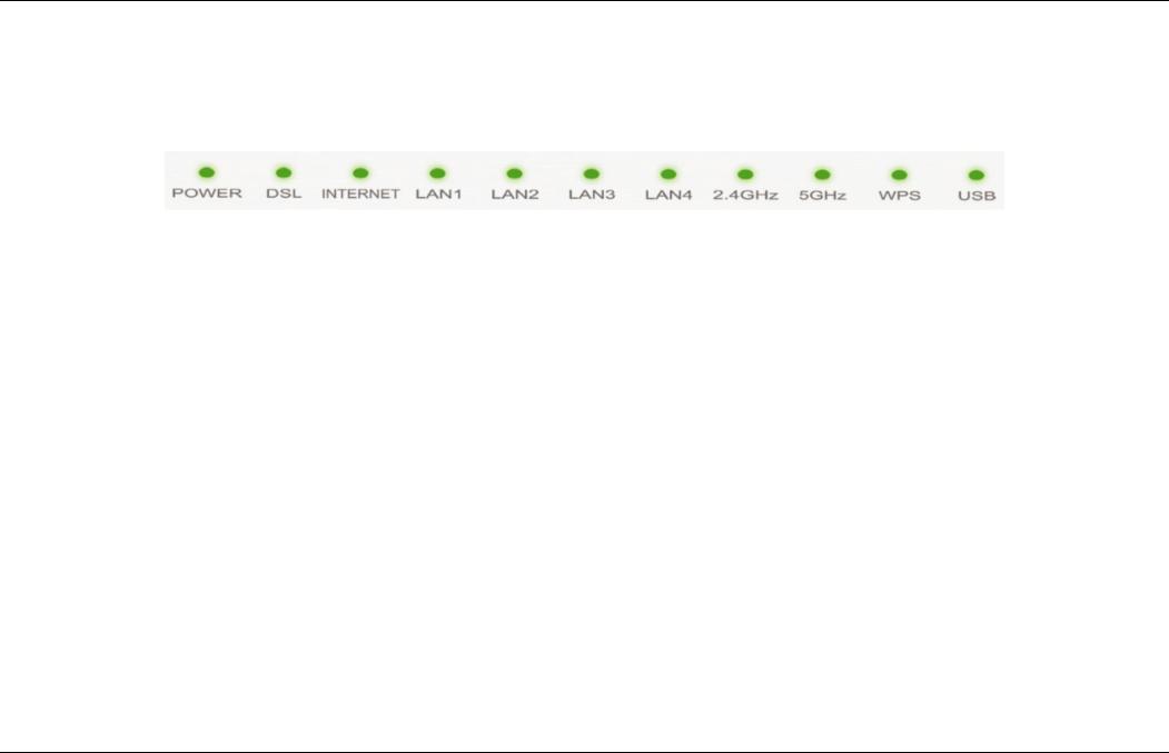
LED Indicators
Note: The figures in this document are for reference only.
|
|
|
|
Figure 1 Front panel |
The following table describes the LEDs of the device. |
||||
|
LED |
Color |
Status |
Description |
|
|
Green |
On |
The initialization of the system is complete. |
|
Power |
Red |
On |
The device is powered on. |
|
|
Blinking |
The firmware is upgrading. |
|
|
|
|
||
|
|
|
Off |
No signal is being detected. |
|
DSL |
Green |
Blinking |
The device is handshaking with the physical layer of the office end. |
|
|
|
On |
A connection is set up with the physical layer of the office end. |
|
|
Green |
Off |
The device is under the Bridge mode or powered off. |
|
Internet |
On |
A successful connection has been made. |
|
|
|
|||
|
Red |
On |
The authentication of the PPP dial-up has failed or MER has failed to obtain the correct IP |
|
|
|
|||
|
|
address. |
||
|
|
|
|
|
|
|
|
Off |
The Ethernet interface is not properly connected. |
|
LAN 1/2/3/4 |
Green |
Blinking |
The Ethernet interface is properly connected and data is being transmitted. |
|
|
|
On |
The Ethernet interface is properly connected, but no data is being transmitted. |
|
|
|
Blinking |
The WLAN function is enabled and data is being transmitted on the WLAN. |
|
2.4GHz/5GHz |
Green |
On |
The WLAN function is enabled, but no data is being transmitted on the WLAN. |
|
|
|
Off |
The WLAN function is disabled. |
|
|
|
On |
The USB connection is set up or USB flash disk is enabled. |
|
USB |
Green |
Blinking |
A connection is set up and data is being transmitted. |
|
|
|
Off |
No signal is detected. |
|
WPS |
Green |
Solid light |
Connection is successfully established between the router and the client, the LED would light |
|
steady for 5 seconds. |
|||
|
|
|
|
|
D-Link DSL-2544N User Manual |
10 |
Section 2 – Installation
LED |
Color |
Status |
Description |
|
|
Blinking |
WPS is successfully triggered. |
|
|
Off |
Device is ready for new WPS setup. |
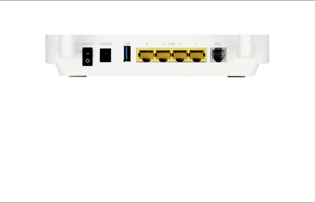
Button and Interfaces
|
|
Figure 2 Rear panel |
The following table describes the interfaces of the device. |
||
|
Interface/Button |
Description |
|
ON/OFF |
Power switch, which is used to power on or power off the device. |
|
POWER |
Interface for connecting the power adapter. |
|
USB |
USB port for connecting a USB storage device. |
|
LAN4/3/2/1 |
RJ-45 interface for connecting the device to the Ethernet interface of PC or other Ethernet devices through |
|
the Ethernet cable. |
|
|
|
|
|
DSL |
RJ-11 interface for connecting the device to the telephone jack on the wall or the MODEM interface of the |
|
splitter through a telephone line. |
|
|
|
|
|
|
Press and hold the button for 5 seconds to start 2.4GHz WPS negotiation. Press and hold for 5 to 10 |
|
WPS (on the side panel) |
seconds to start 5GHz WPS negotiation. |
|
|
Press and hold the button for 15 seconds to restore the factory defaults. |
|
|
|
Best Location for Wireless Operation
Many environmental factors may affect the effective wireless function of the DSL Router. If this is the first time that you set up a wireless network device, read the following information:
The access point can be placed on a shelf or desktop, ideally you should be able to see the LED indicators in the front, as you may need to view them
D-Link DSL-2544N User Manual |
11 |
Section 2 – Installation
for troubleshooting.
Designed to go up to 100 meters indoors and up to 300 meters outdoors, wireless LAN lets you access your network from anywhere you want. However, the numbers of walls, ceilings, or other objects that the wireless signals must pass through limit signal range. Typical ranges vary depending on types of materials and background RF noise in your home or business.
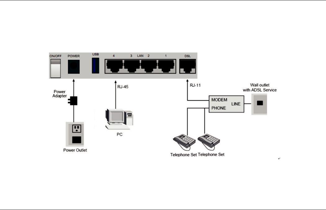
Connecting the Router
The following figure shows the connection of the Router, PC, and telephones.
Step 1 Connect the DSL port of the router and the Modem port of the splitter through a telephone cable; connect the phone to the phone port of the splitter through a telephone cable; and connect the Line port of the splitter to the uplink telephone jack on the wall.
The spliter has three ports:
LINE: Connect to a wall phone jack (RJ-11 jack)
Modem: Connect to the Line interface of the router
D-Link DSL-2544N User Manual |
12 |

Section 2 – Installation
PHONE: Connect to a telephone set
Step 2 Connect the LAN port of the router to the network interface card (NIC) of the PC through an Ethernet cable (MDI/MDIX). Step 3 Plug the power adapter to the wall outlet and then connect the other end of it to the Power port of the route
D-Link DSL-2544N User Manual |
13 |

Section 3 – Web Configuration
Web Configuration
This chapter describes how to use Web-based management of the DSL router, which allows you to configure and control all of DSL router features and system parameters in a user-friendly GUI.
Accessing the Router
Configuring IP Address of the Network Card
Configure TCP/IP properties of your network card to Obtain an IP address automatically from modem, or set the IP address of the computer with the same network mask of the modem.
For example, if the IP address of Router is 192.168.1.1/255.255.255.0, you can set the IP address of the computer to 192.168.1.x/255.255.255.0. The range for x is from 2 to 254.
The following description is a detail “How-To” user guide and is prepared for first time users.
Step 1 Open the Internet Explorer (IE) browser, and then go to http://192.168.1.1.
Step 2 The Login page is shown as the figure appears on the right. Select admin from the drop-down list of username and enter the password.
The password is admin.
D-Link DSL-2544N User Manual |
14 |

Section 3 – Web Configuration
Step 3 If you log in as admin successfully, the page is shown as the figure appears on the right. You can query, configure, and modify all configurations, and diagnose the system.
SETUP
Wizard
Wizard enables fast and accurate configuration of Internet connection and other important parameters. The following sections describe these various configuration parameters.
When subscribing to a broadband service, you should be aware of the method, by which you are connected to the Internet. The connection type of your physical WAN device can be Ethernet, DSL, or both. Technical information about the properties of your Internet connection is provided by your Internet service provider (ISP). For example, your ISP should inform you whether you are connected to the Internet using a static or dynamic IP address, or the protocol, such as PPPoA or PPPoE, that you use to communicate over the Internet.
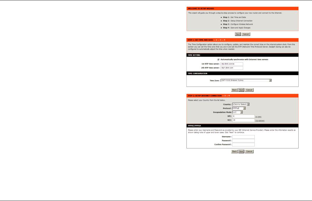
Step 1 Choose SETUP > Wizard. The page is shown as the figure appears on the right.
D-Link DSL-2544N User Manual |
15 |
Section 3 – Web Configuration
Step 2 Click Setup Wizard. The page is shown as the figure appears on the right.
Step 3 There are four steps to configure the device. Click Next to continue. Step 4 Set the time and date, and click Next.
Step 5 Configure the Internet connection.
-PPPoE/PPPoA
Select the country and ISP. Set the VPI and VCI. If you fail to find the country and ISP from the drop-down lists, select Others, and then click
Next. If the Protocol is set to be PPPoE or PPPoA and Connection Type is LLC, the page is shown as the figure appears on the right.
In this page, enter the user name and password provided by your ISP.
D-Link DSL-2544N User Manual |
16 |
Section 3 – Web Configuration
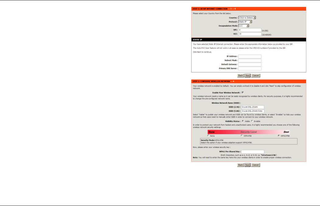
-Static IP
If the internet service you subscribed is Static IP, the Protocol is set to be Static IP, the page shown as the figure appears on the right.
In this page, enter the IP Address, Subnet Mask, Default Gateway and
Primary DNS Server provided by your ISP.
If the Protocol is set to be Dynamic IP and Bridge, the content of the page will be slightly different.
After settings, click Next to go to the next page.
Step 6 Configure the wireless network. Enter the information and click Next. The following table describes the fields in this page.
Field |
Description |
|
Enable |
Your |
To enable or disable wireless network |
Wireless |
|
connection. |
Network |
|
|
Wireless |
|
Set a name for your wireless network. |
Network |
Name |
|
(SSID) |
|
|
|
|
Visible: Your SSID can be found by wireless |
Visibility status |
clients. |
|
Invisible: Your SSID is hided. Wireless clients |
||
|
|
need to manually enter your SSID and connect. |
|
|
|
|
|
You can choose a security mode to protect your |
Security Mode |
wireless network. It is recommended selecting |
|
|
|
WPA2-PSK. |
WPA2 |
|
Enter a password. The length of the password is |
Pre-Shared Key |
between 8-63 characters. |
|
D-Link DSL-2544N User Manual |
17 |
Section 3 – Web Configuration
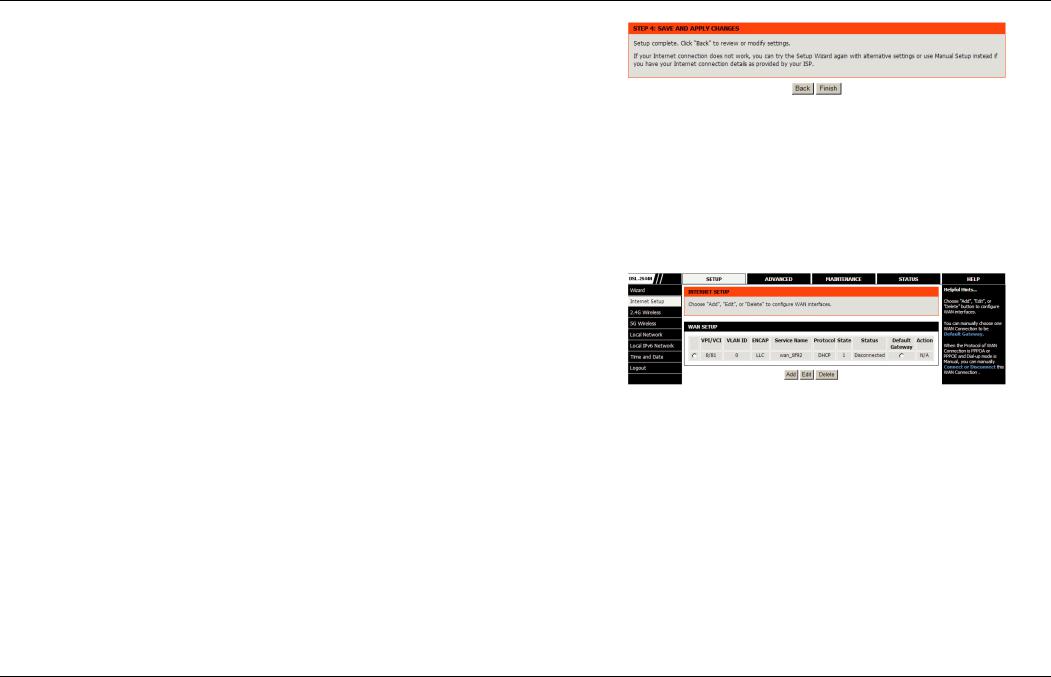
Step 7 Click Apply to apply the current settings and finished the setup of the
DSL-2544N router. Click Back to review or modify settings.
Note: In each step of the Wizard page, you can click Back to review or modify the previous settings. Click Cancel to exit the wizard page.
Internet Setup
Choose SETUP > Internet Setup. The page is shown as the figure appears on the right. In this page, you can configure the WAN interface of the device.
D-Link DSL-2544N User Manual |
18 |
Section 3 – Web Configuration
Click Add in the page of INTERNET SETUP. The page is shown in the figure appears on the right.
The following table describes the parameters in this page.
Field |
Description |
|
VPI |
The virtual path between two points in an |
ATM |
network and its valid value is from 0 to 255. |
|
|
|
|
|
|
The virtual channel between two points in an ATM |
|
VCI |
network, ranging from 32 to 65535 (0 to 31 is |
|
|
reserved for local management of ATM traffic). |
|
Service |
You can select from the drop-down list. |
|
Category |
|
|
QoS Scheduler |
You can choose Strict Priority or Weighted |
Fair |
Queuing. |
|
|
|
|
|
Protocol |
You can select from the drop-down list. |
|
Encapsulation |
Select the method of encapsulation provided by your |
|
Mode |
ISP. You can select from the drop-down list. |
|
After setting, click Apply to save the settings.
D-Link DSL-2544N User Manual |
19 |
Loading...