

Page 1

Version 1.01 | 10/07/2013
User Manual
mydlink Camera Video Recorder
DNR-202L
Page 2

Preface
D-Link reserves the right to revise this publication and to make changes in the content hereof without obligation to notify any person or
organization of such revisions or changes. Information in this document may become obsolete as our services and websites develop and
change.
Manual Revisions
Revision Date Description
1.0 August 7, 2013 DNR-202L Revision A1 with rmware version 1.00
1.01 October 7, 2013 Updated with minor changes
Trademarks
D-Link and the D-Link logo are trademarks or registered trademarks of D-Link Corporation or its subsidiaries in the United States or other
countries. All other company or product names mentioned herein are trademarks or registered trademarks of their respective companies.
Copyright © 2013 D-Link Corporation.
All rights reserved. This publication may not be reproduced, in whole or in part, without prior expressed written permission from D-Link Corporation.
2D-Link DNR-202L User Manual
Page 3

Table of Contents
Product Overview ......................................................................... 4
Package Contents ................................................................. 4
Introduction ............................................................................5
System Requirements ......................................................... 5
Features ....................................................................................6
Hardware Overview ............................................................. 7
Assembly and Installation ......................................................... 8
Attaching External Drives .................................................. 8
Software Installation ........................................................... 9
Adding Cameras using the Setup Software ..............15
HDD Viewer Software Installation ................................19
HDD Viewer Software Interface .....................................20
Open Recording ..............................................................21
mydlink Portal ..............................................................................22
NVR Status Icons .............................................................23
Settings ..................................................................................24
Live Video ..............................................................................25
Using the Conguration Interface ................................36
Live Video ..............................................................................37
Playback .................................................................................39
Searching Recordings ...................................................41
Save Recording to AVI ...................................................43
Save Snapshot ..................................................................44
Print Snapshot .................................................................44
Setup .......................................................................................45
Network Setup .................................................................48
Add Camera ......................................................................49
Audio and Video ..............................................................50
Event Setup .......................................................................51
Time and Date Setup .....................................................52
Maintenance .........................................................................53
User Management ..........................................................53
System ................................................................................54
Firmware Update ............................................................55
Playback .................................................................................26
Open Recording ..............................................................27
Status ......................................................................................28
NVR Info..................................................................................29
mydlink View - NVR App...........................................................30
First Use - Select Your Device ..........................................31
Live View ................................................................................31
Video Playback .....................................................................34
Video Playback Control .....................................................35
Conguration ...............................................................................36
Hard Drive Conguration .............................................56
Status ......................................................................................57
Camera Status ..................................................................57
System Info ........................................................................58
Logs .....................................................................................59
Support ..............................................................................60
LED and Buzzer Overview ................................................61
Technical Specications ...................................................62
3D-Link DNR-202L User Manual
Page 4

Section 1: Product Overview
DNR-202L mydlink Camera Video Recorder
Power adapter
CAT5 Ethernet cable
Product Overview
Package Contents
Quick Installation Guide
CD-ROM with User Manual and software
If any of the above items are missing, please contact your reseller.
Note: Using a power supply with a dierent voltage than the one included with your product will cause damage and void the warranty
for this product.
4D-Link DNR-202L User Manual
Page 5

Section 1: Product Overview
Introduction
Congratulations on your purchase of the DNR-202L mydlink Camera Video Recorder.
The DNR-202L is a wired Network Video Recorder (NVR) which supports up to four network cameras with M-JPEG, MPEG4, or
H.264 recording with up to two attached USB hard disks. Thanks to the powerful embedded system, the NVR can record video
from network cameras located in local or remote sites to dedicated disk storage without needing a PC.
Powered by mydlink technology, the DNR-202L can be easily setup for Internet access. It supports real-time monitoring and
playback from anywhere via an Internet browser. Users can keep recording while viewing a live feed or while searching playback
at the same time. Complete video management, display, and playback ability makes the DNR-202L a convenient and stable
video recording solution.
System Requirements
• Computer with Microsoft Windows 8®, Windows 7, Vista®, XP, or Mac OS 10.5 or above
• PC with Pentium 4 – 2.4 GHz or above, at least 512 MB RAM
• Internet Explorer 8 and above, Firefox 3.5 or above, Safari 4 or above, Chrome 2 or above
• Existing 10/100 Ethernet-based network
• Broadband Internet connection
5D-Link DNR-202L User Manual
Page 6

Section 1: Product Overview
Comprehensive IP Surveillance Solution
• Total Solution: The D-Link DNR- 202L is a Network Video Recorder (NVR) capable of 24/7 recording without requiring a PC. The DNR-202L
can manage multiple network cameras, providing direct access to view live video and play recorded data through the Internet from
anywhere, anytime. The device itself is light weight and compact in size.
• Easy to Use: A user-friendly GUI simplies network and camera setup, allowing users to easily access multiple cameras for viewing,
recording, playback, and conguration.
• Centralized Interface for Conguration: The DNR-202L provides a exible and economic alternative to manage and congure multiple
network cameras on a centralized web interface.
• Megapixel Resolution Support: The major advantage of digital over analog video is its higher resolution support. The DNR-202L supports
high resolution megapixel recording for vivid video with high clarity.
• Empowered by mydlink technology: The DNR-202L can be easily setup for Internet access. It supports real-time monitoring and playback
from anywhere via an Internet browser.
Powerful Event Management
1. Camera Status: The camera status page will show connection, recording, frame rate, and bit rate information of each camera. Meanwhile,
the estimated available recording time is also displayed for quick reference.
2. Flexible Event Management: Event setup is another key feature of the DNR-202L. The NVR can monitor all of the camera triggers for
motion detection. One of the most powerful functions is the notication application. The NVR centrally controls the e-mail notications
and recording from all connected cameras.
Instant Live View
1. Full Screen: Enlarge the display to full screen of live view and recorded video.
2. Camera Name and Status on OSD: Camera name and recording status are displayed via OSD to aid in identication.
3. PTZ/Audio Support: Users can control pan/tilt/zoom (PTZ) functions from within the interface using the provided interface buttons.
4. Preset Point: Presets from within the interface can be set to instantly restore a previously saved viewpoint.
5. Digital Zoom: Videos can be enlarged by using digital zoom.
Intelligent Playback
1. AVI Output: During playback, if you uncover video that needs to be exported, you can easily export video in the convenient AVI format.
2. Playback Speed Control: Playback speed control allows for up to 32x speed fast forward or fast backward play. The step playback option
displays one frame at a time.
3. Image Enhancement: Users can enhance the recorded video with controls such as brightness, contrast, and sharpness.
4. Print Picture: If a printer is connected to the user’s PC, the NVR can also print the selected still image.
Features
6D-Link DNR-202L User Manual
Page 7

Section 1: Product Overview
Hardware Overview
1
Right View
3
4
2
1 Power Receptor
2 RJ45 Connector Connect one end of the provided network cable.
3 USB Port for HDD 1 Attach an external USB Hard Disk (HDD) to this port to save recorded streams
4 HDD 1 Release Button
Connect the provided power adaptor
Press this button to release the HDD attached to the USB Port for HDD 1
Rear View
6
5
7
8
5 USB Port for HDD 2 Attach an external USB HDD to this port to save recorded streams
6 HDD 2 Release Button
7 Auto Scan Key Press this button to automatically scan for cameras on the network
8 Reset Button
Press this button to release the HDD attached to the USB Port for HDD 2
Press and hold the recessed button for 10 seconds to reset the device
7D-Link DNR-202L User Manual
Page 8

Section 2: Assembly and Installation
Assembly and Installation
Attaching External Drives
Step 1
Place the NVR on a non-slip at surface.
Step 2
Attach an external USB HDD to the USB HDD1 port.
The NVR will mount the HDD and beep once.
Note: When you want to remove an HDD, press and hold the release button for at least three
seconds. The NVR will release the HDD and emit a long beep. You can now unplug the USB cable.
2
Step 3
Attach one end of the provided RJ45 network cable to the NVR. Attach the other end to your
network. The DNR-202L will test for an Internet connection. Once an Internet connection is
established, the blue LED will blink.
Note: If you do not connect an Ethernet cable, the DNR-202L will beep.
Step 4
Attach the provided power adaptor.
4
3
8D-Link DNR-202L User Manual
Page 9

Section 2: Assembly and Installation
Software Installation
Step 1
Insert the Installation CD-ROM into your computer’s optical drive to start the
autorun program.
Windows Users:
The CD-ROM will open the Setup Wizard. The Setup Wizard will guide you through
the installation process through to conguring the NVR.
Note:
If the autorun program does not automatically start on your computer, go to
Windows and click Start > Run. In the Run command box type D:\autorun.exe,
where D: represents your CD-ROM drive.
OS X Users:
Insert the DNR-202L Driver CD in the CD -ROM drive. After you have inserted the
CD into your computer, go to the CD drive directory, and double-click the Mac
Utility folder to enter.
Step 2
Accept the End User Licence Agreement and follow the on-screen prompts.
9D-Link DNR-202L User Manual
Page 10

Section 2: Assembly and Installation
Step 3
Select your NVR from the list, then click Next. If you have multiple NVRs, you can
identify them by the MAC ID printed on the label on the bottom of the device.
Step 4
By default the Admin ID is "admin" and the password is blank.
Create and conrm a password for your device.
Click Next to continue.
10D-Link DNR-202L User Manual
Page 11

Section 2: Assembly and Installation
Step 5
The wizard will scan for attached storage and ask if you wish to format the devices
found.
Note: Select Skip if you are unsure of which settings to choose.
Click Next to continue.
Step 6
The wizard will attempt to nd your Internet connection. Select Static IP if your
Internet Service Provider has provided you with connection settings, or if you wish
to set a static address within your home network. Enter the correct conguration
information and click Next to continue.
Note: Select DHCP if you are unsure of which settings to choose.
Click Next to continue.
11D-Link DNR-202L User Manual
Page 12

Section 2: Assembly and Installation
Step 7
The wizard will guide you through the process of connecting your NVR to a mydlink
account. If you already have a mydlink account, enter the correct conguration
information and click Next to continue, otherwise select No, I need to sign up for
a new account or I don't want to sign up right now and follow the instructions.
Click Next to continue.
12D-Link DNR-202L User Manual
Page 13

Section 2: Assembly and Installation
Step 8
The wizard will scan for all available cameras attached to your network. Registered
mydlink cameras will be veried automatically.
After the wizard has completed the scan for all available cameras attached to your
network click on the red icons to conrm/create the password for each camera.
Click Next to continue.
Note: It is strongly advised to setup passwords for all of your cameras.
13D-Link DNR-202L User Manual
Page 14

Section 2: Assembly and Installation
You can preview the discovered cameras by clicking on the green camera icon,
or click Next to continue.
Step 9
Setup is complete. Make a note of the details presented and click on Go to NVR to
log in to the NVR for further conguration (see "Using the Conguration Interface"
on page 36) or click Finish.
14D-Link DNR-202L User Manual
Page 15

Section 2: Assembly and Installation
Adding Cameras using the Setup Software
Step 1
Insert the Installation CD-ROM into your computer’s optical drive to start the
autorun program.
The CD-ROM will open the Setup Wizard. The Setup Wizard will guide you through
the installation process of adding a camera to the NVR.
At the welcome page, click on the Skip button.
Note:
If the autorun program does not automatically start on your computer, go to
Windows and click Start > Run. In the Run command box type D:\autorun.exe,
where D: represents your CD-ROM drive.
Step 2
Follow the on screen prompts to ensure the device is plugged in and powered on.
15D-Link DNR-202L User Manual
Page 16
Section 2: Assembly and Installation
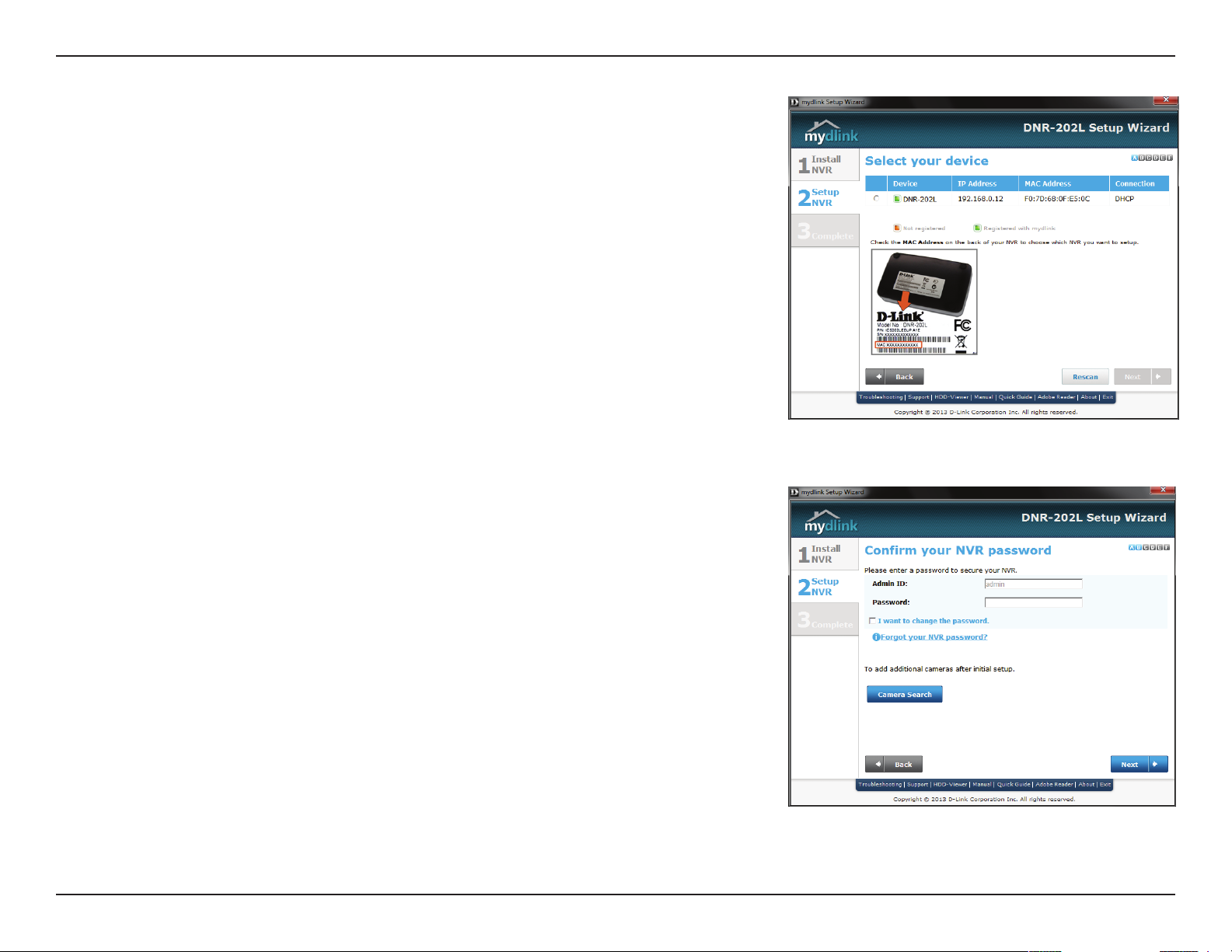
Step 3
Select your NVR from the list, then click Next. If you have multiple NVRs, you can
identify them by the MAC ID printed on the label on the bottom of the device.
Step 4
Conrm the password for your device.
Click Camera Search to continue.
16D-Link DNR-202L User Manual
Page 17

Section 2: Assembly and Installation
Step 5
The wizard will scan for all available cameras attached to your network. Registered
mydlink cameras will be veried automatically.
After the wizard has completed the scan for all available cameras attached to your
network, click on the red icons to conrm/create the password for each camera.
Click Next to continue.
Note: It is strongly advised to setup passwords for all of your cameras.
17D-Link DNR-202L User Manual
Page 18
Section 2: Assembly and Installation
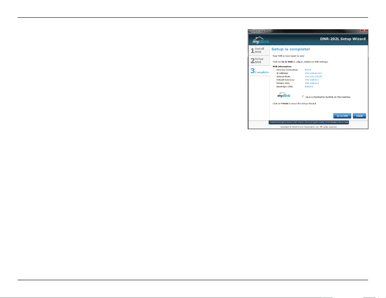
Step 6
Make a note of the details presented and click on Go to NVR to log in to the NVR
for further conguration (see "Using the Conguration Interface" on page 36) or
click Finish.
18D-Link DNR-202L User Manual
Page 19

Section 2: Assembly and Installation
HDD Viewer Software Installation
Your DNR-202L comes with a convenient application to assist you in managing your recorded video. This section will guide
you thorugh the simple setup procedure, and the interface of the application.
Step 1
Attach the hard disk containing the DNR-202L recordings you wish to view.
Step 2
Insert the DNR-202L Driver CD in the CD-ROM drive. Navigate to the D:\HddViewer
folder (where D: represents the drive letter of your CD-ROM drive) and double
click on the setup program to begin the installation.
Step 3
Follow the on-screen prompts and click Finish to complete the installation.
19D-Link DNR-202L User Manual
Page 20

Section 2: Assembly and Installation
HDD Viewer Software Interface
The HDD-Viewer application enables you to view, search and, backup your recorded videos from a simple interface. The interface controls are
described below. For advanced users refer to "Playback" on page 39 for more details.
Open Recording
Search Menu
Display Single feed Use this button to switch to a single camera feed in
Display 2 x 2 feed
Actual Size Use this button to display the recording in it's native
Full Screen Use this button to switch to a full screen view of the
On Screen Display
Settings
Save as AVI Use this button to export the video as an AVI le.
Print Image Use option this to print a still image.
Save as Image Use this option to save a still image.
Image
Enhancement
Backup Data Use this option to make a backup your video
Volume Use the slider to adjust the playback volume.
Use this button to show the Open Recording menu.
See "Open Recording" on page 21 for more.
the live video display area.
Use this button to switch to a 2 x 2 camera feed in
the live video display area.
resolution.
live video feed.
Use this button to congure the various settings for
the on screen display.
Use this option to apply image enhancements.
recordings.
Close Application Use this button to close the application.
Minimize
Application
Use this button to minimize the application.
20D-Link DNR-202L User Manual
Page 21

Section 2: Assembly and Installation
Open Recording
Click the Open Recording button to access the Date-Time Panel and select the video recordings which you would like to review.
1
3
2
4
5
8
6
9
7
1 Select Folder Use this button to navigate to your video recordings folder.
2 Date Selection Area
3 Time Range Selection Select a beginning and end time for the recording you wish to view.
4 Video Preview When Enable Preview is checked, this area will display a preview.
5 Timeline This timeline will adjust according to the level of zoom selected.
6 Available Streams This area lists the recording devices available.
7 Zoom Slider Use the zoom slider control to zoom in and out of the timeline.
8 Available Recordings
9 Selected Period Click within the timeline to select a recording period.
Select the year, month and day of the recording you wish to view. Dates
with recordings available for playback are highlighted blue.
Recordings are graphed below the timeline. Blue bars indicate an event
was recorded. Red bars indicate the camera is set to always record.
21D-Link DNR-202L User Manual
Page 22

Section 3 - mydlink Portal
mydlink Portal
After registering your NVR with a mydlink account in the NVR Setup Wizard, you
will be able to remotely access your NVR from the www.mydlink.com website.
After you log in to your mydlink account, you be taken to the My Devices page.
To connect to your NVR click on the Connect button and provide your password
to complete the login process. After you have connected to the NVR, you will be
taken to the Live Video page. (Refer to "Live Video" on page 25)
22D-Link DNR-202L User Manual
Page 23

Section 3 - mydlink Portal
NVR Status Icons
Here, you can see the online status of each of your NVRs. Your online status may be one of the following:
A green checkmark indicates that your NVR is online and ready to use.
A yellow exclamation point indicates that your NVR is online, but the NVR
password has changed. You will need to enter your new NVR password to
access your NVR again.
A red cross indicates that your NVR is oine and currently cannot be
accessed remotely.
If your NVR is oine, try the following:
• Check to make sure that the Internet connection to your NVR is working properly.
• Try restarting your Internet router.
• Check your NVR’s cable connections and make sure they are secure.
• Check to make sure that the LED on your NVR is lit solid blue.
If you still cannot access your NVR, reset your NVR and run the NVR Setup Wizard again from the CD-ROM included in your
package.
23D-Link DNR-202L User Manual
Page 24

Section 3 - mydlink Portal
Settings
On the Settings tab you can see a general summary of your NVR.
If you wish to remove your NVR from your mydlink account click on the Delete NVR button and provide your password to
complete the action.
24D-Link DNR-202L User Manual
Page 25

Section 3 - mydlink Portal
Live Video
After you have connected to your NVR, the Live Video tab will be selected by
default and will display the Live Video feed. You can choose a dierent camera
from the drop down list, or you can choose to view all the available channels.
A notice is displayed below the controls if any events have been recorded, or if
the NVR is currently recording.
The available controls are detailed below.
Control Pad This control pad can be used to pan, tilt, and zoom
(PTZ) a dome camera, or electronically pan, tilt, and
zoom (PTZ) within the camera's predened view area, if
one has been dened.
Zoom Control Use the + and - buttons to zoom in or out.
Actual Size Use this control to view video in it's native resolution.
Record Use this control to toggle recording.
Save to Image Use this option to save a snapshot image.
Glance Use this option to toggle the glance mode.
25D-Link DNR-202L User Manual
Page 26

Section 3 - mydlink Portal
Playback
The Playback tab enables the user to review pre-recorded video. The available
playback controls are detailed below.
Playback Seeker Use the playback seeker to quickly jump to a specic
point in the recording.
Volume Control Adjust the slider to increase or decrease the audio
volume.
Open Recording Click on this control to open the saved recordings
search dialog. See "Open Recording" on page 27.
Pause Playback Use this control to pause the current playback.
Stop Playback Use this control to stop the current playback.
Step Back/Forward Use these controls to pause playback and either step
back one frame or advance forward by one frame.
Speed Down/Up Use these controls to slow down or speed up the
playback.
Zoom Control Use the + and - buttons to zoom in or out.
Actual Size Use this control to view video in it's native resolution.
Save to Image Use this option to save a snapshot image.
26D-Link DNR-202L User Manual
Page 27

Section 3 - mydlink Portal
Open Recording
Click the Open Recording button to access the Date-Time Panel and select the video recordings which you would like to review.
1
2
3
4
7
5
6
1 Date Selection Area
2 Time Range Selection Select a beginning and end time for the recording you wish to view.
3 Video Preview When Enable Preview is checked, this area will display a preview.
4 Timeline
5 Available Streams This area lists the recording devices available.
6 Zoom Slider
7 Available Recordings
8 Selected Period
Select the year, month and day of the recording you wish to view. Dates
with recordings available for playback are highlighted blue.
This timeline will adjust according to the level of zoom selected.
Use the zoom slider control to zoom in and out of the timeline.
Recordings are graphed below the timeline. Blue bars indicate an event
was recorded. Red bars indicate the camera is set to always record.
Click within the timeline to select a recording period.
8
27D-Link DNR-202L User Manual
Page 28

Section 3 - mydlink Portal
Status
The Status tab describes both USB storage and cameras connected to the NVR.
Name: This shows the name given to the USB storage device attached to the USB 1 or USB 2
port.
Total Hard Drive Capacity: This shows the total amount of storage space available on the
USB storage device attached to the USB 1 or USB 2 Port.
Used Space: This shows the used storage space of the USB storage device attached to the
USB 1or USB 2 Port.
Unused Space: This shows the amount of space available for recording on the USB storage
device attached to the USB 1 or USB 2 Port.
Status: This shows if the USB storage device attached to the USB 1or USB 2 port is currently
being recorded to.
Advanced Settings: Clicking on the Advanced Settings button allows you to access your NVR’s
conguration interface. To open your NVR’s conguration interface, select the NVR web page
and enter the password.
28D-Link DNR-202L User Manual
Page 29

Section 3 - mydlink Portal
NVR Info
The NVR Info tab shows you various information about your NVR.
NVR Name: The Device Name is a unique name that can help you to identify the NVR. Clicking
on the Device Name will open a window for you to login to your NVR’s conguration interface.
mydlink No.: Displays the mydlink number of your device.
Model Name: Displays the model name of your device.
MAC Address: Displays the MAC address of your device.
NVR activated on: Displays the time and date that your device was added to mydlink.
Advanced Settings: Clicking on the Advanced Settings button allows you to access your
NVR’s conguration interface. To open your NVR’s conguration interface, select the NVR web
page and enter the password
.
29D-Link DNR-202L User Manual
Page 30

Section 4: mydlink View-NVR
mydlink View - NVR App
Search for “mydlink View - NVR ” to download and install the app on your smartphone or tablet when connected to the Internet.
mydlink View - NVR app requires: iOS version 5.1.1 or above or Android version 4.01 or above.
Once the download has been completed, launch the “mydlink View - NVR” app and log in to your mydlink account. Select your
DNR-202L from the device list to access the live video from the connected cameras.
Now you can remotely access the live video, playback recorded videos, and manually enable or disable recording.
30D-Link DNR-202L User Manual
Page 31

Section 4: mydlink View-NVR
First Use - Select Your Device
Before using the mydlink View - NVR app for the rst time, please ensure to add
your DNR-202L to your mydlink account rst.
After starting the mydlink View - NVR app, your DNR-202L will be displayed in the
My Device list. The app will connect to your DNR-202L, and you can then view
live video and playback from your recordings archive via your device.
Live View
Tap on the DNR-202L icon and the mydlink View-NVR will access to the Live video
panel.
31D-Link DNR-202L User Manual
Page 32

Section 4: mydlink View-NVR
iPhone/iPod Touch Grid View
On an iPhone or an iPod Touch, mydlink View-NVR can display the Device List of
your mydlink account on the main screen. Tap on your DNR-202L to enter the
4-grid view.
iPad Grid View
On an iPad, mydlink View-NVR can expand and shrink the Device List of your
mydlink account at the left-hand side of the panel. Click on your DNR-202L to enter
live the video view. Double-tap on one of the channels to start a single-channel
live video. Double-tap again to return back to the grid view.
Channel selection
• In single channel mode, users can swipe through the video channels to see the
previous or the next video channel of the cameras connected to the DNR-202L.
• Double-tap on one of the channels to select a single-channel live video stream.
• Tap on the “My Device” button to return to the Device List of your mydlink
account.
32D-Link DNR-202L User Manual
Page 33

Section 4: mydlink View-NVR
Pan Tilt Zoom (PTZ)
To access PTZ controls, use a two nger tap while streaming a single channel
video stream and the PTZ control panel will appear.
Use a two nger tap on the video stream again to disable the PTZ control panel.
1 Pan Tilt Control
2 Zoom Control Tap the plus or minus button to zoom the camera focus in or out
Tap on the directional arrows to Pan and Tilt the camera
Note: The PTZ control function must be enabled on the camera connected to the
DNR-202L in order for mydlink View-NVR to control the PTZ function. See "Live
Video" on page 37 for more information.
Video Stretch
In live view or playback archive mode, you can tap on the video stretch button
( )to stretch the video to full screen. Tap the button again to disable stretch.
Note: This function may alter the aspect ratio of the video stream.
Snapshot
While streaming a single channel, tap the Snapshot button ( )to capture a
snapshot. The image will be saved to the device's picture storage area.
While viewing video in grid view, tap the Snapshot button ( ) to take snapshots
of all the channels. The images will be saved to the device's camera roll.
21
Note: The saved snapshot will be at the original resolution of the IP camera video.
33D-Link DNR-202L User Manual
Page 34

Section 4: mydlink View-NVR
E-Mail
While streaming a single-channel video, tap the e-mail button (
snapshot and insert it into an e-mail. Complete the To, Cc/Bcc elds as required
and click Send to send the e-mail with snapshot attached or click Cancel to
cancel the operation.
While viewing in grid view, tap the e-mail button ( ) to capture a snapshot of all
the channels and insert all the snapshots into a single e-mail. Complete the To,
Cc/Bcc elds as required and tap Send to send the e-mail with snapshot attached
or tap Cancel to cancel the operation.
) to capture a
Video Playback
The video playback function is only available in single view mode. Tap the open
recording button ( ) while in single channel mode to bring up the playback
selection panel.
Use the playback selection panel to scroll through your video recordings archive.
Scroll to the date and time you wish to playback, and tap Play.
34D-Link DNR-202L User Manual
Page 35

Section 4: mydlink View-NVR
Video Playback Control
While the video recording is playing in single view mode, tap the playback control
button (
The control buttons are:
step backward for 1 Second (
play/pause toggle ( )
step forward for 1 Second (
Use speed panel ( ) to control the speed of video playback from x1
through to x32 speed.
) to control the direction of the video playback.
)
)
Note: The quality of display performance will vary according to network
bandwidth availability.
35D-Link DNR-202L User Manual
Page 36

Section 5: Conguration
Conguration
Using the Conguration Interface
After completing the Setup Wizard, you are ready to use your NVR. The NVR's built-in web conguration utility is designed to
allow you to easily access and congure your DNR-202L. At the end of the wizard, click Go to NVR, or enter the IP address of
your camera into a web browser, such as Internet Explorer. To log in, use the username admin and the password you created
in the Setup Wizard. If you did not create a password, the default password is blank. After entering your password, click OK.
Step 2
Enter your credentials to access the conguration interface.
2
36D-Link DNR-202L User Manual
Page 37

Section 5: Conguration
Live Video
This section shows the NVR's live video feeds. You may select any of the available icons listed below to operate the camera.
Recording Toggle Use this button to start/stop recording. When a
recording is in progress, this indicator will change
color.
On Screen Display
Settings
Display Single feed Use this button to switch to a single camera feed in
Display 2 x 2 feed
Full Screen Use this button to switch to a full screen view of the
Glance Toggle Use this button to toggle glance mode. In glance
Control Pad This control pad can be used to pan, tilt, and zoom
Zoom Control Use the + and - buttons to zoom in or out.
Use this button to congure the various settings for
the on screen display.
the live video display area.
Use this button to switch to a 2 x 2 camera feed in
the live video display area.
live video feed.
mode the NVR will cycle through all the connected
cameras briey.
(PTZ) a dome camera, or electronically pan, tilt, and
zoom (PTZ) within the camera's predened view
area, if one has been dened.
Auto/Manual Focus Use this control to choose between automatic and
manual focus control.
Focus Near/Far Use this control to choose between far or near focus.
Preset Path Use this option to toggle the Preset Path function
Auto-Pan Use this option to toggle Auto-Panning
37D-Link DNR-202L User Manual
Page 38

Section 5: Conguration
HDD Status:
Eject:
Format:
Information
Area:
This option displays the status of attached HDD. If no HDD is attached,
the icon will appear greyed out.
This option allows the user to safely disconnect/unmount an attached
HDD.
This option allows a user to format an attached HDD.
This area will update in real-time to display relevant information about
the selected video feed.
38D-Link DNR-202L User Manual
Page 39

Section 5: Conguration
Playback
This section shows the NVR's recorded video feeds. You may select any of the available icons listed below to play back, adjust, and export the
recorded video streams.
Open Recording
Search Menu
Display Single feed Use this button to switch to a single camera feed in
Display 2 x 2 feed
Actual Size Use this button to display the recording in it's native
Full Screen Use this button to switch to a full screen view of the
On Screen Display
Settings
Save as AVI Use this button to export the video as an AVI le.
Print Image Use option this to print a still image.
Save as Image Use this option to save a still image.
Image
Enhancement
Volume Use the slider to adjust the playback volume.
Use this button to show the recording search menu.
("Searching Recordings" on page 41 )
the live video display area.
Use this button to switch to a 2 x 2 camera feed in
the live video display area.
resolution.
live video feed.
Use this button to congure the various settings for
the on screen display.
Use this option to apply image enhancements.
39D-Link DNR-202L User Manual
Page 40

Section 5: Conguration
Play/Stop/Pause Select a camera/ video and click this button to play/
Speed Click the + or - button to increase or decrease the
Cue in/Cue Out
Step Forward/
Reverse
Zoom In/Zoom Out Click to zoom in or zoom out.
stop/pause a particular channel.
playback speed.
Click the Cue In or Cue Out button to set the period
for Save Video.
Click to pause the playback and move to next frame
or last frame.
40D-Link DNR-202L User Manual
Page 41

Section 5: Conguration
Searching Recordings
Click the Open Record button to access the Date-Time panel and select the video records which you would like to review.
1
2
3
4
7
5
6
1 Date Selection Area
2 Time Period Selection Select a beginning and end time for the recording you wish to view.
3 Video Preview When Enable Preview is checked, this area will display a preview.
4 Timeline
5 Available Streams This area lists the recording devices available.
6 Zoom Slider
7 Available Recordings
8 Selected Period
Select the year, month and day of the recording you wish to view. Dates
with recordings available for playback are highlighted.
This timeline will adjust according to the level of zoom selected.
Use the zoom slider control to zoom in and out of the timeline.
Recordings are graphed below the timeline. Blue bars indicate an event
was recorded. Red bars indicate the camera is set to always record.
Click within the timeline to select a recording period.
8
41D-Link DNR-202L User Manual
Page 42

Section 5: Conguration
Step 1: From the Date Selection area at the top left of the Date Time
panel, select the date you would like to search for the recording. The dates
highlighted on the timetable indicate available recorded video records.
Step 2: Colored bars shown in the timeline area dierentiate recording types
from each other. This will help you select video clips.
Step 3: Select a time period using the Start Time and End Time in the Date
Time Period section. Alternatively, select a range from the timeline.
Step 4: Select the Enable Preview option to get a preview of the video you
select.
Step 5: Highlight the video clip(s) you would like to review by left-clicking and
dragging the time period in the timeline area. The scale of the timeline can be
modied using the icon at the bottom left corner.
Step 6: Click the OK button to begin playback.
42D-Link DNR-202L User Manual
Page 43

Section 5: Conguration
Save Recording to AVI
After selecting a recording following the steps outlined in "Open Recording" on page 27, users can export the video in AVI format.
Step 1: During playback, users can choose the camera from which they would
like to save a video clip.
Step 2: Set the cue in and cue out points; the cue in and cue out time will be
shown on the information window. Then click the Save Video button.
Step 3: Choose the folder where you would like to save the le.
Step 4: Input the le name and click the Save button.
2
3
Step 5: Choose the export format.
Step 6: Click the OK button.
5
43D-Link DNR-202L User Manual
Page 44

Section 5: Conguration
Save Snapshot
Step 1: During playback, users can choose to save an image from a selected
camera.
Step 2: Users can click on the Image Enhancement button to adjust the output
of the image.
Step 3: Click the Save Image button when the desired image is shown on the
screen.
Step 4: Click the Save Image button again to choose the folder where you would
like to save the le to.
Step 5: Choose the desired image format.
Step 6: Input the le name.
2
2
3
Step 7: Click the Save button.
Print Snapshot
Step 1: During playback, user can choose to print a selected image.
Step 2: Click the Print button when the desired image is shown on the
screen.
Step 3: Select the desired print settings.
2
44D-Link DNR-202L User Manual
Page 45

Section 5: Conguration
Setup
Use this tab if you want to follow the simple steps of the Setup Wizard.
Click Run Wizard to begin the Setup Wizard.
Click Next to begin the Setup Wizard.
45D-Link DNR-202L User Manual
Page 46

Section 5: Conguration
STEP 1: Choose a password for your device.
Click Next to continue.
STEP 2: Choose your time zone from the dropdown menu.
Click Next to continue.
STEP 3: Choose your network connection type.
Select Static IP if your Internet Service Provider has provided
you with connection settings, or if you wish to set a static
address within your home network.
Note: Select DHCP if you are unsure of which settings to choose.
Click Next to continue.
46D-Link DNR-202L User Manual
Page 47

Section 5: Conguration
STEP 4: Enter a name for your device.
Click Next to continue.
STEP 5: Click Finish to complete the setup process.
Please wait a few moments while the DNR-202L saves your
settings.
47D-Link DNR-202L User Manual
Page 48

Section 5: Conguration
Network Setup
DHCP:
Static IP:
IP Address:
Subnet Mask:
Gateway IP
Address:
DNS1:
DNS2:
DHCP server:
Select this connection if you have a DHCP server running on your network
and would like a dynamic IP address to be automatically updated to your NVR.
You may obtain a static or xed IP address and other network information
from your network administrator for your NVR. A static IP address will simplify
access to your NVR in the future.
The static IP address.
The default value “255.255.255.0” is used to determine if the destination is in
the same subnet.
The gateway forwards frames to destinations in a dierent subnet. Invalid
gateway settings may cause the failure of transmissions to a dierent subnet.
Primary domain name server that translates names to IP addresses.
Secondary domain name server to backup the primary one.
Enable or disable the DHCP server. If your network doesn’t have DHCP server,
enable NVR DHCP server for easier local network setup.
48D-Link DNR-202L User Manual
Page 49

Section 5: Conguration
Add Camera
Step 1: Click the Search button to search for UPnP cameras. The system will list
all the available cameras at this moment. Click the + icon to add this camera into
your camera list. If the cameras are already added, they will be listed in red.
Step 2: After clicking the icon, the camera setting page will pop-up. Click on the
camera that you want to add.
Step 3: Enter the camera name, user name, and password of the camera.
Note
• Some cameras will limit the login authority to the administrator only.
• To add cameras without the UPnP function, please go to the Camera Setup menu and enter
the IP address manually.
• You may not be able to see all the cameras on your rst search. It may take a moment for
the devices to respond to the UPnP request. Please click Search again if cameras are not
immediately displayed.
Step 4: Click the Add button to add the selected camera.
Step 5: After clicking Add, the updated information will be displayed in the
camera list.
Step 6: Repeat steps 2 through 5 to add other cameras to your list.
49D-Link DNR-202L User Manual
Page 50

Section 5: Conguration
Audio and Video
This section will allow you to congure and modify the audio and video parameters for each camera.
Step 1: Select the camera which you would like to modify from the camera list.
Step 2: NVR will display the parameters for the selected camera. You can modify
the information on this page.
Camera
Name:
Video Format:
Frame rate:
Resolution:
Quality:
Audio:
Go to Web:
The name of the camera.
Select the video format the camera supports.
Select the frame rate.
Select the resolution.
Select the image quality.
Check the Enable Audio option for live view and recording
Click to connect to the web page of the selected network camera for advanced
setup. For example, motion detection should be congured via the camera
web interface to enable the NVR to receive the trigger message.
Step 3: Click the Save Settings button.
Note: The system will adjust the frame rate automatically based on the maximum frame rate
which that camera can support.
50D-Link DNR-202L User Manual
Page 51

Section 5: Conguration
Event Setup
In a typical application, when motion is detected, the DNR-202L sends an alert via e-mail as a notication. An event can be triggered by many
sources, such as motion detection or digitial input. When an event is triggered, a specied action will be performed.
Email Account:
Motion:
DI Trigger:
Loss:
Alert Mail:
pre-event:
post-event:
Enter the conguration for the target e-mail server
account.
This option allows you to receive notications
when motion is detected during camera live video
monitoring for each channel.
This option to allow you to receive notications when
an external trigger input is received for each channel.
This option to allow you to receive notications when
a camera loses network connection for each channel.
Select this option to have e-mail sent to a specied
SMTP account after receving a camera event.
Specify the period to save data before a camera event
is received.
Specify the period to save data after a camera event is
received.
Interval:
Recording schedule:
This setting allows you to specify how long you will
receive event notications from your NVR.
Enable and choose the days of the week and start/end
time to do scheduled recording.
51D-Link DNR-202L User Manual
Page 52

Section 5: Conguration
Time and Date Setup
Time Zone:
Enable Daylight Saving:
Auto Daylight Saving:
Set Date and Time Manually:
Oset:
Synchronize with NTP Server:
NTP Server:
Set the Date and Time Manually:
Select your time zone from the drop-down menu.
Select this to enable daylight saving time.
Select this option to allow your camera to congure the
daylight saving settings automatically.
Selecting this option allows you to congure the daylight
saving date and time manually.
Sets the amount of time to be added or removed when
daylight saving time is enabled.
Enable this feature to obtain time automatically from an
NTP server.
Network Time Protocol (NTP) synchronizes the DNR-202L
with an Internet time server. Choose the one that is
closest to your location.
This option allows you to set the time and date manually.
Copy Your Computer's Time
Settings:
This will synchronize the time information from your PC.
52D-Link DNR-202L User Manual
Page 53

Section 5: Conguration
Maintenance
User Management
Admin Password Setting:
Add User Account:
User Name:
Password:
User List:
Note:
The Administrator account can congure all functions of the NVR. This account cannot be
deleted. The default password for “admin” is blank. Setting a password after the rst login is
strongly recommended. If the administrator password is lost, you may hold the reset button
on the rear panel of the device to reset the NVR to factory defaults. This will erase all the
previously-saved settings.
Set a new password for the administrator’s account.
Note: Click Save to save the new password
Add new user account.
The user name for the new account.
The password for the new account.
All the existing user accounts will be displayed here. You
may delete accounts included in the list, but you may
want to reserve at least one as a guest account.
53D-Link DNR-202L User Manual
Page 54

Section 5: Conguration
System
The System settings section allows you to restart the system or reset the device to its factory default settings. Restoring the
unit to factory settings will erase all settings, including any rules that you have created.
Restart:
Default:
Save
Conguration:
Load
Conguration:
Idle Time:
Buzzer:
If the NVR is malfunctioning or crashes unexpectedly, click the Restart
button. Restarting the NVR will take about 90 seconds.
This will reset all congurations to factory default.
All the congurations can be saved as a le to the specied location. Click
the Save button to save the le.
User can restore the conguration from a le after resetting to factory default.
Click the Browse button to select the conguration le and restore it by
clicking the Load button.
When an adminstrator enters any of the Setup pages (except the Live Video
and Playback page) the NVR will count the idle time where the user is inactive.
After the idle time exceeds a specied period the NVR will force the user
to logout and request login authentication again for security. Change the
period of idle time here.
This option will toggle the device buzzer on or o. (See "LED and Buzzer
Overview" on page 61)
Enable Auto
Plugin:
This option will enable the device to automatically add veried cameras
found on the network.
54D-Link DNR-202L User Manual
Page 55

Section 5: Conguration
Firmware Update
The device rmware can be upgraded from this page. The rmware update must be saved on the local hard drive of your
computer. Click the Browse button to search the local hard drive for the rmware update le. Click Apply to upgrade. You may
check for rmware updates on the D-Link Support website.
55D-Link DNR-202L User Manual
Page 56

Section 5: Conguration
Hard Drive Conguration
The section provides users with an overview of the attached USB storage devices,
and oers the option to enable circular recording (automatic overwrite).
Users can also format attached USB storages devices.
Note: All data will be erased from the attached USB storage device during
formatting.
56D-Link DNR-202L User Manual
Page 57

Section 5: Conguration
Status
Camera Status
This page displays the connection and recording status of your cameras.
Connection
Status:
Recording
Status:
Frame Rate:
Bit Rate:
Shows the camera connection status.
Shows the recording schedule and current recording status of the cameras.
Please note that if the camera is disconnected, the recording may continue
but will produce blank video.
Displays the frame rate of the camera.
Displays the transmission bit rate of the camera.
Note: If the Frame Rate or Bit Rate is too low, please check the your network
conguration between cameras and NVR. If the bit rate is too high, it will
cause the Live Video display to slow or lag. Please modify the quality or bit
rate setting in the camera web GUI accordingly.
57D-Link DNR-202L User Manual
Page 58

Section 5: Conguration
System Info
This section displays the summary information of your NVR.
LAN
Information:
Device
Information:
Hard Drive
Information:
Displays the local network settings of the NVR.
Displays the device name and current temperature of the NVR.
Displays the hard drive information, including the disk mode, total size, used
and remaining drive space.
58D-Link DNR-202L User Manual
Page 59

Section 5: Conguration
Logs
This page displays the system event list of your NVR. The System Log includes the following items:
1. User login/logout
2. Modify/delete account
3. System restart
4. System reset to default
5. System rmware update
59D-Link DNR-202L User Manual
Page 60

Section 5: Conguration
Support
The NVR Help page provides a list of support topics. Click the items in the left menu to view the help topics associated.
60D-Link DNR-202L User Manual
Page 61

Appendix A: LED and Buzzer Denition
LED Color Status Description
Power & Network LED Red O Power down / Link Up
USB1 LED Green O HDD1 disabled
USB2 LED Green O HDD2 disabled
LED and Buzzer Overview
On Power on
Blinking FW update
Blue
(Network)
O Network failure
On Network Link Connected
Blinking Trac
On HDD1 enabled
Blinking Read / Write HDD1
On HDD2 enabled
Blinking Read / Write HDD2
Key Trigger Method Description
USB1 button Press button for 3 seconds Un-mount HDD1, Buzzer will beep (long).
USB1 LED o.
USB2 button Press key2 for 3 seconds button Un-mount HDD2, Buzzer will beep (long).
USB2 LED o.
Auto scan
button
Reset button Press reset pin for 10 seconds Reset to factory default.
Auto scan function- Press scan button for 3 seconds Start auto scan IP Cameras in local network.
Buzzer will beep (long).
Camera Echo function- Press scan button for 0.5 second Echo IP Camera found (1 beep for 1st camera found,
2
beeps for 2nd, 3 beeps for 3rd, 4 beeps for 4th).
Buzzer will beep (short).
Buzzer will beep (long).
61D-Link DNR-202L User Manual
Page 62

Appendix B: Technical Specications
Technical Specications
Technical Specications
Network Video Recorder
Video Format • H.264/MPEG-4/MJPEG for live streaming • JPEG for still images
Audio support • G.711 • G.726
Reset Button • Reset to factory default
Auto Scan Key • IP Camera Finder (press for 3 seconds)
External Device Interfaces • 10/100 BASE-TX Fast Ethernet port • 2 x USB 2.0 ports for external HDD storage
Video Management
Live View Resolution • 1280 x 720 (1 ch) • 640 x 480 (4 channels)
Live View Display Modes • 1 and 4 channels display
Recording Modes • Schedule, Manual, Event (Motion) • Continuous
Recording Performance • 32 Mbps
Playback Modes • Time, Event, Camera
Playback Performance • Max. 720P for 1 channel • 640 x 480 (4 channels)
Playback Control • Play, Stop, Pause, Forward, Backward, Next, Previous
Video Export Formats • AVI
Network
Physical Interface • RJ45 10/100 LAN Ethernet (auto MDI/MDIX)
Network Protocols • IPV4, ARP, TCP, UDP, ICMP
• DHCP Client
• DNS Client
• HTTP Server
• HTTPS
• SMTP
• RTP
• RTCP
• RTSP
• NTP
• UPnP
Security
User Management • Adminstrator password authentication
Automatic Logoff • Idle user timeout on configuration pages
62D-Link DNR-202L User Manual
Page 63

Appendix B: Technical Specications
System
System Requirements • Microsoft Windows: XP SP3, Vista, 7, 8 • Mac OS X 10.5 or later
Browser Requirements • Internet Explorer 8 or higher • Firefox, Chrome, Safari
Mobile Support • Android • iOS
Remote Management • Take snapshots/video via web browser • Configuration interface accessible via web browser
System Log • Status of active users • Login history
Certifications • CE
• FCC
• CE LVD
• C-Tick
Physical
Weight • 90 g
External Power Adapter • Input: Min.5V, 2.5A • Consumption: 8.5 watts ± 5 % (include 2 x 2.5 HDD)
Temperature • Operating: 0 to 40 °C • Storage: -20 to 70 °C (-4 to 158 °F)
Humidity • Operating: 10% to 90% non-condensing • Storage: 5% to 95% non-condensing
Dimensions
117.5 mm
20.35 mm
70 mm
63D-Link DNR-202L User Manual
 Loading...