

D-Link DGS-3120-24TC, DGS-3120-48PC-EI, DGS-3120-48PC-SI, DGS-3120-48TC, DGS-3120-24PC-EI Product Manual
...

xStack® DGS-3120 Series Managed Switch Web UI Reference Guide
i
Information in this document is subject to change without notice.
© 2010 D-Link Corporation. All rights reserved.
Reproduction of this document in any manner whatsoever without the written permission of D-Link Corporation is strictly forbidden.
Trademarks used in this text: D-Link and the D-LINK logo are trademarks of D-Link Corporation; Microsoft and Windows are registered
trademarks of Microsoft Corporation.
Other trademarks and trade names may be used in this document to refer to either the entities claiming the marks and names or their products.
D-Link Corporation disclaims any proprietary interest in trademarks and trade names other than its own.
March 2011 P/N 651G312XX025G

xStack® DGS-3120 Series Managed Switch Web UI Reference Guide
ii
Table of Contents
Intended Readers ............................................................................................................................................................ 1
Typographical Conventions ............................................................................................................................................. 1
Notes, Notices and Cautions........................................................................................................................................... 1
Chapter 1 Web-based Switch Configuration ........................................................................... 2
Introduction ...................................................................................................................................................................... 2
Login to the Web Manager .............................................................................................................................................. 2
Web-based User Interface .............................................................................................................................................. 2
Areas of the User Interface.......................................................................................................................................... 3
Web Pages ...................................................................................................................................................................... 4
Chapter 2 System Configuration .............................................................................................. 5
Device Information .......................................................................................................................................................... 5
System Information Settin g s ........................................................................................................................................... 6
Port Configuration ........................................................................................................................................................... 7
Port Settings ................................................................................................................................................................ 7
Port Description Settings ............................................................................................................................................. 8
Port Error Disabled ...................................................................................................................................................... 9
Jumbo Frame Settings ................................................................................................................................................ 9
PoE ................................................................................................................................................................................ 10
PoE System Settings ................................................................................................................................................. 10
PoE Port Settings ...................................................................................................................................................... 11
Serial Port Settings ....................................................................................................................................................... 13
Warning Temperature Settings ..................................................................................................................................... 13
System Log configuration .............................................................................................................................................. 14
System Log Settings .................................................................................................................................................. 14
System Log Server Settings ...................................................................................................................................... 15
System Log ................................................................................................................................................................ 16
System Log & Trap Settings ...................................................................................................................................... 16
System Severity Settings ........................................................................................................................................... 17
Time Range Settings ..................................................................................................................................................... 18
Port Group Settings (EI Mode Only) ............................................................................................................................. 18
Time Settings ................................................................................................................................................................ 19
User Accounts Settings ................................................................................................................................................. 19
Command Logging Settings .......................................................................................................................................... 21
Stacking ......................................................................................................................................................................... 21
Stacking Device Table ............................................................................................................................................... 23
Stacking Mode Settings ............................................................................................................................................. 23
Chapter 3 Management ........................................................................................................... 25
ARP ............................................................................................................................................................................... 25
Static ARP Settings ................................................................................................................................................... 25
Proxy ARP Settings (EI Mode Only) .......................................................................................................................... 26
ARP Table ................................................................................................................................................................. 26
Gratuitous ARP ............................................................................................................................................................. 27
Gratuitous ARP Global Settings ................................................................................................................................ 27
Gratuitous ARP Settings ............................................................................................................................................ 27
IPv6 Neighbor Settings (EI Mode Only) ........................................................................................................................ 28
IP Interface .................................................................................................................................................................... 29
System IP Address Settings ...................................................................................................................................... 29

xStack® DGS-3120 Series Managed Switch Web UI Reference Guide
iii
Interface Settings ....................................................................................................................................................... 30
Management Settings ................................................................................................................................................... 33
Session Table................................................................................................................................................................ 34
Single IP Management .................................................................................................................................................. 35
Single IP Settings ...................................................................................................................................................... 37
Topology .................................................................................................................................................................... 37
Firmware Upgrade ..................................................................................................................................................... 43
Configuration File Backup/Restore ............................................................................................................................ 44
Upload Log File ......................................................................................................................................................... 44
SNMP Settings .............................................................................................................................................................. 44
SNMP Global Settings ............................................................................................................................................... 45
SNMP Traps Settings ................................................................................................................................................ 46
SNMP Linkchange Traps Settings ............................................................................................................................ 46
SNMP View Table Settings ....................................................................................................................................... 47
SNMP Community Table Settings ............................................................................................................................. 48
SNMP Group Table Settings ..................................................................................................................................... 49
SNMP Engine ID Settin gs ......................................................................................................................................... 50
SNMP User Table Settings........................................................................................................................................ 51
SNMP Host Table Settings ........................................................................................................................................ 52
SNMPv6 Host Table Settings (EI Mode Only)........................................................................................................... 53
RMON Settings .......................................................................................................................................................... 53
Telnet Settings .............................................................................................................................................................. 54
Web Settings ................................................................................................................................................................. 54
Chapter 4 L2 Features ............................................................................................................. 55
VLAN ............................................................................................................................................................................. 55
802.1Q VLAN Settings .............................................................................................................................................. 60
802.1v Protocol VLAN ............................................................................................................................................... 63
Asymmetric VLAN Settings ....................................................................................................................................... 65
GVRP ......................................................................................................................................................................... 65
MAC-based VLAN Settings ....................................................................................................................................... 67
Private VLAN Settings ............................................................................................................................................... 67
PVID Auto Assign Settings ........................................................................................................................................ 69
Voice VLAN ............................................................................................................................................................... 69
VLAN Trunk Settings ................................................................................................................................................. 72
Browse VLAN ............................................................................................................................................................ 72
Show VLAN Ports ...................................................................................................................................................... 73
QinQ (EI Mode Only) ..................................................................................................................................................... 73
QinQ Settings ............................................................................................................................................................ 75
VLAN Translation Settings ........................................................................................................................................ 76
Spanning Tree ............................................................................................................................................................... 77
STP Bridge Global Settings ....................................................................................................................................... 78
STP Port Settings ...................................................................................................................................................... 80
MST Configuration Identification ............................................................................................................................... 81
STP Instance Settings ............................................................................................................................................... 82
MSTP Port Information .............................................................................................................................................. 83
Link Aggregation ........................................................................................................................................................... 83
Port Trunking Settings ............................................................................................................................................... 85
LACP Port Settings .................................................................................................................................................... 85
FDB ............................................................................................................................................................................... 87
Static FDB Settings ................................................................................................................................................... 87

xStack® DGS-3120 Series Managed Switch Web UI Reference Guide
iv
MAC Notification Settings .......................................................................................................................................... 88
MAC Address Aging Time Settings ........................................................................................................................... 89
MAC Address Table .................................................................................................................................................. 90
ARP & FDB Table ...................................................................................................................................................... 90
L2 Multicast Control ...................................................................................................................................................... 91
IGMP Snooping ......................................................................................................................................................... 91
MLD Snooping ........................................................................................................................................................... 99
Multicast VLAN ........................................................................................................................................................ 106
Multicast Filtering ........................................................................................................................................................ 113
IPv4 Multicast Filtering ............................................................................................................................................ 113
IPv6 Multicast Filtering ............................................................................................................................................ 116
Multicast Filtering Mode ........................................................................................................................................... 118
ERPS Settings (EI Mode Only) ................................................................................................................................... 119
LLDP ........................................................................................................................................................................... 123
LLDP Global Settings .............................................................................................................................................. 123
LLDP Port Settings .................................................................................................................................................. 124
LLDP Management Address List ............................................................................................................................. 125
LLDP Basic TLVs Settings ...................................................................................................................................... 125
LLDP Dot1 TLVs Settings........................................................................................................................................ 126
LLDP Dot3 TLVs Settings........................................................................................................................................ 127
LLDP Statistic System ............................................................................................................................................. 128
LLDP Local Port Information ................................................................................................................................... 129
LLDP Remote Port Information ............................................................................................................................... 130
NLB FDB Settings ....................................................................................................................................................... 131
Chapter 5 L3 Features ........................................................................................................... 132
IPv4 Default Route Settings (SI Mode Only) ............................................................................................................... 132
IPv4 Static/Default Route Settings (EI Mode Only)..................................................................................................... 132
IPv4 Route Table ........................................................................................................................................................ 133
IPv6 Static/Default Route Settings (EI Mode Only)..................................................................................................... 134
IP Forwarding Table .................................................................................................................................................... 134
Chapter 6 QoS ........................................................................................................................ 135
802.1p Settings ........................................................................................................................................................... 136
802.1p Default Priority Settings ............................................................................................................................... 136
802.1p User Priority Settings ................................................................................................................................... 137
Bandwidth Control ....................................................................................................................................................... 138
Bandwidth Control Settings ..................................................................................................................................... 138
Queue Bandwidth Control Sett ings ......................................................................................................................... 140
Traffic Control Settings ................................................................................................................................................ 140
DSCP .......................................................................................................................................................................... 143
DSCP Trust Settings ............................................................................................................................................... 143
DSCP Map Settings ................................................................................................................................................. 144
HOL Blocking Prevention ............................................................................................................................................ 145
Scheduling Settings .................................................................................................................................................... 146
QoS Scheduling ....................................................................................................................................................... 146
QoS Scheduling Mechanis m ................................................................................................................................... 147
Chapter 7 ACL ........................................................................................................................ 148
ACL Configuration Wizard ........................................................................................................................................... 148
Access Profile List ....................................................................................................................................................... 149
Add an Ethernet ACL Profile ................................................................................................................................... 150
Adding an IPv4 ACL Profile ..................................................................................................................................... 153

xStack® DGS-3120 Series Managed Switch Web UI Reference Guide
v
Adding an IPv6 ACL Profile ..................................................................................................................................... 157
Adding a Packet Content ACL Profile ..................................................................................................................... 161
CPU Access Profile List .............................................................................................................................................. 165
Adding a CPU Ethernet ACL Profile ........................................................................................................................ 166
Adding a CPU IPv4 ACL Profile .............................................................................................................................. 169
Adding a CPU IPv6 ACL Profile .............................................................................................................................. 173
Adding a CPU Packet Content ACL Profile ............................................................................................................. 176
ACL Finder .................................................................................................................................................................. 179
ACL Flow Meter........................................................................................................................................................... 179
Egress Access Profile List (EI Mode Only) ................................................................................................................. 183
Add an Ethernet ACL Profile ................................................................................................................................... 183
Adding an IPv4 ACL Profile ..................................................................................................................................... 186
Adding an IPv6 ACL Profile ..................................................................................................................................... 190
Egress ACL Flow Meter (EI Mode Only) ..................................................................................................................... 194
Chapter 8 Security ................................................................................................................. 197
802.1X ......................................................................................................................................................................... 197
802.1X Global Settings ............................................................................................................................................ 200
802.1X Port Settings ................................................................................................................................................ 201
802.1X User Settings ............................................................................................................................................... 202
Guest VLAN Settings ............................................................................................................................................... 203
RADIUS ....................................................................................................................................................................... 204
Authentication RADIUS Ser ver Sett ings ................................................................................................................. 204
RADIUS Accounting Settings .................................................................................................................................. 206
RADIUS Authentication ........................................................................................................................................... 206
RADIUS Account Client ........................................................................................................................................... 208
IP-MAC-Port Binding (IMPB) (EI Mode Only) ............................................................................................................. 209
IMPB Global Settings .............................................................................................................................................. 209
IMPB Port Settings .................................................................................................................................................. 210
IMPB Entry Settings ................................................................................................................................................ 211
MAC Block List ........................................................................................................................................................ 211
DHCP Snooping ...................................................................................................................................................... 212
MAC-based Access Control (MAC)............................................................................................................................. 213
MAC-based Access Control Settings ...................................................................................................................... 213
MAC-based Access Control Local Settings ............................................................................................................. 215
MAC-based Access Control Authentication State ................................................................................................... 216
Web-based Access Control (WAC) ............................................................................................................................. 216
WAC Global Settings ............................................................................................................................................... 219
WAC User Settings .................................................................................................................................................. 220
WAC Port Settings ................................................................................................................................................... 220
WAC Authentication State ....................................................................................................................................... 222
Compound Authentication ........................................................................................................................................... 222
Compound Authentication Settings ......................................................................................................................... 222
Compound Authentication Guest VLAN Settings (EI Mode Only)........................................................................... 224
Port Security ................................................................................................................................................................ 225
Port Security Settings .............................................................................................................................................. 225
Port Security VLAN Settings ................................................................................................................................... 227
Port Security Entries ................................................................................................................................................ 227
ARP Spoofing Prevention Settings ............................................................................................................................. 228
BPDU Attack Protection .............................................................................................................................................. 229
Loopback Detection Settings ...................................................................................................................................... 230

xStack® DGS-3120 Series Managed Switch Web UI Reference Guide
vi
Traffic Segmentation Settings ..................................................................................................................................... 231
NetBIOS Filtering Settings .......................................................................................................................................... 232
DHCP Server Screening ............................................................................................................................................. 233
DHCP Server Screening Port Setti ngs .................................................................................................................... 233
DHCP Offer Permit Entry Settings .......................................................................................................................... 234
Access Authentication Control .................................................................................................................................... 235
Enable Admin .......................................................................................................................................................... 236
Authentication Policy Settings ................................................................................................................................. 237
Application Authentication Settings ......................................................................................................................... 237
Authentication Server Group Settings ..................................................................................................................... 238
Authentication Server Setti ngs ................................................................................................................................ 239
Login Method Lists Settings .................................................................................................................................... 240
Enable Method Lists Settings .................................................................................................................................. 241
Local Enable Password Settings ............................................................................................................................. 242
SSL Settings................................................................................................................................................................ 243
SSH ............................................................................................................................................................................. 245
SSH Settings ........................................................................................................................................................... 246
SSH Authentication Method and Algorithm Settings ............................................................................................... 246
SSH User Authentication List .................................................................................................................................. 248
Trusted Host Settings .................................................................................................................................................. 249
Safeguard Engine Settings ......................................................................................................................................... 250
Chapter 9 Network Application ............................................................................................ 253
DHCP .......................................................................................................................................................................... 253
DHCP Relay ............................................................................................................................................................ 253
DHCP Local Relay Settings..................................................................................................................................... 260
SNTP ........................................................................................................................................................................... 260
SNTP Settings ......................................................................................................................................................... 260
Time Zone Settings ................................................................................................................................................. 261
Flash File System Settings .......................................................................................................................................... 262
Chapter 10 OAM ....................................................................................................................... 265
CFM ............................................................................................................................................................................. 265
CFM Settings ........................................................................................................................................................... 265
CFM Port Settings ................................................................................................................................................... 271
CFM MIPCCM Table ............................................................................................................................................... 272
CFM Loopback Settings .......................................................................................................................................... 272
CFM Linktrace Settings ........................................................................................................................................... 273
CFM Packet Counter ............................................................................................................................................... 274
CFM Fault Table ...................................................................................................................................................... 275
CFM MP Table ........................................................................................................................................................ 276
Ethernet OAM.............................................................................................................................................................. 276
Ethernet OAM Settings ............................................................................................................................................ 276
Ethernet OAM Configuration Settings ..................................................................................................................... 277
Ethernet OAM Event Log......................................................................................................................................... 278
Ethernet OAM Statistics .......................................................................................................................................... 279
Cable Diagnostics ....................................................................................................................................................... 280
Chapter 11 Monitoring ............................................................................................................ 282
Utilization ..................................................................................................................................................................... 282
CPU Utilization ........................................................................................................................................................ 282
DRAM & Flash Utilization ........................................................................................................................................ 283
Port Utilization ......................................................................................................................................................... 283

xStack® DGS-3120 Series Managed Switch Web UI Reference Guide
vii
Statistics ...................................................................................................................................................................... 284
Port Statistics ........................................................................................................................................................... 284
Packet Size .............................................................................................................................................................. 292
Mirror ........................................................................................................................................................................... 294
Port Mirror Settings .................................................................................................................................................. 294
RSPAN Settings ...................................................................................................................................................... 294
sFlow (EI Mode Only) .................................................................................................................................................. 296
sFlow Global Settings .............................................................................................................................................. 296
sFlow Analyzer Server Settings .............................................................................................................................. 296
sFlow Flow Sampler Settings .................................................................................................................................. 297
sFlow Counter Poller Settings ................................................................................................................................. 298
Ping Test ..................................................................................................................................................................... 299
Trace Route................................................................................................................................................................. 300
Peripheral .................................................................................................................................................................... 302
Device Environment ................................................................................................................................................ 302
Chapter 12 Save and Tools ..................................................................................................... 303
Save Configuration / Log ............................................................................................................................................. 303
Stacking Information ................................................................................................................................................... 303
Download firmware ..................................................................................................................................................... 305
Download Firmware From TFTP ............................................................................................................................. 305
Download Firmware From HTTP ............................................................................................................................. 305
Upload Firmware ......................................................................................................................................................... 306
Upload Firmware To TFTP ...................................................................................................................................... 306
Download Configuration .............................................................................................................................................. 307
Download Configuration From TFTP ....................................................................................................................... 307
Download Configuration From HTTP ...................................................................................................................... 308
Upload Configuration .................................................................................................................................................. 308
Upload Configuration To TFTP................................................................................................................................ 308
Upload Configuration To HTTP ............................................................................................................................... 309
Upload Log File ........................................................................................................................................................... 310
Upload Log To TFTP ............................................................................................................................................... 310
Upload Log To HTTP ............................................................................................................................................... 310
Reset ........................................................................................................................................................................... 311
Reboot System ............................................................................................................................................................ 311
Appendix Section ........................................................................................................................ 313
Appendix A Mitigating ARP Spoofing Attacks Using Packet Content ACL ............................................................ 313
How Address Resolution Protocol works ................................................................................................................ 313
How ARP Spoofing Attacks a Network .................................................................................................................... 315
Prevent ARP Spoofing via Pack et Content ACL ..................................................................................................... 316
Configuration ........................................................................................................................................................... 316
Appendix B Password Recovery Procedure .......................................................................................................... 319
Appendix C System Log Entries ............................................................................................................................. 320
Appendix D Trap Log Entries ................................................................................................................................. 330
xStack® DGS-3120 Series Managed Switch Web UI Reference Guide
1
Intended Readers
Typographical Conventions
Notes, Notices and Cautions
Safety Instructions
General Precautions for Rack-Mountable Products
Protecting Against Electrostatic Discharge
The DGS-3120 Series Web UI Reference Guide contains information for setup and management of the Switch.
This manual is intended for network managers familiar with network management concepts and terminology.
Typographical Conventions
Convention Description
[ ] In a command line, square brackets indicate an optional entry. For example: [copy
filename] means that optionally you can type copy followed by the name of the file.
Do not type the brackets.
Bold font Indicates a button, a toolbar icon, menu, or menu item. For example: Open the File
menu and choose Cancel. Used for emphasis. May also indicate system messages
or prompts appearing on screen. For example: You have mail. Bold font is also
used to represent filenames, program names and commands. For example: use the
copy command.
Boldface Typewriter
Font
Indicates commands and responses to prompts that must be typed exactly as
printed in the manual.
Initial capital letter Indicates a window name. Names of keys on the keyboard have initial capitals. For
example: Click Enter.
Menu Name > Menu
Option
Menu Name > Menu Option Indicates the menu structure. Device > Port > Port
Properties means the Port Properties menu option under the Port menu option that
is located under the Device menu.
Notes, Notices and Cautions
A NOTE indicates important information that helps make better use of the device.
A NOTICE indicates either potential damage to hardware or loss of data and tells how to avoid the
problem.
A CAUTION indicates a potential for property damage, personal injury, or death.
xStack® DGS-3120 Series Managed Switch Web UI Reference Guide
2
Chapter 1 Web-based Switch Configuration
Introduction
Login to the Web Manager
Web-based User Interface
Web Pages
Introduction
All software functions of the DGS-3120 Series switches can be managed, configured and monitored via the
embedded web-based (HTML) interface. Manage the Switch from remote stations anywhere on the network
through a standard browser. The browser acts as a universal access tool and can communicate directly with the
Switch using the HTTP protocol.
The Web-based management module and the Console program (and Telnet) are different ways to access the
same internal switching software and configure it. Thus, all settings encountered in web-based management are
the same as those found in the console program.
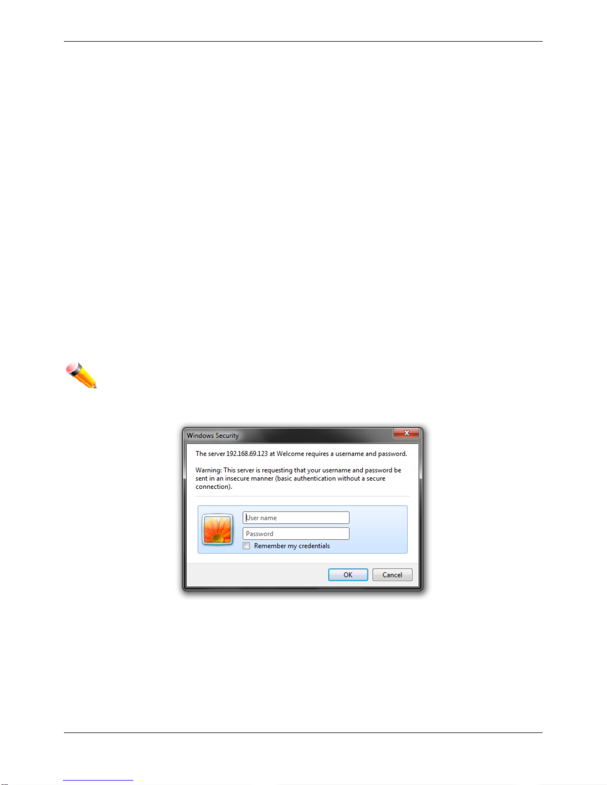
Login to the Web Manager
To begin managing the Switch, simply run the browser installed on your com puter and poi nt it to the IP addres s you
have defined for the device. The URL in the address bar should read something like: http://123.123.123.123, where
the numbers 123 represent the IP address of the Switch.
NOTE: The factory default IP address is 10.90.90.90.
This opens the management module's user authentication window, as seen below.
Figure 1–1 Enter Network Password window
Leave both the User Name field and the Password field blank and click OK. This will open the Web-based user
interface. The Switch management features available in the web-based manager are explained below.
Web-based User Interface
The user interface provides access to various Switch configuration and management windows, allows you to view
performance statistics, and permits you to graphically monitor the system status.
xStack® DGS-3120 Series Managed Switch Web UI Reference Guide
3
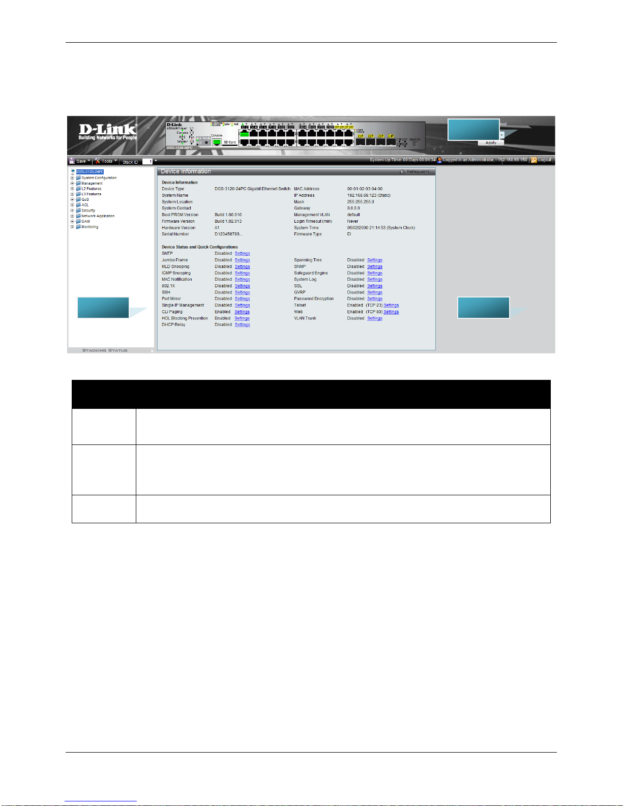
Areas of the User Interface
The figure below shows the user interface. Three distinct areas divide the user interface, as described in the table.
Figure 1–2 Main Web-Manager page
Area
Number
Function
Area 1
Select the menu or window to display. Open folders and click the hyperlinked menu buttons
and subfolders contained within them to display menus. Click the D-Link logo to go to the D-
Link website.
Area 2
Presents a graphical near real-time image of the front panel of the Switch. This area displays
the Switch's ports, console and management port, showing port activity.
Some management functions, including save, reboot, download and upload are accessible
here.
Area 3
Presents switch information based on user selection and the entry of configuration data.
ARE A 2
ARE A 1
ARE A 3

xStack® DGS-3120 Series Managed Switch Web UI Reference Guide
4
Web Pages
When connecting to the management mode of the Switch with a web browser, a login screen is displayed. Enter a
user name and password to access the Switch's management mode.
Below is a list of the main folders available in the Web interface:
System Configuration - In this section the user will be able to configure features regarding the Switch’s
configuration.
Management - In this section the user will be able to configure features regarding the Switch’s management.
L2 Features - In this section the user will be able to configure features regarding the Layer 2 functionality of the
Switch.
L3 Features - In this section the user will be able to configure features regarding the Layer 3 functionality of the
Switch.
QoS - In this section the user will be able to configure features regarding the Quality of Service functionality of the
Switch.
ACL - In this section the user will be able to configure features regarding the Access Control List functionality of the
Switch.
Security - In this section the user will be able to configure features regarding the Switch’s security.
Network Application - In this section the user will be able to configure features regarding network applications
handled by the Switch.
OAM - In this section the user will be able to configure features regarding the Switch’s operations, administration
and maintenance (OAM).
Monitoring - In this section the user will be able to monitor the Switch’s configuration and statistics.
NOTE: Be sure to configure the user name and password in the User Accounts menu before
connecting the Switch to the greater network.
xStack® DGS-3120 Series Managed Switch Web UI Reference Guide
5
Chapter 2 System Configuration
Device Information
System Information Settings
Port Configuration
PoE
Serial Port Settings
Warning Temperature Settings
System Log configuration
Time Range Settings
Port Group Settings (EI Mode Only)
Time Settings
User Accounts Settings
Command Logging Settings
Stacking
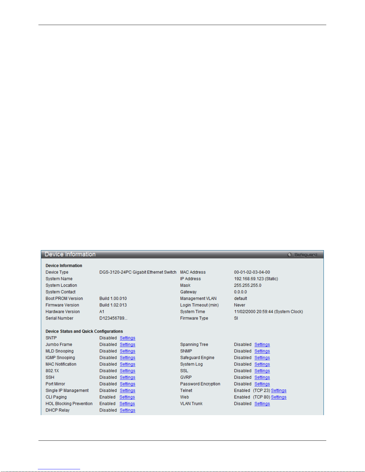
Device Information
This window contains the main settings for all the major functions for the Switch. It appears automatically when you
log on to the Switch. To return to the Device Information window after viewing other windows, click the DGS-3120
Series link.
The Device Information window shows the Switch’s M AC Addres s (as sign ed b y the fac tory and unchangeable), the
Boot PROM Version, Firmware Version, Hardware Version, and many other important types of information. This is
helpful to keep track of PROM and firmware updates and to obtain the Switch’s MAC address for entry into another
network device’s address table, if necessary. In addition, this window displays the status of functions on the Switch
to quickly assess their current global status.
Many functions are hyper-linked for easy access to enable quick configuration from this window.
Figure 2–1 Device Information window (SI Mode Only)
xStack® DGS-3120 Series Managed Switch Web UI Reference Guide
6
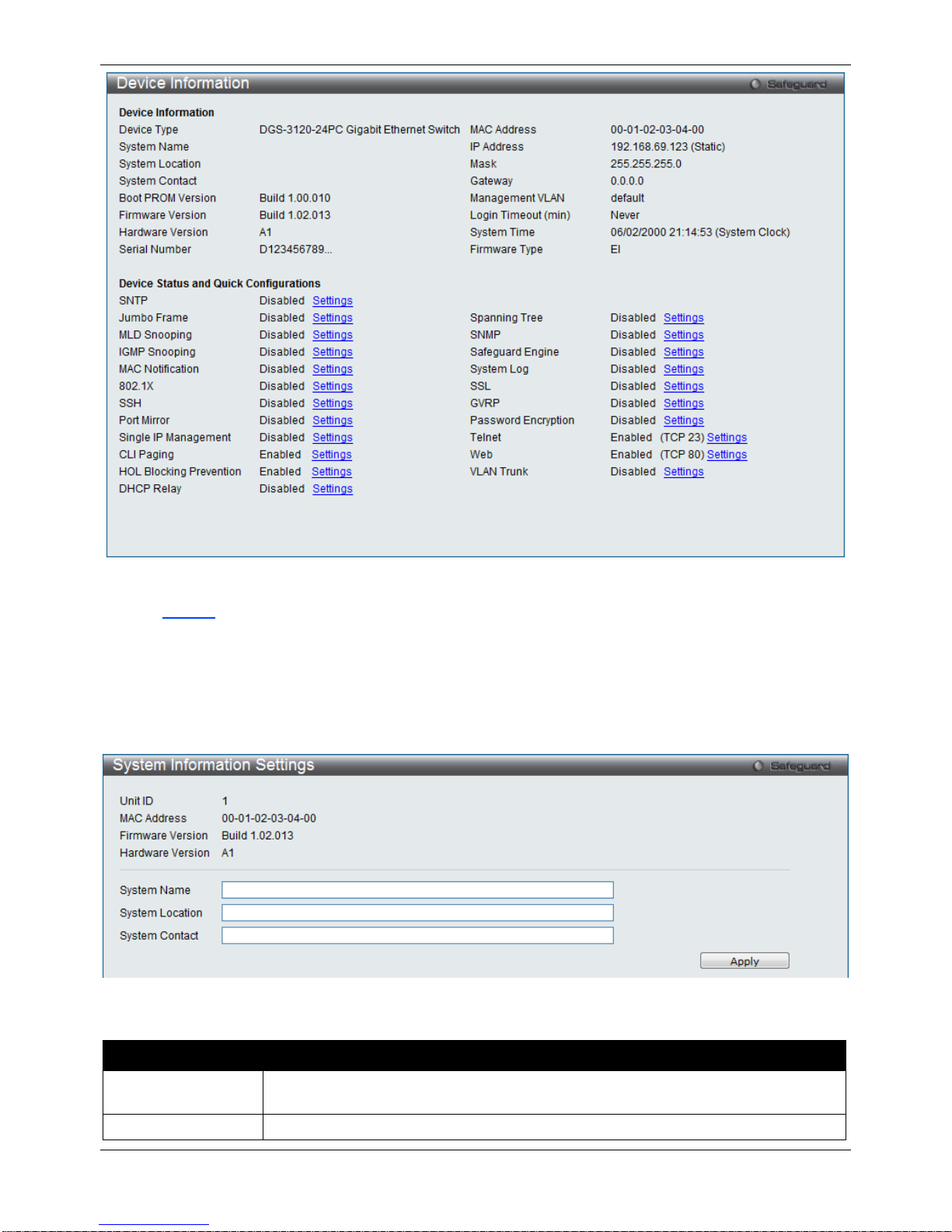
Figure 2–2 Device Information window (EI Mode Only )
Click the
Settings
link to navigate to the appropriate feature page for configuration.
System Information Settings
The user can enter a System Name, System Location, and System Contact to aid in defining the Switch.
To view the following window, click System Configuration > System Information Settings, as show below:
Figure 2–3 System Information Settings window
The fields that can be configured are described below:
Parameter Description
System Name
Enter a system name for the Switch, if so desired. This name will identify it in the
Switch network.
System Location
Enter the location of the Switch, if so desired.
xStack® DGS-3120 Series Managed Switch Web UI Reference Guide
7
System Contact
Enter a contact name for the Switch, if so desired.
Click the Apply button to implement changes made.
Port Configuration
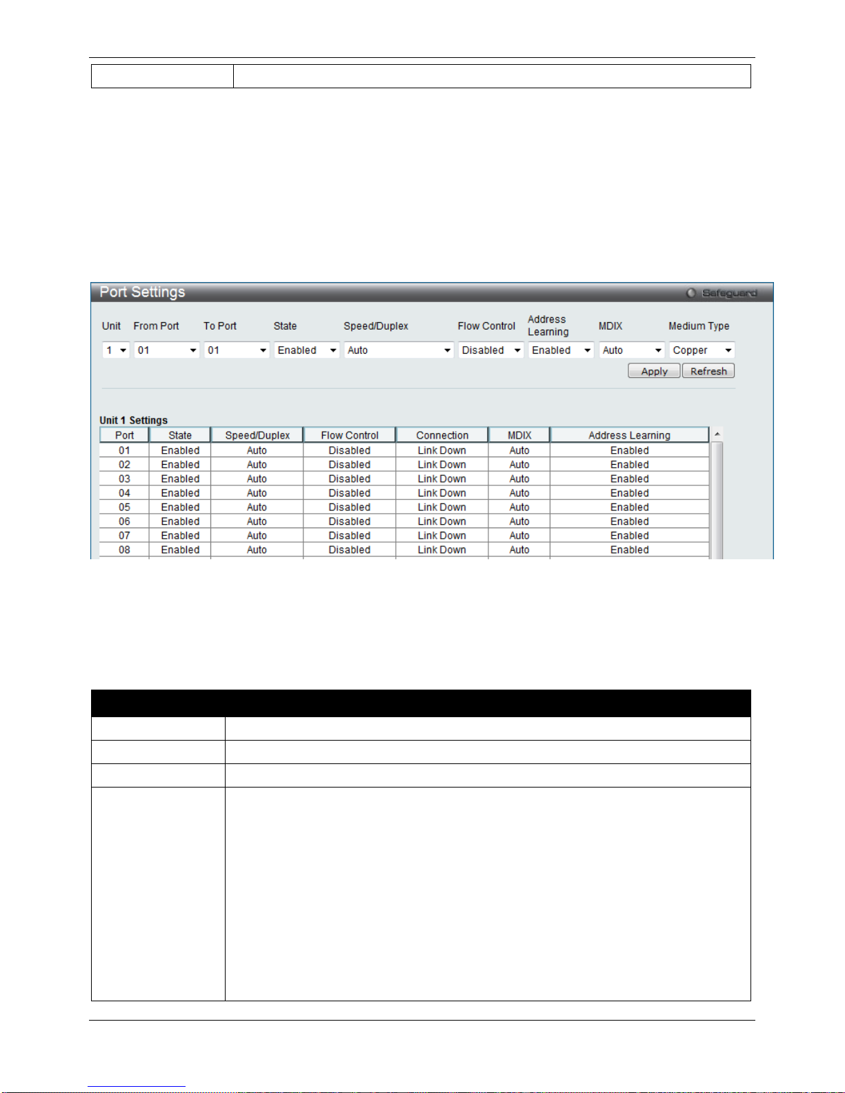
Port Settings
This page used to configure the details of the switch ports.
To view the following window, click System Configuration > Port Configuration > Port Settings, as show below:
Figure 2–4 Port Settings window
To configure switch ports:
1. Choose the port or sequential range of ports using the From Port and To Port pull-down menus.
2. Use the remaining pull-down menus to configure the parameters described below:
The fields that can be configured are described below:
Parameter Description
Unit
Select the unit you wish to configure.
From Port / To Port
Select the appropriate port range used for the configuration here.
State
Toggle the State field to either enable or disable a given port or group of ports.
Speed/Duplex
Toggle the Speed/Duplex field to select the speed and full-duplex/half-duplex state of the
port. Auto denotes auto-negotiation among 10, 100 and 1000 Mbps devices, in full- or
half-duplex (except 1000 Mbps which is always full duplex). The Auto setting allows the
port to automatically determine the fastest settings the device the port is connected to
can handle, and then to use those settings. The other options are 10M Half, 10M Full,
100M Half, 100M Full, 1000M Full_Master, 1000M Full_Slave, and 1000M Full. There is
no automatic adjustment of port settings with any option other than Auto.
The Switch allows the user to configure three types of gigabit connections; 1000M
Full_Master, 1000M Full_Slave, and 1000M Full. Gigabit connections only support full
duplex connections and take on certain characteristics that are different from the other
choices listed.
xStack® DGS-3120 Series Managed Switch Web UI Reference Guide
8
The 1000M Full_Master and 1000M Full_Slave parameters refer to connections running
a 1000BASE-T cable for connection between the Switch port and other device capable
of a gigabit connection. The master setting (1000M Full_Master) will allow the port to
advertise capabilities related to duplex, speed and physical layer type. The master
setting will also determine the master and slave relationship between the two connected
physical layers. This relationship is necessary for establishing the timing control between
the two physical layers. The timing control is set on a master physical layer by a local
source. The slave setting (1000M Full_Slave) uses loop timing, where the timing comes
from a data stream received from the master. If one connection is set for 1000M
Full_Master, the other side of the connection must be set for 1000M Full_Slave. Any
other configuration will result in a link down status for both ports.
Flow Control
Displays the flow control scheme used for the various port configurations. Ports
configured for full-duplex use 802.3x flow control, half-duplex ports use backpressure
flow control, and Auto ports use an automatic selection of the two. The default is
Disabled.
Connection
Here the current connection speed will be displayed.
MDIX Auto - Select auto for auto sensing of the optimal type of cabling.
Normal - Select normal for normal cabling. If set to normal state, the port is in MDI mode
and can be connected to a PC NIC using a straight-through cable or a port (in MDI
mode) on another switch through a cross-over cable.
Cross - Select cross for cross cabling. If set to cross state, the port is in MDIX mode, and
can be connected to a port (in MDI mode) on another switch through a straight cable.
Address Learning Enable or disable MAC address learning for the selected ports. When Enabled,
destination and source MAC addresses are automatically listed in the forwarding table.
When address learning is Disabled, MAC addresses must be manually entered into the
forwarding table. This is sometimes done for reasons of security or efficiency. See the
section on Forwarding/Filtering for information on entering MAC addresses into the
forwarding table. The default setting is Enabled.
Medium Type
If configuring the Combo ports, this defines the type of transport medium to be used.
Click the Apply button to implement changes made.
Click the Refresh button to refresh the display section of this page.
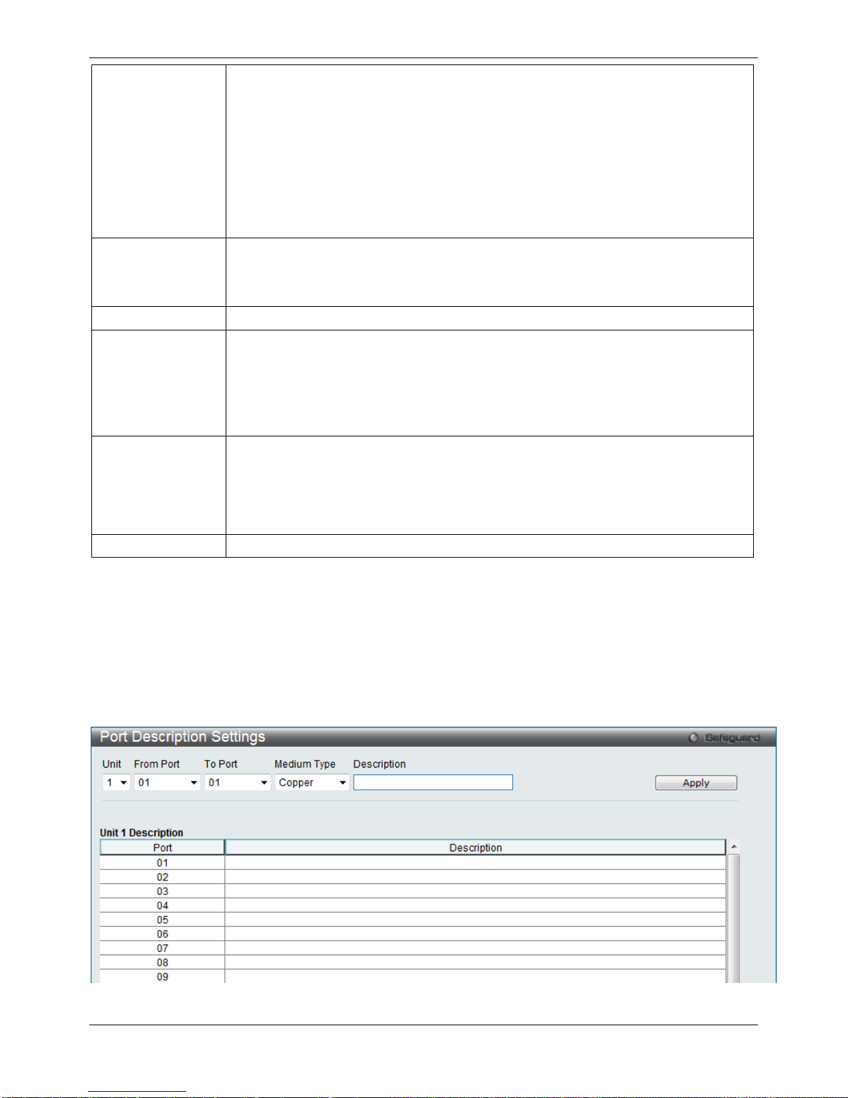
Port Description Settings
The Switch supports a port description feature where the user may name various ports.
To view the following window, click System Configuration > Port Configuration > Port Description Settings, as
show below :
Figure 2–5 Port Description Settings window
xStack® DGS-3120 Series Managed Switch Web UI Reference Guide
9
The fields that can be configured are described below:
Parameter Description
Unit
Select the unit you wish to configure.
From Port / To Port
Select the appropriate port range used for the configuration here.
Medium Type
Specify the medium type for the selected ports. If configuring the Combo ports, the
Medium Type defines the type of transport medium to be used, whether Copper or Fiber.
Description
Users may then enter a description for the chosen port(s).
Click the Apply button to implement changes made.
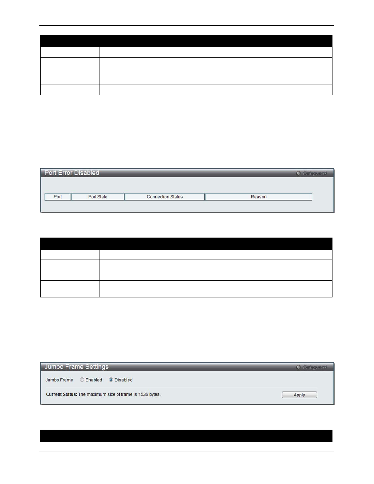
Port Error Disabled
The following window displays the information about ports that have been disconnected by the Switch when a
packet storm occurs or a loop was detected.
To view the following window, click System Configuration > Port Configuration > Port Error Disabled, as show
below:
Figure 2–6 Port Error Disabled
The fields that can be displayed are described below:
Parameter Description
Port
Display the port that has been error disabled.
Port State
Describe the current running state of the port, whether enabled or disabled.
Connection Status
Display the uplink status of the individual ports, whether enabled or disabled.
Reason
Describe the reason why the port has been error-disabled, such as it has become a
shutdown port for storm control.
Jumbo Frame Settings
The Switch supports jumbo frames. Jumbo frames are Ethernet frames with more than 1,518 bytes of payload. The
Switch supports jumbo frames with a maximum frame size of up to 13312 bytes.
To view the following window, click System Configuration > Port Configuration > Jumbo Frame Settings, as
show below :
Figure 2–7 Jumbo Frame Settings window
The fields that can be configured are described below:
Parameter Description

xStack® DGS-3120 Series Managed Switch Web UI Reference Guide
10
Jumbo Frame
Use the radio buttons to enable or disable the Jumbo Frame function on the Switch. The
default is Disabled. When disabled, the maximum frame size is 1536 bytes. When
enabled, the maximum frame size is 13312 bytes.
Click the Apply button to implement changes made.
PoE
The DGS-3120-24PC and DGS-3120-48PC switc hes suppor t Power over Ethernet (PoE) as defined by the IEEE
802.3af and 802.3at. All ports can support PoE up to 30W. Ports 1-24 can supply about 48 VDC power to Powered
Devices (PDs) over Category 5 or Category 3 UTP Ethernet cables. The Switch follows the standard PSE (Power
Sourcing Equipment) pinout Alternative A, whereby power is sent out over pins 1, 2, 3 and 6. The Switches work
with all D-Link 802.3af capable devices.
The Switch includes the following PoE features:
• Auto-discovery recognizes the connection of a PD (Powered Device) and automatically sends power to it.
• The Auto-disable feature occurs under two conditions: firstly, if the total power consumption exceeds the
system power limit; and secondly, if the per port power consumption exceeds the per port power limit.
• Active circuit protection automatically disables the port if there is a short. Other ports will remain active.
Based on 802.3af/at PDs receive power according to the following classification:
Class Maximum power available to PD
0 15.4W
1 4.0W
2 7.0W
3 15.4W
4 15.4W
To configure the PoE features on the Switch, click System Configuration > PoE. The PoE System Settings
window is used to assign a power limit and power disconnect method for the whole PoE system. To configure the
Power Limit for the PoE system, enter a value between 1W and 370W for the Switch in the Power Limit field.
When the total consumed power exceeds the power limit, the PoE controller (located in the PSE) disconnects the
power to prevent overloading the power supply.
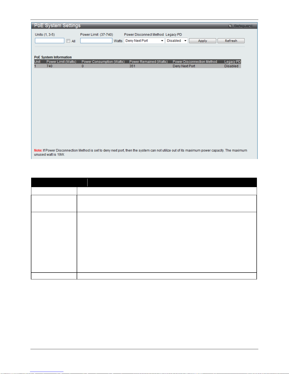
PoE System Settings
To view the following window, click System Configuration > PoE > PoE System Settings, as show below:
PSE provides power according to the following classification:
Class Max power used by PSE
0 16.2W
1 4.2W
2 7.4W
3 16.2W
User define 31.2W
xStack® DGS-3120 Series Managed Switch Web UI Reference Guide
11
Figure 2–8 PoE System Settings window
The following parameters can be configured:
Parameter Description
Unit
Select the unit you wish to configure. Tick the All check box to select all units.
Power Limit (37-
740)
Sets the limit of power to be used from the Switch’s power source to PoE ports. The user
may configure a Power Limit between 37W and 740W for the DGS-3120-24PC and
DGS-3120-48PC. The default setting is 740W.
Power Disconnect
Method
The PoE controller uses either Deny Next Port or Deny Low Priority Port to offset the
power limit being exceeded and keeps the Switch’s power at a usable level. Use the drop
down menu to select a Power Disconnect Method. The default Power Disconnect
Method is Deny Next Port. Both Power Disconnection Methods are described below:
Deny Next Port – After the power limit has been exceeded, the next port attempting to
power up is denied, regardless of its priority. If Power Disconnection Method is set to
Deny Next Port, the system cannot utilize out of its maximum power capacity. The
maximum u nused watt is 19W.
Deny Low Priority Port – After the power limit has been exceeded, the next port
attempting to power up causes the port with the lowest priority to shut down so as to
allow the high-priority and critical priority ports to power up.
Legacy PD
Use the drop-down menu to enable or disable detecting legacy PDs signal.
Click Apply to implement changes made.
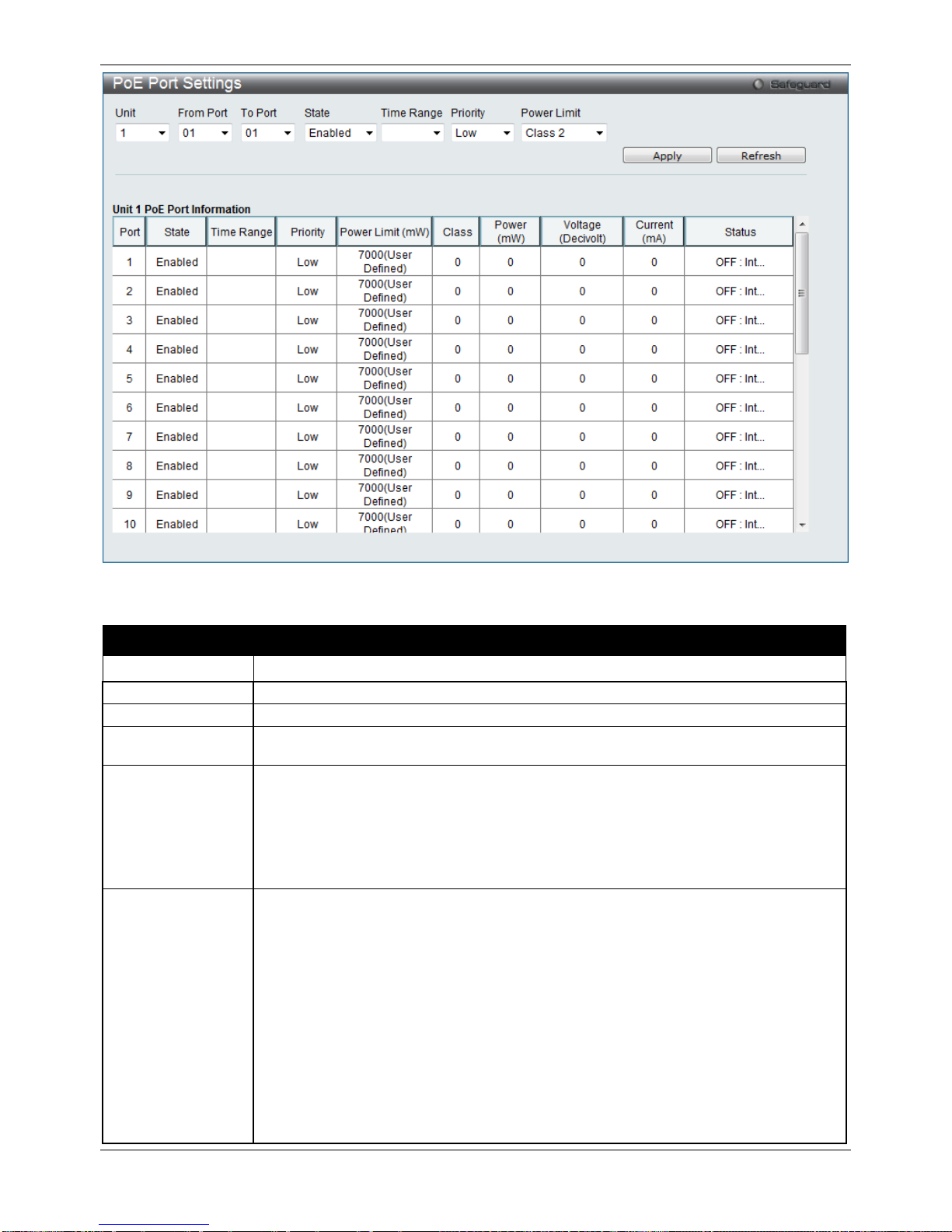
PoE Port Settings
To view the following window, click System Configuration > PoE > PoE Port Settings, as show below:
xStack® DGS-3120 Series Managed Switch Web UI Reference Guide
12
Figure 2–9 PoE Port Settings window
The following parameters can be configured:
Parameter Description
Unit
Select the unit you wish to configure.
From Port / To Port
Select a range of ports from the pull-down menus to be enabled or disabled for PoE.
State
Use the pull-down menu to enable or disable ports for PoE.
Time Range
Select a range of the time to the port set as POE. If Time Range is configured, the power
can only be supplied during the specified period of time.
Priority
Use the pull-down menu to select the priority of the PoE ports. Port priority determines
the priority which the system attempts to supply the power to the ports. There are three
levels of priority that can be selected, Critical, High, and Low. When multiple ports
happen to have the same level of priority, the port ID will be used to determine the
priority. The lower port ID has higher priority. The setting of priority will affect the order of
supplying power. Whether the disconnect method is set to deny low priority port, the
priority of each port will be used by the system to manage the supply of power to ports.
Power Limit
This function is used to configure the per-port power limit. If a port exceeds its power
limit, it will shut down.
Based on 802.3af/802.3at, there are different PD classes and power consumption
ranges;
Class 0 – 0.44~15.4W
Class 1 – 0.44~4.0W
Class 2 – 4~7.0W
Class 3 – 7~15.4W
Class 4 – 15.4W
The following is the power limit applied to the port for these five classes. For each class,
the power limit is a little more than the power consumption range for that class. This
takes into account any power loss on the cable. Thus, the following are the typical
values;
xStack® DGS-3120 Series Managed Switch Web UI Reference Guide
13
Class 0 – 16200mW
Class 1 – 4200mW
Class 2 – 7400mW
Class 3 – 16200mW
User Define – 35000mW
Click Apply to implement changes made. The port status of all PoE configured ports is displayed in the table in the
bottom half of the screen shown above.
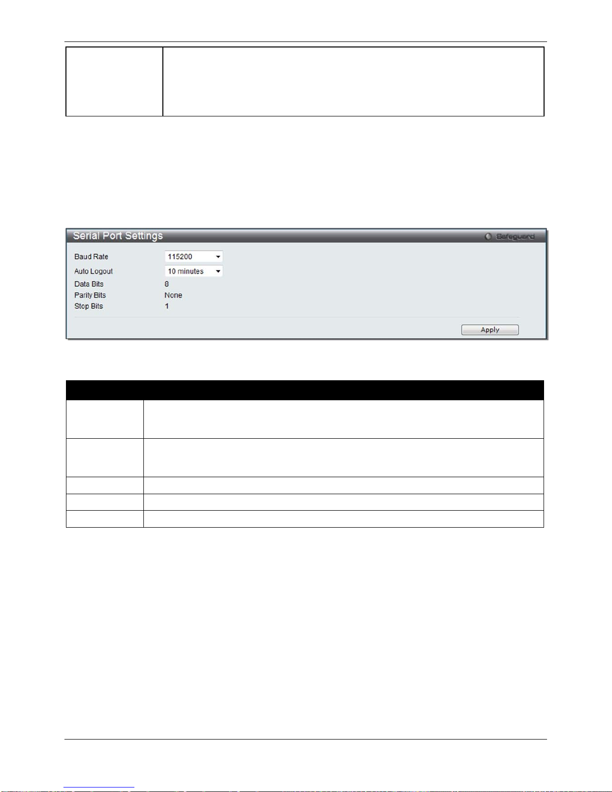
Serial Port Settings
This window allows the user to adjust the Baud Rate and the Auto Logout values.
To view the following window, click System Configuration > Serial Port Settings, as show below:
Figure 2–10 Serial Port Settings window
The fields that can be configured are described below:
Parameter Description
Baud Rate
Specify the baud rate for the serial port on the Switch. There are four possible baud rates to
choose from, 9600, 19200, 38400 and 115200. For a connection to the Switch using the
console port, the baud rate must be set to 115200, which is the default setting.
Auto Logout
Select the logout time used for the console interface. This automatically logs the user out
after an idle period of time, as defined. Choose from the following options: 2, 5, 10, 15
minutes or Never. The default setting is 10 minutes.
Data Bits
Display the data bits used for the serial port connection.
Parity Bits
Display the parity bits used for the serial port connection.
Stop Bits
Display the stop bits used for the serial port connection.
Click the Apply button to implement changes made.
Warning Temperature Settings
This window allows the user to configure the system warning temperature parameters.
To view the following window, click System Configuration > Warning Temperature Se ttings, as show below:
xStack® DGS-3120 Series Managed Switch Web UI Reference Guide
14
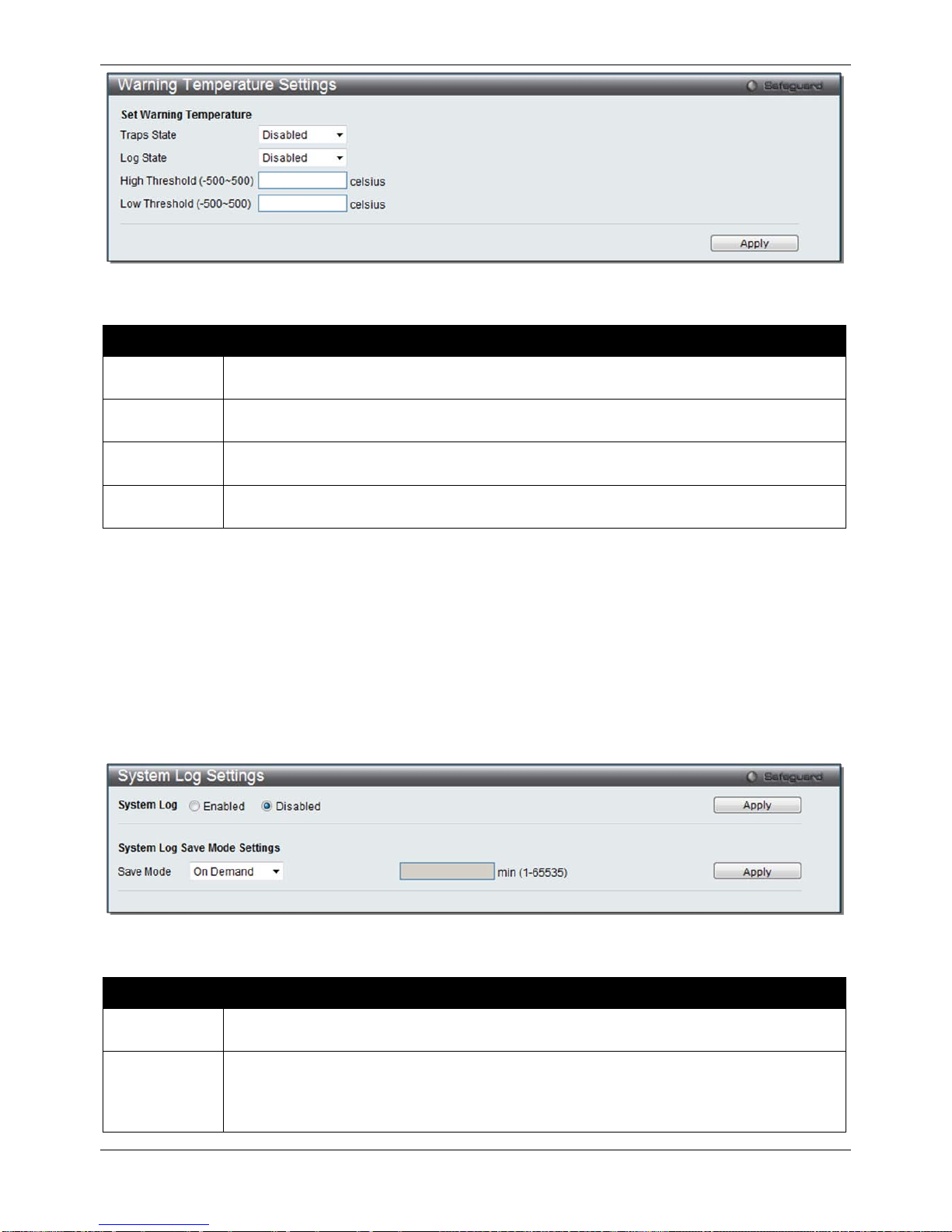
Figure 2–11 Warning Temperature Settings windo w
The fields that can be configured are described below:
Parameter Description
Traps State
Use the drop-down menu to enable or disable the traps state option of the warning
temperature setting.
Log State
Use the drop-down menu to enable or disable the log state opti on of the warn ing temperature
setting.
High
Threshold
Enter the high threshold value of the warning temperature setting.
Low
Threshold
Enter the low threshold value of the warning temperature setting.
Click the Apply button to implement changes made.
System Log configuration
System Log Settings
The Switch allows users to choose a method for which to save the switch log to the flash memory of the Switch.
To view the following window, click System Configuration > System Log Configuration > System Log Settings,
as show below:
Figure 2–12 System Log Settings window
The fields that can be confi gured ar e desc r ibed belo w:
Parameter Description
System Log Use the radio buttons to enable or disable the system log settings. Click the Apply button to
accept the changes made.
Save Mode
Use the pull-down menu to choose the method for saving the switch log to the flash memory.
The user has three options:
On Demand – Users who choose this method will only save log files when they manually tell
the Switch to do so, either using the Save Log link in the Save folder.
xStack® DGS-3120 Series Managed Switch Web UI Reference Guide
15
Time Interval – Users who choose this method can configure a time interval by which the
Switch will save the log files, in the box adjacent to this configuration field. The user may set
a time between 1 and 65535 minutes.
Log Trigger – Users who choose this method will have log files saved to the Switch every
time a log event occurs on the Switch.
Click the Apply button to accept the changes made.
System Log Server Settings
The Switch can send System log messages to up to four designated servers using the System Log Server.
To view the following window, click System Configuration > System Log Configuration > System Log Server
Settings, as show below:
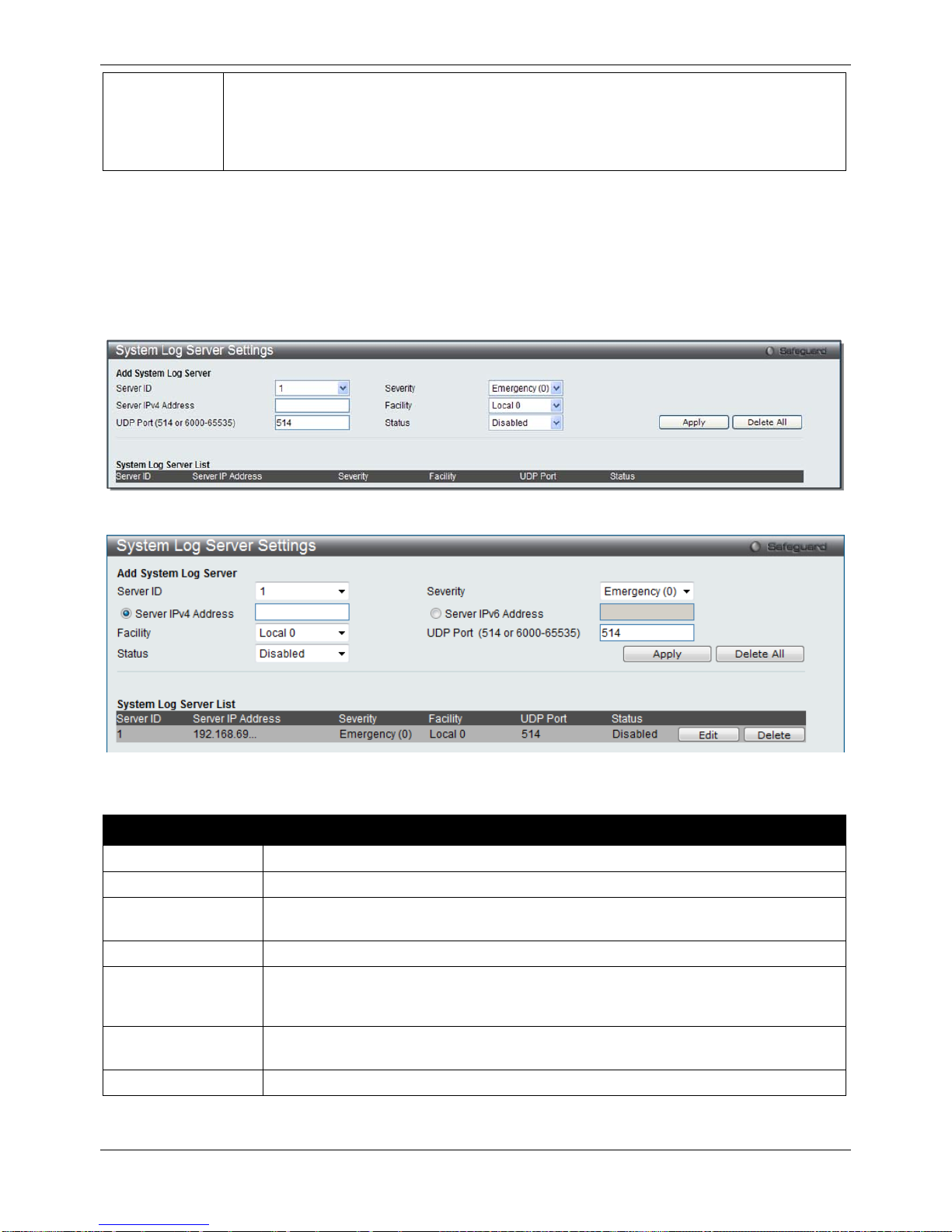
Figure 2–13 System Log Server Settings (SI Mode Only)
Figure 2–14 System Log Server Settings (EI Mode Only)
The fields that can be configured are described below:
Parameter Description
Server ID
Syslog server settings index (1 to 4).
Server IPv4 Address
The IPv4 address of the Syslog server.
Server IPv6 Address
(EI Mode Only)
The IPv6 address of the Syslog server.
UDP Port
Type the UDP port number used for sending Syslog messages. The default is 514.
Severity
Use the drop-down menu to select the higher level of messages that will be sent. All
messages which level is higher than selecting level will be sent. The options are
Emergency, Alert, Critical, Error, Warning, Notice, Informational and Debug.
Facility Use the drop-down menu to select Local 0, Local 1, Local 2, Local 3, Local 4, Local 5,
Local 6, or Local 7.
Status
Choose Enabled or Disabled to activate or deactivate.
Click the Apply button to accept the changes made.
Click the Edit button to re-configure the specific entry.

xStack® DGS-3120 Series Managed Switch Web UI Reference Guide
16
Click the Delete button to remove the specific entry.
Click the Delet e All button to remove all servers configured.
System Log
Users can view and delete the local histor y log as compiled b y the Switc h's m anagement agent.
To view the following window, click System Configuration > System Log Configuration > System Log, as show
below:
Figure 2–15 System Log window
The Switch can record event information in its own log. Click Go to go to the next page of the System Log window.
The fields that can be configured are described belo w:
Parameter Description
Log Type
In the drop-down menu the user can select the log type that will be displayed.
Severity - When selecting Severity from the drop-down menu, a secondary tick must be
made. Secondary ticks are Emergency, Alert, Critical, Error, Warning, Notice,
Informational and Debug. To view all information in the log, simply tick the All check box.
Module List - When selecting Module List, the module name must be manually entered.
Available modules are MSTP, ERROR_LOG, CFM_EXT, and ERPS.
Attack Log - When selecting Attack Log all attacks will be listed.
Index
A counter incremented whenever an entry to the Switch's history log is made. The table
displays the last entry (highest sequence number) first.
Time
Display the time in days, hours, minutes, and seconds since the Switch was last restarted.
Level
Display the level of the log entry.
Log Text
Display text describing the event that triggered the history log entry.
Click the Find button to dis play the log in the display section according to the selection made.
Click the Clear Log button to clear the entries from the log in the display section.
Click the Clear Attack Log button to clear the entries from the attack log in the display section.
System Log & Trap Settings
The Switch allows users to configure the system log source IP interface addresses here.
To view the following window, click System Configuration > System Log Configuration > System Log & Trap
Settings, as show below:
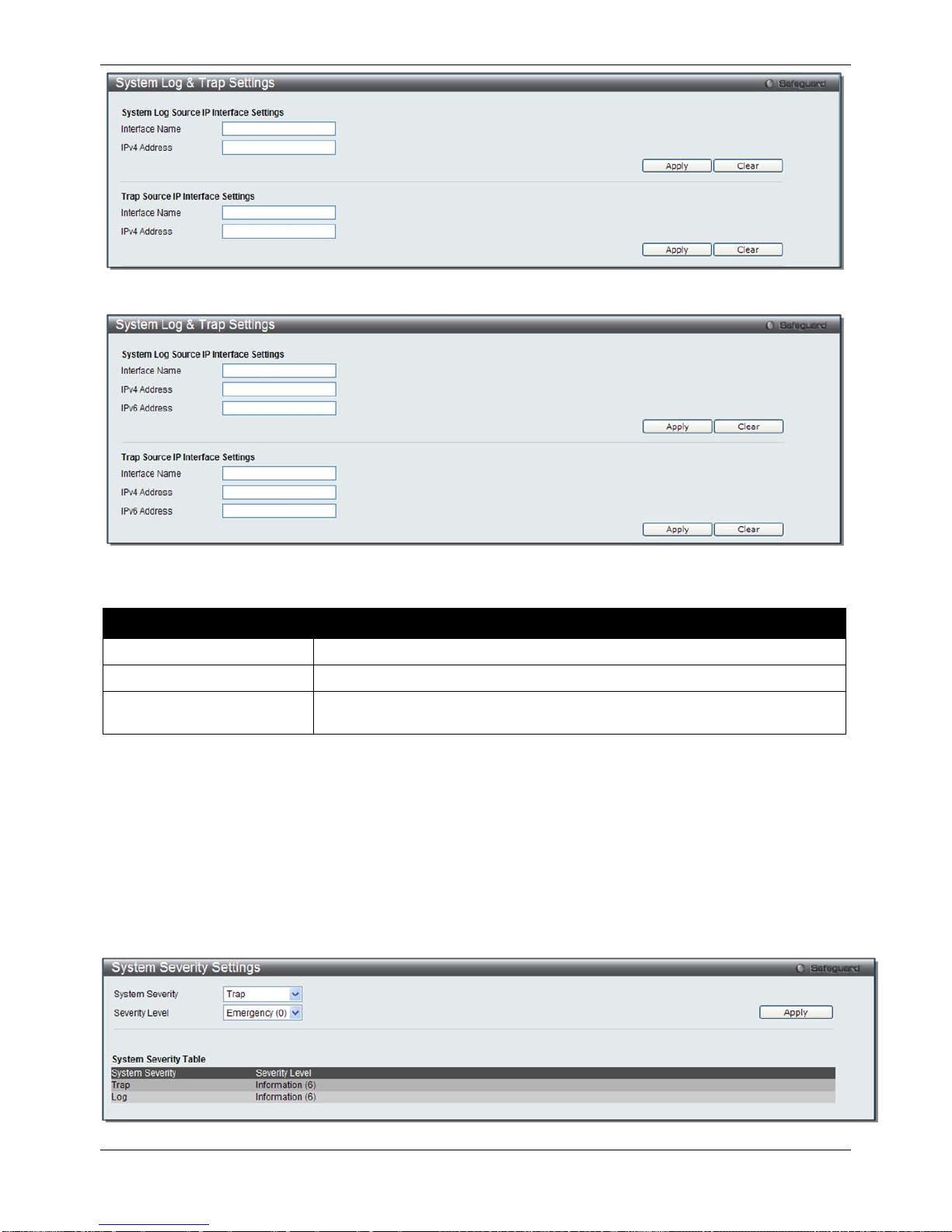
xStack® DGS-3120 Series Managed Switch Web UI Reference Guide
17
Figure 2–16 System Log & Trap Settings window (SI Mode Only)
Figure 2–17 System Log & Trap Settings window (EI Mode Only)
The fields that can be configured are described below:
Parameter Description
Interface Name
Enter the IP interface name used.
IPv4 Address
Enter the IPv4 address used.
IPv6 Address (EI Mode
Only)
Enter the IPv6 address used.
Click the Apply button to accept the changes made.
Click the Clear button to clear all the information entered in the fields.
System Severity Settings
The Switch can be configured to allow alerts be logged or sent as a trap to an SNMP agent. The level at which the
alert triggers either a log entry or a trap message can be set as well. Use the System Severity Settings window to
set the criteria for alerts. The current settings are displayed below the System Severity Table.
To view the following window, click System Configuration > System Log Configuration > System Severity
Settings, as show below:
Figure 2–18 System Severity Settings window
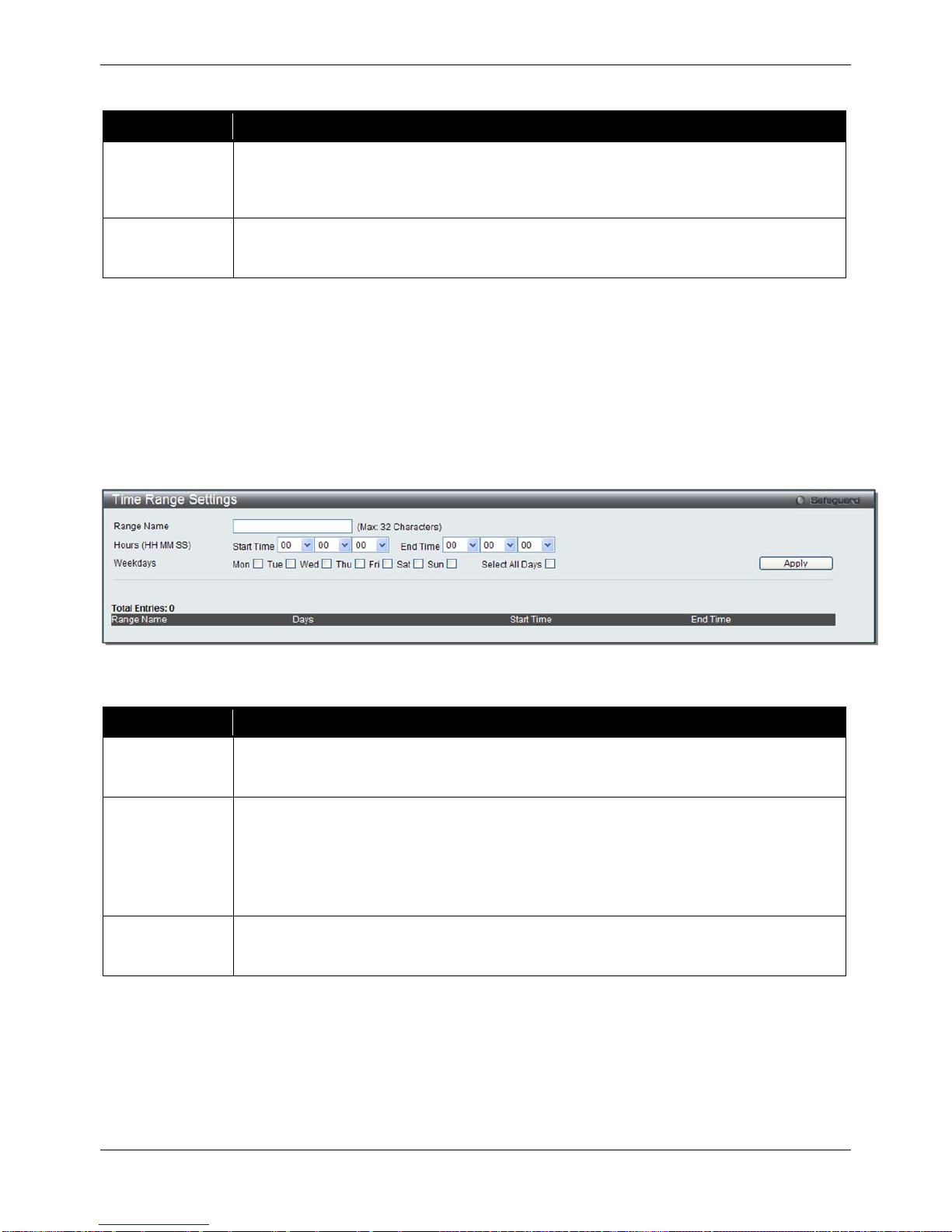
xStack® DGS-3120 Series Managed Switch Web UI Reference Guide
18
The fields that can be configured are described below:
Parameter Description
System Severity Choose how the alerts are used from the drop-down menu. Select Log to send the alert of
the Severity Type configured to the Switch’s log for analysis. Choose Trap to send it to an
SNMP agent for analysis, or select All to send the chosen alert type to an SNMP agent and
the Switch’s log for analysis.
Severity Level
This drop-down menu allows you to select the level of messages that will be sent. The
options are Emergency (0), Alert (1), Critical (2), Error (3), Warning (4), Notice (5),
Information (6) and Debug (7).
Click the Apply button to accept the changes made.
Time Range Settings
Time range is a time period that the respective function will take an effect on, such as ACL. For example, the
administrator can configure the time-based ACL to allow users to surf the Internet on every Saturday and every
Sunday, meanwhile to deny users to surf the Internet on weekdays.
The user may enter up to 64 time range entries on the Switch.
To view the following window, click System Configuration > Time Range Settings, as show below:
Figure 2–19 Time Range Settings window
The fields that can be configured are described below:
Parameter Description
Range Name
Enter a name of no more than 32 alphanumeric characters that will be used to identify this
time range on the Switch. This range name will be used in the Access Profile table to
identify the access profile and associated rule to be enabled during this time range.
Hours
This parameter is used to set the time in the day that this time range is to be enabled using
the following parameters:
Start Time - Use this parameter to identify the starting time of the time range, in hours,
minutes and seconds, based on the 24-hour time system.
End Time - Use this parameter to identify the ending time of the time range, in hours,
minutes and seconds, based on the 24-hour time system.
Weekdays
Use the check boxes to select the corresponding days of the week that this time range is to
be enabled. Tick the Select All Days check box to configure this time range for every day of
the week.
Click the Apply button to accept the changes made. Current config ured entr i es will be displ a yed in the Time
Range Information table in the bottom half of the window shown above.
Port Group Settings (EI Mode Only)
This window is used to create port groups, and add or delete ports from the port groups.
To view the following window, click System Configuration > Port Group Settings, as show below:
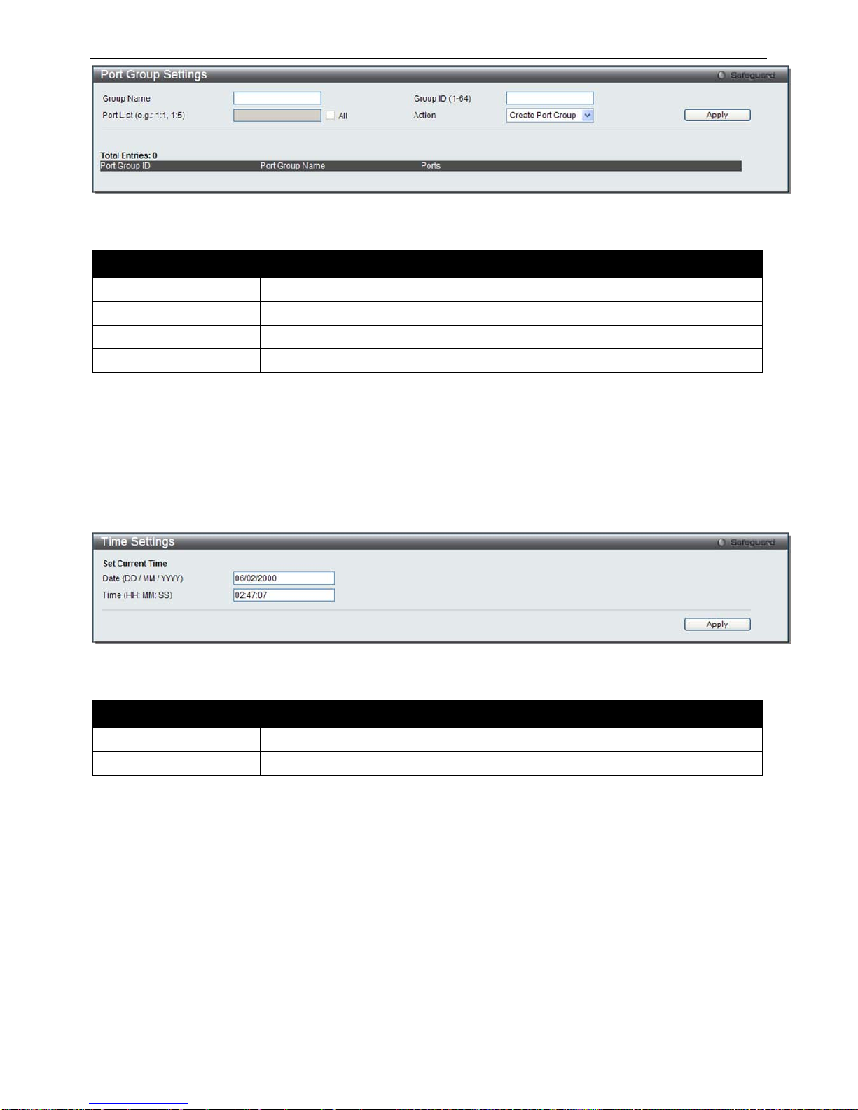
xStack® DGS-3120 Series Managed Switch Web UI Reference Guide
19
Figure 2–20 Port Group Settings window
The fields that can be configured are described below:
Parameter Description
Group Name
Enter the name of a port group.
Group ID (1-64)
Enter the ID of a port group
Port List
Enter a port or list of ports. Tick the
All
check box to apply to all ports.
Action
Use the drop-down menu to select Create Port Group, Add Ports or Delete Ports.
Click the Apply button to accept the changes made.
Click the Delete button to remove the specific entry.
Time Settings
Users can configure the time settings for the Switch.
To view the following window, click System Configuration > Time Settings, as show below:
Figure 2–21 Time Settings window
The fields that can be configured are described below:
Parameter Description
Date (DD/MM/YYYY)
Enter the current day, month, and year to update the system clock.
Time (HH:MM:SS)
Enter the current time in hours, minutes, and seconds.
Click the Apply button to accept the changes made.
User Accounts Settings
The Switch allows the control of user privileges.
To view the following window, click System Configuration > User Accounts Settings, as show below:
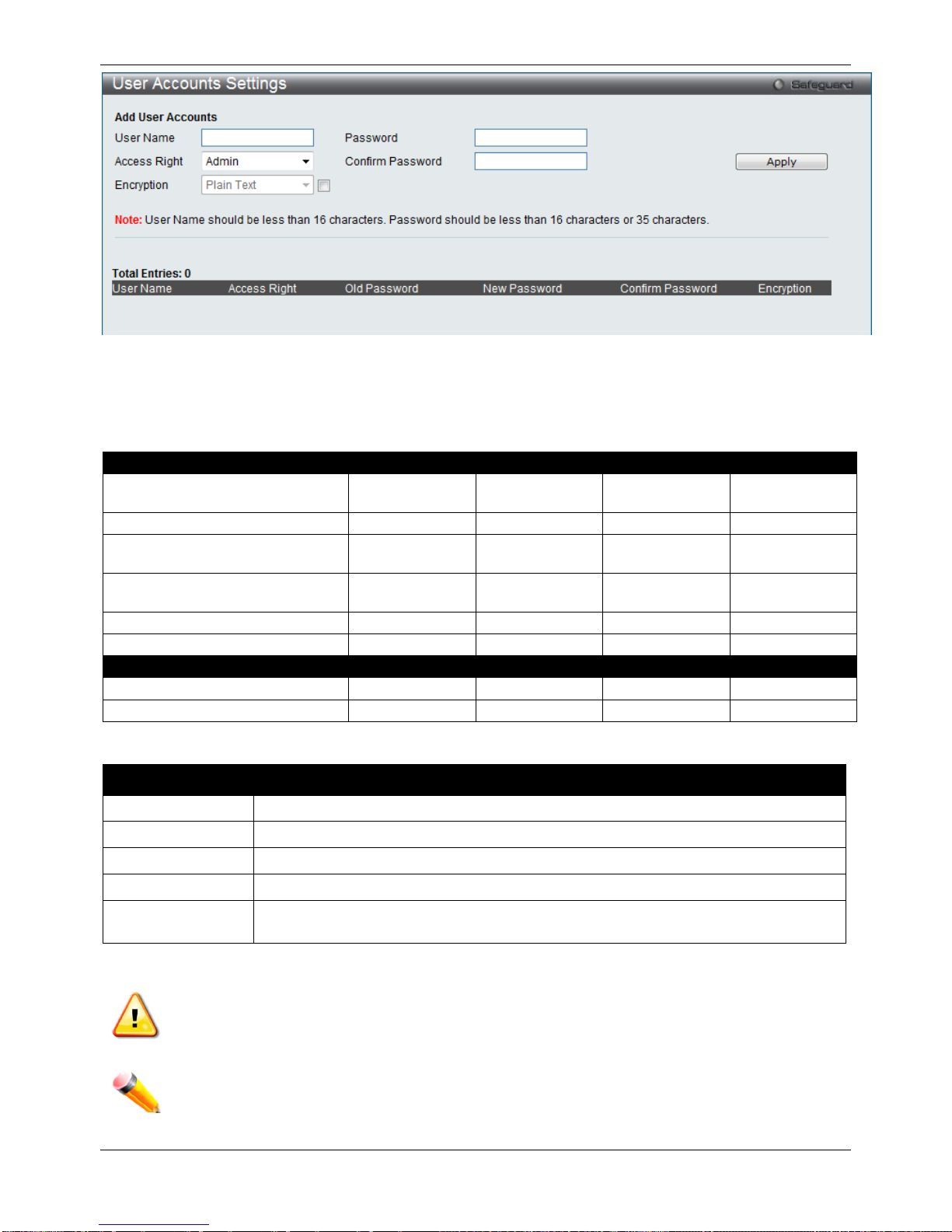
xStack® DGS-3120 Series Managed Switch Web UI Reference Guide
20
Figure 2–22 User Accounts Settings window
To add a new user, type in a User Name and New Pas s wo rd and retype the same password in the Confirm New
Password field. Choose the level of privilege (Admin, Operator, Power User or User) from the Access Right dropdown menu.
Management
Admin
Operator
Power User
User
Configuration Read/Write Read/Write–
partly
Read/Write–
partly
No
Network Monitoring
Read/Write
Read/Write
Read-only
Read-only
Community Strings and Trap
Stations
Read/Write Read-only Read-only Read-only
Update Firmware and
Configuration Files
Read/Write No No No
System Utilities
Read/Write
Read-only
Read-only
Read-only
Factory Reset
Read/Write
No
No
No
User Account Management
Add/Update/Delete User Accounts
Read/Write
No
No
No
View User Accounts
Read/Write
No
No
No
The fields that can be configured are described below:
Parameter Description
User Name
Enter a new user name for the Switch.
Password
Enter a new password for the Switch.
Confirm Password
Re-type in a new password for the Switch.
Access Right
Specify the access right for this user.
Encryption Specifies that encryption will be app lied to this account. Option to choose from are Plain
Text, and SHA-1.
Click the Apply button to accept the changes made.
NOTICE: In case of lost passwords or password corruption, please refer to the appendix chapter
entitled, “Password Recovery Procedure,” which will guide you through the steps necessary to resolve
this issue.
NOTE: The username and password should be less than 16 characters.
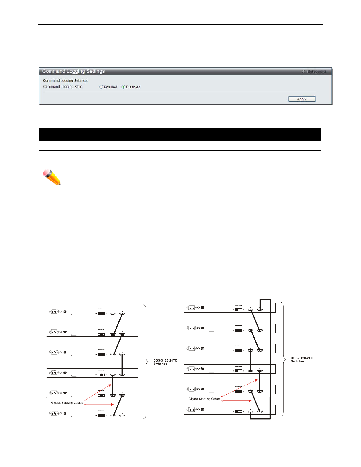
xStack® DGS-3120 Series Managed Switch Web UI Reference Guide
21
Command Logging Settings
This window is used to enable or disable the command logging settings.
To view this window, click System Configuration > Command Logging Settings, as shown below:
Figure 2–23 Command Logging Settings window
The fields that can be configured are described below:
Parameter Description
Command Logging State
Use the radio buttons to enable or disable the function.
Click the Apply button to accept the changes made.
NOTE: When the switch is under the booting procedure, all configuration commands will not be
logged. When the user uses AAA authentication to logged in, the user name should not be
changed if the user has used the Enable Admin function to replace its privilege.
Stacking
From firmware release v1.00 of this Switch, the Switch now supports switch stacking, where a set of six switches
can be combined to be managed by one IP address through Telnet, the GUI interface (web), the console port or
through SNMP. Each switch of this series has two stacking ports located at the rear of the device, which can be
used to connect other devices and make them stack together. After adding these stacking ports, the user may
connect these ports together using copper cables (also sold separately) in one of two possible topologies.
Duplex Chain – As shown in Figure 2–24, The Duplex Chain topology stacks switches together in a chain-link
format. Using this method, data transfer is only possible in one direction and if there is a break in the chain, then
data transfer will obviously be affected.
Duplex Ring – As shown in Figure 2–25, the Duplex Ring stacks switches in a ring or circle format where data
can be transferred in two directions. This topology is very resilient due to the fact that if there is a break in the ring,
data can still be transferred through the stacking cables between switches in the stack.
Figure 2–24 Switches stacked in a Duplex Chain Figure 2–25 Switches stacked in a Duplex Ring

xStack® DGS-3120 Series Managed Switch Web UI Reference Guide
22
Within each of these topologies, each switch plays a role in the Switch stack. These roles can be set by the user
per individual Switch, or if desired, can be automatically determined by the Switch stack. Three possible roles exist
when stacking with the Switch.
Primary Master – The Primary Master is the leader of the stack. It will maintain normal operations, monitor
operations and the running topology of the Stack. This switch will also assign Stack Unit IDs, synchronize
configurations and transmit commands to remaining switches in the switch stack. The Primary Master can be
manually set by assigning this Switch the highest priority (a lower number denotes a higher priority) before
physically assembling the stack, or it can be determined automatically by the stack through an election process
which determines the lowest MAC address and then will assign that switch as the Primary Master, if all priorities
are the same. The Primary master are physically displayed by the seven segment LED to the far right on the f r ont
panel of the switch where this LED will flash between its given Box ID and ‘H’.
Backup Master – The Backup Master is the backup to the Primary Master, and will take over the functions of the
Primary Master if the Primary Master fails or is removed from the Stack. It also monitors the status of neighboring
switches in the stack, will perform commands assigned to it by the Primary Master and will monitor the running
status of the Primary Master. The Backup Master can be set by the user by assigning this Switch the second
highest priority before physically assembling the stack, or it can be determined automatically by the stack through
an election process which determines the second lowest MAC address and then will assign that switch as the
Backup Master, if all priorities are the same. The Backup master are physically displayed by the seven segment
LED to the far right on the front panel of the switch where this LED will flash between its given Box ID and ‘h’.
Slave – Slave switches constitute the rest of the switch stack and although not Primary or Backup Masters, they
can be placed into these roles when these other two roles fail or are removed from the stack. Slave switches
perform operations requested by the master, monitor the status of neighbor switches in the stack and the stack
topology and adhere to the Backup Master’s commands once it becomes a Primary Master. Slave switches will do
a self-check to determine if it is to become the Backup Master if the Backup Master is promoted to the Primary
Master, or if the Backup Master fails or is removed from the switch stack. If both Primary and Backup masters fail,
or are removed from the Switch stack, it will determine if it is to become the Primary Master. These roles will be
determined, first by priority and if the priority is the same, the lowest MAC address.
Once switches have been assembled in the topology desired by the user and powered on, the stack will undergo
three processes until it reaches a functioning state.
Initialization State – This is the first state of the stack, where the runtime codes are set and initialized and the
system conducts a peripheral diagnosis to determine each individual switch is functioning properly.
Master Election State – Once the codes are loaded and initialized, the stack will undergo the Master Election
State where it will discover the type of topology used, elect a Primary Master and then a Backup Master.
Synchronization State – Once the Primary Master and the Backup Master have been established, the Primary
Master will assign Stacking Unit IDs to switches in the stack, synchronize configurations for all switches and then
transmit commands to the rest of the switches based on the users configurations of the Primary Master.
Once these steps have been completed, the switch stack will enter a normal operating mode.
Stack Switch Swapping
The stacking feature of the Switch supports “hot swapping” of switches in and out of the running stack. Users may
remove or add switches to the stack without powering down or largely affecting the transfer of data between
switches in the stack, with a few minor provisions.
When switches are “hot inserted” into the running stack, the new switch may take on the Primary Master, Backup
Master or Slave role, depending on configurations set on the newly added switch, such as configured priority or
MAC address. Yet, if adding two stacks together that have both previously undergone the election process, and
therefore both have a Primary Master and a Backup master, a new Primary Master will be elected from one of the
already existing Primar y Masters , based on prior it y or MAC addr es s. This Primary Master will take over all of the
Primary Master’s roles for all new switches that were hot inserted. This process is done using discovery packets
that circulate through the switch stack every 1.5 seconds until the discovery process has been completed.
The “hot remove” action means removing a device from the stack while the stack is still running. The hot removal is
detected by the stack when it fails to receive heartbeat packets during its specified interval from a device, or when
one of the stacking ports links is down. Once the device has been removed, the remaining switches will update
their stacking topology database to reflect the change. Any one of the three roles, Primary Master, Backup Master
or Slave, may be removed from the stack, yet different processes occur for each specific device removal.
If a Slave device has been removed, the Primary Master will inform other switches of the hot remove of this dev ice
through the use of unit leave messages. Switches in the stack will clear the configurations of the unit removed, and
dynamically learned databases, such as ARP, will be cleared as well.
 Loading...