

Page 1
Page 2

Table of Contents
D-Link DES-3010FA/GA User Guide Overview...............................................................................7
Using the Installation Guide.............................. .........................................................................................7
Using the Embedded Web Interface User Guide.......................................................................................7
Intended Audience...........................................................................................................................8
D-Link DES 3010FA/GA Installation Guide...................................................................................9
Device Description................................................................................................................ 10
Viewing the Device........................................................................................................................11
DES-3010FA Front Panel........................................................................................................................11
DES-3010GA Front Panel .......................................................................................................................11
Ports Description ...........................................................................................................................13
10/100Base-TX Fast Ethernet Ports.......................................................................................................13
1000Base-T Gigabit Ethernet Ports.........................................................................................................13
100Base-FX Fiber Ports..........................................................................................................................13
SFP Port..................................................................................................... .. ...........................................13
DB-9 Console Port............................................................... ....................................................................14
Cable Specifications......................................................................................................................15
LED Defiitions................................................................................................................................16
Port LEDs ................................................................................................................................................16
Power LED...............................................................................................................................................19
Console LED....................................... .. ...................................................................................................19
Cable, Port, and Pinout Information ................. ... ... ... .... ... ... ... .... ... ... ... ... .... ... ... ... .... ... ...................20
Pin Connections for the 10/100/1000 Ethernet Interface.........................................................................20
Physical Dimensions .....................................................................................................................21
Mounting Device................................................................................................................... 22
Preparing for Installation................................................................................................................23
Installation Precautions............................................................................................................................23
Site Requirements...................................................................................................................................23
Unpacking ................................................................................................................................................24
Installing the Device ......................................................................................................................25
Desktop or Shelf Installation....................................................................................................................25
Rack Installation ......................................................................................................................................25
Wall Installation........................................ ................................................................................................28
Connecting the Device .............. ... .... ............................................. ... ... ... .... ... ................................29
Connecting the Switch to a Terminal.......................................................................................................29
AC Power Connection .............................................................................................................................30
Starting and Configuring the Device.....................................................................................31
Configuring the Terminal ...............................................................................................................32
Installation Procedure....................................................................................................................32
Device Port Default Settings....................................................................................................................32
Page 1
Page 3

D-Link DES-3010FA/GA User Guide
Booting the Device........................................................................................................................ 33
Configuration Overview....................................... .... ... ... ... .... ... ... ................................................... 34
Initial Configuration................................................................................................................................. 34
Advanced Configuration................................................................................................................ 39
Receiving an IP Address from a DHCP Server....................................................................................... 39
Receiving an IP Address from a BOOTP Server.................................................................................... 39
Security Management and Password Configuration............................................................................... 40
Startup Procedures....................................................................................................................... 43
Startup Menu Procedures....................................................................................................................... 43
Software Download and Reboot............................................................................................................. 44
D-Link DES 3010FA/GA EWS User Guide................................................................................. 48
Getting Started...................................................................................................................... 49
Starting the D-Link Embedded Web Interface............................................................................... 50
Understanding the D-Link Embedded Web Interface.................................................................... 51
Device Representation............................................................................................................................ 53
Using the D-Link Embedded Web Interface Management Buttons........................................................53
Using Screen and Table Options..................................................................................................54
Adding Configuration Information .......................................................... .................................................54
Modifying Configuration Information .......................................................................................................54
Deleting Configuration Information ......................................................................................................... 55
Resetting the Device.............. .... ... ... ... .... ... ... ................................................................................ 56
Logging off from the Device.......................................................................................................... 58
Managing Device Information............................................................................................... 59
Configuring Device Security..................................................................................................61
Configuring Management Security................................................................................................ 62
Configuring Authentication Methods.......................................................................................................62
Configuring Passwords........................................................................................................................... 79
Configuring Network Security........................................................................................................ 83
Network Security Overview............................................................ ......................................................... 83
Defining Network Authentication Properties ........................................................................................... 84
Defining Port Authentication ....................................................... ... ......................................................... 86
Configuring Traffic Control...................................................................................................................... 92
Configuring Ports.................................................................................................................. 97
Viewing Port Properties............................................................................................................... 100
Aggregating Ports...............................................................................................................102
Aggregating Ports ....................................................................................................................... 103
Configuring LACP ....................................................................................................................... 105
Configuring VLANs ............................................................................................................. 107
Defining VLAN Properties........................................................................................................... 108
Defining VLAN Membership........................................................................................................110
Defining VLAN Interface Settings................................................................................................111
Page 2
Page 4

Defining Private VLANs...............................................................................................................113
Configuring GARP.......................................................................................................................116
Defining GARP .......................... ................................................................. .. .........................................116
Defining GVRP .......................... ................................................................. .. .........................................118
Configuring IP Information..................................................................................................120
Configuring IP Interfaces.............................................................................................................120
Defining IP Addresses...........................................................................................................................121
Defining Default Gateways ....................................................................................................................124
Configuring DHCP.................................................................................................................................125
Configuring ARP....................................................................................................................................127
Configuring Domain Name Servers.............................................................................................129
Defining DNS Servers................................. ... ................................................................ ... .....................130
Defining DNS Host Mapping............................. ................................................................... ... ...............132
Defining the Forwarding Database ..................................................................................... 134
Defining Static Forwarding Database Entries..............................................................................135
Defining Dynamic Forwarding Database Entries.........................................................................137
Configuring Spanning Tree.................................................................................................139
Defining Classic Spanning Tree ..................................................................................................140
Defining STP on Interfaces..........................................................................................................142
Defining Rapid Spanning Tree ......................... ...........................................................................145
Defining Multiple Spanning Tree .................................................................................................148
Defining MSTP Instance Settings..........................................................................................................148
Defining MSTP Interface Settings..........................................................................................................151
Configuring Multicast Forwarding ....................................................................................... 154
Defining IGMP Snooping.............................................................................................................155
Defining Multicast Bridging Groups .............................................................................................157
Defining Multicast Forward All Settings.................................................................................................159
Configuring SNMP..............................................................................................................161
SNMP v1 and v2c............................. ... ... ............................................. ... .....................................161
SNMP v3 .....................................................................................................................................161
Configuring SNMP Security.........................................................................................................162
Defining SNMP Security........................................................................................................................162
Defining SNMP Views......................................... ...................................................................................164
Defining SNMP Group Profiles..............................................................................................................166
Defining SNMP Group Members...........................................................................................................169
Defining SNMP Communities......................................... .......................................................................172
Configuring SNMP Notifications ..................................................................................................175
Defining SNMP Notification Global Parameters ....................................................................................176
Defining SNMP Notification Filters.........................................................................................................177
Defining SNMP Notification Recipients..................................................................................................179
Page 3
Page 5

D-Link DES-3010FA/GA User Guide
Configuring Quality of Service ............................................................................................ 183
VPT Classification Information.................................................................................................... 183
CoS Services .............................................................................................................................. 184
Configuring Quality of Service General Settings......................................................................... 185
Defining QoS Settings........................................................................................................................... 185
Defining Bandwidth Settings....................................................................................................... 187
Modifying QoS Interface Settings .........................................................................................................188
Defining Queue Settings..................................................... .................................................................. 190
Mapping QoS Queues................................................................................................................. 191
Mapping CoS Values to Queues........................................................................................................... 191
Mapping DSCP Values to Queues.............................................. .......................................................... 192
Managing System Files....................................................................................................... 193
File Management Overview ........................................................................................................194
Downloading System Files.......................................................................................................... 195
Firmware Download.............................................................................................................................. 195
Configuration Download........................................................................................................................ 196
Uploading System Files .............................................................................................................. 197
Upload Type.......................................................................................................................................... 197
Software Image Upload ........................................................................................................................ 198
Configuration Upload............................................................................................................................ 198
Copying Files.......................................... ................................................................ ... ........................... 199
Restoring the Default Configuration File...............................................................................................199
Managing System Logs ...................................................................................................... 200
Enabling System Logs ................................................................................................................ 201
Viewing the Device Memory Logs............................................................................................... 203
Clearing Device Memory Logs.............................................................................................................. 203
Viewing the FLASH Logs............................................................................................................ 204
Clearing FLASH Logs........................................................................................................................... 204
Defining Servers Log Parameters............................................................................................... 205
Managing Device Diagnostics.............................................................................................206
Configuring Port Mirroring........................................................................................................... 207
Viewing Integrated Cable Tests..................................................................................................209
Viewing Optical Transceivers...................................................................................................... 210
Viewing the CPU Utilization ........................................................................................................ 211
Configuring System Time.................................................................................................... 212
Configuring Daylight Savings Time............................................................................................. 213
Configuring SNTP....................................................................................................................... 217
Polling for Unicast Time Information..................................................................................................... 217
Polling for Anycast Time Information.................................................................................................... 217
Broadcast Time Information........................................................... ... ....................................................217
Defining SNTP Global Settings...................................................................................................219
Page 4
Page 6

Defining SNTP Authentication.....................................................................................................221
Defining SNTP Servers ...............................................................................................................223
Defining SNTP Interface Settings................................................................................................225
Viewing Statistics................................................................................................................ 227
Viewing Interface Statistics..........................................................................................................227
Viewing Device Interface Statistics........................................................................................................228
Resetting Interface Statistics Counters...................................... ... .. .......................................................229
Viewing Etherlike Statistics....................................................................................................................229
Resetting Etherlike Statistics Counters..................................................................................................230
Viewing GVRP Statistics........................................... ... ..........................................................................231
Resetting GVRP Statistics Counters .....................................................................................................232
Viewing EAP Statistics...........................................................................................................................232
Managing RMON Statistics ....... ... .... ... ... ... ... .... ... ... ... .... ... ............................................. ... ... .... ....233
Viewing RMON Statistics.............................................................. .........................................................234
Resetting RMON Statistics Counters.....................................................................................................235
Configuring RMON History....................................................................................................................236
Defining RMON Alarms .........................................................................................................................243
Problem Management.................................................................................................................246
Troubleshooting Solutions................................... ... ... .... ............................................. ... ... ... ........246
Contacting D-Link Technical Support..........................................................................................249
Warranty......................................................................................................................................276
Product Registration....................................................................................................................279
International Offices.....................................................................................................................280
Page 5
Page 7

D-Link DES-3010FA/GA User Guide
Preface
The Embedded Web System (EWS) is a network management system. The D-Link Embedded Web Interface configures, monitors, and troubleshoots network devices from a remote web browser. The D-Link Embedded Web
Interface web pages are easy-to-use and easy-to-navigate. In addition, The D-Link Embedded Web Interface provides real time graphs and RMON statistics to help system administrators monitor network performance.
This preface provides an overview to the D-Link Embedded Interface User Guide, and includes the following sections:
• D-Link DES-3010FA/GA User Guide Overview
• Intended Audience
Page 6
Page 8

Preface
D-Link DES-3010FA/GA User Guide Overview
D-Link DES-3010FA/GA User Guide Overview
This user guide is divided into the following sections to provide concise information for installing, configuring, and
managing the device:
• Using the Installation Guide
• Using the Embedded Web Interface User Guide
Using the Installation Guide
This section provides an overview of the D-Link 3010FA/GA Installation Guide, which includes the following sections:
• Section 1. Device Description — Provides a system description including the hardware components.
• Section 2. Mounting Device — Provides step-by-step instructions for installing the device.
• Section 3. Starting and Configuring the Device — Provides step-by-step instructions for the initial device
configuration.
Using the Embedded Web Interface User Guide
This section provides an overview to the D-Link Web System Interface User Guide. The D-Link Web System Interface User Guide provides the following sections:
• Section 4. Getting Started — Provides information about using the EWS, including The D-Link Embedded
Web Interface interface, management, and information buttons, as well as information about adding, modifying, and deleting device information.
• Section 5. Managing Device Information — Provides information about opening the device zoom view and
defining general system information.
• Section 6. Configuring Device Security — Provides informati on about configuring device security for man-
agement security, traffic control, and network security.
• Section 7. Configuring Ports — Provides information about configuring ports.
• Section 8. Aggregating Ports — Provides information about configuring Link Aggregated Groups and
LACP.
• Section 9. Configuring VLANs — Provides information about configuring and managing VLANs, including
information about GARP and GVRP.
• Section 10. Configuring IP Information — Provides information about defining device IP addresses, ARP,
and Domain Name Servers.
• Section 11. Defining the Forwarding Database — Provides information about configuring and managing
both static and dynamic MAC addresses.
• Section 12. Configuring Spanning Tree — Provides information about configuring Spanning Tree Protocol
and the Rapid Spanning Tree Protocol.
• Section 13. Configuring Multicast Forwarding — Provides information about Multica s t Forwarding.
• Section 14. Configuring SNMP — Provides information about defining SNMP v1,v2c, and v3 management,
including SNMP filters and notifications.
• Section 15. Configuring Quality of Service — Provides information about configuring Quality of Service on
the device.
• Section 16. Managing System Files — Provides information about downloading, uploading, and copying
system files.
• Section 17. Managing System Logs — Provides information about enabling and defining system logs.
• Section 18. Managing Device Diagnostics — Provides information about configuring port mirroring, testing
copper and fiber cables, and viewing device health information.
Page 7
Page 9

D-Link DES-3010FA/GA User Guide
• Section 19. Configuring System Time — Provides information about configuring system time, including
Daylight Savings Time parameters and Simple Network Time Protocol (SNTP) parameters.
• Section 20. Viewing Statistics — Provides information about viewing device statistics, including RMON sta-
tistics, device history events, and port and LAG utilization statistics.
• Appendix A, Troubleshooting — Provides basic troubleshooting for installing the device.
Intended Audience
This guide is intended for network administrators familiar with IT concepts and terminology.
Page 8
Page 10

D-Link DES 3010FA/GA Installation Guide
D-Link DES 3010FA/GA Installation Guide
Page 9
Page 11

D-Link DES-3010FA/GA User Guide
Section 1. Device Description
This section contains a description of the D-Link DES-3010FA and D-Link DES-3010GA, and contains the
following topics:
• Viewing the Device
• Ports Description
• Cable Specifications
• LED Defiitions
• Cable, Port, and Pinout Information
• Physical Dimensions
Page 10
Page 12
Device Description
Viewing the Device
Viewing the Device
The D-Link DES-3010FA and D-Link DES-3010GA are 10 port Fast Ethernet Managed Switches. The two devices
contain 8 network ports on the front panel for network connectivity. Device management is performed using an
Embedded Web Server (EWS) or through a Command Line Interface (CLI). The device configuration is performed
via a DB-9 RS-232 interface. This section contains descriptions for:
• DES-3010FA Front Panel
• DES-3010GA Front Panel
DES-3010FA Front Panel
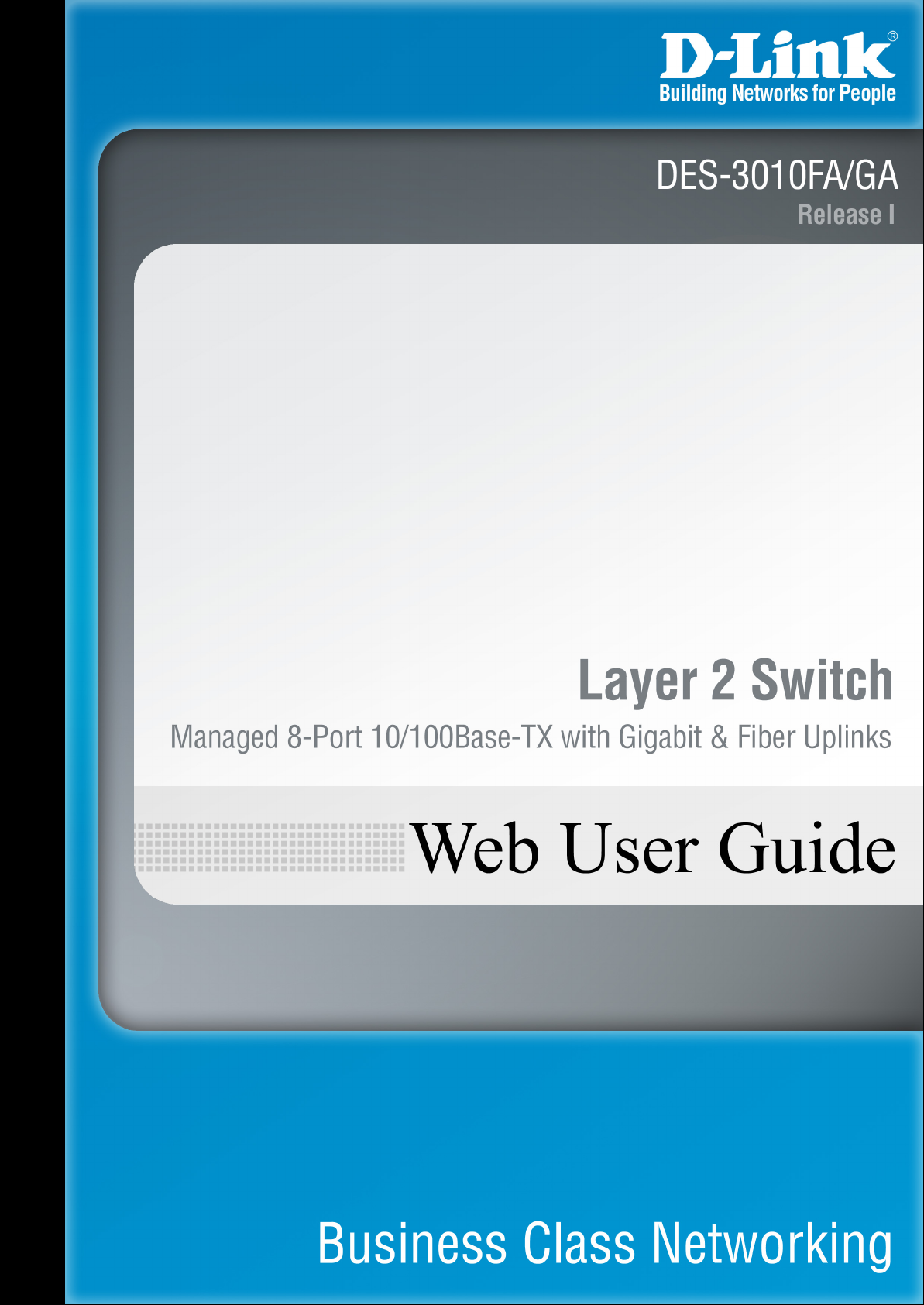
The following figure illustrates the DES-3010FA front panel.
Figure 1: DES-3010FA Front Panel
The device front panel is configured as follows:
• 8 Fast Ethernet ports — RJ-45 ports design ated as 10/100Base-TX . The RJ-45 ports are designated as
ports Ports1-8.
• DB-9 Console port — An asynchronous serial console port supporting the RS-232 electrical specification.
The port is used to connect the device to the console managing the device.
• 1000Base-T Copper port — Copper RJ-45 Gigabit port designated on the device as port 9.
• 100Base-FX port — Fiber port designated on the device as ports 10.
On the front panel there are the Port activity LEDs on each port and the Power LED displayed separately.
DES-3010GA Front Panel
The following figure illustrates the DES-3010GA front panel.
Page 11
Page 13
D-Link DES-3010FA/GA User Guide
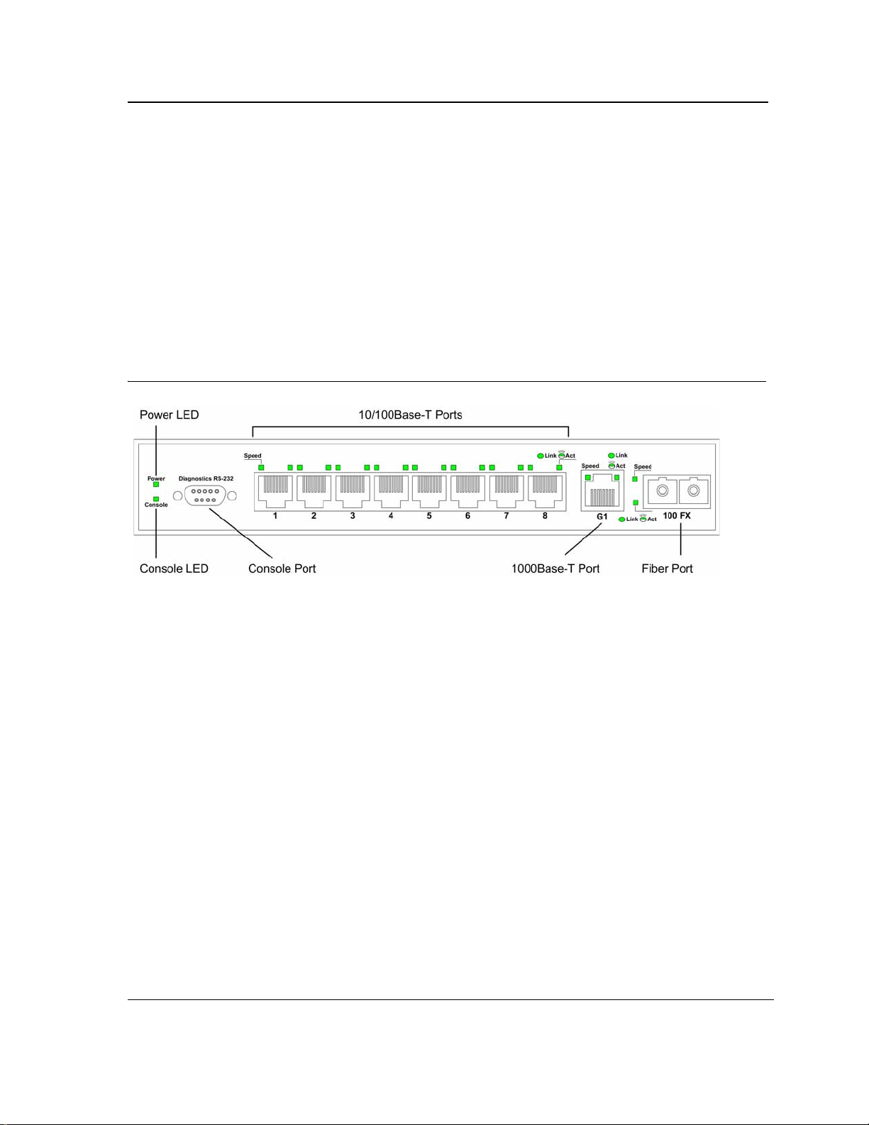
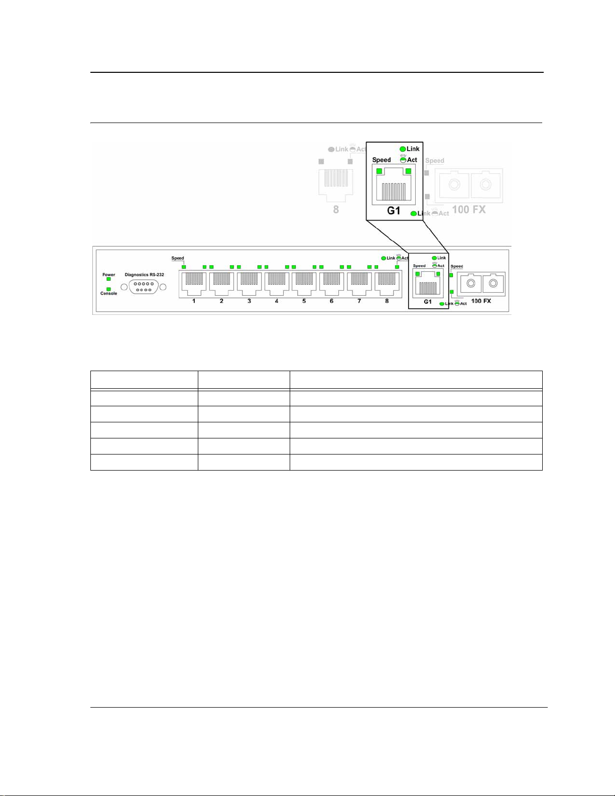
Figure 2: DES-3010GA Front Panel
The device front panel is configured as follows:
• 8 Fast Ethernet ports — RJ-45 ports designated as 10/100Base-TX . The RJ-45 ports are designated as
ports Ports1-8.
• DB-9 Console port — An asynchronous serial console port supporting the RS-232 electrical specification.
The port is used to connect the device to the console managing the device.
• 1000Base-T port — RJ-45 Gigabit port designated on the device as port 9.
• SFP Port — There is one SFP port, which contains 1000Base-X (fiber) connections.
On the front panel there are the Port activity LEDs on each port and the Power LED di splayed separately.
DES-3010 Back Panel
The following figure illustrates the DES-3010 back panel.
Figure 3: DES-3010 Back Panel
The DES-3010 device back panel contains a AC power supply interface.
Page 12
Page 14

Device Description
Ports Description
Ports Description
This section describes the device ports and includes the following topics:
• 10/100Base-TX Fast Ethernet Ports
• 1000Base-T Gigabit Ethernet Ports
• 100Base-FX Fiber port
• SFP Port
• DB-9 Console Port
10/100Base-TX Fast Ethernet Ports
The 10/100Base-TX Fast Ethernet ports are RJ-45.
1000Base-T Gigabit Ethernet Ports
The device contains a 1000 Base-TX Gigabit port. The port is an RJ-45 port which supports half- and full-duplex
mode 10/100/1000 Mbps.
100Base-FX Fiber Ports
The 100Base-FX Fast Ethernet port in the DES-3010FA device is a Fiber ports.
SFP Port
Small Form Factor Pluggable (SFP) Optical Transceivers are integrated duplex data GBIC links for bi-directional
communication over multimode optical fiber, designed for high-speed Fiber Channel data links. The SFP port is
designated as 1000Base-X.
The SFP (GBIC) port can be removed and inserted as required. The following figure illustrates the GBIC insertion.
Page 13
Page 15

D-Link DES-3010FA/GA User Guide
Figure 4: Inserting a GBIC into the Device
DB-9 Console Port
The DB-9 port is an asynchronous serial console port supporting the RS-232 electrical specification. The port is
used to connect the device to a console managing the device. This interface configuration is as follows:
• Eight data bits.
• One stop bit.
• No parity.
• Baud rate is 9600 (default). The user can change the rate from 115200 down to 9600 bps.
• Console speeds of 57600 and 115200.
Page 14
Page 16

Device Description
Cable Specifications
Cable Specifications
The following table contains the various cable specification for the DES-3010FA/GA:
Table 1: DES-3010FA/GA Cable Specifications
Cable Type Description
10Base-TX UTP Category 3, 4, 5 (100 meters max.)
EIA/TIA- 568 150-ohm STP (100 meters max.)
100Base-TX UTP Cat. 5 (100 meters max.)
EIA/TIA-568 150-ohm STP (100 meters max.)
1000Base-T UTP Cat. 5e (100 meters max.)
UTP Cat. 5 (100 meters max.)
EIA/TIA-568B 150-ohm STP (100 meters max.)
1000BASE-LX Single-mode fiber module (10km)
1000BASE-SX Multi-mode fiber module (550m)
1000BASE-LH Single-mode fiber module (40km)
1000BASE-ZX Single-mode fiber module (80km)
Mini-GBIC SFP Transceiver for 1000BASE-LX Single-mode fiber module (10km)
SFP Transceiver for 1000BASE-SX Multi-mode fiber module (550m)
SFP Transceiver for 1000BASE-LH Single-mode fiber module (40km)
SFP Transceiver for 1000BASE-ZX Single-mode fiber module (80km)
:
Table 2: DES-3010FA/GA Cable Lengths
Cable Type Description
DEM-310GT: SFP Transceiver for 1000BASE-LX, Single-mode fiber module
10km
DEM-311GT: SFP Transceiver for 1000BASE-SX, Multi-mode fiber module 550m
DEM-312GT2: SFP Transceiver for 1000BASE-SX+, Multi-mode module 2km
DEM-314GT: SFP Transceiver for 1000BASE-LH, Single-mode fiber module
50km
DEM-315GT: SFP Transceiver for 1000BASE-ZX, Single-mode fiber module
80km
1000Base-T Category 5e UTP CableCategory 5 UTP Cable(1000 Mbps) 100m
100Base-TX Category 5 UTP Cable (100 Mbps) 100m
10Base-TX Category 3 UTP Cable (10 Mbps) 100m
Page 15
Page 17
D-Link DES-3010FA/GA User Guide
LED Defiitions
The device front panels contain Light Emitting Diodes (LED) that indicate the device status.The different LED
types are as follows:
• Port LEDs — Indicate each port status.
• Power LED — Indicating the device power supply status.
Port LEDs
10/100Base-TX Fast Ethernet
The following figure illustrates the port LEDs.
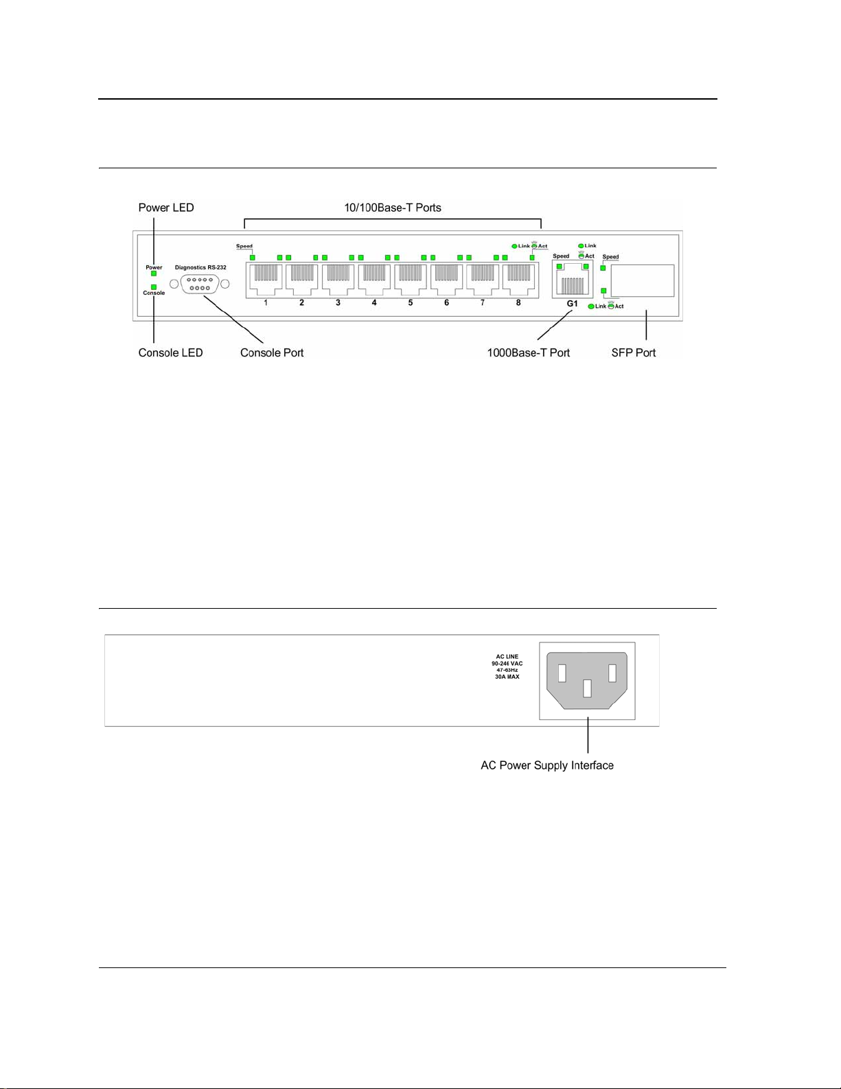
Figure 5: 10/100Base-TX Fast Ethernet RJ-45 Port LEDs
The RJ-45 ports have two LEDs, one for speed, and one for Link /activity. The LED indications are described in
the following table:
Table 3: 10/100Base-TX Fast Ethernet RJ-45 Port LED Indications
RJ-45 Port LEDs
Port Description LED Indication Description
Left LED - Speed Green A 100-Mbps link is established on the port.
Off
Link/Activity LED Green A link is established on the port.
Flashing Green There is data transmission on the port.
Off No link is established on the link.
A 10-Mbps link is established on the port or no link is established on the port.
1000Base-T Gigabit Ethernet RJ-45 Port LEDs
The following figure illustrates the port LEDs.
Page 16
Page 18
Device Description
LED Defiitions
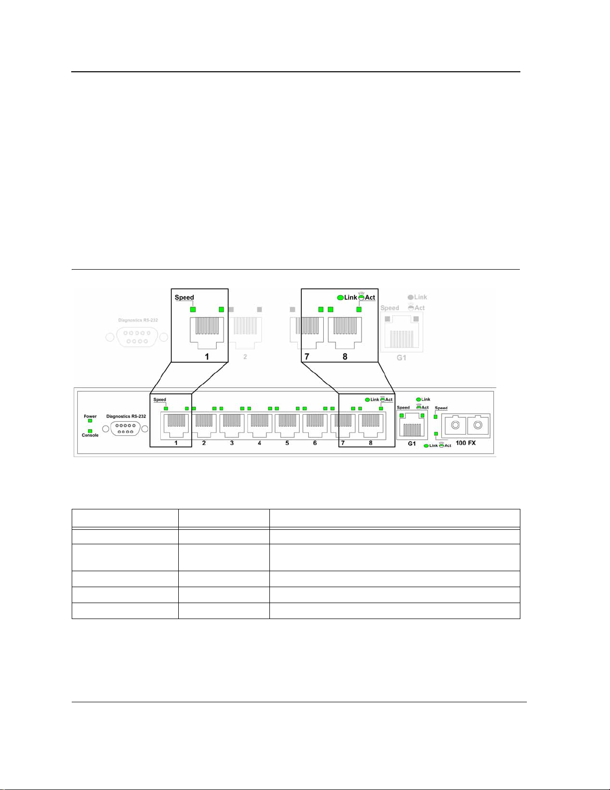
Figure 6: 1000Base-T Gigabit Ethernet RJ-45 Port LEDs
The RJ-45 ports have two LEDs, one for speed, and one for Link /activity. The LED indications are described in
the following table:
Table 4: 1000Base-T Gigabit Ethernet RJ-45 Port LED Indications
Port Description LED Indication Description
Left LED - Speed Green A 100/1000-Mbps link is established on the port.
Off No link is established on the port.
Link/Activity LED Green A link is established on the port.
Flashing Green There is data transmission on the port.
Off No link is established on the link.
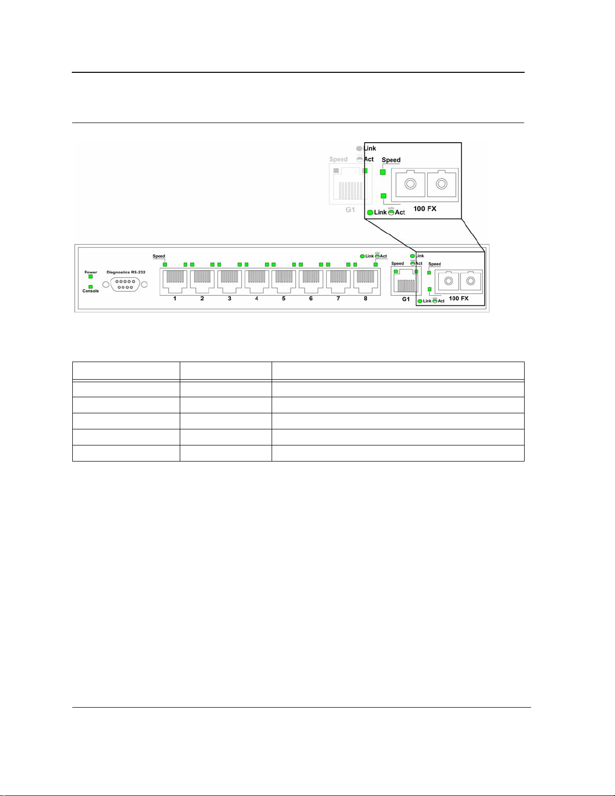
Fiber Port LEDs
The following figure illustrates the port LEDs.
Page 17
Page 19
D-Link DES-3010FA/GA User Guide
Figure 7: Fiber Port LEDs
The RJ-45 ports have two LEDs, one for speed, and one for Link /activity. The LED indications are described in
the following table:
Table 5: Fiber Port LED Indications
Port Description LED Indication Description
Left LED - Speed Green A 100/1000-Mbps link is established on the port.
Off No link is established on the port.
Link/Activity LED Green A link is established on the port.
Flashing Green There is data transmission on the port.
Off No link is established on the link.
Page 18
Page 20

SFP Port LEDs
The following figure illustrates the port LEDs.
Figure 8: SFP Port LEDs
Device Description
LED Defiitions
The RJ-45 ports have two LEDs, one for speed, and one for Link /Activity. The LED indications are described in
the following table:
Table 6: SFP Port LED Indications
Port Description LED Indication Description
Left LED - Speed Green A 100/1000-Mbps link is established on the port.
Off No link is established on the port.
Link/Activity LED Green A link is established on the port.
Flashing Green There is data transmission on the port.
Off No link is established on the link.
Power LED
The power supply status is indicated by the Power Supply LED on the front panel of the device.
The power supply port LED indications are described in the following table:
Table 7: Power Supply LED Indications
Port Description LED Indication Description
Power Off The system is not powered up. (power off)
Green Main power is functional (normal operation)
Console LED
The console status is indicated by the Console LED on the front panel of the device.
Page 19
Page 21
D-Link DES-3010FA/GA User Guide
The console LED indications are described in the following table:
Table 8: Console LED Indications
Port Description LED Indication Description
Console Flashing Green Power On Self Test (POST) is in progress.
Green
POST failure. A problem has been discovered during the
POST.
Cable, Port, and Pinout Information
This section describes the devices physical interfaces and provides information about cable connections. Stations
are connected to the device ports through the physical interface ports on the front panel. For each station, the
appropriate mode (Half/Full Duplex, Auto Negotiation) is set. The default is Auto Negotiation.
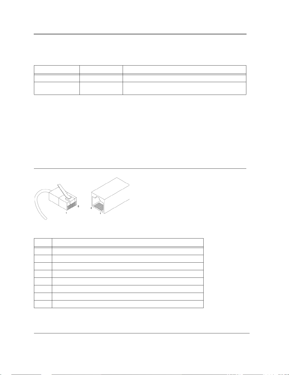
Pin Connections for the 10/100/1000 Ethernet Interface
The switching port can connect to stations wired in standard RJ-45 Ethernet station mode using straight cables.
Transmission devices connected to each other use crossed cables. The following figure illustrates the pin
allocation.
Figure 9: RJ-45 Pin Allocation
The following table describes the pin allocation
Table 9: RJ-45 Pin Connections for 10/100/1000 Base-TX
Pin Use
1
2
3
4
5
6
7
8 TxRx 4-
TxRx 1+
TxRx 1-
TxRx 2+
TxRx 2TxRx 3+
TxRx 3TxRx 4+
Page 20
Page 22

Physical Dimensions
The device has the following physical dimensions:
• Width: 220 mm (8.66 inch)
• Depth: 155mm (6.10 inch)
• Height: 35 mm (1.38 inch)
Device Description
Physical Dimensions
Page 21
Page 23

DLINK DES-3010FA/GA User Guide
Section 2. Mounting Device
This section contains information for installing the device, and includes the following sections:
• Preparing for Installation
• Installing the Device
• Connecting the Device
• Rack Installation
• Wall Installation
Page 22
Page 24

Mounting Device
Preparing for Installation
Preparing for Installation
This section provides an explanation for preparing the installation site, and includes the following topics:
• Installation Precautions
• Site Requirements
• Unpacking
Installation Precautions
Warnings
• The surface on which the switch is placed should be adequately secured to prevent it from becoming
unstable and/or falling over.
• Ensure the power source circuits are properly grounded.
• Observe and follow service markings. Do not service any product except as explained in your system
documentation. Opening or removing covers marked with a triangular symbol with a lighting bolt may
cause electrical shock. These components are to be serviced by trained service technicians only.
• Ensure the power cable, extension cable, and/or plug is not damaged.
• Ensure the product is not exposed to water.
• Ensure the device is not exposed to radiators and/or heat sources.
• Do not push foreign objects into the device, as it may cause a fire or electric shock.
• Use the device only with approved equipment.
• Allow the product to cool before removing covers or touching internal equipment.
• Ensure the switch does not overload the power circuits, wiring, and over-current protection. To determine the possibility of overloading the supply circuits, add together the ampere ratings of all devices
installed on the same circuit as the device being installed. Compare this total with the rating limit for
the circuit. The maximum ampere ratings are usually printed on the switch, near their AC power connectors.
Cautions
• Ensure the air flow around the front, sides, and back of the switch is not restricted.
• Ensure the cooling vents are not blocked.
• Do not install the switch in an environment where the operating ambient temperature might exceed
40ºC (104ºF).
Site Requirements
The device is placed on a table-top. Before installing the unit, verify that the location chosen for installation meets
the following site requirements.
• General — Ensure that the power supply is correctly installed.
• Power — The unit is installed within 1.5 m (5 feet) of a grounded, easily accessible outlet 100-250 VAC, 50-
60 Hz.
• Clearance — There is adequate frontal clearance for operator access. Allow clearance for cabling, power
connections and ventilation.
• Cabling — The cabling is routed to avoid sources of electrical noise such as radio transmitters, broadcast
amplifiers, power lines and fluorescent lighting fixtures.
Page 23
Page 25

DLINK DES-3010FA/GA User Guide
• Ambient Requirements — The ambient unit operating temperature range is 0 to 40ºC (32 to 104ºF) at a
relative humidity of up to 95%, non-condensing. Verify that water or moisture cannot enter the device casing.
Unpacking
This section contains information for unpacking the device, and includes the following topics:
• Package Contents
• Unpacking Essentials
Package Contents
While unpacking the device, ensure that the following items are included:
• The device
• Four rubber feet with adhesive backing
• Rack kit
• An AC power cable
• Console RS-232 cable with DB-9 connector
• Documentation CD
Unpacking Essentials
Note
Before unpacking the device, inspect the package and report any evidence of damage immediately.
To unpack the device perform the following:
1. It is recommended to put on an ESD wrist strap and attach the ESD clip to a metal surface to act as ground.
An ESD strap is not supplied with the device.
2. Place the container on a clean flat surface and cut all straps securing the container.
3. Open the container.
4. Carefully remove the device from the container and place it on a secure and clean surface.
5. Remove all packing material.
6. Inspect the product for damage. Report any damage immediately.
If any item is found missing or damaged, please contact your local D-Link reseller for replacement.
Page 24
Page 26
Mounting Device
Installing the Device
Installing the Device
The device can be installed on a flat surface or mounted in a rack. This section includes the following topics:
• Desktop or Shelf Installation
• Rack Installation
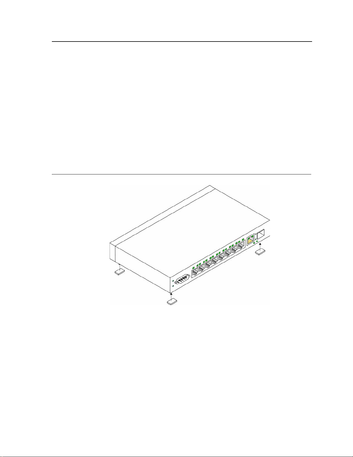
Desktop or Shelf Installation
When installing the switch on a desktop or shelf, the rubber feet included with the device should first be attached.
Attach these cushioning feet on the bottom at each corner of the device.
Ensure the surface is be able to support the weight of the device and the device cables.
To install the device on a surface, perform the follow ing:
1. Attach the rubber feet on the bottom of the device. The following figure illustrates the rubber feet installation
on the device.
Figure 10: Installing Rubber Feet
2. Set device down on a flat surface, while leaving 2 inches on each side and 5 inches at the back.
3. Ensure that the device has proper ventilation by allowing adequate space for ventilation between the device
and the objects around the device.
Rack Installation
The device can be mounted in an EIA standard-sized, 19-inch rack, which can be placed in a wiring closet with
other equipment. To install, the device the mounting brackets must first be attached on the devices’s sides.
Page 25
Page 27
DLINK DES-3010FA/GA User Guide
Notes
• Disconnect all cables from the unit before mounting the device in a rack or cabinet.
• When mounting multiple devices into a rack, mount the devices from the bottom up.
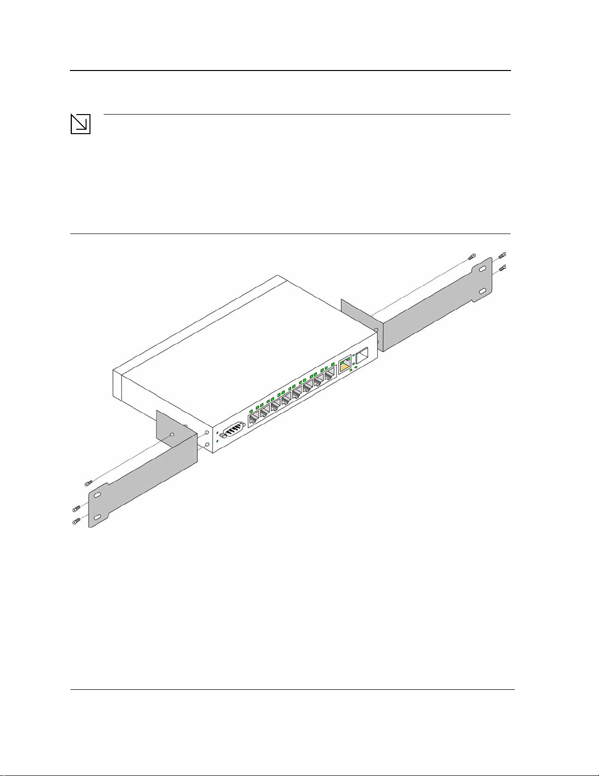
To install the device in a rack, perform the following:
1. Place the supplied rack-mounting bracket on one side of the device ensuring the mounting holes on the
device line up to the mounting holes on the rack mounting bracket. The following figure illustrates where to
mount the brackets.
Figure 11: Attaching the Mounting Brackets
2. Insert the supplied screws into the rack mounting holes and tighten with a screwdriver.
3. Repeat the process for the rack-mounting bracket on the other side of the device.
4. Insert the unit into the 19-inch rack ensuring the rack-mounting holes on the device line up to the mounting
hole on the rack. The following figure illustrates lining up and mounting the device in the rack.
Page 26
Page 28
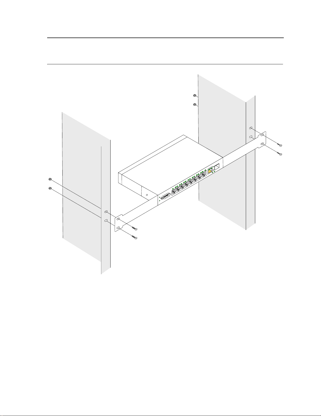
Figure 12: Mounting Device in a Rack
Mounting Device
Installing the Device
5. Secure the unit to the rack with the rack screws (not provided). Fasten the lower pair of screws before the
upper pair of screws. This ensures that the weight of the unit is evenly distributed during installation. Ensure
that the ventilation holes are not obstructed.
Page 27
Page 29

DLINK DES-3010FA/GA User Guide
Wall Installation
The device can also be mounted on a wall inside a wiring closet.
To mount the device on a wall, perform the following:
1. Mark two holes 100mm apart on the wa l l .
2. Drill holes into the wall where the marks have been made. The hole diameter and depth is defined by the wall
plug and screw combination being used to mount the device.
3. Insert the wall plugs unto the holes.
4. Screw the screws into the wall plugs allowing the heads to protrude from the wall. The device is mounted on
the protruded heads.
Figure 13: Inserting wall plugs and screws
Wall
Drilled Hole
Drilled Hole
5. Align the mounting holes on the back of the device with the screws in the wall, and mount the device on the
wall.
Page 28
Page 30
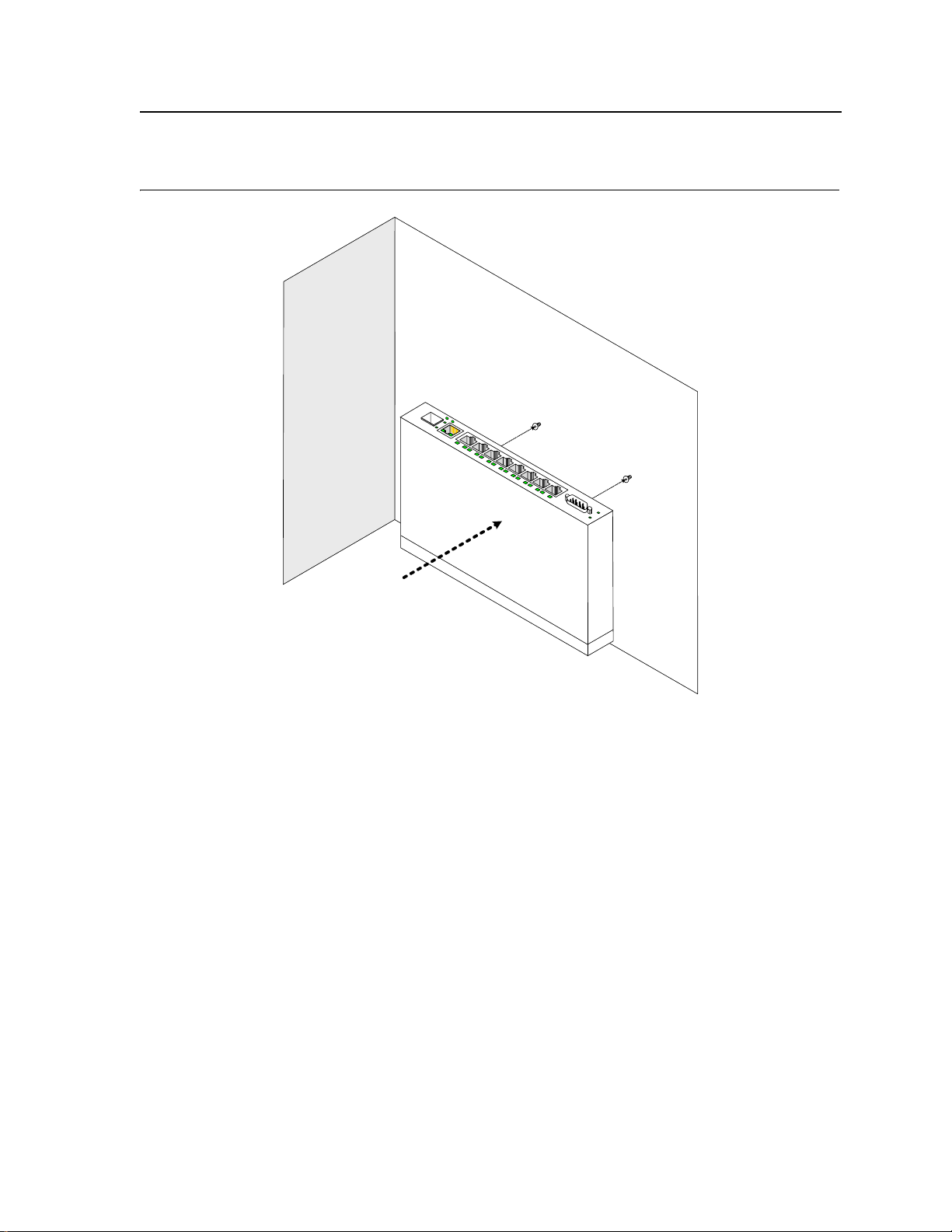
Figure 14: Mounting the device on the wall
Mounting Device
Connecting the Device
Wall
Connecting the Device
This section describes how to connect the device, and includes the following sections:
• Connecting the Switch to a Terminal
• AC Power Connection
Connecting the Switch to a Terminal
The device is connected to a terminal through an console port on the front panel, which enables a connection to a
terminal desktop system running terminal emulation software for monitoring and configuring the device.
The terminal must be a VT100 compatible terminal or a desktop or portable system with a serial port and running
VT100 terminal emulation software.
To connect a terminal to the device Console port, perform the following:
1. Connect a cable to the terminal running VT100 terminal emulation software.
2. Ensure that the terminal emulation software is set as follows:
a) Select the appropriate port to connect to the device.
b) Set the data rate to 9600 baud.
c) Set the data format to 8 data bits, 1 stop bit, and no parity.
Page 29
Page 31

DLINK DES-3010FA/GA User Guide
d) Set flow control to none.
e) Under Properties, select VT100 for Emulation mode.
f) Select Te rminal keys for Function, Arrow, and Ctrl keys. Ensure that the setting is for Terminal keys (not
Windows keys).
Note
When using HyperTerminal with Microsoft Windows 2000, ensure that you have Windows 2000 Service
Pack 2 or later installed. With Windows 2000 Service Pack 2, the arrow keys function properly in
HyperTerminal’s VT100 emulation. Go to www.microsoft.com for information on Windows 2000 service
packs.
3. Connect the cable to the console port on the device front panel.
AC Power Connection
To connect the power supply perform the following:
1. Using a 5-foot (1.5 m) standard power cable with safety ground connected, connect the power cable to the
AC main socket located on the back panel.
2. Connect the power cable to a grounded AC outlet.
3. Confirm that the device is connected and operating by checking that the Power Supply LED on the front panel
is green.
Page 30
Page 32

Starting and Configuring the Device
Section 3. Starting and Configuring the Device
This section describes initial device configuration and includes the following topics:
• Configuring the Terminal
• Installation Procedure
• Booting the Device
• Configuration Overview
• Advanced Configuration
• Startup Procedures
Page 31
Page 33

D-Link DES-3010FA/GA User Guide
Configuring the Terminal
After completing all external connections, connect a terminal to the device to monitor the boot and other
procedures.
To configure the device, the terminal must be running terminal emulation software.
Ensure that the terminal emulation software is configured as follows:
1. Connect the Chassis serial port to the switch module. The baud rate automatically boots up at 9600.
2. Set the data format to 8 data bits, 1 stop bit, and no parity.
3. Set Flow Control to none.
4. Under Properties, select VT100 for Emulation mode.
5. Select Terminal keys for Function, Arrow, and Ctrl keys. Ensure that the setting is for Terminal keys (not
Windows keys).
Note
When using HyperTerminal with Microsoft
Pack 2 or later is installed. With Windows 2000 Service Pack 2, the arrow keys function properly in
HyperTerminal’s VT100 emulation. Go to www.microsoft.com for information on Windows 2000 service
packs.
®
Windows 2000, make sure that Windows® 2000 Service
Installation Procedure
The order of installation and configuration procedures is illustrated in the following figu re. For the initial
configuration, the standard device configuration is performed.
Performing other functions is described later in this section.
Device Port Default Settings
The following table describes the device port default settings.
Table 10: Port Default Settin g
Function Default Settings
Port speed and mode 100M Auto-negotiation
Port forwarding state Enabled
Head of line blocking prevention On (Enabled)
Flow Control Off
Back Pressure Off
Note
These default settings can be modified once the device is installed.
Page 32
Page 34

Starting and Configuring the Device
Booting the Device
Booting the Device
The assumed bootup information is as follows:
• The device is delivered with a default configuration.
• The default user name is admin
• The default passwordis blank.
To login, perform the following steps:
1. Press Enter twice in rapid succession. The auto baud-rate process synchronizes the host and the device.
2. Enter the user name, admin. The default password is blank.
To boot the device, perform the following steps:
1. Ensure that the device port console is connected to a VT100 terminal device or VT100 terminal emulator.
2. Locate an AC power receptacle.
3. Deactivate the AC power receptacle.
4. Connect the device to the AC receptacle.
5. Activate the AC power receptacle.
The device goes through Power On Self Test (POST). POST runs every time the device is initialized and checks
hardware components to determine if the device is fully operational before completely booting. If a critical problem
is detected, the program flow stops. If POST passes successfully, a valid executable image is loaded into RAM.
POST messages are displayed on the terminal and indicate test success or failure.
As the device boots, the bootup test first counts the device memory availability and then continues to boot. The
following screen is an example of the displayed POST:
------ Performing the Power-On Self Test (POST) ------
UART Channel Loopback Test........................PASS
Testing the System SDRAM..........................PASS
Boot1 Checksum Test...............................PASS
Boot2 Checksum Test...............................PASS
Flash Image Validation Test.......................PASS
FRU Validation Test...............................PASS
BOOT Software Version x.x.x.xx Built 22-Jan-2005 15:09:28
Processor: xxxxxx xxxxx , xxx MByte SDRAM.
I-Cache x KB. D-Cache x KB. Cache Enabled.
Autoboot in 2 seconds - press RETURN or Esc. to abort and enter prom.
Preparing to decompress...
The boot process runs for approximately 60 seconds.
The auto-boot message displayed at the end of POST (see the last lines) indicates that no problems were
encountered during boot.
During boot, the Startup menu can be used to run special procedures. To enter the Startup menu, press <Esc> or
<Enter> within the first two seconds after the auto-boot message is displ ayed.
Page 33
Page 35

D-Link DES-3010FA/GA User Guide
If the system boot process is not interrupted by pressing <Esc> or <Enter>, the process continues
decompressing and loading the code into RAM. The code starts running from RAM and the list of numbered
system ports.
After the device boots successfully, a system prompt is displayed (console>) which is used to configure the
device. However , before configuring the device, ensure that the latest software version is installed on the device. If
it is not the latest version, download and install the latest version. For more information on downloading the latest
version, see Software Download and Reboot.
Configuration Overview
Before assigning a static IP address to the device, obtain the following information:
• A specific IP address that has been allocated to the device in order for it to be configured.
• A default route.
• A network mask for the network.
There are two configuration types:
• Initial Configuration — Consists of configuration functions with basic security considerations.
• Advanced Configuration — Consists of dynamic IP configuration and more advanced security considerations.
Note
After making any configuration changes, the new configuration must be saved before rebooting. To save
the configuration, enter:
console# copy running-config startup-config
Initial Configuration
Initial configuration, which starts after the device has booted successfully, includes static IP address and subnet
mask configuration, and setting user names and privilege levels to allow remote management. If the device is to
be managed from an SNMP-based management station, SNMP community strings must also be configured.
The following configurations are completed, and the initial configuration uses the following assumptions:
• The device was never configured before, and is in the same state as when it was received.
• The device booted successfully.
• The Serial connection is established and the console prompt is displayed on the screen of a VT100 terminal
device. (Press <Enter> several times to verify that the prompt displays correctly.)
• The device is not configured with a default user name and password.
The initial device configuration is through the Serial port. After the initial configuration, the device can then be
managed either from the already connected Serial port or remotely through an interface defined during the initial
configuration.
During the initial configuration, you can:
• Configure a user name, a pass wo rd, and the highest privilege level of 15.
• Configure the static IP address and the default gateway.
• Configure the SNMP read/write community string.
• Assign the IP address allocated by the DHCP server.
Before applying the initial configuration procedure to the device, the following information must be obtained from
the network administrator:
• The IP address to be assigned to a VLAN through which the device is managed.
• The IP subnet mask for the network.
Page 34
Page 36

Starting and Configuring the Device
Configuration Overview
• The default gateway IP address.
• The SNMP community .
Static IP Address and Subnet Mask
IP interfaces can be configured on each port of the device. After entering the configuration command, it is
recommended to check if a port was configured with the IP address by entering the
command.
Note
The commands to configure the device are port specific.
To manage the switch from a remote network, a static route must be configured, which is an IP address to where
packets are sent when no entries are found in the device tables. The configured IP address must belong to the
same subnet as one of the device IP interfaces.
To configure a static route, enter the command at the system prompt, as shown in the following configuration
example, where 100.1.1.1 is the specific management station, the IP address is defined on VLAN 1, and the
default gateway is defined as 100.1.1.10. Note that by default, all ports are members of VLAN 1, which is the
default VLAN.
console# configure
console(config)# interface vlan 1
console(config-if)# ip address 100.1.1.1 255.255.255.0
console(config-if)# exit
console# default-gateway 100.1.1.10 255.255.255.0
Confirm that the IP address has been correctly configured as follows:
console# show ip interface
Proxy ARP is disabled
IP Address I/F Type
----------- -------- -----------
100.1.1.1/24 vlan 1 static
show ip interface
Assigning Static IP Addresses on a Default VLAN
This example uses the following assumptions:
• The IP address to be assigned to the VLAN interface is 100.1.1.110
• The IP subnet mask for the network is 255.255.255.0
• The IP address of the default route is 192.168.1.1
• The read/write SNMP community string is "private"
console>
console#
console(config)#
console(config)#
console (config-if) #
console (config-if) #
enable
configure
username admin password
interface
VLAN 1
ip address
exit
dlink
100.1.1.110
Page 35
level
15
Page 37

D-Link DES-3010FA/GA User Guide
console (config) #
console (config) #
console(config)# exit
console#
ip default-gateway
snmp-server community private
100.1.1.110
rw
Verifying the IP and Default Gateway Addresses
To ensure that the IP address and the default gateway were properly assigned, execute the following command
and examine its output:
console # - ip interface
Gateway IP Address Activity status
--------------------- ---------------
192.168.1.1 Active
IP address Interface Type
-------------- ----------- ------
192.168.1.123/24 VLAN 1 Static
User Name
A user name is used to manage the device remotely, for example through SSH, Telnet, or the Web interface. To
gain complete administrative (super-user) control over the device, the highest privilege (15) must be specified.
Note
Only the administrator (super-user) with the highest privilege level (15) is allowed to manage the device
through the web browser interface.
For more information about the privilege level, see the CLI Reference Guide.
The configured user name is entered as a login name for remote management sessions. To configure a user
name, password, and privilege level, enter the command at the system prompt as shown in the configuration
example:
console> enable
console# configure
console(config)# username admin password lee privilege 15
SNMP Community Strings
Simple Network Management Protocol (SNMP) provides a method for managing network devices. Devices
supporting SNMP run a local software agent. The SNMP agents maintain a list of variables, used to manage the
device. The variables are defined in the Management Information Base (MIB). The SNMP agent defines the MIB
specification format, as well as the format used to access the information over the network.
Access rights to the SNMP agents are controlled by access strings and SNMP community strings.
The device is SNMP-compliant, and contains an SNMP agent that supports a set of standard and private MIB
variables. Developers of management stations require the exact structure of the MIB tree and receive the
complete private MIBs information before being able to manage the MIBs.
All parameters are manageable from any SNMP management platform, except the SNMP management station IP
address and community (community name and access rights). The SNMP management access to the switch is
disabled if no community strings exist.
Page 36
Page 38

Starting and Configuring the Device
Configuration Overview
Note
The device is delivered with no community strings configured.
The community-string, community-access, and IP address can be configured through the local terminal during the
initial configuration procedure.
The SNMP configuration options are:
• Community string
– Access rights options: ro (read only), rw (read-and-write), and su (super).
– An option to configure IP address or not. If an IP address is not configured, it means that all community
members having the same community name are granted the same access rights.
Common practice is to use two community strings for the device, one (public community) with read-only access
and the other (private community) with read-write access. The public string allows authorized management
stations to retrieve MIB objects, while the private string allows authorized management stations to retrieve and
modify MIB objects.
During initial configuration, it is recommended to configure the device according to the network administrator
requirements, in accordance with using an SNMP-based management station. During the initial configuration
procedure, the community-string, community-access, and IP address can be set through the local terminal.
The SNMP configuration options are:
• Community string.
– Read Only — Community members can view configuration information, but cannot change any
information.
– Read/Write — Community members can view and modify configuration information.
– Super — Community members have administration access.
• Configurable IP address. If an IP address is not configured, all community members with the same
community name are granted the same access rights.
To configure an SNMP station IP address and community string(s), perform the following steps:
1. At the console prompt, enter the command Enable. The prompt is displayed as #.
2. Enter the command configure and press <Enter>.
3. In configuration mode, enter the SNMP configuration command with the parameters including community
name (private), community access right (read and write), and IP address, as shown in the following example:
console#
config(config)# snmp-server community private rw 11.1.1.2 type router
config(config)# exit
console(config)# show snmp
Community-String Community-Access IP address
------------------------ --------------------------- -------------------private readWrite 11.1.1.2
Traps are enabled.
Authentication-failure trap is enabled.
configure
Trap-Rec-Address Trap-Rec-Community Version
------------------------ --------------------------- -------------------System
Page 37
Page 39

D-Link DES-3010FA/GA User Guide
Contact:
System Location:
This completes the initial configuration of the device from a local terminal. The configured parameters enable
further device configuration from any remote location.
Page 38
Page 40

Starting and Configuring the Device
Advanced Configuration
Advanced Configuration
This section provides information about dynamic allocation of IP addresses and security management based on
the authentication, authorization, and accounting (AAA) mechanism, and includes the following topics:
• Receiving an IP Address from a DHCP Server
• Receiving an IP Address from a BOOTP Server
• Security Management and Password Configuration
When configuring or receiving IP addresses through DHCP and BOOTP, the configuration received from these
servers includes the IP address, and may include a subnet mask and default gateway.
Receiving an IP Address from a DHCP Server
When using the DHCP protocol to retrieve an IP address, the device acts as a DHCP client. To receive an IP
address from a DHCP server, perform the following steps:
1. Select and connect any port to a DHCP server or to a subnet that has a DHCP server on it, in order to retrieve
the IP address.
2. Enter the following commands to use the selected port for receiving the IP address. In the following example,
the commands are based on the port type used for configuration.
console# configure
console(config)# interface ethernet 1
console(config-if)# ip address dhcp hostname admin-host
console(config-if)# exit
console(config)#
3. To verify the IP address, enter the show ip interface command at the system prompt as shown in the
following example.
console#
IP Address I/F Type
--------------- ---------- ---------
100.1.1.1/24 vlan 1 dynamic
show ip interface
Notes
• The device configuration does not have to be deleted to retrieve an IP address for the DHCP server.
• When copying configuration files, avoid using a configuration file that contains an instruction to
enable DHCP on an interface that connects to the same DHCP server, or to one with an identical configuration. As a result of the copying configuration, the switch retrieves the new configuration file and
boots from it. The device then enables DHCP as instructed in the new configuration file, and the
DHCP instructs it to reload the same file.
Receiving an IP Address from a BOOTP Server
The standard BOOTP protocol is supported and enables the switch to automatically download its IP host
configuration from any standard BOOTP server in the network. In this case, the device acts as a BOOTP client.
To receive an IP address from a BOOTP server:
1. Select and connect any port to a BOOTP server or subnet containing such a server.
2. At the system prompt, enter the delete startup configuration command to delete the startup configuration
from flash.
Page 39
Page 41

D-Link DES-3010FA/GA User Guide
The device reboots with no configuration and in 60 seconds starts sending BOOTP requests. The device
receives the IP address automatically.
Note
When the device reboot begins, any input at the ASCII terminal or keyboard automatically cancels the
BOOTP process before completion, and the device does not receive an IP address from the BOOTP
server.
The following example illustrates the process:
console# enable
console# delete startup-config
Startup file was deleted
console# reload
You haven’t saved your changes. Are you sure you want to continue (y/n)[n]?
This command will reset the whole system and disconnect your current session.Do you want
to continue (y/n)[n]?
******************************************************
/*the device reboots */
3. To verify the IP address, enter the show ip interface command. The device is now configured with an IP
address.
Security Management and Password Configuration
System security is handled through the AAA (Authentication, Authorization, and Accounting) mechanism that
manages user access rights, privileges, and management methods. AAA uses both local and remote user
databases. Data encryption is handled through the SSH mechanism.
The system is delivered with the user name admin, and no default password configured; all user names and
passwords are user-defined. If a user-defined user name and/or password is lost, a password recovery procedure
can be initiated from the Startup menu. The procedure is applicable for the local terminal only and allows a onetime access to the device from the local terminal with no password entered.
The security passwords can be configured for the following services:
• Console
• Telnet
• SSH
• HTTP
• HTTPS
Note
When creating a user name, the default priority is 1, which allows access but not configura ti on rights. A
priority of 15 must be set to enable full access and configuration rights to the device. Although user names
can be assigned privilege level 15 without a password, it is recommended to always assign a password.
If there is no specified password, privileged users can access the web interface with any password.
Page 40
Page 42

Starting and Configuring the Device
Advanced Configuration
This section contains the following topics:
• Configuring an Initial Console Password
• Configuring an Initial T elnet Password
• Configuring an Initial SSH password
• Configuring an Initial HTTP Password
• Configuring an initial HTTPS Password
Configuring an Initial Console Password
To configure an initial console password, enter the following commands:
console(config)# aaa authentication login default line
console(config)# aaa authentication enable default line
console(config)# line console
console(config-line)# login authentication default
console(config-line)# enable authentication default
console(config-line)# password george
When initially logging on to a device through a console session, ente r george at the password prompt.
When changing a device mode to enable, enter george at the password prompt.
Configuring an Initial Telnet Password
To configure an initial Telnet password, en ter the following commands:
console(config)# aaa authentication login default line
console(config)# aaa authentication enable default line
console(config)# line telnet
console(config-line)# login authentication default
console(config-line)# enable authentication default
console(config-line)# password bob
When initially logging onto a device through a Telnet session, enter bob at the password prompt.
When changing a device mode to enable, enter bob.
Configuring an Initial SSH password
To configure an initial SSH password, enter the following commands:
console(config)# aaa authentication login default line
console(config)# aaa authentication enable default line
console(config)# line ssh
console(config-line)# login authentication default
console(config-line)# enable authentication default
console(config-line)# password jones
When initially logging onto a device through a SSH session, enter jones at the password prompt.
When changing a device mode to enable, enter jones.
Configuring an Initial HTTP Password
To configure an initial HTTP password, enter the following commands:
Page 41
Page 43

D-Link DES-3010FA/GA User Guide
console(config)# ip http authentication local
console(config)# username admin password user1 level 15
Configuring an initial HTTPS Password
To configure an initial HTTPS password, enter the following commands:
console(config)# ip https authentication local
console(config)# username admin password user1 level 15
Enter the following commands when configuring to use a console, a Telnet, or an SSH session to use an HTTPS
session.
In the Web browser, enable SSL 2.0 or greater for the content of the page to appear.
console(config)# crypto certificate generate key_generate
console(config)# ip https server
When initially enabling an http or https session, enter admin for user name and user1 for password.
Note
HTTP and HTTPS services require level 15 access and connect directly to the configuration level access.
Page 42
Page 44

Starting and Configuring the Device
Startup Procedures
Startup Procedures
This section includes the following topics:
• Startup Menu Procedures
• Software Download and Reboot
Startup Menu Procedures
The procedures called from the Startup menu cover software download, flash handling, and password recovery.
The diagnostics procedures are for use by technical support personnel only and are not disclosed in this
document.
The Startup menu can be entered when booting the device. A user input must be entered immediately after the
POST test.
To enter the Startup menu:
1. Turn the power on and watch for the auto-boot message.
This command will reset the whole system and disconnect your current
session. Do you want to continue (y/n) [n] ?
y
**************************************************
***************** SYSTEM RESET *****************
**************************************************
------ Performing the Power-On Self Test (POST) ------
UART Channel Loopback Test............PASS
Testing the System SDRAM.............PASS
I2C Bus Test.........................PASS
Boot1 Checksum Test................PASS
Boot2 Checksum Test................PASS
Flash Image Validation Test............PASS
BOOT Software Version 1.0.0.11 Built 10-Apr-2005 13:25:46
DES3010 D-LINK board - based on Samsung S3C2510A ARM940T processor.
32 MByte SDRAM. I-Cache 4 KB. D-Cache 4 KB. Cache Enabled
Autoboot in 2 seconds - press RETURN or Esc. to abort and enter prom.
2. When the auto-boot message appears, press <Enter> to display the Startup menu. The Startup menu
procedures can be done using the ASCII terminal or Windows HyperTerminal.
[1] Download Software
[2] Erase Flash File
[3] Erase Flash Sectors
[4] Password Recovery Procedure
[5] Enter Diagnostic Mode
[6] Back
Enter your choice or press 'ESC' to exit:Enter your choice or press 'ESC' to exit:
The following sections describe the available Startup menu options.
Page 43
.
Page 45

D-Link DES-3010FA/GA User Guide
Note
When selecting an option from the Startup menu, time must be taken into account. If no selection is made
within 35 seconds (default), the device times out. This default value can be changed through the CLI.
Only technical support personnel can use Diagnostics Mode. For this reason, Diagnostics Mode is not described
in this guide.
Software Download and Reboot
This section describes the procedures for downloading software and rebooting the system, and includes the
following topics:
• Software Download from the Startup Menu
• Erasing the Flash File
• Password Recovery
• Software Download through TFTP Server
• Software Download through XModem
Software Download from the Startup Menu
The software download procedure is performed when a new version must be downloaded to replace corrupted
files, or when the system software must be upgraded. To download software from the Startup menu:
1. From the Startup menu, press [1]. The following prompt appears:
Downloading code using XMODEM
2. When using HyperTerminal, click Transfer on the HyperTerminal Menu Bar.
3. In the Filename field, enter the file path for the file to be downloaded.
4. Ensure that the Xmodem protocol is selected in the Protocol field.
5. Press Send. The software is downloaded.
Note
After software download, the device reboots automatically.
Erasing the Flash File
In some cases, the device configuration must be erased. If the configuration is erased, all parameters configured
via CLI, EWS, or SNMP must be reconfigured.
To erase the device configuration:
1. From the Startup menu, press
displayed:
Warning! About to erase a Flash file.
Are you sure (Y/N)? y
2. Press Y. The following message is displayed.
Write Flash file name (Up to 8 characters, Enter for none.):config
File config (if present) will be erased after system initialization
======== Press Enter To Continue ========
3. Enter config as the name of the flash file. The configuration is erased and the device reboots.
[2] within two seconds to erase the flash file. The foll ow i n g message is
Page 44
Page 46

Starting and Configuring the Device
Startup Procedures
4. Repeat the initial device configuration.
Password Recovery
If a password is lost, you can perform the password recovery procedure from the Startup menu. The password
recovery procedure enables
To recover a lost password for the local terminal only:
1. From the Startup menu, type [4] and press <Enter>. The password is deleted.
Note
To ensure device security, reconfigure passwords for applicable manag ement methods.
entry to
the device one time without a password.
Software Download through TFTP Server
This section contains instructions for downloading device software (system and boot images) through a TFTP
server. The TFTP server must be configured before beginning to download the software. This section contains the
following topics:
• System Image Download
• Boot Image Download
System Image Download
The device boots and runs when decompressing the system image from the flash memory area where a copy of
the system image is stored. When a new image is downloaded, it is saved in the area allocated for the other
system image copy.
On the next boot, the device decompresses and runs the currently active system image unless otherwise directed.
To download a system image through the TFTP server:
1. Ensure that an IP address is configured on one of the device ports and pings can be sent to the TFTP server.
2. Make sure that the file to be downloaded is saved on the TFTP server (the arc file).
3. Enter show version to verify which software version is currently running on the device. The following is an
example of the information that appears:
console# show version
SW version 1.0.0.42 (date 22-Jul-2004 time 13:42:41)
Boot version 1.0.0.18 (date 01-Jun-2004 time 15:12:20)
HW version
4. Enter show bootvar to verify which system image is currently active. The following is an example of the
information that appears:
console# sh bootvar
Images currently available on the Flash
Image-1 active (selected for next boot)
Image-2 not active
console#
5. Enter copy tftp://{tftp address}/{file name} image to copy a new system image to the
device. When the new image is downloaded, it is saved in the area allocated for the other copy of system
image (image-2, as given in the example). The following is an example of the information that appears:
console# copy tftp://176.215.31.3/file1.ros image
Page 45
Page 47

D-Link DES-3010FA/GA User Guide
!!!!!!!!!!!!!!!!!!!!!!!!!!!!!!!!!!!!!!!!!!!!!!!!!!!!!!!!!!!!!!!!!!!!!!!!!!!!!!!!!!!!!!!!!
!!!!!!!!!!!!!!!!!!!!!!!!!!!!!!!!!!!!!!!!!!!
Copy took 00:01:11 [hh:mm:ss]
Exclamation points indicate that a copying process is in progress. Each symbol (!) corresponds to 512 bytes
transferred successfully. A period indicates that the copying process timed out. Many periods in a row indicate
that the copying process failed.
6. Enter the reload command. The following message is displayed:
console# reload
This command will reset the whole system and disconnect your current
session. Do you want to continue (y/n) [n]?
7. Enter y. The device reboots.
Boot Image Download
Loading a new boot image from the TFTP server and programming it into the flash updates the boot image. The
boot image is loaded when the device is powered on. A user has no control over the boot image copies.
To download a boot image through the TFTP server:
1. Ensure that an IP address is configured on one of the device ports and pings can be sent to the TFTP server.
2. Ensure that the file to be downloaded is saved on the TFTP server (the
3. Enter
4. Enter copy tftp://{tftp address}/{file name} boot to copy the boot image to the device.
5. Enter the reload command. The following message is displayed:
6. Enter y. The device reboots.
show version to verify which software version is currently running on the device. The following is an
example of the information that appears:
console# sh ver
SW version 1.0.0.42 (date 22-Jul-2005 time 13:42:41)
Boot version 1.0.0.18 (date 01-Jun-2005 time 15:12:20)
HW version 00.00.01 (date 01-May-2005 time 12:12:20)
The following is an example of the information that appears:
console# boot copy tftp://176.215.31.3/332448-10018.rfb boot
!!!!!!!!!!!!!!!!!!!!!!!!!!!!!!!!!!!!!!!!!!!!!!!!!!!!!!!!!!!!!!!!!!!!!!!!!!!!!!!!!!!!!!!!!
!!!!!!!!!!!!!!!!!!!!!!!!!!!!!!!!!!!!!!!!!!!
Copy: 2739187 bytes copied in 00:01:13 [hh:mm:ss]
console# reload
This command will reset the whole system and disconnect your current
session. Do you want to continue (y/n) [n]?
rfb file).
Software Download through XModem
This section contains instructions for downloading device software (system and boot images) using XModem,
which is a data transfer protocol for updating backup configuration files.
To download a boot file using XModem:
1. Enter the command
The device is ready to receive the file via the XModem protocol and displays text similar to the following:
console#
copy
xmodem: boot.
xmodem:boot
Page 46
Page 48

Please download program using XMODEM.
console#
2. Specify the path of the source file within 20 seconds.
If the path is not specified within 20 seconds, the command times out.
To download a software image file using XModem:
1. Enter the command
The switch is ready to receive the file via the XMo dem protocol.
2. Specify the path of the source file to begin the transfer process.
The following is an example of the information that appears:
console#
Please download program using XMODEM
copy
console# xmodem:image
xmodem: image
.
Starting and Configuring the Device
Startup Procedures
Page 47
Page 49

D-Link DES-3010FA/GA User Guide
D-Link DES 3010FA/GA EWS User Guide
Page 48
Page 50

Section 4. Getting Started
This section provides an introduction to the user interface, and includes the following topics:
• Starting the D-Link Embedded Web Interface
• Understanding the D-Link Embedded Web Interface
• Using Screen and Table Options
• Resetting the Device
• Logging off from the Device
Getting Started
Page 49
Page 51

D-Link DES-3010FA/GA User Guide
Starting the D-Link Embedded Web Interface
This section contains information on starting the D-Link Embedded Web interface. To access the D-Link user
interface:
1. Open an Internet browser.
2. Ensure that pop-up blockers are disabled. If pop-up blockers are enable, edit, add, and device information
messages may not open.
3. Enter the device IP address in the address bar and press <Enter>. The Enter Network Password Page
opens:
Figure 15: Enter Network Password Page
4. Enter your user name and password.
Notes
• The device is configured with a user name that is admin and a password that is blank, and can be
configured without entering a password.
• Passwords are case sensitive.
• To operate the device, disable all pop-ups with a popup blocker.
5. Click . The D-Link Embedded Web Interface Home Page opens:
Page 50
Page 52

Understanding the D-Link Embedded Web Interface
Figure 16: D-Link Embedded Web Interface Home Page
Getting Started
Understanding the D-Link Embedded Web Interface
The D-Link Embedded Web Interface Home Page contains the following views:
• Port LED Indicators — Located at the top of the home page, the port LED indicators provide a visual repre-
sentation of the ports on the D-Link front panel.
• Tab Area — Located under the LED indicators, the tab area contains a list of the device features and their
components.
• Device View — Located in the main part of the home page, the device view provides a view of the device, an
information or table area, and configuration instructions.
Page 51
Page 53

D-Link DES-3010FA/GA User Guide
Figure 17: D-Link Embedded Web Interface Components
The following table lists the user interface components with their corresponding numbers:
Table 11: Interface Components
View Desc ript ion
1 Tree View Tree View provides easy navigation through the configurable device features.
The main branches expand to display the sub-features.
2 Device View
3 Tab Area The Tab Area enables navigation through the different device features. Click
4 Zoom View Provides a graphic of the device on which D-Lin k Web Interface runs.
5 D-Link Web Interface Infor-
mation Tabs
This section provides the following additional information:
Device View provides information about device ports, current configuration
and status, table information, and feature components. Device View also
displays other device information and dialog boxes for configuring parameters.
the tabs to view all the components under a specific feature.
Provide access to online help, and contain information about the EWS.
• Device Representation — Provides an explanation of the D-Link user interface buttons, including both man-
agement buttons and task icons.
• Using the D-Link Embedded Web Interface Management Buttons — Provides instructions for adding,
modifying, and deleting configuration parameters.
Page 52
Page 54

Getting Started
Understanding the D-Link Embedded Web Interface
Device Representation
The D-Link Embedded Web Interface Home Page contains a graphical panel representation of the device.
Figure 18: Device Representation
Using the D-Link Embedded Web Interface Management Buttons
Configuration Management buttons and icons provide an easy method of configuring device information, and
include the following:
T able 12: D-Link Web Interface Configuration Buttons
Button Button Name Description
Clear Logs Clears system logs.
Create
Edit Modifies configuration settings.
Submit
Test Performs cable tests.
Query Queries the device table.
T able 13: D-Link Web Interface Information Tabs
Tab Tab Name Description
Help Opens the online help.
Logout Opens the Logout page.
Enables creation of configuration
entries.
Saves configuration changes to the
device.
Page 53
Page 55

D-Link DES-3010FA/GA User Guide
Using Screen and Table Options
D-Link contains screens and tables for configuring devices. This section contains the following topics:
• Adding Configuration Information
• Modifying Configuration Information
• Deleting Configuration Information
Adding Configuration Information
User-defined information can be added to specific D-Link Web Interface pages, by opening a new Add page. To
add information to tables or D-Link Web Interface pages:
1. Open an D-Link Web Interface page.
2. Click . An add page opens, such as the Add SNTP Interface Page:
Figure 19: Add SNTP Interface
3. Define the fields.
4. Click . The configuration information is saved, and the device is updated.
Modifying Configuration Information
1. Open The D-Link Embedded Web Interface page.
2. Select a table entry.
3. Click . A modification page, such as the IP Interface Settings Page op ens:
Page 54
Page 56

Using Screen and Table Options
Figure 20: IP Interface Settings Page
4. Modify the fields as required.
5. Click . The fields are modified, and the information is saved to the device.
Getting Started
Deleting Configuration Information
1. Open The D-Link Embedded Web Interface page.
2. Select a table row.
3. Select the Remove checkbox.
4. Click . The information is deleted, and the device is updated.
Page 55
Page 57

D-Link DES-3010FA/GA User Guide
Resetting the Device
The Reset page enables the device to be reset from a remote location.
Note
To prevent the current configuration from being lost, save all changes from the running configuration file
to the startup configuration file before resetting the device. For instructions, see “Copying Fi les” on
page 199.
To reset the device:
1. Click System > General > Reset. The Reset page opens.
Figure 21: Reset Page
2. Click . A confirmation message is displayed.
Page 56
Page 58

Getting Started
Resetting the Device
Figure 22: Reset Confirmation Message
3. Click . The device is reset, and a prompt for a user name and password is displayed.
4. Enter a user name and password to reconnect to the web Interface.
Page 57
Page 59

D-Link DES-3010FA/GA User Guide
Logging off from the Device
1. Click . The Logout Page opens.
Figure 23: Logout Page
2. Click . The D-Link Embedded Web Interface Home Page closes.
Page 58
Page 60

Managing Device Information
Section 5. Managing Device Information
The System Information Page contains parameters for configuring general device information, including the system name, location, and contact, the system MAC Address, System Object ID, System Up Time, System IP and
MAC addresses, and both software and hardware versions. To define the general system information:
1. Click System > General > Description. The System Information Page opens:
Figure 24: System Information Page
The System Information Page contains the following fields:
• Model Name — Displays the device model number and name.
• System Name — Defines the user-defined device name. The field range is 0-160 characters.
• System Location — Defines the location where the system is currently running. The field range is 0-160
characters.
• System Contact — Defines the name of the contact person. The field range is 0-160 characters.
• System Object ID — Displays the vendor’s authoritative identification of the network management sub-
system contained in the entity.
• System Up Time — Displays the amount of time since the most recent device reset. The system time is dis-
played in the following format: Days, Hours, Minutes, and Seconds. For example, 41 days, 2 hours, 22 minutes and 15 seconds.
Page 59
Page 61

DLINK DES-3010FA/GA User Guide
• Base MAC Address — Displays the device MAC address.
• Hardware Version — Displays the installed device hardware version number.
• Software Version — Displays the installed software version number.
• Boot Version — Displays the current boot version running on the device.
2. Define the System Name, System Location, and System Contact fields.
3. Click . The device information is saved and the device is updated.
Page 60
Page 62

Configuring Device Security
Section 6. Configuring Device Security
This section provides access to security pages that contain fields for setting security parameters for ports, device
management methods, users, and server security. This section contains the following topics:
• Configuring Management Security
• Configuring Network Security
Page 61
Page 63

D-Link DES-3010FA/GA User Guide
Configuring Management Security
This section provides information for configuring device management security. This section includes the following
topics:
• Configuring Authentication Methods
• Configuring Passwords
Configuring Authentication Methods
This section provides information for configuring device authentication methods. This section includes the topics:
• Defining Access Profiles
• Defining Profile Rules
• Defining Authentication Profiles
• Mapping Authentication Methods
• Defining RADIUS Settings
Page 62
Page 64

Configuring Device Security
Configuring Management Security
Defining Access Profiles
Access profiles are profiles and rules for accessing the device. Access to management functions can be limited to
user groups. User groups are defined for interfaces according to IP addresses or IP subnets. Access profiles contain management methods for accessing and managing the device. The device management methods in clude:
• All
• Telnet
• Secure Telnet (SSH)
• HTTP
Management access to different management methods may differ between user groups. For example, User
Group 1 can access the switch module only via an HTTPS session, while User Group 2 can access the switch
module via both HTTPS and Telnet sessions. The Access Profile Page contains the currently configured access
profiles and their activity status.
Assigning an access profile to an interface denies access via other interfaces. If an access profile is assigned to
any interface, the device can be accessed by all interfaces. To configure access profiles:
1. Click System > Management Security > Authentication > Access Profiles. The Access Profile Page
opens.
Figure 25: Access Profile Page
The Access Profile Page contains the following fields:
• Access Profile Name — Defines the access profile name. The access profile name can contain up to 32
characters.
Page 63
Page 65

D-Link DES-3010FA/GA User Guide
• Current Active Access Profile — Defines the access profile currently active.
• Remove — Removes the selected access profile. The possible field values are:
– Checked — Removes the selected access profile.
– Unchecked — Maintains the access profiles.
2. Click . The Add Access Profile Page opens:
Figure 26: Add Access Profile Page
In addition to the fields in the Access Profile Page, the Add Access Profile Page contains the following fields:
• Rule Priority — Defines the rule priority. When the packet is matched to a rule, user groups are either
granted permission or denied device management access. The rule number is essential to matching packets
to rules, as packets are matched on a first-fit basis. The rule priorities are assigned in the Profile Rules Page.
• Management Method — Defines the management method for which the rule is defined. Users with this
access profile can access the device using the management method selected. The possible field values are:
– All — Assigns all management methods to the rule.
– Telnet — Assigns Telnet access to the rule. If selected, users accessing the device using Telnet meeting
access profile criteria are permitted or denied access to the device.
– Secure Telnet (SSH) — Assigns SSH access to the rule. If selected, users accessing the device using
Telnet meeting access profile criteria are permitted or denied access to the device.
– HTTP — Assigns HTTP access to the rule. If selected, users accessing the device using HTTP meeting
access profile criteria are permitted or denied access to the device.
– Secure HTTP (HTTPS) — Assigns HTTPS access to the rule. If selected, users accessing the device
using HTTPS meeting access profile criteria are permitted or denied access to the device.
– SNMP — Assigns SNMP access to the rule. If selected, users accessing the device using SNMP
meeting access profile criteria are permitted or denied access to the device.
Page 64
Page 66

Configuring Device Security
Configuring Management Security
• Interface — Defines the interface on which the access profile is defined. The possible field values are:
– Port — Specifies the port on which the access profile is defi ned.
– LAG — Specifies the LAG on which the access profile is defined.
– VLAN — Specifies the VLAN on which the access profile is defined.
– Source IP Address — Defines the interface source IP address to which the access profile applies. The
Source IP Address field is valid for a subnetwork.
3. Define the Access Profile Name, Rule Priority, Management Method, Interface, Source IP Address, Network
Mask or Prefix Length, and Action fields.
4. Click . The access profile is created, and the device is updated.
Page 65
Page 67

D-Link DES-3010FA/GA User Guide
Defining Profile Rules
Access profiles can contain up to 128 rules that determine which users can manage the switch module, and by
which methods. Users can also be blocked from accessing the device. Rules are composed of filters including:
• Rule Priority
• Interface
• Management Method
• IP Address
• Prefix Length
• Forwarding Action
The rule order in the profile rules table is important, since p ackets are matched to the first rule meeting the rule criteria. To define profile rules:
1. Click System > Management Security > Authentication > Profile Rules. The Profile Rules Page opens.
Figure 27: Profile Rules Page
The Profile Rules Page contains the following fields:
• Access Profile Name — Displays the access profile to which the rule is attached.
• Priority — Defines the rule priority. When the p acket is matched to a rule, user groups are either granted per-
mission or denied device management access. The rule number is essential to matching packets to rules, as
packets are matched on a first-fit basis.
• Interface — Indicates the interface type to which the rule applies. The possible field values are:
– Port — Attaches the rule to the selected port.
Page 66
Page 68

Configuring Device Security
Configuring Management Security
– LAG — Attaches the rule to the selected LAG.
– VLAN — Attaches the rule to the selected VLAN.
• Management Method — Defines the management method for which the rule is defined. Users with this
access profile can access the device using the management method selected. The possible field values are:
– All — Assigns all management methods to the rule.
– Telnet — Assigns Telnet access to the rule. If selected, users accessing the device using Telnet meeting
access profile criteria are permitted or denied access to the device.
– Secure Telnet (SSH) — Assigns SSH access to the rule. If selected, users accessing the device using
Telnet meeting access profile criteria are permitted or denied access to the device.
– HTTP — Assigns HTTP access to the rule. If selected, users accessing the device using HTTP meeting
access profile criteria are permitted or denied access to the device.
– Secure HTTP (HTTPS) — Assigns HTTPS access to the rule. If selected, users accessing the device
using HTTPS meeting access profile criteria are permitted or denied access to the device.
– SNMP — Assigns SNMP access to the rule. If selected, users accessing the device using SNMP
meeting access profile criteria are permitted or denied access to the device.
• Source IP Address — Defines the interface source IP address to which the rule applies.
• Prefix Length — Defines the number of bits that comprise the source IP address prefix, or the network mask
of the source IP address.
• Action —Defines the action attached to the rule. The possible field values are:
– Permit — Permits access to the device.
– Deny — Denies access to the device. This is the default.
• Remove — Removes rules from the selected access profiles. The possible field values are:
– Checked — Removes the selected rule from the access profile.
– Unchecked — Maintains the rules attached to the access profile.
2. Click . The Add Profile Rule Page opens:
Page 67
Page 69

D-Link DES-3010FA/GA User Guide
Figure 28: Add Profile Rule Page
3. Define the Access Profile Name, Priority, Management Method, Interface, Source IP Address, Network Mask
or Prefix Length, and Action fields.
4. Click . The profile rule is added to the access profile, and the device is updated.
To modify a Profile Rule:
1. Click Security > Management Security > Authentication > Access Profile. The Access Profile Page
opens.
2. Click . The Profile Rule Settings Page opens:
Page 68
Page 70

Figure 29: Profile Rule Settings Page
Configuring Device Security
Configuring Management Security
3. Modify the fields.
4. Click . The profile rule is modified, and the device is updated.
Page 69
Page 71

D-Link DES-3010FA/GA User Guide
Defining Authentication Profiles
Authentication profiles allow network administrators to assign authentication methods for user authentication.
User authentication can be performed locally or on an external server. User authentication occurs in the order the
methods are selected. If the first authentication method is not available, the next selected method is used. For
example, if the selected authentication methods are RADIUS and Local, and the RADIUS server is not available,
then the user is authenticated locally. To define Authentication profiles:
1. Click System > Management Security > Authentication > Authentication Profiles. The Authentication
Profile Page opens.
Figure 30: Authentication Profile Page
The Authentication Profile Page contains the following fields:
• Profile Name — User-defined authentication profile lists to which user-defined authentication profiles are
added.
• Methods — Defines the user authentication methods. The possible field values are:
– None — Assigns no authentication method to the authentication profile.
– Local — Authenticates the user at the device level. The device checks the user name and password for
authentication.
– RADIUS — Authenticates the user at the RADIUS server. For more information, see ““Defining RADIUS
Settings” on page 75."
– Line — Authenticates the user using a line password.
– Enable — Authenticates the user using an enable password.
Page 70
Page 72

Configuring Device Security
Configuring Management Security
• Remove — Removes the selected authentication profile. The po ssible field values are:
– Checked — Removes the selected authentication profile.
– Unchecked — Maintains the authentication profiles.
2. Click . The Add Authentication Profile Page opens.
Figure 31: Add Authentication Profile Page
3. Define the Profile Name and Authentication Methods fields.
4. Click . The authentication profile is defined, and the device is updated.
To modify an authentication profile:
1. Click System > Management Security > Authentication > Authentication Profiles. The Authentication
Profile Page opens.
2. Click . The Authentication Profile Settings Page opens:
Page 71
Page 73

D-Link DES-3010FA/GA User Guide
Figure 32: Authentication Profile Settings Page
3. Select an authentication method from the Optional Methods list.
4. Click . The authentication method is selected, and the device is updated.
Page 72
Page 74

Configuring Device Security
Configuring Management Security
Mapping Authentication Methods
After authentication profiles are defined, they can be applied to management access methods. For example, console users can be authenticated by Authentication Profile List 1, while Telnet users are authenticated by Authentication Method List 2.
Authentication methods are selected using arrows. The order in which the methods are selected is the order by
which the authentication methods are used.
To map authentication methods:
1. Click System > Management Security > Authentication > Authentication Mapping. The Authentication
Mapping Page opens.
Figure 33: Authentication Mapping Page
The Authentication Mapping Page contains the following fields:
• Console — Authentication profiles used to authenticate console users.
• Telnet — Authentication profiles used to authenticate Telne t users.
• Secure Telnet (SSH) — Authentication profiles used to authentica te Secure Shell (SSH) users. SSH pro-
vides clients secure and encrypted remote connections to a device.
• Secure HTTP — Authentication methods used for Secure HTTP access. Possible field values are:
– None — No authentication method is used for access.
– Local — Authentication occurs locally.
– RADIUS — Authentication occurs at the RADIUS server.
Page 73
Page 75

D-Link DES-3010FA/GA User Guide
– Line — Authentication using a line password.
– Enable — Authentication using enable.
– Local, RADIUS — Authentication first occurs locally. If authentication cannot be verified locally, the
RADIUS server authenticates the management method. If the RADIUS server cannot authe nticate the
management method, the session is blocked.
– RADIUS, Local — Authentication first occurs at the RADIUS server. If authentication cannot be verified
at the RADIUS server, the session is authenticated locally. If the session cannot be authenticated locally,
the session is blocked.
– Local, RADIUS, None — Authentication first occurs locally. If authentication cannot be verified locally,
the RADIUS server authenticates the management method. If the RADIUS server cannot authenticate
the management method, the session is permitted.
– RADIUS, Local, None — Authentication first occurs at the RADIUS server. If authentication cannot be
verified at the RADIUS server, the session is authenticated locally . If the session cannot be authenticated
locally, the session is permitted.
• HTTP — Authentication methods used for HTTP access. Possible field values are:
– None — No authentication method is used for access.
– Local — Authentication occurs locally.
– RADIUS — Authentication occurs at the RADIUS server.
– Line — Authentication using a line password.
– Enable — Authentication using enable.
– Local, RADIUS — Authentication first occurs locally. If authentication cannot be verified locally, the
RADIUS server authenticates the management method. If the RADIUS server cannot authe nticate the
management method, the session is blocked.
– RADIUS, Local — Authentication first occurs at the RADIUS server. If authentication cannot be verified
at the RADIUS server, the session is authenticated locally. If the session cannot be authenticated locally,
the session is blocked.
– Local, RADIUS, None — Authentication first occurs locally. If authentication cannot be verified locally,
the RADIUS server authenticates the management method. If the RADIUS server cannot authenticate
the management method, the session is permitted.
– RADIUS, Local, None — Authentication first occurs at the RADIUS server. If authentication cannot be
verified at the RADIUS server, the session is authenticated locally . If the session cannot be authenticated
locally, the session is permitted.
2. Define the Console, Telnet, and Secure Telnet (SSH) fields.
3. Map the authentication method in the Secure HTTP selection box.
4. Map the authentication method in the HTTP selection box.
5. Click . The authentication mapping is saved, and the device is updated.
Page 74
Page 76

Configuring Device Security
Configuring Management Security
Defining RADIUS Settings
Remote Authorization Dial-In User Service (RADIUS) servers provide additional security for networks. RADIUS
servers provide a centralized authentication method for web access.
Default parameters are user-defined, and are applied to newly defined RADIUS servers. If new default parameters
are not defined, the system default values are applied to newly defined RADIUS servers.
To configure RADIUS servers:
1. Click System > Management Security > Authentication > RADIUS. The RADIUS Page opens:
Figure 34: RADIUS Page
The RADIUS Page contains the following fields:
• Retries — Defines the number of transmitted requests sent to the RADIUS server before a failure occurs.
Possible field values are 1-10.
• Timeout for Reply — Defines the amount of time (in seconds) the device waits for an answer from the
RADIUS server before retrying the query, or switching to the next server. Possible field values are 1-30.
• Dead Time — Defines the default amount of time (in minutes) that a RADIUS server is bypassed for service
requests. The range is 0-2000.
• Key String — Defines the default key string used for authenticating and encrypting all RADIUS-communica-
tions between the device and the RADIUS server. This key must match the RADIUS encryption.
• Source IP Address — Defines the default IP address of a device accessing the RADIUS server.
The RADIUS Page also contains the following fields:
Page 75
Page 77

D-Link DES-3010FA/GA User Guide
• IP Address — Lists the RADIUS server IP addresses.
• Priority — Displays the RADIUS server priority. The possible values are 1-65535, where 1 is the highest
value. The RADIUS server priority is used to configure the server query order.
• Authentication Port — Identifies the authentication port. The authentication port is used to verify the
RADIUS server authentication. The authenticated port default is 1812.
• Number of Retries — Defines the number of transmitted requests sent to the RADIUS server before a failure
occurs. The possible field values are 1-10. Three is the default value.
• Timeout for Reply — Defines the amount of time (in seconds) the device waits for an answer from the
RADIUS server before retrying the query, or switching to the next server. The possible field values are 1-30.
Three is the default value.
• Dead Time — Defines the amount of time (in minutes) that a RADIUS server is bypassed for service
requests. The range is 0-2000. The default is 0 minutes.
• Source IP Address — Defines the source IP address that is used for communication with RADIUS servers.
• Usage Type — Specifies the RADIUS server authentication type. The default value is All. The possible field
values are:
– Log in — The RADIUS server is used for authenticating user name and passwords.
– 802.1X — The RADIUS server is used for 802.1X authentication.
– All — The RADIUS server is used for authenticating user names and passwords, and 802.1X port
authentication.
• Remove— Removes a RADIUS server. The possible field values are:
– Checked — Removes the selected RADIUS server.
– Unchecked — Maintains the RADIUS servers.
2. Click . The Add Radius Server Page opens:
Page 76
Page 78

Figure 35: Add Radius Server Page
Configuring Device Security
Configuring Management Security
3. Define the Host IP Address, Priority, Authenticated Port, Timeout for Reply, Dead Time, and Usage Type
fields.
4. Click . The RADIUS server is added, and the device is updated.
To edit RADIUS Server Settings:
1. Click System > Management Security > Authentication > Radius. The RADIUS Page opens.
2. Click . The RADIUS Server Settings Page opens:
Page 77
Page 79

D-Link DES-3010FA/GA User Guide
Figure 36: RADIUS Server Settings Page
3. Define the Priority, Source IP Address, Key String, Authentication Port, Timeout for Reply, Dead Time, and
Usage Type fields.
4. Click . The RADIUS server settings are saved, and th e device is updated.
Page 78
Page 80

Configuring Device Security
Configuring Management Security
Configuring Passwords
This section contains information for defining device passwords, and includes the following topics.
• Defining Local Users
• Defining Line Passwords
• Defining Enable Passwords
Defining Local Users
Network administrators can
define users, passwords, and access levels for users using the Local User
Page. To define local users:
1. Click System > Management Security > Passwords > Local Users. The Local User Page opens:
Figure 37: Local User Page
The Local User Page contains the following fields:
• User Name — Displays the user name.
• Access Level — Displays the user access level. The lowest user access level is 1 and the highest is 15.
Users with access level 15 are Privileged Users, and only they can access and use the OpenManage Switch
Administrator.
• Lockout Status— Displays the user acces status.
• Remove — Removes the user from the User Name list. The possible field values are:
– Checked — Removes the selected local user.
Page 79
Page 81

D-Link DES-3010FA/GA User Guide
– Unchecked — Maintains the local users.
2. Click . The Add Local User Page opens:
Figure 38: Add Local User Page
In addition to the fields in the Local User Page , the Add Local User Page contains the following fields:
• Password — Defines the local user password. Local user passwords can contain up to 159 characters.
• Confirm Password — Verifies the password.
Page 80
Page 82

Configuring Device Security
Configuring Management Security
Defining Line Passwords
Network administrators can define line passwords in the Line Password Page. After the line password is defined,
a management method is assigned to the password. The device can be accessed using the following methods:
• Console
• Telnet
• Secure Telnet
To define line passwords:
1. Click System > Management Security > Passwords > Line Password. The Line Password Page opens:
Figure 39: Line Password Page
The Line Password Page contains the following fields:
• Console Line Password — Defines the line password for accessing the device via a Console session. Pass-
words can contain a maximum of 159 characters.
• Telnet Line Password — Defines the line password for accessing the device via a Telnet session. Pass-
words can contain a maximum of 159 characters.
• Secure Telnet Line Password — Defines the line password for accessing the device via a secure Telnet
session. Passwords can contain a maximum of 159 characters.
• Confirm Password — Confirms the new line password. The password appears in the ***** format.
2. Define the Console Line Password, Telnet Line Password, and Secure Telnet Line Password fields.
3. Redefine the Confirm Password field for each of the passwords defined in the previous steps to verify the
passwords.
4. Click . The line passwords are saved, and the device is updated.
Page 81
Page 83

D-Link DES-3010FA/GA User Guide
Defining Enable Passwords
The Enable Password Page sets a local password for a particular access level. To enable passwords:
1. Click System > Management Security > Passwords > Enable Password. The Enable Password Page
opens:
Figure 40: Enable Password Page
The Enable Password Page contains the following fields:
• Level — Defines the access level associated with the enable password. Possible field values are 1-15.
• Password — Defines the enable password.
• Confirm Password — Confirms the new enable password. The password appears in the ***** format.
2. Define the Select Enable Access Level, Password, and Confirm Password fields.
3. Click . The enable password is defined, and the device is updated.
Page 82
Page 84

Configuring Device Security
Configuring Network Security
Configuring Network Security
Network security manages both access control lists and locked ports. This section contains the following topics:
• Network Security Overview
• Defining Network Authentication Properties
• Defining Port Authentication
• Configuring Traffic Control
Network Security Overview
This section provides an overview of network security and contains the following topics:
• Port-Based Authentication
• Advanced Port-Based Authentication
Port-Based Authentication
Port-based authentication authenticates users on a per-port basis via an external server. Only authenticated and
approved system users can transmit and receive data. Ports are authenticated via the RADIUS server using the
Extensible Authentication Protocol (EAP). Port-based authentication incl udes:
• Authenticators — Specifies the device port which is authenticated before permitting system access.
• Supplicants — Specifies the host connected to the authenticated port requesting to access the system ser-
vices.
• Authentication Server — Specifies the server that performs the authentication on behalf of the authentica-
tor, and indicates whether the supplicant is authorized to access system services.
Port-based authentication creates two access states:
• Controlled Access — Permits communication between the supplicant and the system, if the supplicant is
authorized.
• Uncontrolled Access — Permits uncontrolled communication regardless of the port state.
The device currently supports port-based authentication via RADIUS servers.
Advanced Port-Based Authentication
Advanced port-based authentication enables multiple hosts to be attached to a single port. Advanced port-based
authentication requires only one host to be authorized for all hosts to have system access. If the port is unauthorized, all attached hosts are denied access to the network.
Advanced port-based authentication also enables user-based authentication. Specific VLANs in the device are
always available, even if specific ports attached to the VLAN are unauthorized. For example, Voice over IP does
not require authentication, while data traffic requires authentication. VLANs for which authorization is not required
can be defined. Unauthenticated VLANs are available to users, even if the ports attached to the VLAN are defined
as authorized.
Advanced port-based authentication is implemented in the following modes:
• Single Host Mode — Only the authorized host can access the port.
• Multiple Host Mode — Multiple hosts can be attached to a single port. Only one host must be authorized for
all hosts to access the network. If the host authentication fails, or an EAPOL-logoff message is received, all
attached clients are denied access to the network.
Page 83
Page 85

D-Link DES-3010FA/GA User Guide
• Guest VLANs — Provides limited network access to authorized ports. If a port is denied network access via
port-based authorization, but the Guest VLAN is enabled, the port receives limited network access. For example, a network administrator can use Guest VLANs to deny network access via port-based authentication, but
grant Internet access to unauthorized users.
• Unauthenticated VLANS — Are available to users, even if the ports attached to the VLAN are defined as
unauthorized.
Defining Network Authentication Properties
The Network Authentication Properties Page allows network managers to configure network authentication
parameters. In addition, Guest VLANs are enabled from the Network Authentication Properties Page. To define
the network authentication properties:
1. Click Advanced Setup > Network Security > Authentication > Properties. The Network Authentication
Properties Page opens.
Figure 41: Network Authentication Properties Page
The Network Authentication Properties Page contains the following fields:
• Port-based Authentication State — Enables and disables port-based authentication on the device. The
possible field values are:
– Enable — Enables port-based authentication on the device.
– Disable — Disables port-based authentication on the device.
Page 84
Page 86

Configuring Device Security
Configuring Network Security
• Authentication Method — Specifies the authentication method used. The possible field values are:
– None — No authentication method is used to authenticate the port.
– RADIUS — Port authentication is performed via RADIUS server.
– RADIUS, None — Port authentication is performed first via the RADIUS server. If the port is not
authenticated, then no authentication method is used, and the session is permitted.
• Guest VLAN — Specifies whether the Guest VLAN is enabled on the device. The possible field values are:
– Enable — Enables using a Guest VLAN for unauthorized ports. If a Guest VLAN is enabled, the
unauthorized port automatically joins the VLAN selected in the VLAN List field.
– Disable — Disables port-based authentication on the device. This is the defa ult.
• VLAN List — Contains a list of VLANs. The Guest VLAN is selected from the VLAN list.
2. Define the Port-based Authentication State, Authentication Method, Guest VLAN, and VLAN List fields.
3. Click . The network authentication properties are set, and the device is updated.
Page 85
Page 87

D-Link DES-3010FA/GA User Guide
Defining Port Authentication
The Port Authentication Page allows network managers to configure port-based authentication global parameters.
To define the port-based authentication global properties:
1. Click Advanced Setup > Network Security > Authentication > Port Authentication. The Port Authentica-
tion Page opens.
Figure 42: Port Authentication Page
The Port Authentication Page contains the following fields:
• Copy from Entry Number — The port from which authentication information is copied.
• to Row Number(s) — The port to which the port authentication information is copied.
• Port — A list of interfaces on which port-based authentication is enabled.
• User Name — Displays the supplicant user name.
• Admin Port Control — Displays the current port authorization state. The possible field values are:
– Auto — Port-based authentication is enabled on the device. The interface moves between an authorized
or unauthorized state based on the authentication exchange between the device and the client.
– Authorized — The interface is in an authorized state without being authenticated. The interface re-sends
and receives normal traffic without client port-based authentication.
– Unauthorized — Denies the selected interface system access by moving the interface into unauthorized
state. The device cannot provide authentication services to the client through the interface.
• Current Port Control — Displays the current port authorization state.
Page 86
Page 88

Configuring Device Security
Configuring Network Security
• Enable Periodic Reauthentication — Permits immediate port reauthentication. The possible field values
are:
– Enable — Immediate port reauthentication is enabled. This is the default value.
– Disable — Immediate port reauthentication is disabled.
• Reauthentication Period — Displays the time span (in seconds) in which the selected port is reauthenti-
cated. The field default is 3600 seconds.
• Reauthenticate Now — Reauthenticates the selected ports immediately. Select All selects all ports for reau-
thentication.
• Authenticator State — Displays the current authenticator state.
• Quiet Period — Displays the number of seconds that the device remains in the quiet state following a failed
authentication exchange. The possible field range is 0-65535. The field default is 60 seconds.
• Resending EAP — Defines the amount of time (in seconds) that lapses before EAP requests are resent. The
field default is 30 seconds.
• Max EAP Requests — Displays the total amount of EAP requests sent. If a response is not received after the
defined period, the authentication process is restarted. The field default is 2 retries.
• Supplicant Timeout — Displays the amount of time (in seconds) that lapses before EAP requests are resent
to the supplicant. The field default is 30 seconds.
• Server Timeout — Displays the amount of time (in seconds) that lapses before the device re-sends a
request to the authentication server. The field default is 30 seconds.
• Termination Cause — Indicates the reason for which the port authentication was terminated.
2. Click . The Port Authentication Settings Page opens:
Page 87
Page 89

D-Link DES-3010FA/GA User Guide
Figure 43: Port Authentication Settings Page
3. Modify the Admin Port Control, Enable Periodic Reauthentication, Quiet Period, Resending EAP, Supplicant
Timeout, and Server Timeout fields.
4. Click . The port authentic a ti o n settings are defined, and the device is updated.
Page 88
Page 90

Configuring Device Security
Configuring Network Security
Configuring Multiple Hosts
The Multiple Host Page allows network managers to configure advanced port-based authentication settings for
specific ports and VLANs. For more information on advanced port-based authentication, see “Advanced Port-
Based Authentication” on page 83. To define the network authentication global properties:
1. Click Advanced Setup > Network Security > Authentication > Multiple Host. The Multiple Host Page
opens.
Figure 44: Multiple Host Page
The Multiple Host Page contains the following fields:
• Port — Displays the port number for which advanced port-based authentication is enabled.
• Multiple Hosts — Indicates whether multiple hosts are enabled. Multiple hosts must be enabled in order to
either disable the ingress-filter, or to use port-lock security on the selected port. The possible field values are:
– Multiple — Multiple hosts are enabled.
– Disable— Multiple hosts are disabled.
• Action on Violation — Define s the action to be appli ed to packets arriving in single-host mode, from a host
whose MAC address is not the supplicant MAC address. The possible field values are:
– Forward — Forwards the packet.
– Discard — Discards the packets. This is the default value.
– Shutdown — Discards the packets and shuts down the port. The ports remains shut down until
reactivated, or until the device is reset.
Page 89
Page 91

D-Link DES-3010FA/GA User Guide
• Traps — Indicates if traps are enabled for Multiple Hosts. The possible field values are:
– True — Indicates that traps are enabled for Multiple hosts.
– False— Indicates that traps are disabled for Multiple hosts.
• Trap Frequency — Defin es the time peri od by which traps are sent to the host. The Trap Frequency (1-
1000000) field can be defined only if multiple hosts are disabled. The default is 10 seconds.
• Status — Indicates the host status. If there is an asterisk (*), the port is either not linked or is down. The pos-
sible field values are:
– Unauthorized — Indicates that either the port control is Force Unauthorized and the port link is down, or
the port control is Auto but a client has not been authenticated via the port.
– Not in Auto Mode — Indicates that the port control is Forced Authorized, and clients have full port
access.
– Single-host Lock — Indicates that the port control is Auto and a single client has been authenticated via
the port.
– No Single Host — Indicates that Multiple Host is enabled.
• Number of Violations — Indicates the number of packets that arrived on the interface in single-host mode,
from a host whose MAC address is not the supplicant MAC address.
2. Click . The Multiple Host Settings Page opens:
Figure 45: Multiple Host Settings Page
3. Modify the Port, Enable Multiple Hosts, Action on Violation, Enable Traps, an d Trap Frequency fields.
4. Click . The multiple host settings are modified, and the device is updated.
Page 90
Page 92

Configuring Device Security
Configuring Network Security
Defining Authentication Hosts
The Authenticated Host Page contains a list of authenticated users. To define authenticated users:
1. Click Advanced Setup > Network Security > Authentication > Authenticated Host. The Authenticated
Host Page opens:
Figure 46: Authenticated Host Page
The Authenticated Host Page contains the following fields:
• User Name — Lists the supplicants that were authenticated, and are permitted on each port.
• Port — Displays the port number.
• Session Time — Displays the amount of time (in seconds) the supplicant was logged on the port.
• Authentication Method — Displays the method by which the last session was authenticated. The possible
field values are:
– Remote — 802.1x authentication is not used on this port (port is forced-authorized).
– None — The supplicant was not authenticated.
– RADIUS — The supplicant was authenticated by a RADIUS server.
• MAC Address — Displays the supplicant MAC address.
Page 91
Page 93

D-Link DES-3010FA/GA User Guide
Configuring Traffic Control
This section contains information for managing both port security and storm control, and includes the following
topics:
• Managing Port Security
• Enabling Storm Control
Managing Port Security
Network security can be increased by limiting access on a specific port only to users with specific MAC addresses.
The MAC addresses can be dynamically learned or statically configured. Locked port security monitors both
received and learned packets that are received on specific ports. Access to the locked port is limited to users with
specific MAC addresses. These addresses are either manually defined on the port, or learned on that port up to
the point when it is locked. When a packet is received on a locked port, and the packet D-Link source MAC
address is not tied to that port (either it was learned on a different port, or it is unknown to the system), the protection mechanism is invoked, and can provide various options. Unauthorized packets arriving at a locked port are
either:
• Forwarded
• Discarded with no trap
• Discarded with a trap
• The port is shut down
Locked port security also enables storing a list of MAC addresses in the configuration file. The MAC address list
can be restored after the device has been reset.
Disabled ports are activated from the Port Security Page. To define port security:
Page 92
Page 94

Configuring Device Security
Configuring Network Security
1. Click Advanced Setup > Network Security > Traffic Control > Port Security. The Port Security Page
opens.
Figure 47: Port Security Page
The Port Security Page contains the following fields:
• Interface — The port or LAG name.
• Interface Status — Indicates the host status. The possible field values are:
– Unauthorized — Indicates that the port control is Force Unauthorized, the port link is down or the port
control is Auto, but a client has not been authenticated via the port.
– Not in Auto Mode — Indicates that the port control is Forced Authorized, and clients have full port
access.
– Single-host Lock — Indicates that the port control is Auto and a single client has been authenticated via
the port.
• Learning Mode — Defines the locked port type. The Learning Mode field is enabled only if Locked is
selected in the Set Port field.The possible field values are:
– Classic Lock — Locks the port using the classic lock mechanism. The port is immediately locked,
regardless of the number of addresses that have already been learned.
– Limited Dynamic Lock — Locks the port by deleting the current dynamic MAC addresses associated with
the port. The port learns up to the maximum addresses allowed on the port. Both relearning and aging
MAC addresses are enabled.
• Max Entries — Specifies the number of MAC address that can be learned on the port. The Max Entries field
is enabled only if Locked is selected in the Set Port field. In addition, the Limited Dynamic Lock mode is
selected. The default is 1.
Page 93
Page 95

D-Link DES-3010FA/GA User Guide
• Action — The action to be applied to packets arriving on a locked port. The possible field values are:
– Forward — Forwards packets from an unknown source without learning the MAC address.
– Discard — Discards packets from any unlearned source. This is the default value.
– Shutdown — Discards packets from any unlearned source and shuts down the port. The port remains
shut down until reactivated, or until the device is reset.
• Trap — Enables traps when a packet is received on a locked port. The possible field values are:
– Checked — Enables traps.
– Unchecked — Disables traps.
• Trap Frequency (Sec) — The amount of time (in seconds) between traps. The default value is 10 seconds.
2. Click . The Port Security Settings Page opens:
Figure 48: Port Security Settings Page
3. Modify the Interface, Lock Interface, Action on Violation, Enable Trap, Port Status, and Trap Frequency fields.
4. Click . The port security settings are defined, and the device is updated.
Page 94
Page 96

Configuring Device Security
Configuring Network Security
Enabling Storm Control
Storm control limits the amount of Multicast and Broadcast frames accepted and forwarded by the device. When
Layer 2 frames are forwarded, Broadcast and Multicast frames are flooded to all ports on the relevant VLAN. This
occupies bandwidth, and loads all nodes on all ports.
A Broadcast Storm is a result of an excessive amount of broadcast messages simultaneously transmitted across a
network by a single port. Forwarded message responses are heaped onto the network, straining network
resources or causing the network to time out.
Storm control is enabled for all Gigabit ports by defining the packet typ e and the rate th e packets are transmitted.
The system measures the incoming Broadcast and Multicast frame rates separately on each port, and discards
the frames when the rate exceeds a user-defined rate.
The Storm Control Page provid es fields for configuring broadcast storm control. To enable storm control:
1. Click Advanced Setup > Network Security > Traffic Control > Storm Control. The Storm Control Page
opens.
Figure 49: Storm Control Page
The Storm Control Page contains the following fields:
• Port — Indicates the port from which storm control is enabled. The possible field values are:
– Enable — Enables storm control on the selected port.
– Disable — Disables storm control on the selected port.
• Enable Broadcast Control — Indicates if forwarding Broadcast packet types on the interface.
Page 95
Page 97

D-Link DES-3010FA/GA User Guide
• Broadcast Mode — Specifies the Broadcast mode currently enabled on the device. The possible field values
are:
– Unknown Unicast, Multicast & Broadcast — Counts Unicast, Multicast, and Broadcast traffic.
– Multicast & Broadcast — Counts Broadcast and Multicast traffic together.
– Broadcast Only — Counts only Broadcast traffic.
• Broadcast Rate Threshold — The maximum rate (kilobytes per second) at which unknown packets are for-
warded. The range is 0-1,000,000. The default value is zero. All values are rounded to the nearest 64Kbps. If
the field value is under 64Kbps, the value is rounded up to 64Kbps, with the exception of the value zero.
2. Click . The Storm Control Settings Page opens:
Figure 50: Storm Control Settings Page
3. Modify the Port, Enable Broadcast Control, Broadcast Mode, and Broadcast Rate Threshold fields.
4. Click . Storm control is enabled on the device.
Page 96
Page 98

Configuring Ports
Section 7. Configuring Ports
The Interface Configuration Page contains fields for defining port paramete rs. To define port parameters:
1. Click Basic Setup > Interface > Interface Configuration. The Interface Configuration Page opens.
Figure 51: Interface Configuration Page
The Interface Configuration Page is divided into the following sections:
• Interface Configuration ports table
• Interface Configuration LAG table
The Interface Configuration ports table contains the following fields:
• Interface — Displays the port number.
• Port Status — Indicates whether the port is currently operational or non-operational. The possible field val-
ues are:
– Up — Indicates the port is currently operating.
– Down — Indicates the port is currently not operating.
• Port Speed — Displays the configured rate for the port. The port type determines what speed setting options
are available. Port speeds can only be configured when auto negotiation is disabled. The possible field values
are:
– 10 — Indicates the port is currently operating at 10 Mbps.
Page 97
Page 99

D-Link DES-3010FA/GA User Guide
– 100 — Indicates the port is currently operating at 100 Mbps.
– 1000 — Indicates the port is currently operating at 1000 Mbps.
• Duplex Mode — Displays the port duplex mode. This field is configurable only when auto negotiation is dis-
abled, and the port speed is set to 10M or 100M. This field cannot be configured on LAGs. The possible field
values are:
– Full — The interface supports transmission between the device and its link partner in both directions
simultaneously .
– Half — The interface supports transmission between the device and the client in only one direction at a
time.
• Auto Negotiation — Displays the auto negotiation status on the port. Auto negotiation is a protocol between
two link partners that enables a port to advertise its transmission rate, duplex mode, and flow control abilities
to its partner.
• Advertisement — Defines the auto negotiation setting the port advertises. The possible field values are:
– Max Capability — Indicates that all port speeds and duplex mode settings are accepted.
– 10 Half — Indicates that the port advertises for a 10 Mbps speed port and half duplex mode setting.
– 10 Full — Indicates that the port advertises for a 10 Mbps speed port and full duplex mode setting.
– 100 Half — Indicates that the port advertises for a 100 Mbps speed port and half duplex mode settin g.
– 100 Full — Indicates that the port advertises for a 100 Mbps speed port and full duplex mode setting.
• Back Pressure — Displays the back pressure mode on the Port. Back pressure mode is used with half
duplex mode to disable ports from receiving messages.
• Flow Control — Displays the flow control status on the port. Operates when the port is in full duplex mode.
• MDI/MDIX — Displays the MDI/MDIX status on the port. Hubs and switches are deliberately wired opposite
the way end stations are wired, so that when a hub or switch is connected to an end station, a straight through
Ethernet cable can be used, and the pairs are matched up properly. When two hubs or switches are connected to each other, or two end stations are connected to each other, a crossover cable is used to ensure
that the correct pairs are connected. The possible field values are:
– Auto — Use to automatically detect the cable type.
– MDI (Media Dependent Interface) — Use for end stations.
– MDIX (Media Dependent Interface with Crossover) — Use for hubs and switches.
• LAG — Indicates whether the port is part of a Link Aggregation (LAG).
The Interface Configuration LAG table contains the following fields:
• LAG — Indicates whether the port is part of a Link Aggregation (LAG).
• LAG Type — Indicates the type of LAG defined by the first port assigned to the LAG. For example, 100-Cop-
per, or 100-Fiber.
• LAG Status — Indicates whether the LAG is up or down.
• LAG Speed — Displays the configured aggregated rate for the LAG. The possible field values are:
– 10 — Indicates the port is currently operating at 10 Mbps.
– 100 — Indicates the port is currently operating at 100 Mbps.
– 1000 — Indicates the port is currently operating at 1000 Mbps.
• Auto Negotiation — Displays the auto negotiation status of the LAG. Auto negotiation is a protocol between
two link partners that enables a port to advertise its transmission rate, duplex mode, and flow control abilities
to its partner.
• Back Pressure — Displays the back pressure mode on the LAG. Back pressure mode is used with half
duplex mode to disable ports in the LAG from receiving messages.
• Flow Control — Displays the flow control status of the LAG.
Page 98
Page 100

2. Click . The Port or LAG Interface Settings Page opens:
Note
In addition to the fields in the Interface Configuration Page, the Port or LAG Configuration Settings Page
includes the field Reactivate Suspended Port or Reactivate Suspended Lag. Select this field to return
a suspended port or LAG to active status.
Figure 52: Port Configuration Settings Page
Configuring Ports
3. Modify the Admin Speed, Admin Duplex, and Admin Advertisement fields.
4. Click . The parameters are saved, and the device is updated.
Page 99
 Loading...