

Page 1
Page 2

Table of Contents
Table of Contents
Product Overview ........................................................ 3
Features ..................................................................4
Package Contents ...................................................5
System Requirements ............................................. 5
Hardware Overview (Front) ..................................... 6
Hardware Overview (Back) ...................................... 7
Hardware Overview (Connectors) ........................... 8
Hardware Installation ...............................................9
Software Installation ..............................................13
Conguration ............................................................. 24
Using the Setup Wizard .........................................24
Using the Conguration Menu ............................... 28
Web-based Conguration Utility ............................ 29
Live Video ..............................................................30
Camera ............................................................ 30
Setup .....................................................................32
Setup Wizard ...................................................32
Internet Connection Setup Wizard ................... 32
Creating a Samba network drive for saving video ..49
Snapshot ..........................................................50
Digital Output ................................................... 52
RS-485 .............................................................53
Maintenance .......................................................... 54
Admin ...............................................................54
System ............................................................. 56
Firmware Upgrade ........................................... 57
Status ....................................................................58
Device Info ....................................................... 58
Logs ................................................................. 59
Help .......................................................................60
Troubleshooting ........................................................61
DI/DO ........................................................................... 63
Networking Basics .................................................... 64
Check your IP address ..........................................64
Assigning a Static IP address ................................65
Motion Detection Setup Wizard .......................36
Network Setup .................................................39
Dynamic DNS ..................................................41
Image Setup ....................................................42
Audio and Video ..............................................43
Motion Detection .............................................. 45
Time and Date .................................................46
Recording ........................................................47
Technical Specications........................................... 66
2D-Link DCS-7510 User Manual
Page 3

Section 1 - Product Overview
Product Overview
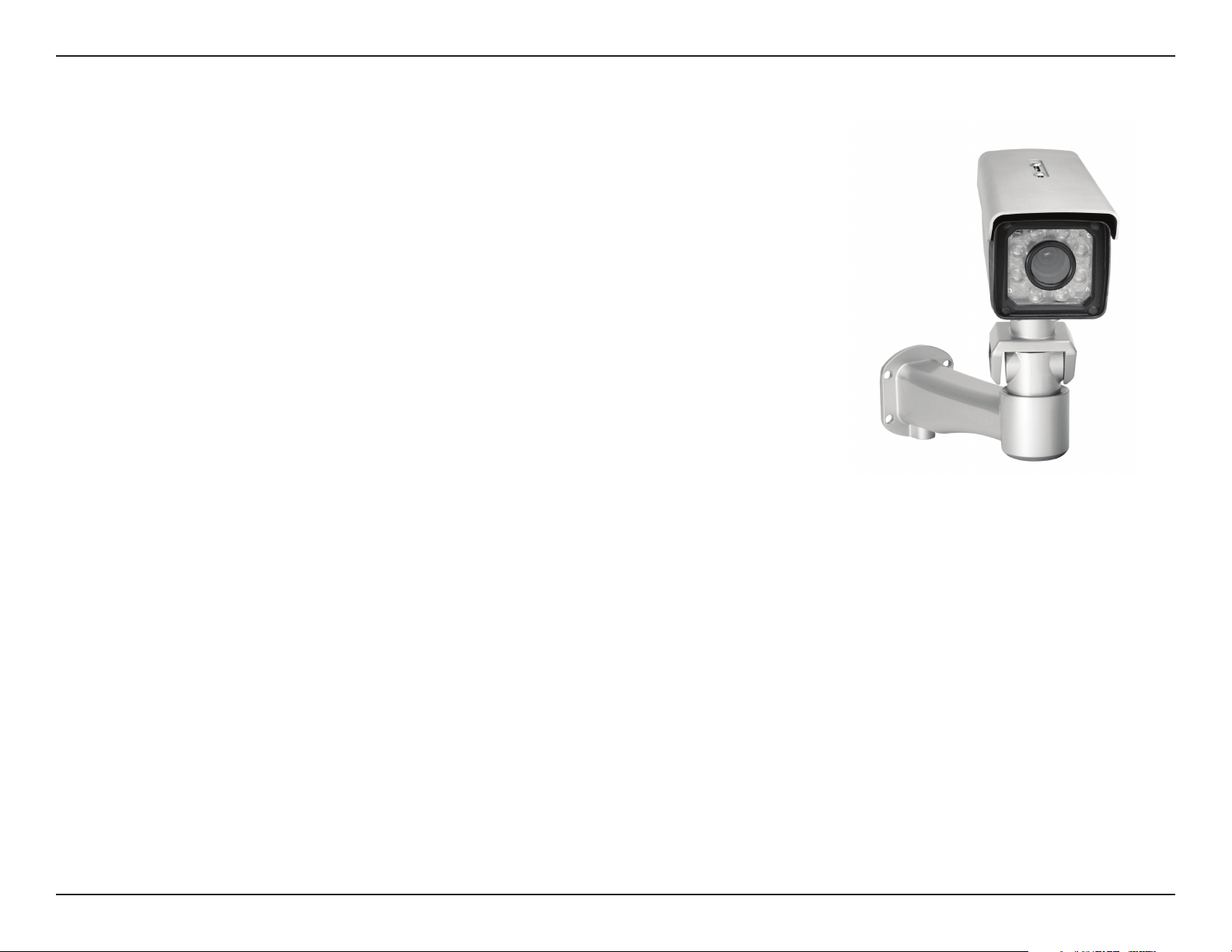
The DCS-7510 is a day & night outdoor PoE network camera with built-in infrared LEDs. Equipped with a highresolution CCD image sensor, this camera provides you with excellent image quality and level of detail. The
DCS-7510 is equipped with a varifocal 9~22mm lens that lets you manually change the focus length on desired objects.
The focus and zoom controls are located outside on the camera case for easy adjustments. A built-in Infrared Cut
Removable (ICR) lter in the DCS-7510 allows the camera to capture images in both good light and low light conditions
by adding or removing the infrared cut lter. This camera also has an auto-iris that automatically adjusts the exposure
according to the light conditions for optimum picture quality. The DCS-7510 can detect moving objects in total darkness,
for distances of up to 50 meters. Embedded with a powerful SoC (System-on-Chip), the camera provides high-quality,
real-time video compression in MPEG-4 and motion JPEG formats. These elements make the DCS-7510 an ideal
solution for 24-hour surveillance.
The DCS-7510 is housed in an IP66 certied weatherproof casing, which protects the camera against rain and dust.
The wire-in bracket design tightly assembles and protects the cables not only from outdoor wear and tear, but also
from criminal acts such as cable cuts. You can also connect the camera to I/O sensors such as IR sensors, switches
and alarm relays, and set up the system to send automated e-mail notications for unusual events.
A live feed from the camera can be accessed on a 3G mobile network by using a compatible mobile phone or PDA with
a 3G video player. The bundled D-ViewCam software is included to manage up to 32 cameras simultaneously, send
automated e-mail alerts, and record video to your hard drive when motion is detected or according to a set schedule.
The software allows you to manage and record videos to a Network Attached Storage (NAS) or a Network Video
Recorder (NVR) device.
Note: Use of audio or video equipment for recording the image or voice of a person without their knowledge and
consent is prohibited in certain states or jurisdictions. Nothing herein represents a warranty or representation that
the D-Link product provided herein is suitable for the end-user’s intended use under the applicable laws of his or her
state. D-Link disclaims any liability whatsoever for any end-user use of the D-Link product, which fails to comply with
applicable state, local, or federal laws.
3D-Link DCS-7510 User Manual
Page 4

Section 1 - Product Overview
• Supports a variety of Protocols: Supports TCP/IP networking, SMTP e-mail, HTTP, and other Internet related
protocols. The DCS-7510 can easily be integrated into Internet/Intranet applications because of its standards-based
features.
• Auto-Iris Lens & IR LEDs: Auto-iris lens automatically adjusts the lens exposure according to the varied lighting
conditions for optimum picture quality and the infrared LEDs for night surveillance.
• Built-in Infrared Cut Removable (ICR) Filter: The lter allows you to capture high-quality images during day and
night, by switching the infrared cut lter. The camera provides real-time video compression in MPEG-4 and motion
JPEG formats.
• Varifocal 9~22mm Lens: Equipped with a varifocal 9~22mm lens, the camera allows you to manually change the
focal length on desired objects.
• Remote Snapshots: Save snapshots directly from the Web browser to a local hard drive without installing any software.
This Snapshot feature allows you to conveniently capture images from a remote location.
Features
• Outdoor Deployment: Solid metal casing and wire-in bracket protect cables against damage. A built-in 802.3af compliant
Power over Ethernet (PoE) port simplies installation giving users the freedom to place the camera anywhere.
• Web Conguration: Using a web browser, an administrator can congure and manage the DCS-7510 directly and can
also create and control up to 10 accounts with different settings.
• 3G Mobile Surveillance: Access the camera’s live feed by using a compatible mobile phone or PDA with a 3G video
player, anywhere within a 3GPP service area.
• Bundled D-ViewCam Software: Manage up to 32 cameras simultaneously, send automated e-mail alerts, and record
videos to a NAS or NVR device.
• Applications: The DCS-7510 makes an ideal solution for detailed remote monitoring for places such as homes, ofces,
banks, hospitals, child-care centers, amusement parks and other industrial and public monitoring areas. Connect the
camera to I/O sensors, and set up the system to receive automated e-mail notication of all unusual events. The camera
can also be used for intruder detection (motion-detection mode), capture of still images and video for archiving, and can
be used for many more applications.
4D-Link DCS-7510 User Manual
Page 5
Section 1 - Product Overview
• D-Link DCS-7510 Day & Night Outdoor PoE Network Camera
• CAT5 Ethernet Cable
• Power Adapter 12V, 1.25A
• Wire-in Bracket
• Screwdriver (for external focus and zoom adjustments)
• Quick Installation Guide
• User Manual and Software on CD
• Screw and wall mount kit
If any of the above items are missing, please contact your reseller.
Note: Using a power supply with a different voltage rating than the
Product Overview
Package Contents
one included with the package may cause damage and will void the
warranty for this product.
System Requirements
• Windows® XP or Vista
• At least 256MB of memory (512MB recommended)
• An available Ethernet connection
• Internet Explorer 6 or higher
• VGA card resolution: 800 x 600 or higher
• CPU: 1.7GHz or higher (at least a 2.8GHz processor, 512MB memory, and a 32MB video card is required
for viewing multiple cameras and recording with the D-ViewCam software)
5D-Link DCS-7510 User Manual
Page 6
Section 1 - Product Overview
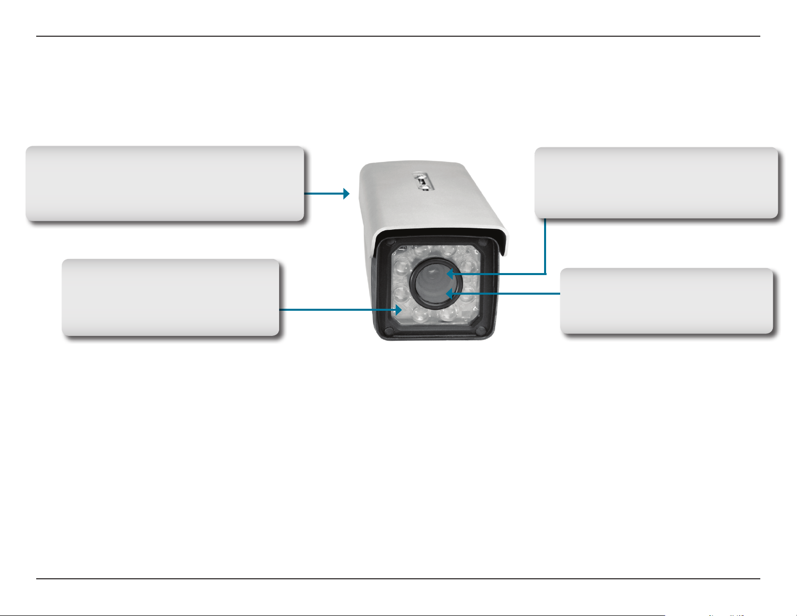
Hardware Overview
Front
Infrared Cut Removable (ICR) lter (inside)
Allows the camera to capture images in both good
light and low light conditions by switching the
infrared cut lter.
IR LEDs with Condenser
IR LEDs enables the camera to detect
moving objects in total darkness for
distances of up to 50 meters.
Auto-iris (inside)
Automatically adjusts the exposure according
to the light conditions for optimum picture
quality.
Varifocal Lens (inside)
The camera is equipped with a varifocal
9~22mm lens that allows for easy focal
length adjustment.
6D-Link DCS-7510 User Manual
Page 7
Section 1 - Product Overview
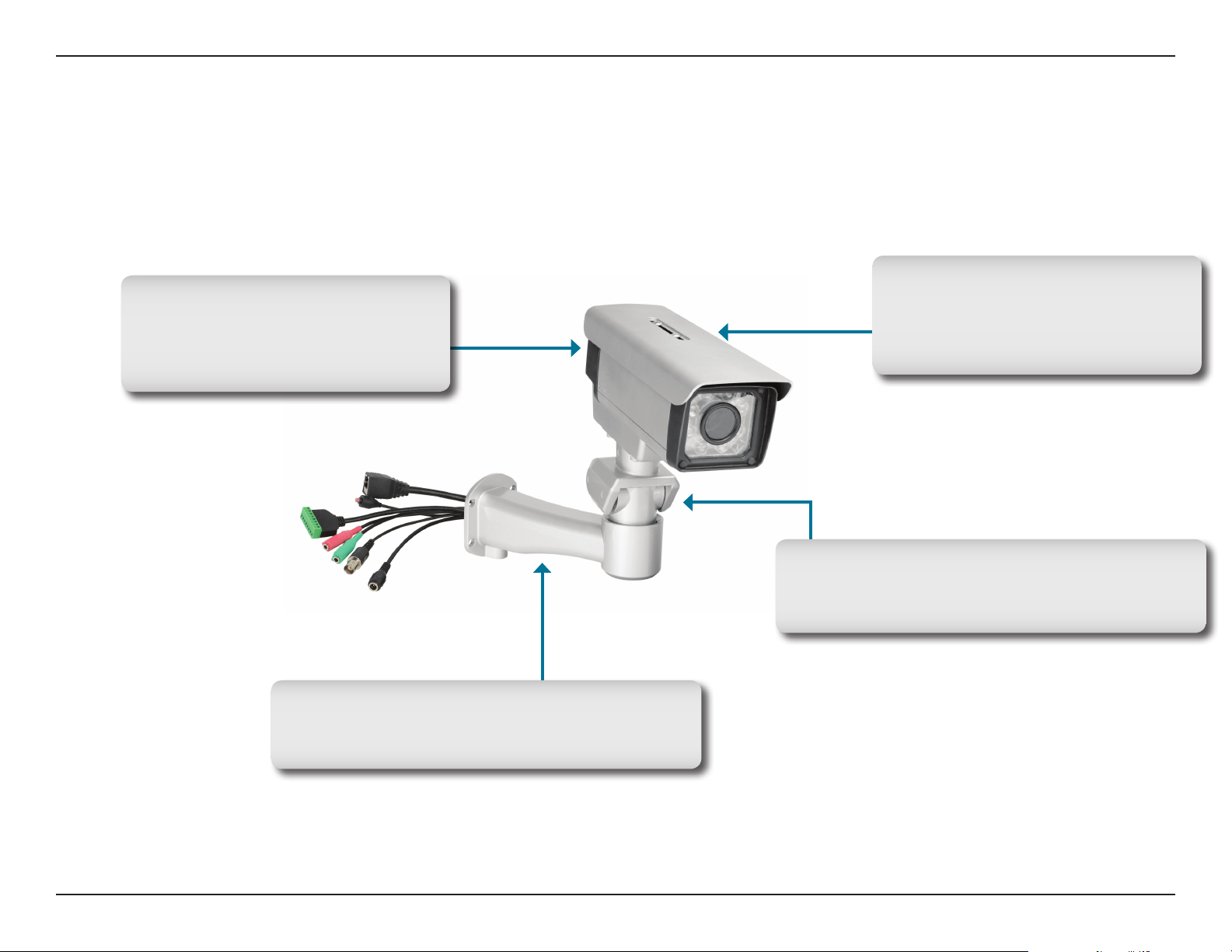
Weatherproof Casing
The camera is housed in an IP66
certied weatherproof casing, which
protects it against rain and dust.
Hardware Overview
Back
Adjustable Top Shield
Shields the camera sensor from direct
sunlight while providing air ventilation
for the camera.
Wire-in Bracket
Tightly assembles and protects the cables from
outdoor wear and tear.
Camera Bracket
Attaches to the camera and connects to the Wire-in
Bracket.
7D-Link DCS-7510 User Manual
Page 8
Section 1 - Product Overview
Hardware Overview
Connectors
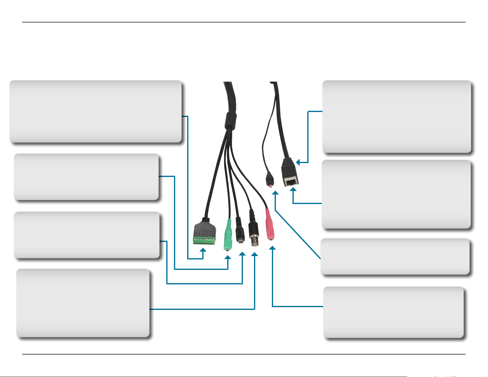
I/O Connector
The DCS-7510 offers a 8 pin-contact terminal block.
Two pairs are for input, one pair for output and
RS485 terminals. The connector provides a physical
interface to send and receive digital signals to and
from a variety of external devices.
Audio Out Connector
S pe a k ers ( no t in c l u de d ) ma y be
connected to the camera for a 2-way audio
communication.
DC Power Connector
Attach the Power Adapter to the DC
connector and connect the power adapter
to a power outlet.
Ethernet Cable Connector (PoE)
Plug the Ethernet cable into the RJ-45 PoE
connector. When connected to a PoE switch,
the built-in 802.3af compliant Power over
Ethernet (PoE) eliminates the need for a
nearby power outlet, giving you the freedom
to place the camera anywhere.
Link/Power LEDs
Lights up and changes color to indicate
the Link and Power status of your camera.
Green LED indicates Link up/Link down/
Trafc
Red LED indicates Power on/Power off
Reset Button
Resets the camera to factory defaults
when pressed for 10 seconds.
BNC
Th e BN C co nn ect or is u sed for
professional video connections. It
benefits users who integrate digital
IP cameras into a traditional system
(CCTV) for both analog and digital video
streaming purposes.
Microphone Connector
Connect an external microphone to the
microphone connector to hear what is
happening near your camera.
8D-Link DCS-7510 User Manual
Page 9
Section 1 - Product Overview
Hardware Installation
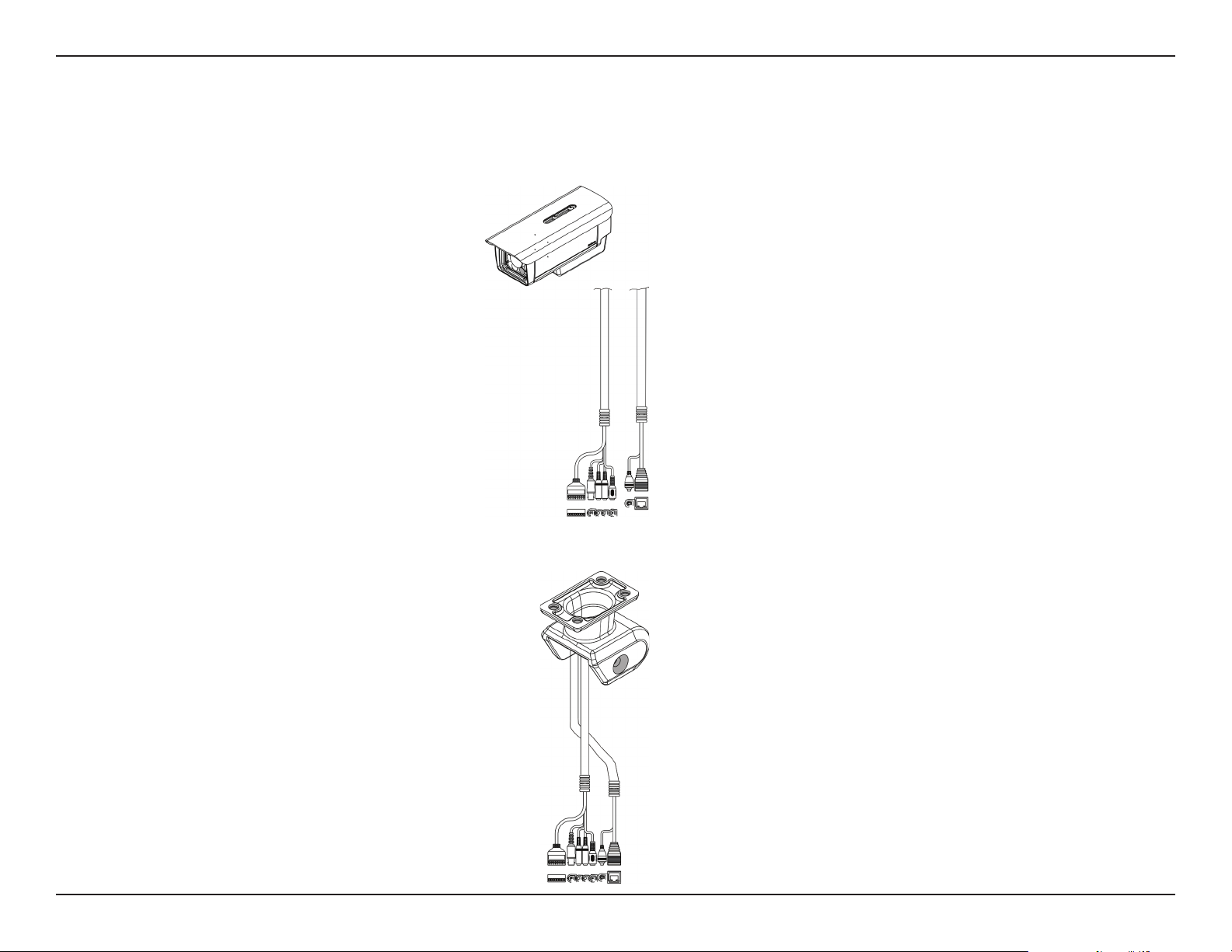
Mounting and Connecting the Camera
Step1. Straighten the two sets of cables from the camera side by side. (Diagram1)
Diagram 1
Step2. Start by passing the two sets of cables through the camera bracket. (Diagram 2)
Diagram 2
9D-Link DCS-7510 User Manual
Page 10
Section 1 - Product Overview
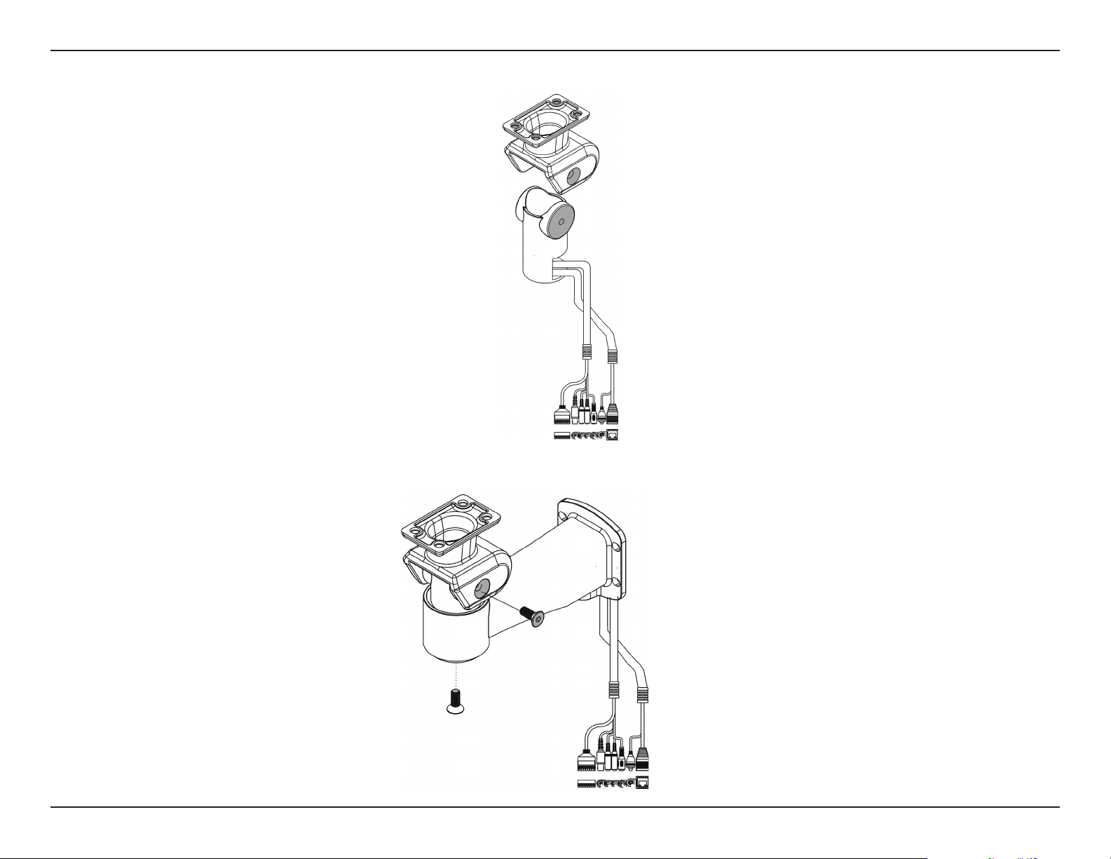
Step3. Next, continue passing the cables through the wire-in bracket, pulling them through the other end. (Diagram 3)
Diagram 3
Step4. Attach the camera bracket to the wire-in bracket using screws. (Diagram 4)
Diagram 4
10D-Link DCS-7510 User Manual
Page 11
Section 1 - Product Overview
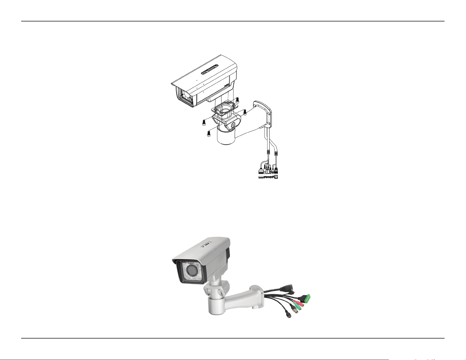
Step5. Finally, attach the camera on the top of the camera bracket using screws. (Diagram 5)
Diagram 5
Step6. Connect the cables as required. (Diagram 6)
Refer to the Hardware Overview, Connectors section for details on the different connectors.
Diagram 6
11D-Link DCS-7510 User Manual
Page 12
Section 1 - Product Overview
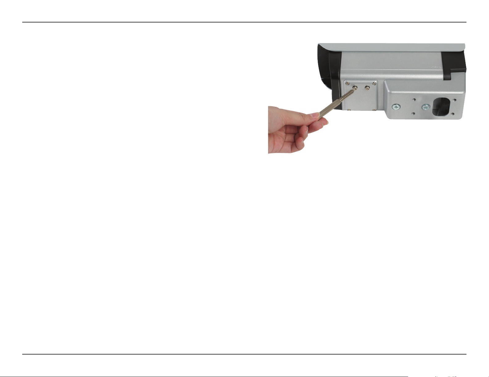
Focus and Zoom Adjustment
The focus and zoom controls are located on the outside of
the camera case for easy adjustments. Use the screwdriver
provided to adjust the focus and zoom of your camera.
Note: With a shorter focal length you will get a wider eld
of view, whereas a longer focal length narrows the eld of
view and allows you to zoom in more on an area.
12D-Link DCS-7510 User Manual
Page 13
Section 2 - Installation
Software Installation
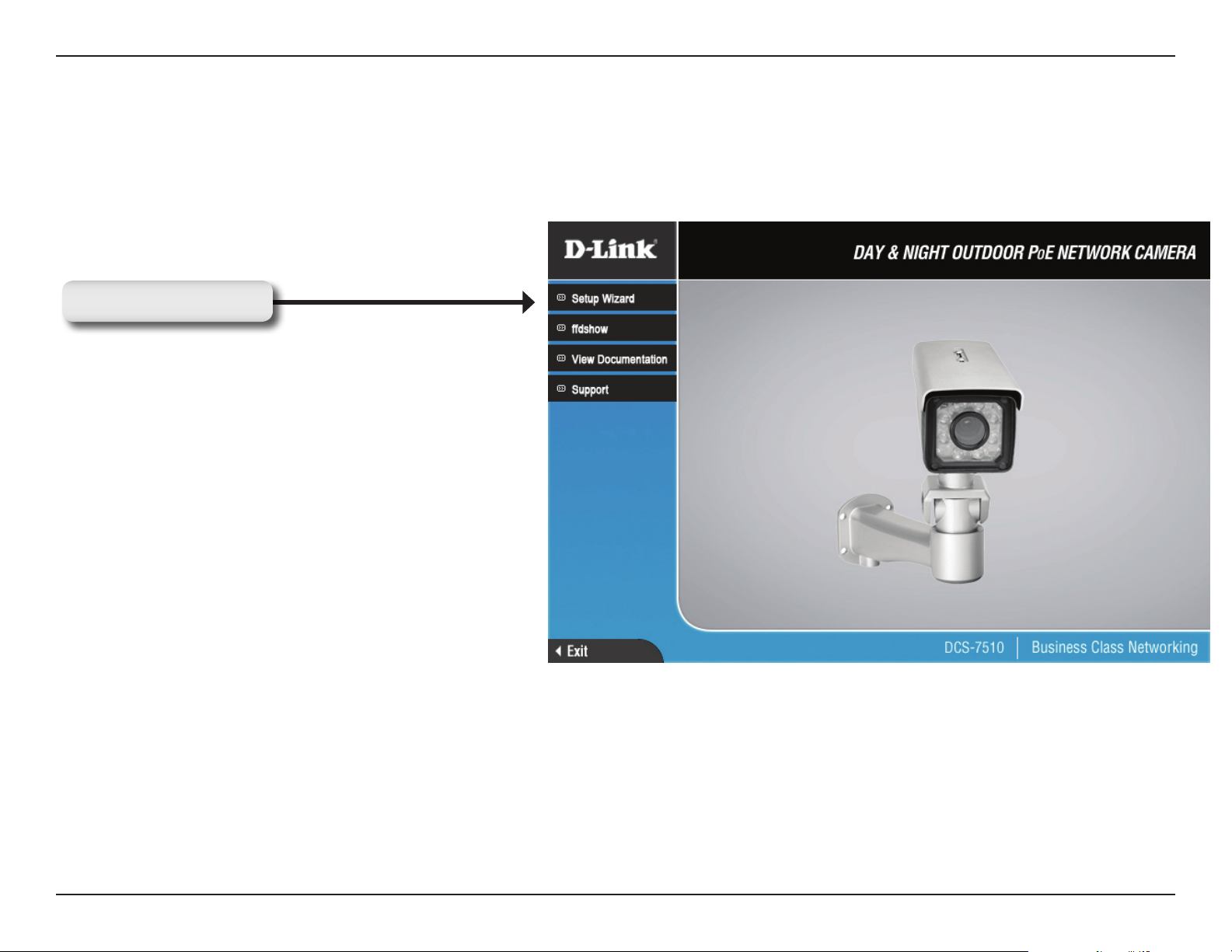
Insert the Installation DCS-7510 driver CD into your computer’s CD-ROM drive to start the autorun program. The
Setup Wizard will guide you through the entire installation process from connecting your hardware to conguring your
camera.
Click Setup Wizard
If the autorun program does not automatically start on your computer, go to Windows, click Start > Run. In the Run
command box type D:\DCS7510.exe, where D: represents your CD-ROM drive.
13D-Link DCS-7510 User Manual
Page 14
Section 2 - Installation
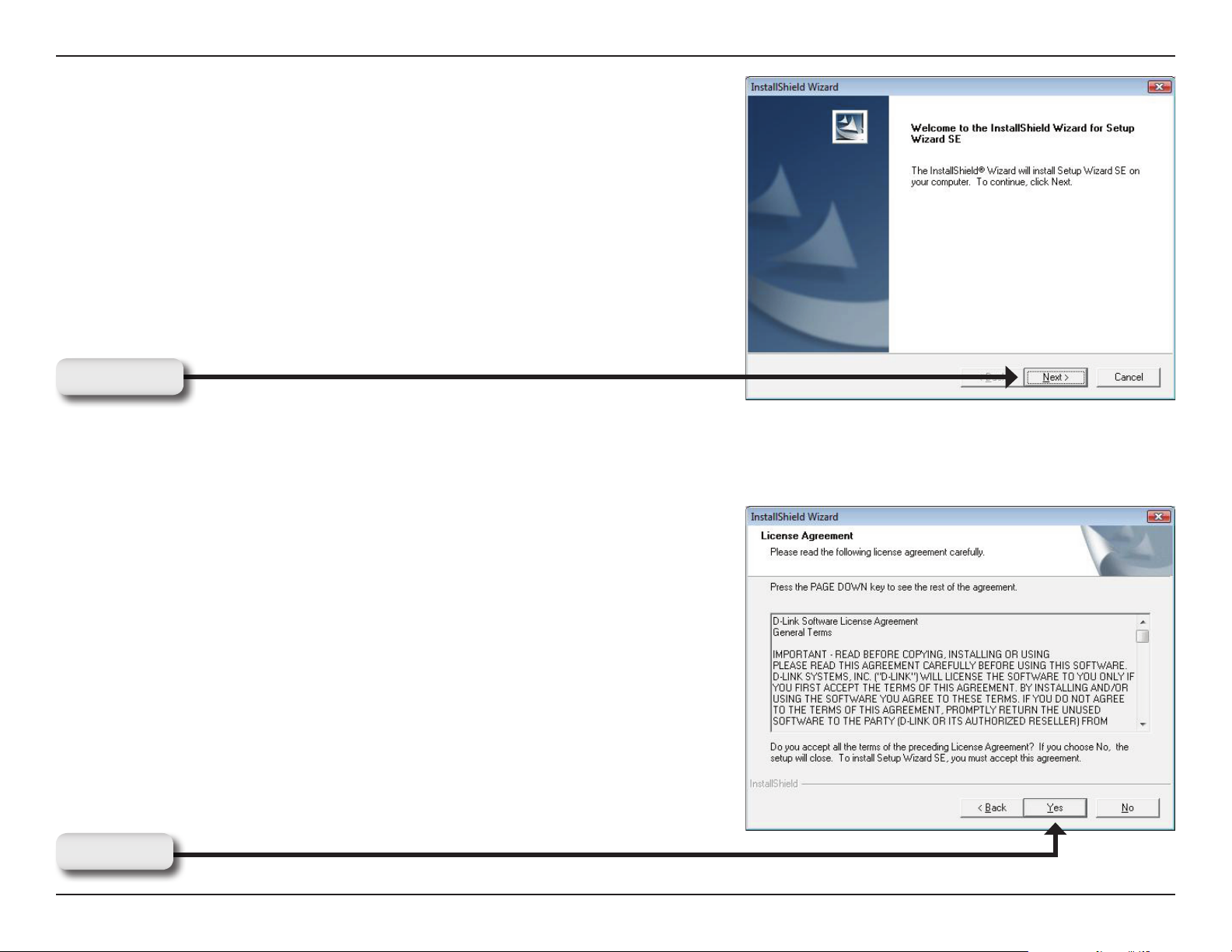
After clicking Setup Wizard, the following window will open.
Click Next to continue.
Click Next
Click Yes to accept the License Agreement.
Click Yes
14D-Link DCS-7510 User Manual
Page 15
Section 2 - Installation
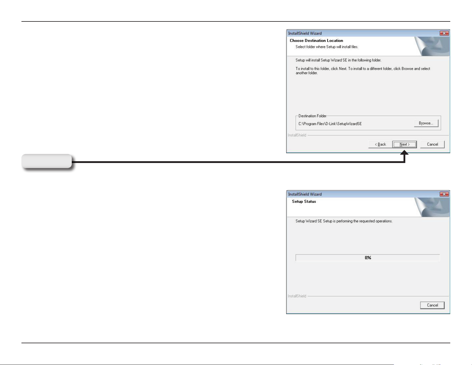
To start the installation process click Next.
Note: The installation may take several minutes to nish.
Click Next
15D-Link DCS-7510 User Manual
Page 16
Section 2 - Installation
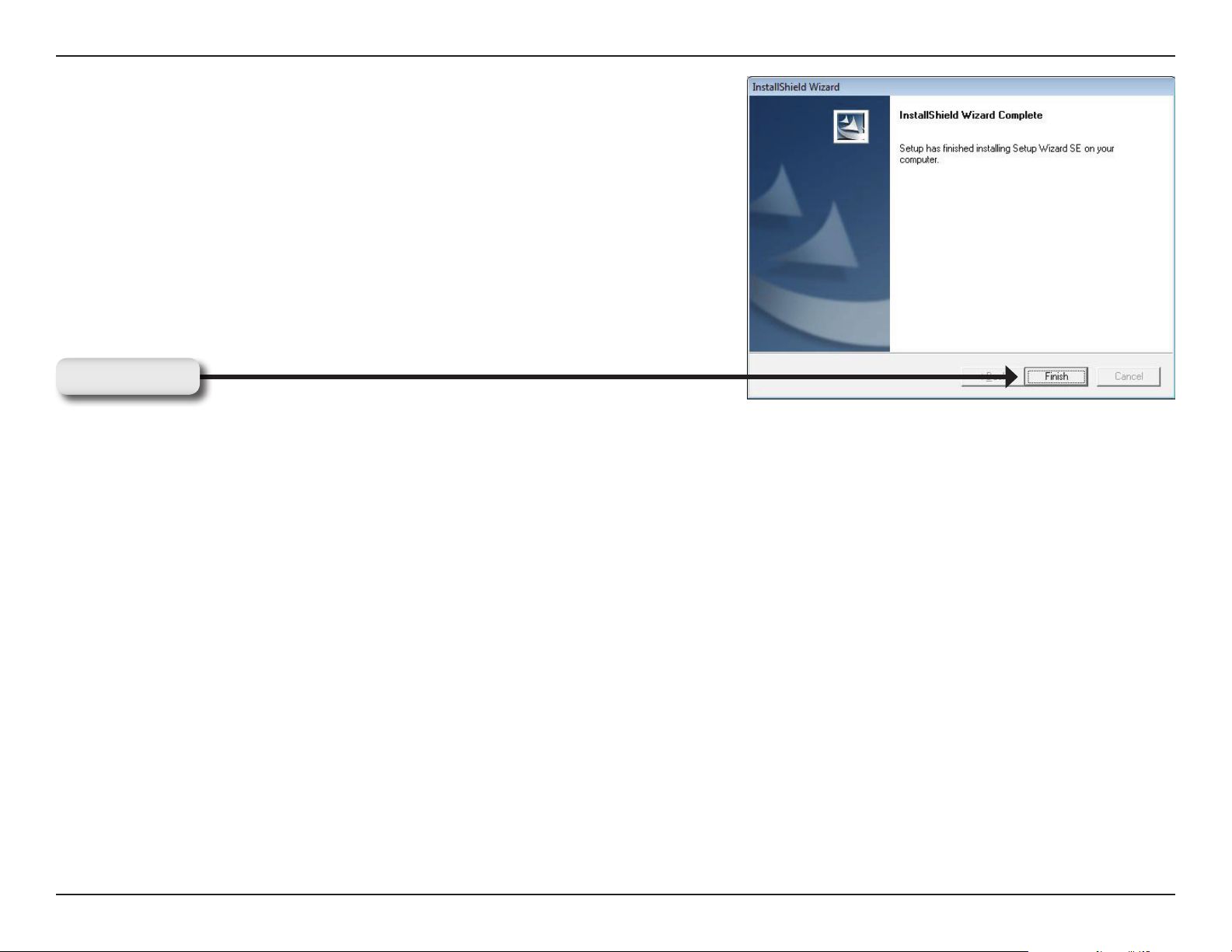
Click Finish to complete the installation.
Click Finish
16D-Link DCS-7510 User Manual
Page 17
Section 2 - Installation
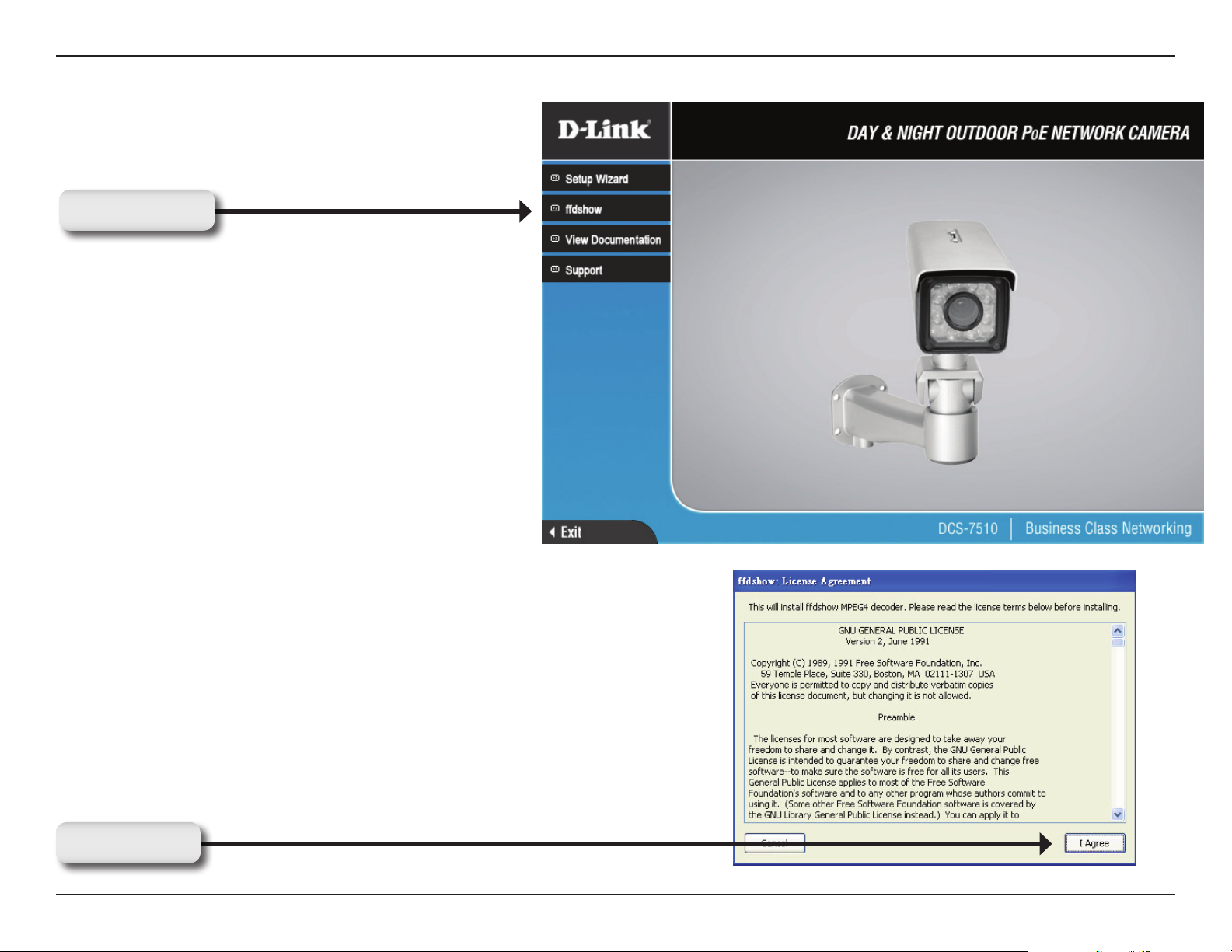
Click ffdshow from the autorun screen to install the proper codecs that will allow you to playback videos taken by the
DCS-7510.
Click ffdshow
Click I Agree
17D-Link DCS-7510 User Manual
Page 18
Section 2 - Installation
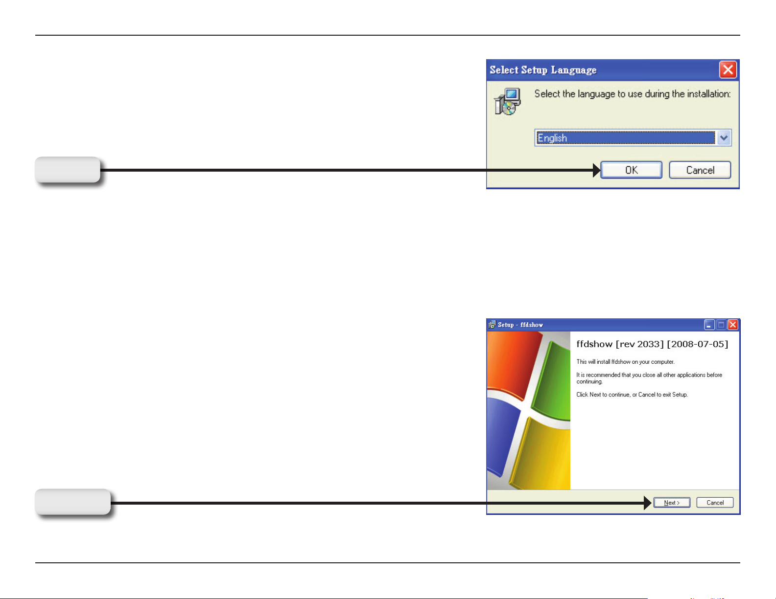
Select Language, and then click OK
Click OK
Select Language, and then click OK
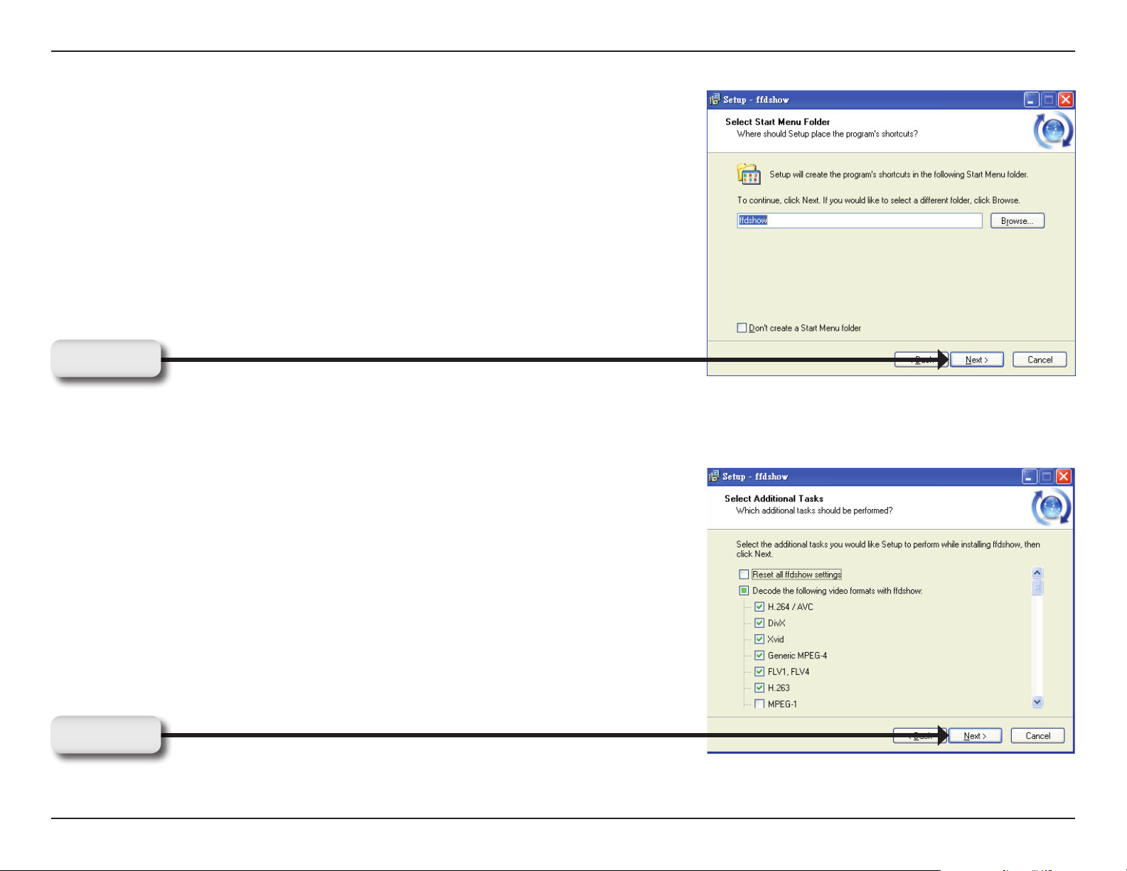
Click Next
18D-Link DCS-7510 User Manual
Page 19
Section 2 - Installation
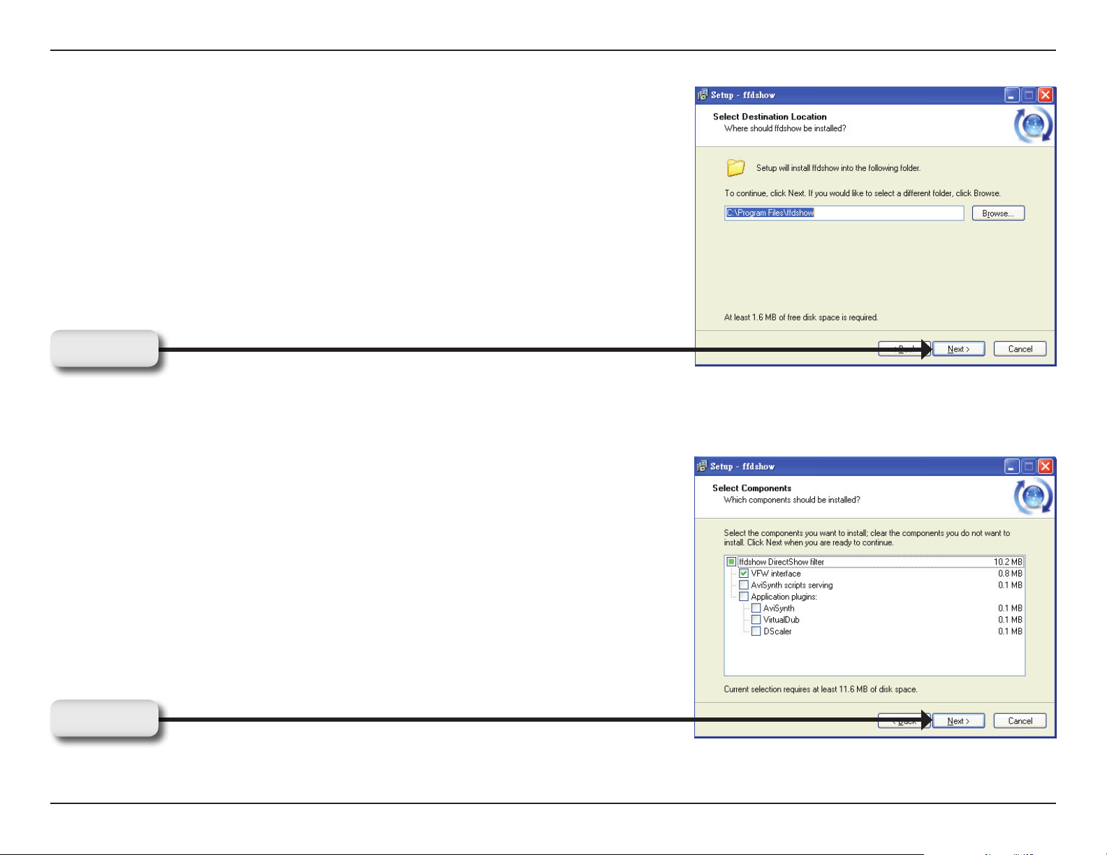
Click Next
Click Next
19D-Link DCS-7510 User Manual
Page 20
Section 2 - Installation
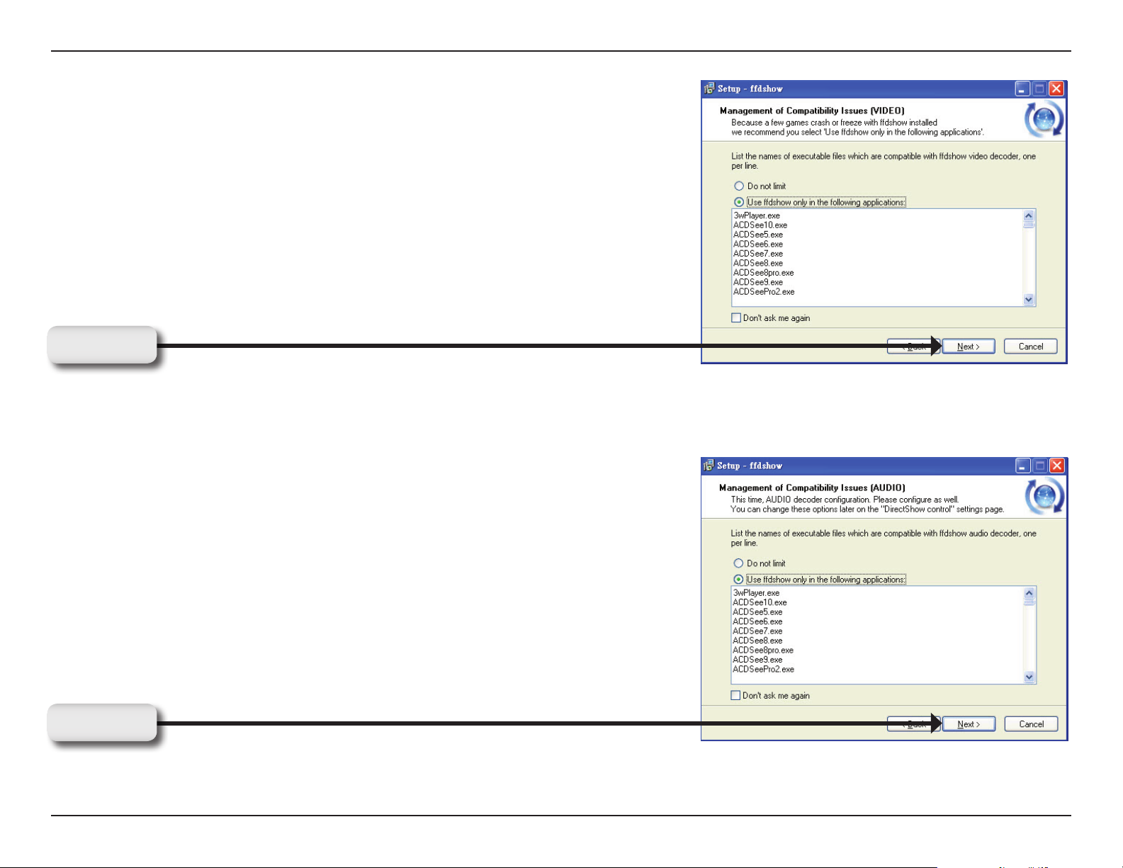
Click Next
Click Next
20D-Link DCS-7510 User Manual
Page 21
Section 2 - Installation
Click Next
Click Next
21D-Link DCS-7510 User Manual
Page 22

Section 2 - Installation
Select the speaker from your PC, and then clink Next
Click Next
Click Install
22D-Link DCS-7510 User Manual
Page 23

Section 2 - Installation
Installing
Click Finish
23D-Link DCS-7510 User Manual
Page 24

Section 3 - Configuration
Configuration
This section will help you congure your new D-Link Network Camera using the Setup Wizard.
Using the Setup Wizard
Click the D-Link Setup Wizard SE icon that was created in your Windows Start menu.
Click D-Link Setup Wizard SE
24D-Link DCS-7510 User Manual
Page 25

Section 3 - Configuration
The Setup Wizard will display the MAC address of the DCS-7510
and an IP Address (which may or may not be correct depending on
your DCS-7510 connection). If you have a DHCP server on your
network, there will be a valid IP Address displayed here. Click the
Wizard button to continue.
Enter the admin ID and password.
Note: The default Admin ID is admin with the password left blank.
Click Next
25D-Link DCS-7510 User Manual
Page 26

Section 3 - Configuration
Select DHCP if you want to get an IP address automatically from your
router or Internet service.
Click Next to continue.
Click Next
Alternatively, you can select Static IP to use the same IP address on
camera start up.
Click Next to continue.
Click Next
26D-Link DCS-7510 User Manual
Page 27

Section 3 - Configuration
Click Restart to save your settings and reboot your Network Camera.
Click Restart
Click Link to access the web conguration page. The Setup Wizard
will automatically open your web browser and enter the IP address
of your camera into a web browser.
In this example, the IP address is http://192.168.1.185.
Your DCS-7510 may have a different IP address.
Click Link
27D-Link DCS-7510 User Manual
Page 28

Section 3 - Configuration
Using the Configuration Menu
Using the Configuration Menu
After completing the Camera Installation Wizard, you are ready to use your camera. The camera’s built-in Web
conguration utility is designed to allow you to easily access and congure your DCS-7510. At the end of the
Setup Wizard, click Go To Camera, or enter the IP address of your camera into a web browser, such as Internet
Explorer. To log in, use the User name admin and the password you created in the Installation Wizard. If you did not
create a password, leave the password text box blank. After entering your password, click OK.
Note: If you are directly connecting your PC to the camera, or if you are using the camera on a closed network, the
default IP is 192.168.0.20.
Click OK
28D-Link DCS-7510 User Manual
Page 29

Section 3 - Configuration
Web-based Configuration Utility
Use the following sections to set up and congure your network camera:
• LIVE VIDEO
• SETUP
• MAINTENANCE
• STATUS
• HELP
29D-Link DCS-7510 User Manual
Page 30

Section 3 - Configuration
Live Video
LIVE VIDEO > Camera
This section shows your camera’s live video and event indicators. You can zoom in and out of the live video image
using your mouse. Left-click to zoom in and right-click to zoom out on the image.
You may also select your language setting using the drop-down menu.
Digital Input
Motion Trigger
Recording
This indicator will light up, when there is an
available digital input signal.
This indicator will light up, when an event is
triggered.
Note: Ensure that the video motion feature of
your camera is enabled.
This indicator will light up, when a recording is
in progress.
30D-Link DCS-7510 User Manual
Page 31

Section 3 - Configuration
You can access various functions by clicking on the buttons at the bottom of the window:
Video Prole: There are four different viewing profiles, which you can
configure in Setup > Audio and Video.
Full Screen: This allows you to view the video in full screen mode. To exit
full screen mode, press the ESC key on your keyboard.
Snapshot: Click to capture a snapshot image. The image will pop up in a
new window. You may save this image to a local hard drive.
Record Video: Clicking this button will start or stop recording video to the
file path specified with the Set Storage Folder button.
Set Storage Folder: You can change the folder where the video recordings
will be saved.
Start/Stop Audio: This button toggles the microphone on and off, allowing
you to hear audio from the area surrounding your camera.
Start/Stop Talking: This button toggles the speaker on and off, allowing
you to talk with others near your camera.
Start/Stop Digital Output: This will toggle the GP DO output on and
off.
IR LED ON/Off: This button can enable/disable the IR LEDs under the low
illumination environment. Note that the live video will turn to black and white
mode when IR LEDs turned on.
31D-Link DCS-7510 User Manual
Page 32

Section 3 - Configuration
Setup
SETUP > Setup Wizard
The setup wizard guides you through the initial setup of your
IP camera. You can use the Internet Connection Setup
Wizard for initial network setup, and you can use the Motion
Detection Setup Wizard to set up motion detection and
snapshots. Simply follow the instructions given in each step
of the wizard to quickly set up your camera.
Alternatively, you can manually set up your Internet
connection by clicking Manual Internet Connection Setup,
and you can manually set up motion detection options by
clicking on Manual Motion Detection Setup. You can also
see these settings by clicking on the menu on the left panel
(Network Setup / Motion Detection / Snapshot).
Internet Connection Setup Wizard
This wizard will guide you through a step-by-step process to congure your LAN and Internet conguration.
Click Next to continue.
Click Next
32D-Link DCS-7510 User Manual
Page 33

Section 3 - Configuration
Select DHCP if you are not sure which LAN settings
to use. This allows your camera to get an IP address
automatically from your router or Internet service.
Click Next
Select Static IP to manually set the IP address
information of your camera.
Click Next
33D-Link DCS-7510 User Manual
Page 34

Section 3 - Configuration
If you are using a PPPoE connection, check Enabled
and enter the Username and Password for your PPPoE
account. You can get this information from your Internet
service provider (ISP).
Click Next
If you have a Dynamic DNS account and would like the
camera to update your IP address automatically, select
Enable and enter your host information.
Click Next
Enter a name for your camera and click Next to
continue.
Click Next
34D-Link DCS-7510 User Manual
Page 35

Section 3 - Configuration
Congure the time to ensure that all events are triggered,
captured and scheduled at the right time. Click Next
to continue.
Click Next
If you selected DHCP mode, you will see the following
screen appear. Please note down this information in
order to access your camera on the network. Click
Apply to save your settings.
Click Apply
If you selected Static IP mode, you will see the following
screen appear. Please note down this information in
order to access your camera on the network. Click
Apply to save your settings.
Click Apply
35D-Link DCS-7510 User Manual
Page 36

Section 3 - Configuration
Motion Detection Setup Wizard
This wizard will guide you through a step-by-step process to set up Motion Detection on your IP camera. Click Next
to continue.
Click Next
This step allows you to enable or disable video motion
and control the sensitivity of your camera.
To draw a motion detection zone, select Draw motion
area, then click and drag your mouse over the areas of
the image you want to monitor for motion detection. You
can select Erase motion area to remove areas, and
you can also enter a Sensitivity for motion detection,
where 0% is the least sensitive setting and 100% is the
most sensitive setting. Click Next to continue.
Click Next
36D-Link DCS-7510 User Manual
Page 37

Section 3 - Configuration
This step allows you to specify how event notications
are sent from your camera, either through e-mail or
FTP. Make sure you enter all the relevant information
for your e-mail account or FTP server. Click Next to
continue.
Click Next
37D-Link DCS-7510 User Manual
Page 38

Section 3 - Configuration
You have completed the Motion Detection Wizard.
Click Apply to activate your settings.
Click Apply
38D-Link DCS-7510 User Manual
Page 39

Section 3 - Configuration
SETUP > Network Setup
Network Setup allows you to congure your LAN and Internet settings.
DHCP:
Connection:
Static IP Address:
IP Address:
Subnet Mask:
Default Gateway:
Primary DNS:
Select this to allow your camera to get an IP address automatically
from your router or Internet service. If you are not sure which
LAN settings to use, try using DHCP mode rst.
Select this to manually set the IP address information for your
camera.
Enter the IP address the camera should use.
The xed IP address.
Enter the subnet mask that the camera should use. The default
value is “255.255.255.0. This option is used to determine if the
destination is in the same subnet.
Enter the default gateway that the camera should use. The
gateway is used to forward frames to destinations in a different
subnet. Invalid gateway settings may cause transmission
failure.
Enter the IP address of the primary DNS server that the camera
should use. The primary DNS translates domain names to IP
addresses.
Secondary DNS:
Enter the IP address of the secondary DNS server that the
camera should use. The secondary DNS is used as a backup
for the primary server.
Note: If you need to use a static IP address and you do not know the network information, contact your Internet Service
Provider (ISP) for assistance.
39D-Link DCS-7510 User Manual
Page 40

Section 3 - Configuration
Enable UPnP:
Enable UPnP port
forwarding:
Enable PPPoE:
HTTP port:
RTSP port:
Universal Plug & Play (UPnP) allows Windows PCs to nd this
camera under “Network Neighborhood” without conguration.
Enables your camera to add port forwarding entries into the router
automatically.
Select this option if you are using a PPPoE service and enter
the User Name and Password for your PPPoE account. You can
get this information from your Internet service provider (ISP).
This is the port that allows the user to connect to the
camera’s
user interface. By default the port is set to 80. You may change
the port number if using multiple cameras.
This is the port that you use for RTSP streaming to mobile
devices or PDAs. By default the port is set to 554. You may
change the port number if using multiple cameras.
Click Save Settings to save your changes, or click Don’t Save Settings to discard your changes.
Note: Make sure you set up your router/gateway for Port Forwarding/Mapping; this will enable remote viewing of your
camera via the Internet. Please refer to your router’s instruction manual on how to forward ports.
40D-Link DCS-7510 User Manual
Page 41

Section 3 - Configuration
SETUP > Dynamic DNS
If you have a DSL or Cable service provider that changes your modem IP address periodically, Dynamic DNS (Domain
Name System - a method of keeping a domain name linked to a dynamic IP address) is useful. With the DCS-7510,
you can set up your DDNS service and the camera will automatically update your DDNS server every time it receives
a different IP address. Depending on the service, this update may take up to a few hours.
Enable DDNS:
Server Address:
Host Name:
User name:
Password:
Verify
Password:
Timeout:
Status:
Select to enable the DDNS function of the
camera.
Select a DDNS service provider from the drop-down
box or manually enter your server address.
Enter the Host Name of the DDNS service.
Enter your User Name for the DDNS service.
Enter the password for the DDNS service.
Re type the password for the DDNS service.
This sets the number of hours between DDNS
updates.
Indicates the current connection status of your
camera to your DDNS service.
Click Save Settings to save your changes, or click Don’t Save Settings to discard your changes.
41D-Link DCS-7510 User Manual
Page 42

Section 3 - Configuration
SETUP > Image Setup
Image Setup allows you to adjust the settings for your video image. A preview of this image will be shown in the live
video window in the middle of the screen.
Brightness:
Saturation:
Contrast:
This adjusts the brightness of the camera
image.
This adjusts the color saturation of the camera
image.
This adjusts the contrast of the camera image.
Hue:
This adjusts the color tone of the camera image.
Click Reset to Default to reset your settings.
42D-Link DCS-7510 User Manual
Page 43

Section 3 - Configuration
SETUP > Audio and Video
Audio and Video allows you to congure four video proles with different settings for your camera. You may also set
up different proles for your computer and mobile display. In addition, you may congure the audio (speakers and
microphone) settings for your camera.
Encode Type:
Resolution:
FPS:
BPS:
This sets the video codec used for the video
stream. You can choose MPEG-4 or MJPEG
(JPEG). Internet Explorer browsers can view both
MPEG-4 and MJPEG video streams, and non-IE
browsers can only view MJPEG video streams.
This sets the display resolution of the video
stream. The following options are:
• QQVGA@176x120 - Usually set for handheld
devices.
• QVGA 352x240 - Standard setting for viewing
from mobile phones and PDAs.
• VGA@704x480 - Standard setting for viewing
from a PC.
This sets the target number of Frames Per Second
(FPS) for the video stream. Higher frame rates will
provide smoother video.
This sets the target bitrate of the video stream.
Higher bitrates will provide better quality video.
JPEG Quality:
This sets the JPEG quality of any manual
snapshots you take when this video prole is
selected.
43D-Link DCS-7510 User Manual
Page 44

Section 3 - Configuration
RTSP URL:
IR LED:
Enable Speaker:
This setting allows you to set a sufx for your
camera’s RTSP URL so you can view your
camera’s video with this video prole’s settings.
For example, if you enter “mpeg4” as your RTSP
URL setting and your camera’s IP is 192.160.0.20,
you can view your camera’s video with these
settings through 192.160.0.20/mpeg4.
You can setup the IR LED to auto or manual.
• Auto – Camera sensor will auto turn on/off when
• On/Off – User can turn On/Off the built-in IR
Checking this box will enable you to send audio
to an external speaker (not included) attached to
the external speaker jack of your camera. This will
allow you to speak with another person through
your camera.
the sensor detect the environment is in
low illumination.
LEDs. This function is very useful under
low illumination environment. Note that
the live view will turn to black and white
mode when IR LEDs turned on.
Volume:
Enable
Microphone:
Volume:
This sets the volume level of the external
speaker.
Checking this box will enable you to listen to audio
picked up by the microphone. This will allow you to hear what is happening near your camera.
This sets the volume level of the incoming audio.
Note: Higher frame size, frame rate and bit rates will give you better video quality, but they will also require more
network bandwidth. For best viewing results on a mobile phone, we suggest setting the Frame Rate to 5 fps and bps
to 20 Kbps.
Click the Save Settings to save your changes, or click Don’t Save Settings to discard your changes.
44D-Link DCS-7510 User Manual
Page 45

Section 3 - Configuration
SETUP > Motion Detection
This option allows you to set up Motion Detection on your IP camera. In order to use motion detection, you must rst
check the Enable Video Motion checkbox. You can then click on the video window and draw motion detection zones
by clicking and dragging your mouse. Red areas indicate areas that will be monitored for motion.
Enable Video
Motion:
Sensitivity:
Draw motion
area:
Erase motion
area:
Clear:
Select to turn on the motion detection feature of
your camera.
This setting adjusts how sensitive the camera
will be to motion, where 100% will be the most
sensitive setting and 0% will be the least sensitive
setting.
Select to draw motion detection area by dragging
your mouse in the window ( as indicated by the
red box).
Select to erase your motion detection area by
dragging your mouse in the window.
Click this button to clear all motion detection
areas.
Click Save Settings to save your changes,
or click Don’t Save Settings to discard
your changes.
45D-Link DCS-7510 User Manual
Page 46

Section 3 - Configuration
SETUP > Time and Date
Time and Date allows you to congure, update and maintain the internal system clock for your camera. You can
manually set your time zone from the drop-down box or automatically synchronize your time using Network Time
Protocol (NTP) server.
Time Zone:
Enable Daylight
Saving:
Auto Daylight
Saving:
Set date and time
manually:
Offset:
Synchronize with
NTP Server:
NTP Server:
Select your time zone from the drop-down menu.
Select to enable daylight saving time.
This option allows your camera to automatically
congure the Daylight Saving setting.
Select to manually congure the Daylight Saving
date and time.
Select to adjust the Daylight Saving offset time
that will be used.
Select to allow the camera to automatically
synchronize its clock with an NTP server.
Network Time Protocol (NTP) synchronizes the
DCS-7510 with an Internet time server. Choose
the one that is closest to your location.
Set date and time
manually:
Select to manually set the time and date. You
can then use the drop-down boxes to select the
current Year, Month, Day, Hour, Minute, and
Second.
You can also click Copy Your Computer’s Time
Settings to automatically ll in the drop-down
boxes with the current time and date from your
computer.
46D-Link DCS-7510 User Manual
Page 47

Section 3 - Configuration
SETUP > Recording
Recording allows you to congure recording settings and scheduling.
Enable
Recording:
Samba Auth:
Select to enable the recording feature.
Select Anonymous if no user name or password is required
to access your Samba drive. If you require a user name and
password to log in to your Samba drive, select Account and ll
in the following information:
User name: Enter the user name required to access your
Samba drive.
Password: Enter the password required to access your Samba
drive.
Password conrm: Re-enter the password required to access
your Samba drive for verication.
Server: Enter the name or the IP of the server where your
Samba drive is located.
Shared Folder: Enter the name of your shared folder.
Test: Click this button to test the connection of the Samba
network drive.
Samba status: Displays the connection status which is
determined by the system. Click Get Status
to refresh the status.
47D-Link DCS-7510 User Manual
Page 48

Section 3 - Configuration
Recording Options
Resolution:
Record until:
When Storage is
full:
Event Based:
Motion detection
triggered recording:
Prerecord:
Postrecord:
Select the pre-dened prole you wish to use to record
video.
Select to adjust how much free space must remain when
recording. It is suggested that you set this to at least 32MB
to allow for enough buffer space for the camera to record
with.
When your storage device is full or has reached the free
space limit specied in Record until, you can choose to stop
recording, or you can have the camera delete old recordings
to free space for new recordings to be saved.
Allow you to record video when specic events happen.
Enabling this option will set the camera to record video when
motion is detected by the camera.
Preset amount of time before motion recording is triggered.
Preset amount of time after motion recording is triggered.
Example: Using motion detection triggered recording and
setting Prerecord to 5 seconds and Postrecord to 9 seconds,
the camera will save video from 5 seconds before motion was
detected to 9 seconds after motion was detected.
Continuous:
Scheduled:
This will set the camera to record continuously.
Select to manually congure the start and end time for
recording.
Click Save Settings to save your changes, or click Don’t Save Settings to discard your changes
.
48D-Link DCS-7510 User Manual
Page 49

Section 3 - Configuration
Creating a Samba network drive for saving video
Follow the instructions below to create a simple Samba network drive on your Windows PC.
Right-click on a folder and select 1. Sharing and Security
and then select Share this folder.
Enter a Share name you would like to use for the folder, 2.
then click Permissions.
Check the 3. Full Control / Allow Everyone group box.
For your camera’s 4. Recording settings, select Anonymous
for the Samba Auth, your computer’s IP address for the
Server, and the Share name you chose for the Shared
Folder.
Click 5. Test to test your connection.
Click Save Settings to save your changes, or click
Don’t Save Settings to discard your changes.
49D-Link DCS-7510 User Manual
Page 50

Section 3 - Configuration
SETUP > Snapshot
Snapshot enables your camera to take snapshots when motion is detected. Snapshots can be sent to an e-mail
address and/or to an FTP server.
Enable
Snapshot:
Event Based:
Continuous
(FTP only):
Scheduled
(FTP only):
E-mail
Address:
Check this box to enable the snapshot feature.
Select one or more events to trigger a snapshot, such as Motion
Detection, D/I Signal 1 and D/I Signal 2.
This will set the camera to take snapshots continuously at
intervals specified in FTP Server > Interval below. You
can only save to an FTP server when taking continuous
snapshots.
This will set the camera to take snapshots continuously at
intervals specied in FTP Server > Interval below according
to schedule you dene by checking days and entering the
times you want to record between. You can only save to an
FTP server when taking scheduled snapshots.
The camera will send the snapshots to the e-mail address
specied in the following text boxes. If you do not know what
to enter for the User Name, Password, or SMTP Mail Server,
contact your e-mail service provider for details.
User Name:
Password:
SMTP Mail
Server:
Enter the username or login name for your e-mail
account.
Enter the password for your e-mail account.
Enter the SMTP server for your e-mail account.
50D-Link DCS-7510 User Manual
Page 51

Section 3 - Configuration
Sender E-mail
Address:
Recipient E-mail
Address:
Port:
Test:
FTP Server:
Host name:
Path:
Enter the e-mail address you want to appear as the “From:”
e-mail address in the snapshot e-mail.
Enter the e-mail address you want to send your snapshots
to.
Enter the port used by your SMTP server.
Click this button and the camera will take a snapshot and then
will try to upload it to your FTP server using the settings you
have entered.
When selected, the camera will send the snapshots it takes
to the e-mail address specied in the text elds. If you do not
know what information to enter, contact the administrator of
the FTP server for details.
Enter the host name of your FTP account.
Enter the directory or path where the images will be uploaded to (for
example: \pub\images).
Prex
Filename:
Port:
Passive mode:
Enter the prex you want to attach to your snapshot les.
Enter the port used by the FTP server. The default port is
25.
If your FTP server requires you to use passive mode, check
this box. Some FTP servers allow clients to use passive mode
when connecting to an FTP. The server uses random ports
for transfer.
Click Save Settings to save your changes, or click Don’t Save Settings to discard your changes.
51D-Link DCS-7510 User Manual
Page 52

Section 3 - Configuration
SETUP > Digital Output
Digital Output (DO) feature enables you to congure your DO port to send signals whenever certain events occur.
Enable D/O
signal:
Trigger Event:
This enables the D/O to send a signal when there
is a triggered event.
Use the checkboxes to congure the camera to
send a signal through the D/O port whenever
motion is detected, or when a signal is detected
on D/I port 1 or D/I port 2.
Click Save Settings to save your changes, or click Don’t
Save Settings to discard your changes.
52D-Link DCS-7510 User Manual
Page 53

Section 3 - Configuration
SETUP > RS-485
You may congure the RS-485 settings or communication specications (baud rate, data bit, stop bit, and parity bit)
for your camera. RS-485 is a serial communication method for computers and devices. For your camera, RS-485 is
used to control a PAN/TILT device, such as an external camera enclosure to perform PAN and TILT movement.
Support PAN-
TILT:
Protocol:
ID:
Baud Rate:
Data Bit:
Stop Bit:
Once you enable this feature, a control panel will be displayed
on the Live Video window that provides control over an external
camera enclosure through the RS-485 signals.
Select the protocol type from the drop-down box.
This is the identier for each RS-485 device. The ID range is from
1 to 255.
Enter the Baud Rate settings required by your RS-485
equipment. If you are not sure what settings to use, check your
RS-485 equipment’s User Manual. The default value is 2400.
The range is from 2400 to 38400 bps.
Enter the Data Bit settings required by your RS-485 equipment.
If you are not sure what settings to use, check your RS-485
equipment’s User Manual. The default value is 8.
Enter the Stop Bit settings required by your RS-485 equipment.
If you are not sure what settings to use, check your RS-485
equipment’s User Manual. The default value is 1.
Parity Bit:
Enter the Parity Bit settings required by your RS-485 equipment.
If you are not sure what settings to use, check your RS-485
equipment’s User Manual.
For example, if the data is 011, for even parity, the parity bit is
0 to keep the number of logic-high bits even. If the parity is odd,
the parity bit is 1, resulting in 3 logic-high bits.
Click Save Settings to save your changes, or click Don’t Save Settings to discard your changes.
53D-Link DCS-7510 User Manual
Page 54

Section 3 - Configuration
MAINTENANCE > Admin
Here, you can modify the Admin password and manage users. You can also use this section to congure the OSD
settings for your camera.
Admin Password
Setting:
New Password:
Retype
Password:
Add User
Account:
User Name:
This section lets you change the admin password
used to log in to the camera and adjust settings.
After installing the camera for the rst time, it is
highly recommended that you change the admin
password for security purposes.
Enter the new admin password.
Enter the new admin password again for verication.
After entering the new password again, click Save
to save your changes.
The admin can create user accounts to allow
others to log in to your camera to view the live
camera feed.
Enter the User Name you wish to use for the new
user account.
New Password:
Retype
Password:
Enter the password for the new user account.
Re-enter the password for the new user account
for verication. After entering the password again,
click Add to create the new user account.
54D-Link DCS-7510 User Manual
Page 55

Section 3 - Configuration
User List:
Device Setting:
Camera Name:
Enable OSD:
Label:
Show time:
You can view the current list of users by using the
drop-down box. You can also delete a user by
selecting them with the drop-down box, and then
clicking Delete.
You can change various other settings for your
camera.
Create a unique name for your camera, in which
you can access the camera by using this name in
your web browser. For example: http://DCS-7510
(by default).
Select to enable the On-Screen Display feature
for your camera.
This is the text label that will appear on the
OSD.
Select to display the time-stamp on the video
screen.
LED light:
This will turn the camera’s front LED indicator on
or off.
Click the Save to save your changes.
55D-Link DCS-7510 User Manual
Page 56

Section 3 - Configuration
MAINTENANCE > System
This screen allows you to save and restore the camera’s current conguration. You can also reset all settings to factory
default or reboot the device.
Save To Local Hard
Drive:
Local From Local
Hard Drive:
Restore To Factory
Default:
Reboot Device:
Click Save Conguration to save the current
conguration to a hard drive.
To load a saved conguration, click Browse to
select a conguration le from your hard drive,
then click Load Conguration to load the new
conguration.
Reset your camera and restore the factory settings
to your camera by clicking Restore Factory
Defaults.
Click this button to reboot your camera.
56D-Link DCS-7510 User Manual
Page 57

Section 3 - Configuration
MAINTENANCE > Firmware Upgrade
Your current rmware version and date will be displayed on
this page. Here, you can also upgrade your rmware with
a new version.
To upgrade your rmware, go to support.dlink.com.tw and
download the latest rmware to your computer’s hard drive.
Click Browse, select the rmware le, then click Upload.
While the rmware is being upgraded, do not turn off your
computer or camera, and do not disconnect your network
connection from your computer or camera. Upgrading the
rmware will not change any of your system settings, but it
is recommended that you save your system conguration
before doing a rmware upgrade.
Note: It is recommended that you use a wired connection for
your computer and camera when upgrading the rmware.
57D-Link DCS-7510 User Manual
Page 58

Section 3 - Configuration
STATUS > Device Info
This Device Info screen shows you various information about your camera and its current settings.
58D-Link DCS-7510 User Manual
Page 59

Section 3 - Configuration
STATUS > Logs
The log shows you a list of events that have happened recently. You can download the log by clicking Download, or
you can empty the log by clicking Clear.
59D-Link DCS-7510 User Manual
Page 60

Section 3 - Configuration
Help
The Help screen provides you with support information about the DCS-7510 for your reference.
60D-Link DCS-7510 User Manual
Page 61

Section 5 - Troubleshooting
Troubleshooting
1. What is a Network Camera?
An Network Camera is a standalone system that connects directly to an Ethernet or Fast Ethernet network whereas
conventional PC Cameras require connection to a powered PC to function. An Network Camera is an all-in-one
system with a built-in CPU, providing a low cost web-based solution that can transmit high quality video images
for monitoring. The Network Camera can be managed remotely, and can be accessed and controlled from any PC
locally or through the Internet via a Web browser.
2. What is the maximum number of users that can be allowed to access DCS-7510 simultaneously?
The maximum number of users that can log onto the Network Camera at the same time is 10. Please keep in mind
that the overall performance of the transmission speed will slow down when a large number of users are logged on.
3. What algorithm is used to compress the digital image?
MPEG-4 and MJPEG are used to provide high quality images at low bandwidths.
4. Can I capture still images from the Network Camera?
Yes. You may record snapshots using the snapshot feature on the Home page. When viewing this page, press the
“snapshot” button to capture the image and save it to your hard drive.
5. What network cabling is required for the Network Camera?
The Network Camera uses Category 5 UTP cable for 10Base-T and 100Base-TX networking.
6. Can the Network Camera be used as a webcam for my computer?
No, the DCS-7510 Network Camera only functions through a Fast Ethernet network.
7. Can the DCS-7510 be connected to the network if it consists of only private IP addresses?
Yes, the Network Camera can be connected to a LAN with private IP addresses.
8. Can the DCS-7510 be installed and work if a rewall exists on the network?
61D-Link DCS-7510 User Manual
Page 62

Section 5 - Troubleshooting
If a rewall exists on the network, port 80 needs to be opened for ordinary data communication, streaming audio,
streaming video. The DCS-7510 uses port 5002 for streaming audio and port 5003 for streaming video. These
ports or the ports you specify from the Advanced Tab in the Conguration screen, needs to be opened.
9. Why am I unable to access the DCS-7510 from a Web browser?
Ensure that the ports congured for the DCS-7510 on the router or rewall are correct. In order to do that, you
need to determine if the DCS-7510 is behind a router or rewall and then properly congure the ports of your
DCS-7510. Other possible problems might be due to the network cable. Try replacing your network cable. Test the
network interface of the product by connecting a local computer to the unit, with an Ethernet crossover cable. If the
problem is not solved the Network Camera might be faulty.
10. Why does the Network Camera work locally but not externally?
This might be caused by the rewall protection on your network. You may have to change the rewall settings in
order for the Network Camera to be accessible outside your local LAN. Check with the Network Administrator and
ensure that the Network Camera isn’t conicting with any Web server you may have running on your network.
The default router setting might be a possible reason. Check that the conguration of the router settings allow the
Network Camera to be accessed outside your local LAN.
11. I connected the Network Camera directly to a computer with a Ethernet cable and received a Windows
error upon running the Installation Wizard.
This Windows error will occur if the Network Camera is connected to a computer that is not properly congured
with a valid IP address. Turn off DHCP from the Network Settings in Windows and congure the computer with a
valid IP address, or connect the camera to a router with DHCP enabled. This error can also occur if the Installation
Wizard icon is clicked more than once starting from the setup wizard.
12. The images appear to be of poor quality, how can I improve the image quality?
Make sure that your computers display properties are set to at least 6-bit color. Using 16 or 256 colors on your
computer will produce dithering artifacts in the image, making the image look as if it is of poor quality. In the Image
Setup section of the web interface, you can adjust image related parameters including brightness, contrast, and
saturation. Please refer to the Setup > Image Setup section for detailed information.
62D-Link DCS-7510 User Manual
Page 63

Section 6 - DI/DO
DI/DO
DI
DO Connects to an alarm or buzzer.
485+/485-
Receives signals from a motion detector or any other external
security device.
Connects to an RS-485 interface for controlling auxiliary
equipment such as an external camera enclosure to perform
PAN and TILT movement.
63D-Link DCS-7510 User Manual
Page 64

Appendix A - Networking Basics
Networking Basics
Check your IP address
After you install your new D-Link adapter, by default, the TCP/IP settings should be set to obtain an IP address from
a DHCP server (i.e. router) automatically. To verify your IP address, please follow the steps below.
Click on Start > Run. In the run box type cmd and click OK.
At the prompt, type ipconfig and press Enter.
This will display the IP address, subnet mask, and
the default gateway of your adapter.
If the address is 0.0.0.0, check your adapter
installation, security settings, and the settings
on your router. Some rewall software programs
may block a DHCP request on newly installed
adapters.
If you are connecting to a wireless network at a
hotspot (e.g. hotel, coffee shop, airport), please contact an employee or administrator to verify their wireless network
settings.
64D-Link DCS-7510 User Manual
Page 65

Appendix A - Networking Basics
Assigning a Static IP Address
If you are not using a DHCP capable gateway/router, or you need to assign a static IP address, please follow the steps
below:
Step 1
Windows® XP - Click on Start > Control Panel > Network Connections.
Windows® Vista - From the desktop, right-click My Network Places > Properties.
Step 2
Right-click on the Local Area Connection which represents your D-Link network adapter and select Properties.
Step 3
Highlight Internet Protocol (TCP/IP) and click Properties.
Step 4
Click Use the following IP address and enter an IP address that is on the same subnet as your network or the LAN
IP address on your router.
Example: If the camera´s LAN IP address is 192.168.0.1, make your IP address
192.168.0.X where X is a number between 2 and 99. Make sure that the number
you choose is not in use on the network. Set Default Gateway the same as the LAN
IP address of your router (192.168.0.1).
Set Primary DNS the same as the LAN IP address of your router (192.168.0.1). The
Secondary DNS is not needed or you may enter a DNS server from your ISP.
Step 5
Click OK twice to save your settings.
65D-Link DCS-7510 User Manual
Page 66

Appendix B - Technical Specifications
Video Codec
MPEG4 / MJPEG
Technical Specifications
RS 485
2-pin (485A,485B) (Supports control of an external Pan-Tilt device)
Audio Codec
GSM-AMR: 12.2Kbps, PCM: 8Kbps
Full-duplex audio communication
PoE
Supports IEEE 802.3af standard
Sensor
1/3” CCD sensor, interlace scan mode
SDRAM
64 Mbytes
Flash Memory
8 Mbytes
Lens
9-22mm, F1.5-360
LAN
10/100Base - TX Ethernet ports x1
IEEE 802.3 compliance
IEEE 802.3u compliance
Supports full-duplex operation
MDI/MDIX auto-negotiation
802.3x Flow Control for full-duplex mode
Supported IEEE 802.3af standard (PoE)
Audio In
Yes
Audio Out
Yes
Reset Button
Reset to factory default
Dimension (WxDxH)
240(L) x 8.79(W) x 109.1(H)mm
Weight
1.72kg
Max Power Consumption
12.00W
Input: 100-240VAC, 50/60Hz
Output: 12VDC, 1.25A
Networking
Protocol
IPV4, ARP, TCP, UDP, ICMP
DHCP Client
NTP Client
DNS Client
DDNS Client
SMTP Client
FTP Client
HTTP Server
Samba Client
PPPoE
RTP
66D-Link DCS-7510 User Manual
Page 67

Appendix B - Technical Specifications
RTSP
RTCP
3GPP
Ethernet
10/100M BaseT Fast Ethernet auto negotiation
Video
Algorithm Supported
Simultaneous MPEG4/MJPEG dual format compression
JPEG for still images
Features
Adjustable image size and quality
Time stamp and text overlay
Video Resolution
MPEG-4/MJPEG video resolution up to D1
Low Lux
0.2 lux @ F2.0
IR / 0 lux
3A control
AGC (Auto Gain Control)
AWB (Auto White Balance)
AES (Auto Exposure Setting)
Operating System
Microsoft Windows XP or Vista
Physical Environment
Power
12V 1.25A switching power adapter
External AC-to-DC Switching Power Adapter or PoE Ethernet port
Operation Temperature
0 to 40°C (32 to 104°F)
Storage Temperature
- 20 to 70°C (-4 to 158°F)
Humidity
20-80% RH non-condensing
Emission (EMI), Safety & Other Certications
FCC Class A
IC
CE
C-Tick
Electronic shutter
NTSC: 1/60 ~ 1/100000 sec.
PAL: 1/50 ~ 1/110000 sec.
67D-Link DCS-7510 User Manual
 Loading...