

Page 1
DCM-3012G VoIP Cable Modem Quick Installation Guide
Unpacking and Inspection
DCM-3012G cable modem * 1
RJ-45 CAT 5e cable * 1
12 V/2.0A Power Adapter * 1
QIG * 1
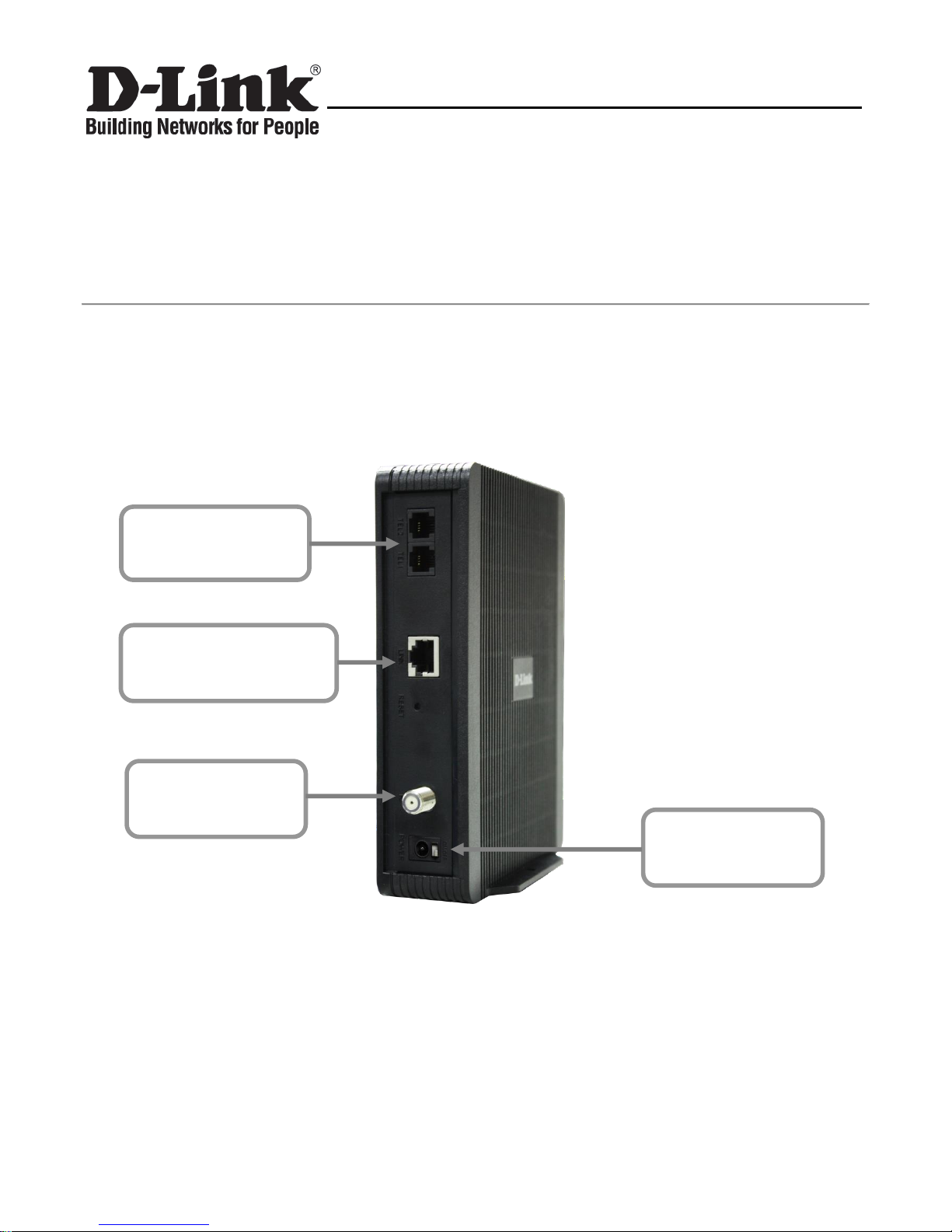
Rear Panel and Hardware Connection
This chapter describes the proper steps for connecting your cable modem. Please be sure to follow
the steps in the sequence outlined below. Failure to do so could result in improper operation or failure
of your cable modem.
Step 1: Connect a cable by feeding the F-connector on the back of the cable modem. Ensure the
center conductor of the 75 ohm coaxial cable is inserted directly into the center of the
F-connector. Secure the coaxial cable by carefully threading the outer shell of the coaxial
cable connector onto the F-connector in a clockwise direction until tight. Be careful not to
over-tighten the connector or you may damage either the connector or the cable modem.
Step2: Connect the cable modem to an IEEE 802.3 10BaseT / 802.3u 100Base-TX Network using a
RJ-45 male-terminated Ethernet cable. This cable modem equips with one Ethernet port.
Step 1 Connecting
the Coaxial Cable
Step 3 Connecting
the Telephone cord
Step 4 Connecting
the AC Adapter
Step 2 Connecting to a
Network Interface Cord
Page 2

DCM-3012G VoIP Cable Modem Quick Installation Guide
Step 3: Connect the telephone sets to TEL1 and TEL2. Use RJ-11 telephone line to connect
TEL1/TEL2 port on the cable modem and telephone socket on telephone.
Step 4: Connect the AC Adapter to the cable modem by inserting the barrel-shaped connector into the
mating power connector on the back of the cable modem. Exercise carefully to ensure the
connectors are properly aligned prior to insertion and ensure the two connectors engage
completely. The cable modem is shipped with an AC adapter. Remember to use only power
adapter that came with the cable modem. Other power adapters might have voltages that are
not correct for your particular cable modem. Using a power adapter with the wrong voltage can
damage the cable modem.
Page 3

DCM-3012G VoIP Cable Modem Quick Installation Guide
Front Panel & LEDs
There are seven Light-Emitting-Diodes (LEDs) located on the front panel top provide status
information to the user.
Page 4

DCM-3012G VoIP Cable Modem Quick Installation Guide
NAME
COLOR
MODE
STATUS
Power
Green
On
DC power connected
Off
No DC power connected
DS
Orange
Blinking
Downstream scanning
On
Downstream locked
Off
Cable interface idle
Green
On
W/DS locked
Off
W/DS disabled or CM standby
US
Orange
Blinking
Upstream Ranging
On
Upstream locked
Off
Cable interface idle
Green
On
W/US locked
Off
W/US disabled or CM standby
ONLINE
Green
Blinking
CM provisioning
On
CM on-line
Off
Cable interface idle
LINK
Orange
Blinking
Data in traffic (FE mode)
On
Ethernet device connected (FE mode)
Off
No Ethernet device connected (FE mode)
Green
Blinking
Data in traffic (GbE mode)
On
Ethernet device connected (GbE mode)
Off
No Ethernet device connected (GbE mode)
TEL 1
Green
Blinking
TEL1 provisioning or off-hook
On
TEL1 on-hook
Off
TEL1 disabled
TEL 2
Green
Blinking
TEL2 provisioning or off-hook
On
TEL2 on-hook
Off
TEL2 disabled
Page 5

DCM-3012G VoIP Cable Modem Quick Installation Guide
Technical Support
You can find software updates and user documentation/manual on the D-Link website.
Tech Support for customers within Singapore:
D-Link Technical Support over the Telephone:
Service Centre Hotline: (65) 6774 6233 [Press 1]
24x7 Technical Support Hotline: (65) 6501 4280 (StarHub Customer)
D-Link Technical Support over the Internet:
www.dlink.com.sg/support/
email:support@dlink.com.sg
This document is subject to change without notice 7MN-Ixxxxx-xxxR
 Loading...