


One H.P. Single-
Stage Dust
Collector
Dépoussiéreur à étage unique de 1 HP
Colector de polvo monoetápico de un H.P.
A15097 - 01-13-06
Copyright © 2006 Delta Machinery
AP400
10" Contractors Saw
(Model 36-978/36-979)
Instruction Manual
Manuel d’Utilisation
Manual de Instrucciones
FRANÇAIS (15) |
ESPAÑOL (27) |
|
|
www.deltamachinery.com
(800) 223-7278 - US
(800) 463-3582 - CANADA

TABLE OF CONTENTS
IMPORTANT SAFETY INSTRUCTIONS . . . . . . . . . . . . . . . . . . . . . . . . . . . . . . . . . . . . . . . . . . . . . . . . . . . . . . . . . . . 2 SAFETY GUIDELINES - DEFINITIONS . . . . . . . . . . . . . . . . . . . . . . . . . . . . . . . . . . . . . . . . . . . . . . . . . . . . . . . . . . . 3 GENERAL SAFETY RULES . . . . . . . . . . . . . . . . . . . . . . . . . . . . . . . . . . . . . . . . . . . . . . . . . . . . . . . . . . . . . . . . . . . . 4 ADDITIONAL SPECIFIC SAFETY RULES . . . . . . . . . . . . . . . . . . . . . . . . . . . . . . . . . . . . . . . . . . . . . . . . . . . . . . . . . 5 FUNCTIONAL DESCRIPTION . . . . . . . . . . . . . . . . . . . . . . . . . . . . . . . . . . . . . . . . . . . . . . . . . . . . . . . . . . . . . . . . . . 8 CARTON CONTENTS . . . . . . . . . . . . . . . . . . . . . . . . . . . . . . . . . . . . . . . . . . . . . . . . . . . . . . . . . . . . . . . . . . . . . . . . . 8 ASSEMBLY . . . . . . . . . . . . . . . . . . . . . . . . . . . . . . . . . . . . . . . . . . . . . . . . . . . . . . . . . . . . . . . . . . . . . . . . . . . . . . . . . 9 OPERATION . . . . . . . . . . . . . . . . . . . . . . . . . . . . . . . . . . . . . . . . . . . . . . . . . . . . . . . . . . . . . . . . . . . . . . . . . . . . . . . 13 TROUBLESHOOTING . . . . . . . . . . . . . . . . . . . . . . . . . . . . . . . . . . . . . . . . . . . . . . . . . . . . . . . . . . . . . . . . . . . . . . . . 14 MAINTENANCE. . . . . . . . . . . . . . . . . . . . . . . . . . . . . . . . . . . . . . . . . . . . . . . . . . . . . . . . . . . . . . . . . . . . . . . . . . . . . 14 SERVICE . . . . . . . . . . . . . . . . . . . . . . . . . . . . . . . . . . . . . . . . . . . . . . . . . . . . . . . . . . . . . . . . . . . . . . . . . . . . . . . . . . 14 ACCESSORIES . . . . . . . . . . . . . . . . . . . . . . . . . . . . . . . . . . . . . . . . . . . . . . . . . . . . . . . . . . . . . . . . . . . . . . . . . . . . . 14 WARRANTY. . . . . . . . . . . . . . . . . . . . . . . . . . . . . . . . . . . . . . . . . . . . . . . . . . . . . . . . . . . . . . . . . . . . . . . . . . . . . . . . 14 FRANÇAIS . . . . . . . . . . . . . . . . . . . . . . . . . . . . . . . . . . . . . . . . . . . . . . . . . . . . . . . . . . . . . . . . . . . . . . . . . . . . . . . . . 15 ESPAÑOL. . . . . . . . . . . . . . . . . . . . . . . . . . . . . . . . . . . . . . . . . . . . . . . . . . . . . . . . . . . . . . . . . . . . . . . . . . . . . . . . . . 27
IMPORTANT SAFETY INSTRUCTIONS
 Read and understand all warnings and operating instructions before using any tool or equipment. When using tools or equipment, basic safety precautions should always be followed to reduce the risk of personal injury. Improper operation, maintenance or modification of tools or equipment could result in serious injury and property damage. There are certain applications for which tools and equipment are designed. Delta Machinery strongly recommends that this product NOT be modified and/or used for any application other than for which it was designed.
If you have any questions relative to its application DO NOT use the product until you have written Delta Machinery and we have advised you.
Online contact form at www.deltamachinery.com
Postal Mail: Technical Service Manager
Delta Machinery
4825 Highway 45 North
Jackson, TN 38305
(IN CANADA: 125 Mural St. Suite 300, Richmond Hill, ON, L4B 1M4)
Information regarding the safe and proper operation of this tool is available from the following sources: Power Tool Institute
1300 Sumner Avenue, Cleveland, OH 44115-2851 www.powertoolinstitute.org
National Safety Council
1121 Spring Lake Drive, Itasca, IL 60143-3201
American National Standards Institute, 25 West 43rd Street, 4 floor, New York, NY 10036 www.ansi.org
ANSI 01.1Safety Requirements for Woodworking Machines, and the U.S. Department of Labor regulations www.osha.gov
SAVE THESE INSTRUCTIONS!
2

SAFETY GUIDELINES - DEFINITIONS
It is important for you to read and understand this manual. The information it contains relates to protecting YOUR SAFETY and PREVENTING PROBLEMS. The symbols below are used to help you recognize this information.
Indicates an imminently hazardous situation which, if not avoided, will result in death or serious injury.
Indicates a potentially hazardous situation which, if not avoided, could result in death or serious injury.
Indicates a potentially hazardous situation which, if not avoided, may result in minor or moderate injury.
Used without the safety alert symbol indicates potentially hazardous situation which, if not avoided, may result in property damage.
CALIFORNIA PROPOSITION 65
 Some dust created by power sanding, sawing, grinding, drilling, and other construction activities contains chemicals known to cause cancer, birth defects or other reproductive harm. Some examples of these chemicals are:
•lead from lead-based paints,
•crystalline silica from bricks and cement and other masonry products, and
•arsenic and chromium from chemically-treated lumber.
Your risk from these exposures varies, depending on how often you do this type of work. To reduce your exposure to these chemicals: work in a well ventilated area, and work with approved safety equipment, always wear NIOSH/OSHA approved, properly fitting face mask or respirator when using such tools.
3

GENERAL SAFETY RULES
 Failure to follow these rules may result in serious personal injury.
1.FOR YOUR OWN SAFETY, READ THE INSTRUCTION MANUAL BEFORE OPERATING THE MACHINE.
Learning the machine’s application, limitations, and specific hazards will greatly minimize the possibility of accidents and injury.
2.WEAR EYE AND HEARING PROTECTION. ALWAYS USE SAFETY GLASSES. Everyday eyeglasses are NOT safety glasses. USE CERTIFIED SAFETY EQUIPMENT. Eye protection equipment should comply with ANSI Z87.1 standards. Hearing equipment should comply with ANSI S3.19 standards.
3.WEAR PROPER APPAREL. Do not wear loose clothing, gloves, neckties, rings, bracelets, or other jewelry which may get caught in moving parts. Nonslip protective footwear is recommended. Wear protective hair covering to contain long hair.
4.DO NOT USE THE MACHINE IN A DANGEROUS ENVIRONMENT. The use of power tools in damp or wet locations or in rain can cause shock or electrocution. Keep your work area well-lit to prevent tripping or placing arms, hands, and fingers in danger.
5.MAINTAIN ALL TOOLS AND MACHINES IN PEAK CONDITION. Keep tools sharp and clean for best and safest performance. Follow instructions for lubricating and changing accessories. Poorly maintained tools and machines can further damage the tool or machine and/or cause injury.
6.CHECK FOR DAMAGED PARTS. Before using the machine, check for any damaged parts. Check for alignment of moving parts, binding of moving parts, breakage of parts, and any other conditions that may affect its operation. A guard or any other part that is damaged should be properly repaired or replaced with Delta or factory authorized replacement parts.
Damaged parts can cause further damage to the machine and/or injury.
7.KEEP THE WORK AREA CLEAN. Cluttered areas and benches invite accidents.
8.KEEP CHILDREN AND VISITORS AWAY. Your shop is a potentially dangerous environment. Children and visitors can be injured.
9.REDUCE THE RISK OF UNINTENTIONAL STARTING.
Make sure that the switch is in the “OFF” position before plugging in the power cord. In the event of a power failure, move the switch to the “OFF” position. An accidental start-up can cause injury. Do not touch the plug’s metal prongs when unplugging or plugging in the cord.
10.USE THE GUARDS. Check to see that all guards are in place, secured, and working correctly to prevent injury.
11.REMOVE ADJUSTING KEYS AND WRENCHES BEFORE STARTING THE MACHINE. Tools, scrap pieces, and other debris can be thrown at high speed, causing injury.
12.USE THE RIGHT MACHINE. Don’t force a machine or an attachment to do a job for which it was not designed. Damage to the machine and/or injury may result.
13.USE RECOMMENDED ACCESSORIES. The use of accessories and attachments not recommended by Delta may cause damage to the machine or injury to the user.
14.USE THE PROPER EXTENSION CORD. Make sure your extension cord is in good condition. When using an extension cord, be sure to use one heavy enough to carry the current your product will draw. An undersized cord will cause a drop in line voltage, resulting in loss of power and overheating. See the Extension Cord Chart for the correct size depending on the cord length and nameplate ampere rating. If in doubt, use the next heavier gauge. The smaller the gauge number, the heavier the cord.
15.SECURE THE WORKPIECE. Use clamps or a vise to hold the workpiece when practical. Loss of control of a workpiece can cause injury.
16.FEED THE WORKPIECE AGAINST THE DIRECTION OF THE ROTATION OF THE BLADE, CUTTER, OR ABRASIVE SURFACE. Feeding it from the other direction will cause the workpiece to be thrown out at high speed.
17.DON’T FORCE THE WORKPIECE ON THE MACHINE.
Damage to the machine and/or injury may result.
18.DON’T OVERREACH. Loss of balance can make you fall into a working machine, causing injury.
19.NEVER STAND ON THE MACHINE. Injury could occur if the tool tips, or if you accidentally contact the cutting tool.
20.NEVER LEAVE THE MACHINE RUNNING UNATTENDED. TURN THE POWER OFF. Don’t leave the machine until it comes to a complete stop. A child or visitor could be injured.
21.TURN THE MACHINE “OFF”, AND DISCONNECT THE MACHINE FROM THE POWER SOURCE before installing or removing accessories, changing cutters, adjusting or changing set-ups. When making repairs, be sure to lock the start switch in the “OFF” position. An accidental start-up can cause injury.
22.MAKE YOUR WORKSHOP CHILDPROOF WITH PADLOCKS, MASTER SWITCHES, OR BY REMOVING STARTER KEYS. The accidental start-up of a machine by a child or visitor could cause injury.
23. STAY ALERT, WATCH WHAT YOU ARE DOING,
AND USE COMMON SENSE. DO NOT USE THE MACHINE WHEN YOU ARE TIRED OR UNDER THE INFLUENCE OF DRUGS, ALCOHOL, OR MEDICATION. A moment of inattention while operating power tools may result in injury.
24.  U S E O F T H I S T O O L C A N
GENERATE AND DISBURSE DUST OR OTHER AIRBORNE PARTICLES, INCLUDING WOOD DUST, CRYSTALLINE SILICA DUST AND ASBESTOS DUST.
Direct particles away from face and body. Always operate tool in well ventilated area and provide for proper dust removal. Use dust collection system wherever possible. Exposure to the dust may cause serious and permanent respiratory or other injury, including silicosis (a serious lung disease), cancer, and death. Avoid breathing the dust, and avoid prolonged contact with dust. Allowing dust to get into your mouth or eyes, or lay on your skin may promote absorption of harmful material. Always use properly fitting NIOSH/ OSHA approved respiratory protection appropriate for the dust exposure, and wash exposed areas with soap and water.
4

ADDITIONAL SPECIFIC SAFETY RULES
 Failure to follow these rules may result in serious personal injury.
DO NOT USE THIS UNIT TO FILTER METAL DUST. Combining wood and metal dust can create an explosion or fire hazard. This unit is intended to filter non-explosive atmospheres only.
DO NOT USE THIS UNIT TO DISSIPATE FUMES OR SMOKE. Explosions or fire can result. This dust collector is intended for use where only dry airborne dust is present. Its use should be limited to nonexplosive, non-metallic atmospheres.
1.DO NOT OPERATE THIS UNIT UNTIL IT IS COMPLETE-LY ASSEMBLED AND INSTALLED ACCORDING TO THE INSTRUCTIONS. A unit incorrectly assembled can cause injury.
2.OBTAIN ADVICE FROM YOUR SUPERVISOR, IN-STRUCTOR, OR ANOTHER QUALIFIED PERSON if you are not thoroughly familiar with the operation of this unit. Knowledge is safety
3.FOLLOW ALL WIRING CODES and recommended electrical connections to prevent electrical shock or electrocution.
4.DO NOT PULL THIS UNIT BY THE POWER CORD. Do not allow the power cord to come in contact with sharp instruments or edges, hot surfaces, or oil or grease. Do not place any weight on top of the power cord. A damaged power cord can cause electrical shock or electrocution.
5.SUPPORT THIS UNIT OR SECURELY CLAMP IT TO THE WORK SURFACE WHEN IT IS USED IN A PORTABLE APPLICATION to eliminate potential injury and/or damage from falling.
6.ENSURE THAT THE INTAKE AND EXHAUST AREAS ARE CLEAR PRIOR TO STARTING THE UNIT. Clogged intakes or exhausts can cause an explosion and/or fire.
7.DO NOT USE THE DUST COLLECTOR to pick up flammable liquids such as gasoline. Do not use the dust collector near flammable or combustible liquids. Explosion and/or fire can occur.
8.KEEP ARMS, HANDS, AND FINGERS AWAY FROM THE FAN. Avoid all exposure to rotating parts to prevent injury.
9.DO NOT OPERATE THIS UNIT WITHOUT THE DUST COLLECTION BAG IN PLACE AND PROPERLY SECURED. Sawdust and other debris can provide the potential for fire and/or explosion and can also cause inhalation problems.
10.INSPECT THE DUST BAG FOR CUTS, RIPS, OR TEARS. Replace damaged bags or vacuum hoses. Sawdust and other debris can provide the potential for fire and/or explosion and can also cause inhalation problems.
11.ALWAYS USE THE INTAKE CAPS TO COVER UNUSED DUST PORTS. Debris can cause damage to the unit and injury.
12.DO NOT ATTEMPT TO REMOVE OR REPLACE the dust collection bag(s) while the unit is connected to the power source. Exposed fan blades can cause severe injuries.
13.MAINTAIN THE UNIT IN TOP CONDITION.
Clogged filters can increase the potential for fire or explosion. Follow all instructions for changing and cleaning filters.
14.STORE THIS UNIT IN A LOCATION that eliminates
the potential for damage to the power cord. A damaged power cord can cause shock or electrocution. Safely store power cord on the unit to eliminate tripping hazards.
15.TURN THE UNIT “OFF” AND DISCONNECT THE UNIT from the power source before installing or removing accessories, before adjusting or changing set-ups, or when making repairs. An accidental start-up can cause serious injury.
16.TURN THE UNIT “OFF”, disconnect the unit from the power source, and clean the table/work area before leaving the area.
SAVE THESE INSTRUCTIONS.
Refer to them often
and use them to instruct others.
5
POWER CONNECTIONS
A separate electrical circuit should be used for your machines. This circuit should not be less than #12 wire and should be protected with a 20 Amp time lag fuse. If an extension cord is used, use only 3-wire extension cords which have 3-prong grounding type plugs and matching receptacle which will accept the machine’s plug. Before connecting the machine to the power line, make sure the switch (s) is in the “OFF” position and be sure that the electric current is of the same characteristics as indicated on the machine. All line connections should make good contact. Running on low voltage will damage the machine.
 Do not expose the machine to rain or operate the machine in damp locations.
MOTOR SPECIFICATIONS
Your machine is wired for 120/240 volts 60 HZ alternating current. Before connecting the machine to the power source, make sure the switch is in the “OFF” position.
GROUNDING INSTRUCTIONS
 This machine must be grounded while in use to protect the operator from electric shock.
1.All grounded, cord-connected machines:
In the event of a malfunction or breakdown, grounding provides a path of least resistance for electric current to reduce the risk of electric shock. This machine is equipped with an electric cord having an equipment-grounding conductor and a grounding plug. The plug must be plugged into a matching outlet that is properly installed and grounded in accordance with all local codes and ordinances.
Do not modify the plug provided - if it will not fit the outlet, have the proper outlet installed by a qualified electrician.
Improper connection of the equipment-grounding conduc-tor can result in risk of electric shock. The conductor with insulation having an outer surface that is green with or without yellow stripes is the equipment-grounding conductor. If repair or replacement of the electric cord or plug is necessary, do not connect the equipment-grounding conductor to a live terminal.
Check with a qualified electrician or service personnel if the grounding instructions are not completely understood, or if in doubt as to whether the machine is properly grounded.
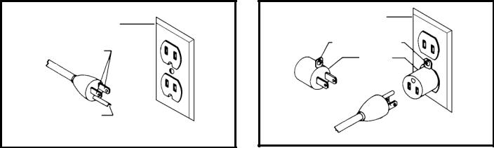
Use only 3-wire extension cords that have 3-prong grounding type plugs and matching 3-conductor receptacles that accept the machine’s plug, as shown in Fig. A.
Repair or replace damaged or worn cord immediately.
2.Grounded, cord-connected machines intended for use on a supply circuit having a nominal rating less than 150 volts:
If the machine is intended for use on a circuit that has an outlet that looks like the one illustrated in Fig. A, the machine will have a grounding plug that looks like the plug illustrated in Fig. A. A temporary adapter, which looks like the adapter illustrated in Fig. B, may be used to connect this plug to a matching 2-conductor receptacle as shown in Fig. B if a properly grounded outlet is not available. The temporary adapter should be used only until a properly grounded outlet can be installed by a qualified electrician. The green-colored rigid ear, lug, and the like, extending from the adapter must be connected to a permanent ground such as a properly grounded outlet box. Whenever the adapter is used, it must be held in place with a metal screw.
NOTE: In Canada, the use of a temporary adapter is not permitted by the Canadian Electric Code.
 In all cases, make certain that the receptacle in question is properly grounded. If you are not sure, have a qualified electrician check the receptacle.
|
GROUNDED OUTLET BOX |
||
GROUNDED OUTLET BOX |
|
|
|
CURRENT |
GROUNDING MEANS |
||
|
|
|
|
CARRYING |
|
|
|
|
ADAPTER |
|
|
PRONGS |
|
|
|
|
|
|
|
|
|
|
|
GROUNDING BLADE
IS LONGEST OF THE 3 BLADES
Fig. A |
Fig. B |
6
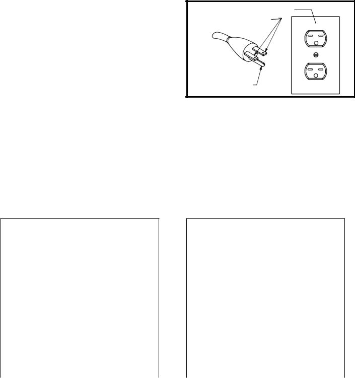
3.240 VOLT SINGLE PHASE OPERATION
The motor supplied with your machine is a dual voltage, 120/240 volt motor. It is shipped ready- to-run for 120 volt operation. However, it can be converted for 240 volt operation.
A qualified electrician should do the conversion, or the machine can be taken to an Authorized Delta Service Center. When completed, the machine must conform to the National Electric Code and all local codes and ordinances.
The machine is converted by re-wiring the motor for 240 volts, installing a 240 volt plug on the power supply cord and replacing the switch with one that is rated for 240 volt operation.
Be sure the 240 volt plug is only used in an outlet having the same configuration as the plug illustrated in Fig. C. No adapter should be used with the 240 volt plug.
GROUNDED OUTLET BOX
CURRENT
CARRYING
PRONGS
GROUNDING BLADE
IS LONGEST OF THE 3 BLADES
Fig. C
 In all cases, make certain that the receptacle in question is properly grounded. If you are not sure, have a qualified electrician check the receptacle.
EXTENSION CORDS
 Use proper extension cords. Make sure your extension cord is in good condition and is a 3- wire extension cord which has a 3-prong grounding type plug and matching receptacle which will accept the machine’s plug. When using an extension cord, be sure to use one heavy enough to carry the current of the machine. An undersized cord will cause a drop in line voltage, resulting in loss of power and overheating. Fig. D- 1 or D-2, shows the correct gauge to use depending on the cord length. If in doubt, use the next heavier gauge. The smaller the gauge number, the heavier the cord.
MINIMUM GAUGE EXTENSION CORD
RECOMMENDED SIZES FOR USE WITH STATIONARY ELECTRIC MACHINES
|
|
Total |
|
Ampere |
|
Length of |
|
|
Cord in |
Gauge of Extension |
|
|
|
||
Rating |
Volts |
Feet |
Cord |
0-6 |
120 |
up to 25 |
18 AWG |
0-6 |
120 |
25-50 |
16 AWG |
0-6 |
120 |
50-100 |
16 AWG |
0-6 |
120 |
100-150 |
14 AWG |
6-10 |
120 |
up to 25 |
18 AWG |
6-10 |
120 |
25-50 |
16 AWG |
6-10 |
120 |
50-100 |
14 AWG |
6-10 |
120 |
100-150 |
12 AWG |
10-12 |
120 |
up to 25 |
16 AWG |
10-12 |
120 |
25-50 |
16 AWG |
10-12 |
120 |
50-100 |
14 AWG |
10-12 |
120 |
100-150 |
12 AWG |
12-16 |
120 |
up to 25 |
14 AWG |
12-16 |
120 |
25-50 |
12 AWG |
12-16 |
120 |
GREATER THAN 50 FEET NOT RECOMMENDED |
|
|
|
Fig. D-1 |
|
MINIMUM GAUGE EXTENSION CORD
RECOMMENDED SIZES FOR USE WITH STATIONARY ELECTRIC MACHINES
|
|
Total |
|
|
Ampere |
|
Length of |
|
|
|
Cord in |
|
Gauge of Extension |
|
|
|
|
||
Rating |
Volts |
Feet |
|
Cord |
0-6 |
240 |
up to 50 |
|
18 AWG |
0-6 |
240 |
50-100 |
|
16 AWG |
0-6 |
240 |
100-200 |
|
16 AWG |
0-6 |
240 |
200-300 |
|
14 AWG |
6-10 |
240 |
up to 50 |
|
18 AWG |
6-10 |
240 |
50-100 |
|
16 AWG |
6-10 |
240 |
100-200 |
|
14 AWG |
6-10 |
240 |
200-300 |
|
12 AWG |
10-12 |
240 |
up to 50 |
|
16 AWG |
10-12 |
240 |
50-100 |
|
16 AWG |
10-12 |
240 |
100-200 |
|
14 AWG |
10-12 |
240 |
200-300 |
|
12 AWG |
12-16 |
240 |
up to 50 |
|
14 AWG |
12-16 |
240 |
50-100 |
|
12 AWG |
12-16 |
240 |
GREATER THAN 50 FEET NOT RECOMMENDED |
||
|
|
Fig. D-2 |
|
|
7
FUNCTIONAL DESCRIPTION
FOREWORD
The Delta AP400 will connect to woodworking machines that accept a 4" diameter hose. The Model AP400 comes with two 30 micron collection bags, and a 4" x 5 ft. collection hose.
NOTICE: The photo on the manual cover illustrates the current production model. All other illustrations contained in the manual are representative only and may not depict the actual labeling or accessories included. These are intended to illustrate technique only.
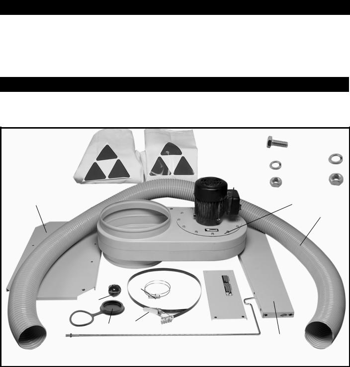
CARTON CONTENTS
5 |
|
|
|
6 |
12 |
|
|
|
|
|
16 |
|
|
|
|
|
|
|
|
|
|
|
|
|
|
|
|
||||
|
|
|
13 |
|
|
|
|
|
|
|
|
|
|||
|
|
|
|
|
|
|
|
|
|
|
|
||||
|
|
|
|
|
|
|
|
|
|
|
|
||||
|
|
|
|
|
|
|
|
|
|
17 |
|
|
|
|
|
|
|
|
|
|
|
|
|
|
|
|
|
|
|
||
2 |
|
|
|
|
14 |
|
|
|
|
|
|
|
|
|
|
|
|
|
|
|
|
|
|
|
|
|
|
|
|||
|
|
|
|
|
|
|
|
|
|
|
|
|
|
||
|
|
|
|
|
|
|
|
|
|
|
|
|
|
||
|
|
|
|
|
|
|
|
|
|
|
|
|
|
|
|
|
|
|
|
|
|
|
|
|
|
|
|
|
|
|
|
|
|
|
|
1 |
|
|
|
|
|||||||
10
|
11 |
|
|
|
3 |
|
|
|
|
15 |
7 |
|
|
|
|
|
|
||
8 |
|
|
||
|
|
|
||
|
|
|
4 |
|
|
|
|||
|
|
|
|
|
|
9 |
|||
|
|
Fig. 2 |
|
1. |
Motor and blower assembly |
10. |
Hose |
2. |
Base |
11. |
Hose clamp (2) |
3. |
Wheel casters (4) |
12. |
5/16-18x3/4" Hex head screw (12) |
4. |
Side support (2) |
13. |
5/16 Lockwasher (12) |
5. |
Upper bag (bag with loop see Fig. 14) |
14. |
5/16-18 Hex nut (9) |
6. |
Lower bag |
15. |
Intake cap |
7. |
Filter bag clamp (2) |
16. |
3/8 Lockwashers (4) for casters |
8. |
Support |
17. |
3/8-16 Hex nuts (4) for casters |
9. |
Filter bag hanger (w/ hex nut) |
|
|
8
UNPACKING AND CLEANING
Carefully unpack the machine and all loose items from the shipping container(s). Remove the rust-preventative oil from unpainted surfaces using a soft cloth moistened with mineral spirits, paint thinner or denatured alcohol.
Do not use highly volatile solvents such as gasoline, naphtha, acetone or lacquer thinner for cleaning your machine.
After cleaning, cover the unpainted surfaces with a good quality household floor paste wax.
ASSEMBLY
 For your own safety, do not connect the machine to the power source until the machine is completely assembled and you read and understand the entire instruction manual.
ASSEMBLY TOOLS REQUIRED
1/2” and 9/16” Wrench, Open-End or Socket
ASSEMBLY TIME ESTIMATE
Assembly for this machine takes approximately 1-2 hours.
CASTERS
1.Locate the bag of hardware with the four 3/8 hex nuts and four 3/8 lockwashers for the four casters.
2. |
For each wheel, |
insert bolt from caster through the |
A |
|
holes (A) Fig. 3 |
in the base of the dust collector |
|
|
(three are not shown). |
|
|
3. |
Place a 3/8 lockwasher (A) Fig. 4 onto each bolt. |
|
|
Fig. 3 |
|||
4.Thread 3/8 hex nut (B) Fig. 4 onto each of the four bolts and tighten securely.
B
A
Fig. 4
9
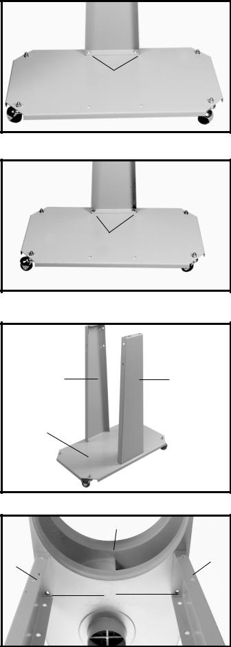
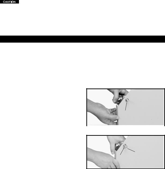
SIDE SUPPORTS
1.Place the dust collector base (A) Fig. 5, in an upright position as shown.
2.Align the two holes in the wider end of the side support (B) Fig. 5 with the two holes (C) in the base.
3.Insert a 5/16-18x3/4" hex head screw (A) Fig. 6 thru each hole in the side support and base.
4.Place a 5/16" lockwasher onto the hex head screw.
5.Thread a 5/16-18 hex nut onto the hex head screw and tighten securely.
6.Repeat this process for the remaining side support.
7.Fig. 7 shows both side supports (A) attached to the base (B).
ATTACHING MOTOR AND BLOWER ASSEMBLY TO FRAME
1.Place motor assembly and base assembly on their side.
2.Align the four holes, two shown at (C), on the top of the side supports (A) Fig. 8, with the four holes in the motor assembly (B).
3.Place a 5/16" lockwasher onto a 5/16-18x3/4" hex head screw and insert the bolt thru the side support and thread bolt into the tapped hole in the motor assembly and tighten securely.
4.Repeat this process for the three remaining holes.
5.Fig. 9 shows the motor and blower assembly attached to the side supports.
 A
A
B 
C
Fig. 5
A
Fig. 6
A A
B
Fig. 7
B
A
A
C
Fig. 8
10
SUPPORT
1.Place the support (A) Fig. 10 inside the two side supports (B). NOTE: MAKE SURE SUPPORT IS
ATTACHED TO THE SIDE SUPPORTS CLOSEST TO THE MOTOR.
2.Align the four holes in the support with the four holes in the side supports as shown in Fig. 10.
3.Insert a 5/16-18x3/4" hex head screw (A) Fig. 11, thru the side supports and the support.
4.Place a 5/16" lockwasher on the hex head screw.
5.Thread a 5/16-18 hex nut on the hex head screw and tighten securely.
6.Repeat this process for the three remaining holes for attaching the support.
7.Fig. 12 shows the support attached to the side supports.
Fig. 9
B |
A |
B |
|
||
|
Fig. 10 |
|
A
Fig. 11
Fig. 12
11
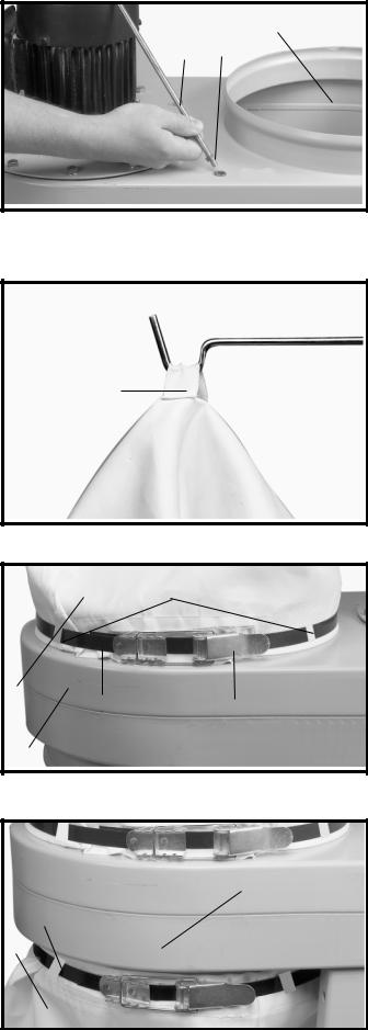
FILTER AND DUST COLLECTION BAGS TO DRUM
1.Thread a 5/16-18 hex nut (A) Fig. 13, onto the end of bag support rod (B). Thread rod into hole (E) and tighten nut (A) against motor assembly to hold support rod (B) upright. Height of support rod can be adjusted after the filter bag is in place. The hook in the support rod (B) should be positioned over the drum. This can be accomplished by rotating the support rod until the hook is positioned over the drum (C) Fig. 13.
2.Hook the loop on the top of filter bag (F) Fig. 14, onto the end of support rod (B).
3.Position open end of filter bag (F) Fig. 15, over the lip of drum (G). NOTE: It may be necessary to adjust the height of the drum support rod at this time. If adjustment is necessary, loosen nut (A) Fig. 13, and rotate support rod (B) as needed to obtain proper rod height to support filter bag (F). Tighten nut (A) Fig. 13.
4.Place locking band (H) Fig. 15 around the filter bag (F), through filter bag loops (L), and fasten filter bag to drum by locking clamp (J) as shown in Fig. 15. IMPORTANT: Make certain band (H) is positioned in the channel of drum (G) before locking clamp (J).
5.Place the remaining locking band (H) Fig. 16, around the dust collection bag (K) and collection bag loops
(M).Position open end of bag over the lip of drum
(G)and fasten with locking clamp (J). NOTE: Make certain locking band (H) is positioned in the channel of drum before locking clamp (J).
C
B A
E
Fig. 13
B
F
Fig. 14
|
L |
F |
|
H |
J |
G |
|
Fig. 15
G
M
H
K |
J |
M |
||
|
|
|
|
|
|
|
|
|
|
|
|
|
|
|
|
|
|
|
|
Fig. 16
12
 Loading...