


AM-FM STEREO/DAB TUNER
TU-1800DAB
OPERATING INSTRUCTIONS
2 SAFETY PRECAUTIONS
CAUTION
RISK OF ELECTRIC SHOCK
DO NOT OPEN
CAUTION:
TO REDUCE THE RISK OF ELECTRIC SHOCK, DO NOT REMOVE COVER (OR BACK). NO USER-SERVICEABLE PARTS INSIDE. REFER SERVICING TO QUALIFIED SERVICE PERSONNEL.
The lightning flash with arrowhead symbol, within an equilateral triangle, is intended to alert the user to the presence of uninsulated “dangerous voltage” within the product’s enclosure that may be of sufficient magnitude to constitute a risk of electric shock to persons.
The exclamation point within an equilateral triangle is intended to alert the user to the presence of important operating and maintenance (servicing) instructions in the literature accompanying the appliance.
WARNING:
TO REDUCE THE RISK OF FIRE OR ELECTRIC SHOCK, DO NOT EXPOSE THIS APPLIANCE TO RAIN OR MOISTURE.
•DECLARATION OF CONFORMITY
We declare under our sole responsibility that this product, to which this declaration relates, is in conformity with the following standards: EN60065, EN55013, EN55020, EN61000-3-2 and EN61000-3-3. Following the provisions of 73/23/EEC, 89/336/EEC and 93/68/EEC Directive.
A NOTE ABOUT RECYCLING:
This product’s packaging materials are recyclable and can be reused. Please dispose of any materials in accordance with the local recycling regulations.
When discarding the unit, comply with local rules or regulations.
Batteries should never be thrown away or incinerated but disposed of in accordance with the local regulations concerning chemical waste.
This product and the accessories packed together constitute the applicable product according to the WEEE directive except batteries.
Whenever the power switch is in the STANDBY state, the apparatus is still connected on AC line voltage.
Please be sure to turn off the power switch or unplug the cord when you leave home for, say, a vacation.
CAUTION:
To completely disconnect this product from the mains, disconnect the plug from the wall socket outlet.
When setting up this product, make sure that the AC outlet you are using is easily acceptable.
2 NOTE ON USE
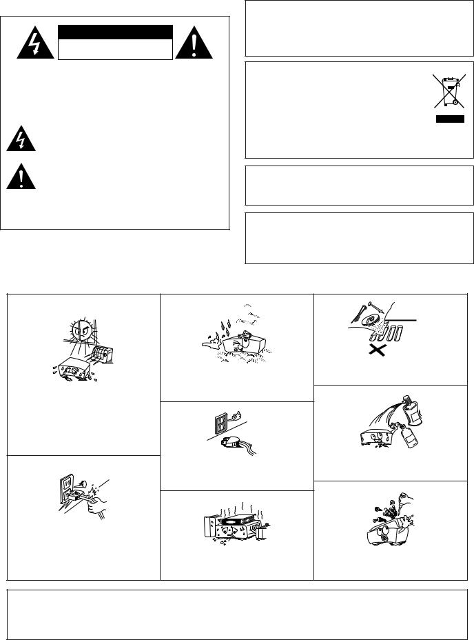
•Avoid high temperatures.
Allow for sufficient heat dispersion when installed in a rack.
•Handle the power cord carefully.
Hold the plug when unplugging the cord.
•Keep the apparatus free from moisture, water, and dust.
•Unplug the power cord when not using the set for long periods of time.
*(For apparatuses with ventilation holes)
•Do not obstruct the ventilation holes.
• Do not let foreign objects into the apparatus.
•Do not let insecticides, benzene, and thinner come in contact with the set.
•Never disassemble or modify the apparatus in any way.
CAUTION:
•Minimum distances around the apparatus for sufficient ventilation.
•The ventilation should not be impeded by covering the ventilation openings with items, such as newspapers, table-cloths, curtains, etc..
•No naked flame sources, such as lighted candles, should be placed on the apparatus.
•Attention should be drawn to the environmental aspects of battery disposal.
•The use of apparatus in tropical and/or moderate climates.
2
Getting Started
Contents |
|
Getting Started |
|
Accessories ................................................................................... |
3 |
Before using.................................................................................. |
3 |
Cautions on installation............................................................ |
4 |
Inserting the batteries ............................................................... |
4 |
Operating range of the remote control unit....................... |
5 |
Part names and functions |
|
Front panel ..................................................................................... |
6 |
Remote control unit ....................................................................... |
7 |
Connections |
|
Connecting the antenna terminals ............................................... |
8 |
Cable indications ............................................................................ |
9 |
Connecting the amplifier ............................................................... |
9 |
Connecting the power supply cord and RDI................................ |
9 |
Operation |
|
Listening to FM/AM |
|
FM Auto preset memory ............................................................. |
10 |
Auto tuning (FM/AM)................................................................... |
11 |
Manual tuning (FM/AM)............................................................... |
11 |
Preset stations (FM/AM) ............................................................. |
12 |
Recalling preset stations (FM/AM) .............................................. |
13 |
RDS (Radio Data System) ............................................................ |
13 |
RDS search .................................................................................. |
14 |
PTY search ................................................................................... |
15 |
TP search ..................................................................................... |
15 |
RT (Radio Text) ............................................................................. |
16 |
Switching RDS information display.............................................. |
16 |
Registering station names (FM/AM only) .................................... |
17 |
Listening to DAB broadcasts |
|
About DAB (Digital Audio Broadcasting) ...................................... |
18 |
Tuning in DAB (Digital Audio Broadcasting) broadcasts............... |
19 |
Preset stations ............................................................................. |
20 |
Recalling preset stations .............................................................. |
20 |
Search mode |
|
Sorted list search mode ............................................................... |
20 |
Preset search mode ..................................................................... |
21 |
Tuning aid ..................................................................................... |
21 |
Sort mode (Sorting components) |
|
Alphanumeric ............................................................................... |
22 |
S. component............................................................................... |
22 |
PTY ............................................................................................... |
23 |
Switching the DAB information display ....................................... |
23 |
DRC (Dynamic Range Control)..................................................... |
24 |
Last function memory .................................................................. |
24 |
Initialization of the microprocessor .............................................. |
24 |
Troubleshooting ........................................................................ |
25 |
Specifications............................................................................. |
26 |
DAB frequency table ................................................................ |
27 |
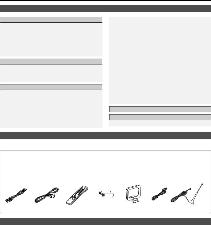
Accessories
• Check that the following parts are included in addition to the main unit:
q Operating instructions .................................................. |
1 |
w Service station list......................................................... |
1 |
e Pin-plug cable................................................................ |
1 |
r Power supply cord ........................................................ |
1 |
t Remote control unit (RC-1013) ..................................... |
1 |
y R03/AAA batteries ........................................................ |
2 |
u AM loop antenna .......................................................... |
1 |
i FM indoor antenna........................................................ |
1 |
o DAB indoor antenna...................................................... |
1 |
e |
r |
t |
y |
u |
i |
o |
Before using
As this product is provided with an immense array of features, we recommend that before you begin hookup and operation that you review the contents of this manual before proceeding.
Pay attention to the following before using this unit:
•Moving the set
To prevent short circuits or damaged wires in the connection cords, always unplug the power supply cord and disconnect the connection cords between all other audio components when moving the set.
•Before turning the Power ON/STANDBY operation switch on
Check once again that all connections are proper and that there are not problems with the connection cords.
Always set the power switch to the standby position before connecting and disconnecting connection cords.
•Store these instructions in a safe place
After reading, store these instructions along with the warranty in a safe place.
•Note that the illustrations in these instructions may differ from the actual set for explanation purposes.
3
Getting Started
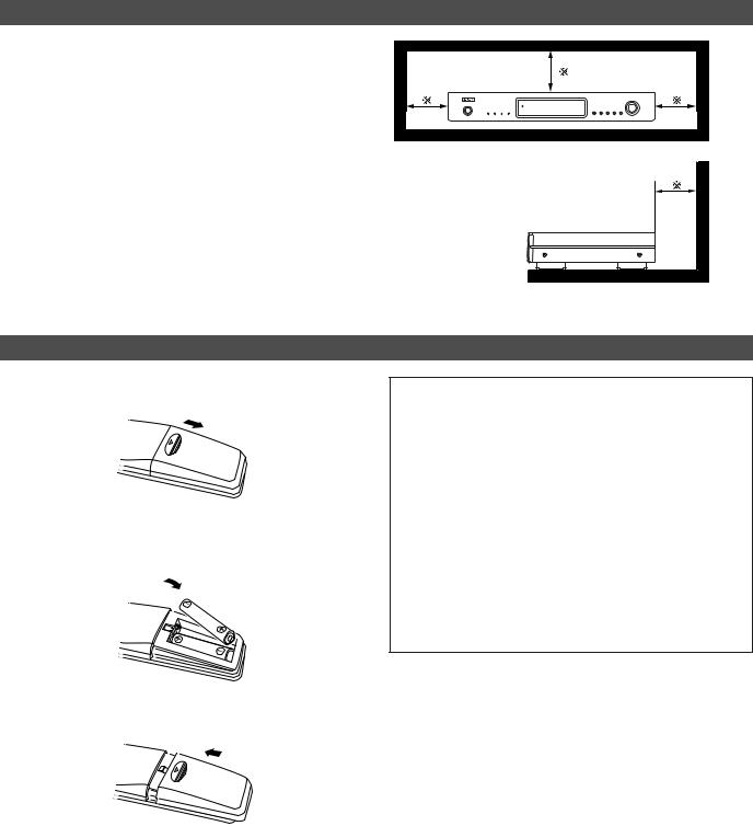
Cautions on installation
Noise or disturbance of the picture may be generated if this unit or any other electronic equipment using microprocessors is used near a tuner or TV.
If this happens, take the following steps:
•Install this unit as far as possible from the tuner or TV.
•Set the antenna wires from the tuner or TV away from this unit’s power supply cord and input/output connection cables.
•Noise or disturbance tends to occur particularly when using indoor antennas or 300 Ω/ohms feeder wires.
We recommend using outdoor antennas and 75 Ω/ohms coaxial cables.
Note:
For heat dispersal, do not install this equipment in a confined space such as a book case or similar unit.
Note |
Wall |
Inserting the batteries
q Remove the remote control unit’s rear cover.
wSet two R03/AAA batteries in the battery compartment in the indicated direction.
Notes on batteries:
•Replace the batteries with new ones if the set does not operate even when the remote control unit is operated nearby the set. (The included battery is only for verifying operation.)
•When inserting the batteries, be sure to do so in the proper direction, following the “<” and “>” marks in the battery compartment.
•To prevent damage or leakage of battery fluid:
•Do not use a new battery together with an old one.
•Do not use two different types of batteries.
•Do not short-circuit, disassemble, heat or dispose of batteries in flames.
•If the battery fluid should leak, carefully wipe the fluid off the inside of the battery compartment and insert new batteries.
•When replacing the batteries, have the new batteries ready and insert them as quickly as possible.
e Put the rear cover back on.
4
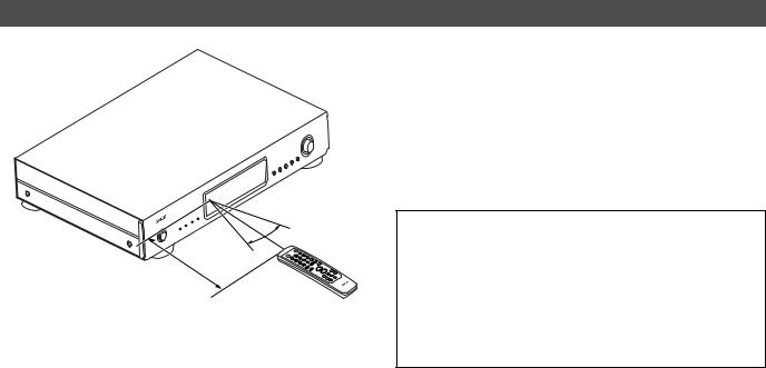
Operating range of the remote control unit
 30° 30°
Approx. 7 m
Getting Started
•Point the remote control unit at the remote sensor on the main unit as shown on the diagram.
•The remote control unit can be used from a straight distance of approximately 7 meters from the main unit, but this distance will be shorter if there are obstacles in the way or if the remote control unit is not pointed directly at the remote sensor.
•The remote control unit can be operated at a horizontal angle of up to 30 degrees with respect to the remote sensor.
NOTE:
•It may be difficult to operate the remote control unit if the remote sensor is exposed to direct sunlight or strong artificial light.
•Do not press buttons on the main unit and remote control unit simultaneously. Doing so may result in malfunction.
•Neon signs or other devices emitting pulse-type noise nearby may result in malfunction, so keep the set as far away from such devices as possible.
5
Getting Started
Part names and functions
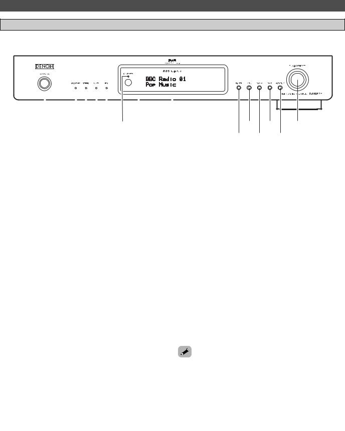
Front panel
• For details on the functions of these parts, refer to the pages given in parenthesis (  page 10 ~ 24).
|
|
|
|
|
|
|
|
|
|
|
|
|
|
|
|
|
|
|
|
|
|
|
|
|
|
|
|
|
|
|
|
|
|
|
|
|
|
|
|
|
|
|
|
|
|
|
|
|
|
|
|
w |
r |
y |
|
i |
|||
|
q |
||||||||||
|
|
e t |
u |
||||||||
|
|
|
|
|
|||||||
|
!0 !2 |
!4 |
o |
!1 !3 |
|
q Power ON/STANDBY operation switch
The unit works 2 ~ 3 seconds after this switch is turned on. Whenever the Power ON/STANDBY operation switch is in the STANDBY state, the apparatus is still connected on AC line voltage.
Please be sure to unplug the cord when you leave home for, say, a vacation.
w SECONDARY indicator
Indicates when a secondary service is available ( page 19).
e STEREO indicator
This lights when receiving stereo broadcasts. It remains off when receiving FM monaural and AM broadcasts.
r TUNED indicator
This lights when a station is properly tuned in.
t RDS indicator
This lights when receiving RDS broadcasts, and flashes during the RDS search.
y ON/STANDBY indicator
This lights when the units status is on and stand by.
u Remote control sensor
This sensor receives the infrared light transmitted from the wireless remote control unit.
For remote control, point the wireless remote control unit to the sensor.
Some of the functions can be operated with the remote control unit (RC-1013).
i Display
o DIMMER button
The display’s brightness switches (in three levels) each time this button is pressed.
!0MENU button
This button to enter/exit menu mode.
The unit times out if no operation is performed for about 5 seconds after the menu mode is set.
!1DISPLAY button
This button is used to select the display mode (  page 13, 16, 23).
!2BAND button
Selects DAB, FM or MW (AM).
!3AUTO TUNE button
Press to active auto location of all available DAB services. Press once for UK service or hold for longer than 2 seconds to activate an inter national search.
!4TUNING/PRESET knob
Each pass of this knob toggles the operation mode of the TUNING / PRESET knob.
This knob is used in conjunction with the TUNING/PRESET knob.
In the tuning mode the reception frequency is tuned up or down. Turning the control in the clockwise direction tunes the frequency up. Tuning the control in the counterclockwise direction tunes the reception frequency down.
In the preset mode the selection of the preset channel is moved up or down. The auto tuning operation cannot be used when in this mode.
When writing station names, use this control to select the letters (  page 17)
MEMO
the Power ON/STANDBY operation switch is in STANDBY position, the unit is still connected on AC line
.
be sure to unplug the cord when you leave home for, a vacation.
may be generated if a near-by television set is on MW (AM), FM, DAB broadcasting reception. The tuner be used as far away from a television as possible.
period of memory back-up is about a month under temperature.
6
Getting Started
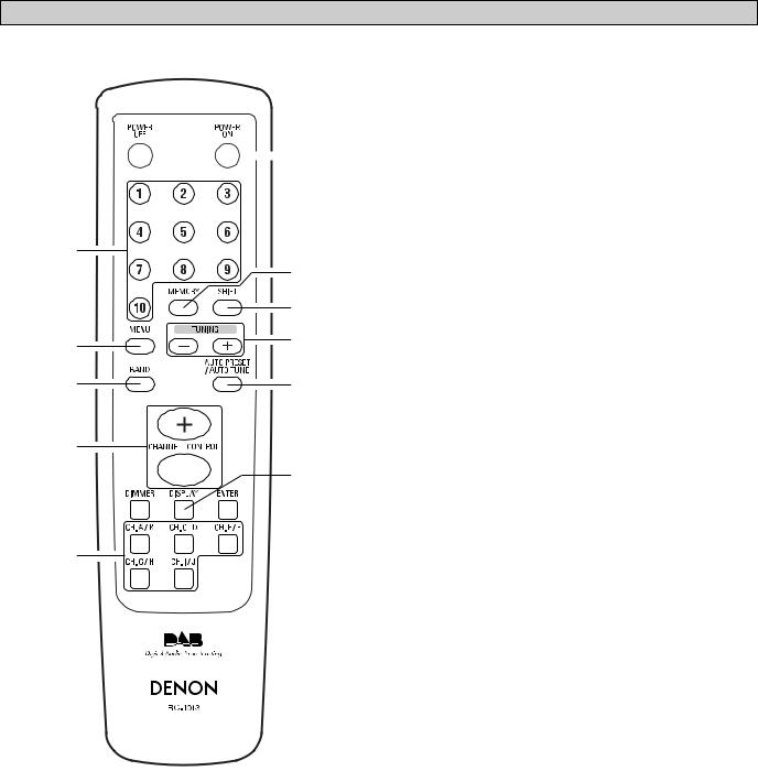
Remote control unit
• For details on the functions of these parts, refer to the pages given in parenthesis (  page 10 ~ 24).
q
 !4
!4
w
|
!3 |
|
!2 |
e |
!1 |
|
|
r |
!0 |
t

 o y
o y
 i
i
u
q POWER OFF button
Press this button to switch from the operating mode to the standby mode.
w Preset channel buttons (1 ~ 10)
Use these when presenting and recalling stations. Also use these with the SHIFT ,MEMORY BLOCK button to use a total of 200 preset channels (FM/AM 100 , DAB 100), A (1 ~ 10), B (1 ~ 10), ... J (1 ~ 10).
e MENU button
This button to enter/exit menu mode.
r BAND button
Selects DAB, FM or MW (AM).
t CHANNEL/CONTROL button
This button is used to select radio presets or select stations and menu options.
y DIMMER button
The display’s brightness switches (in three levels) each time this button is pressed.
u Preset channel range buttons (CH A/B, C/D, E/F, G/H, I/J)
Use these buttons to switch the preset channel’s shift mode directly.
i ENTER button
This button is used to set the menu.
o DISPLAY button
This button is used to select the display mode (  page 13, 16, 23).
!0AUTO PRESET/AUTO TUNE button
Press this button in the DAB mode to perform a local scan (UK band III). (UK stations are in the range 11B ~ 12D.) When the button is held in, the full scan operation (Full band and L-band) is conducted.
When pressed in the FM mode, receivable FM stations are automatically stored in the preset memory in order starting from preset channel A1.
!1TUNING buttons
Use these to change the received frequency to a higher frequency (+) or a lower frequency (–).
!2SHIFT button
Use this button to select the memory blocks, A (1 ~ 10), B (1 ~ 10), ... J (1 ~ 10).
!3MEMORY button
Frequencies and station names can be stored in the memory. When this button is pressed, the “MEMO” and “CH” indicator on the display flashes for 10 seconds. Use the SHIFT button and the Preset channel buttons during this time to designate the desired preset channel.
!4POWER ON button
Press this button to switch from the standby mode to the operating mode.
7
Connections
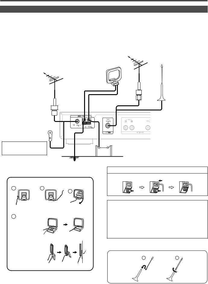
Connecting the antenna terminals
2Connecting an DAB outdoor antenna
•If good reception cannot be achieved with the included DAB indoor antenna, use an DAB outdoor antenna. Connect an F male type connector to the coaxial cable and connect the antenna to the DAB COAX 75 Ω/ohms terminal.
2Installing the DAB indoor antenna q DAB station reception (  page 18).
w Use “Tuning aid” to set position at which reception sensitivity is optimum (  page 21).
AM loop antenna |
DAB outdoor antenna |
|
|
(Supplied) |
|
FM outdoor antenna
DAB indoor antenna (Supplied)
Direction of broadcasting station
75 Ω/ohms COAXIAL cable
FM indoor antenna (Supplied)
Use tape or a pin to fasten the tip of the antenna to the wall, a rack, etc.
Ground |
AM outdoor antenna |
2 AM loop antenna assembly
1 |
2 |
Remove the vinyl tie and take out the connection line.
Connect to the AM antenna terminals.
3
Bend in the reverse direction.
4
a. With the antenna on top any stable surface.
Mount
b. With the antenna attached to a wall.
Connection of AM antennas
q Push the lever. w Insert the conductor. e Return the lever.
NOTE:
•Do not connect two FM antennas simultaneously.
•Even if an external AM antenna is used, do not disconnect the AM loop antenna.
•Make sure AM loop antenna lead terminals do not touch metal parts of the panel.
•There is a magnetic on the bottom surface of the DAB indoor antenna. Keep it away from monitors, etc.
2 DAB indoor antenna assembly
Mount the antenna’s screw to the stand.
1 |
2 |
Installation hole Mount on wall, etc.
8

Connections
Cable indications
•The hookup diagrams on the subsequent pages assume the use of the following optional and coaxial connection cables (not supplied).
Audio cable
A Analog terminal (Stereo) |
(To amplifier) |
|
L (White) |
L |
L |
R (Red) |
R |
R |
|
Pin-plug cable |
|
B Digital terminal (Coaxial) |
(To amplifier with a built–in |
|
|
|
D/A converter) |
(Orange) 
Coaxial cable (75 Ω/ohms pin-plug cable, commercially available)
C |
Digital terminal (Optical) |
(To amplifier with a built–in |
|
|
D/A converter) |
Optical cable (Optical fiber cable, commercially available)
Signal direction
Audio signal
IN |
OUT |
OUT |
IN |
Connecting the amplifier
|
|
Amplifier |
A |
|
RCA |
|
ANALOG IN |
|
|
|
|
L |
L |
L |
|
||
R |
R |
R |
|
Amplifier |
|
|
with a built in |
|
|
D/A converter |
|
B |
COAX |
|
DIGITAL IN |
||
|
||
|
(DAB only) |
|
C |
OPTICAL |
|
DIGITAL IN |
||
|
||
|
(DAB only) |
want to enjoy listening to the digital output audio of the DAB, connect to an amplifier outfitted with a digital coaxial or optical input. AUDIO OUT : Connections with equipment having a digital input such as the amplifier or the MD recorder.The digital audio output terminal of this unit (either DIGITAL OUT OPTICAL or DIGITAL OUT COAXIAL) should be connected with the digital input terminals of the amplifier or the MD recorder or other equipment (OPTICAL or COAXIAL).
Connecting the power supply cord and RDI
The RDI (Receiver Data Interface) optical connector provides access to multiplex data. This is used for connection to external data or a computer to access services that will likely be added in the future.
These services may not yet be provided in your reception area.
Power supply cord (Supplied)
AC outlets (wall)
AC 230 V, 50 Hz
9
 Loading...