


X1800 PRIME
Table of contents
 Loading...
User Guide
English ( 2 – 14 )
Guía del usuario
Guide d’utilisation
Guida per l’uso
Benutzerhandbuch
Appendix
Español ( 15 – 27 )
Français ( 28 – 40 )
Italiano ( 41 – 53 )
Deutsch ( 54 – 66 )
English ( 67 )

User Guide (English)
Introduction
Features:
• 4-channel digital mixer with (4) phono/line switchable channels
• BPM FX section with frequency-controlled band isolation
• Dual USB audio connections for software and audio devices
• Dedicated Sweep and BPM FX knobs—high-quality effects for each channel with a single
knob turn
• Expressive EQ—choose Classic or Isolation modes and an adjustable filter resonance control
• Engine Connect protocol for beatgrid-locked FX
• Expressive Denon DJ Flex-Fader crossfader
• Connect MIDI-based effects and instruments
• 24-bit/96kHz digital output for uncompromised audio quality
• Crisp OLED screen for precise menu-based adjustments
• (4) digital inputs for high-resolution audio mixing
• LAN hub for up to four players or accessories
• Rugged metal construction
Box Contents
X1800 Prime User Guide
USB Cable Safety & Warranty Manual
Power Cable
Support
For the latest information about this product (documentation, technical specifications, system
requirements, compatibility information, etc.) and product registration, visit denondj.com.
For additional product support, visit denondj.com/support.
Setup
1. Make sure all of your devices are powered off or all of their volume levels are at their
minimum positions.
2. Connect your media players’ audio outputs to the inputs of X1800 Prime.
3. If you are using SC5000 Prime units, connect their Link ports to X1800 Prime’s Link ports
according to one of the following connection diagram examples.
4. Connect any other devices (turntables, headphones, power amplifiers, loudspeakers, etc.)
to the inputs or outputs of X1800 Prime.
5. Connect all of your devices to power sources.
When starting a session, power on (1) your media players and other input sources, (2) X1800
Prime, and then (3) output devices.
When ending a session, power off (1) output devices, (2) X1800 Prime, and then (3) your media
players and other input sources.
2
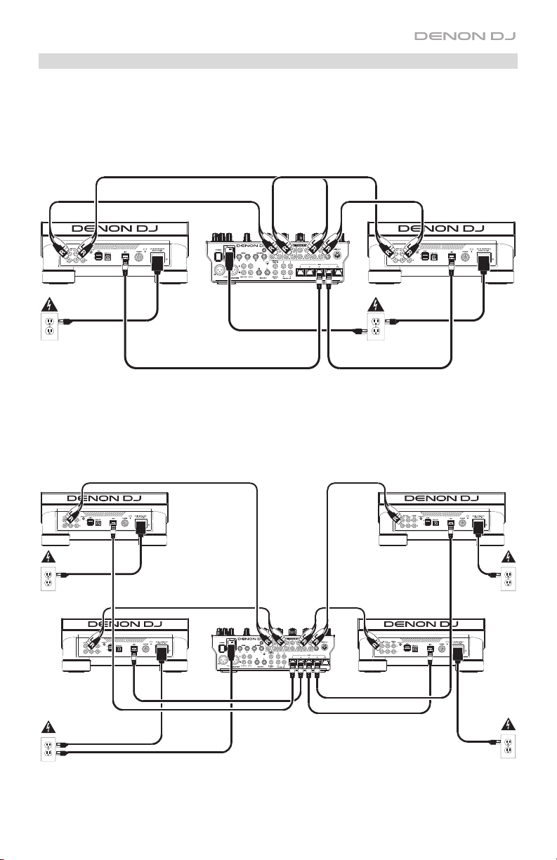
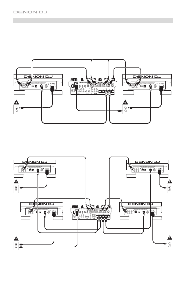
Connection Diagrams
Items shown but not listed under Introduction > Box Contents are sold separately.
Example 1
SC5000 Prime SC5000 Prime
Power outlet
Power outlet
Example 2
SC5000 Prime SC5000 Prime
Power outlet Power outlet
SC5000
Prime
Power outlet Power outlet
SC5000
Prime
3
Networking
You can use X1800 Prime to network multiple SC5000 Prime units together, enabling them to
seamlessly share timing and BPM information with X1800 Prime (to synchronize effect tempos) as
well as track and user profile data with other SC5000 Prime units.
This feature provides some advantages while performing. For instance, if you are using four SC5000
Prime units, you can use one of them to browse through all tracks on all devices (USB drives or SD
cards) connected to any of those SC5000 Prime units. You can then play any of those tracks
immediately without having to move a device from one unit to the other.
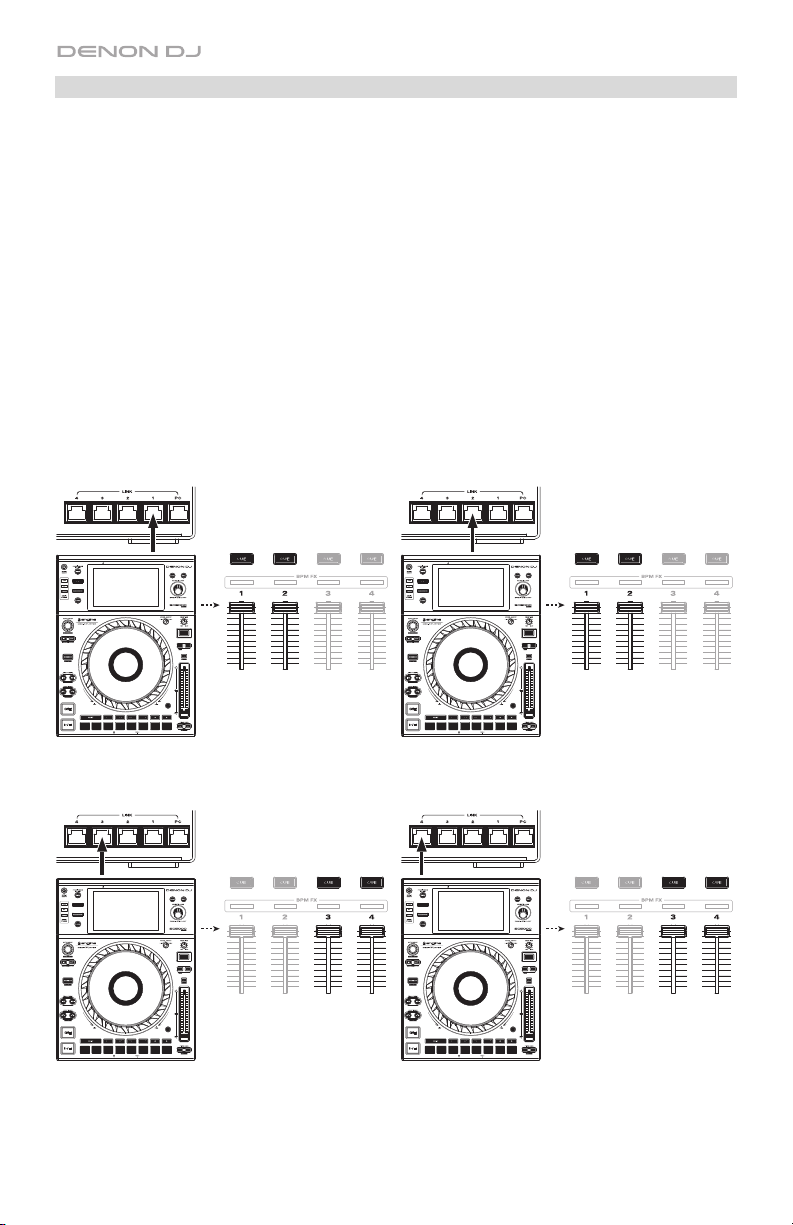
To network SC5000 Prime units together, use the included networking cables to connect each of
their Link ports to a Link port (1–4) on the rear panel of your X1800 Prime.
The Network (Media Status) light on each SC5000 Prime unit will turn on when it is properly
connected to a network.
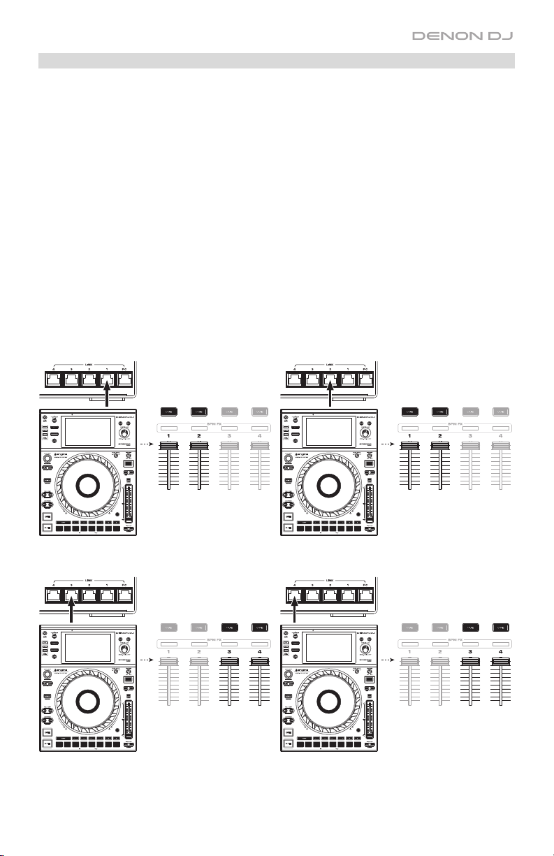
By default, X1800 Prime is set to detect and configure each SC5000 Prime automatically once you
connect their Link ports. The Link port on X1800 Prime will determine which channels that SC5000
Prime unit uses. See the scenarios below.
You can also freely assign each SC5000 Prime layer to a specific channel by changing the Engine
Connect setting on X1800 Prime. See Operation > Utility Menu > System to learn how to do this.
Layer A Layer
B
When your SC5000 Prime is connected to Link
Port 1 on X1800 Prime, Layer A will use Channel
1, and Layer B will use Channel 2.
LayerA Layer
B
When your SC5000 Prime is connected to Link
Port 3 on X1800 Prime, Layer A will use Channel
3, and Layer B will use Channel 4.
4
LayerB Layer
A
When your SC5000 Prime is connected to Link
Port 2 on X1800 Prime, Layer A will use Channel
2, and Layer B will use Channel 1.
Layer B Layer
A
When your SC5000 Prime is connected to Link
Port 4 on X1800 Prime, Layer A will use Channel
4, and Layer B will use Channel 3.
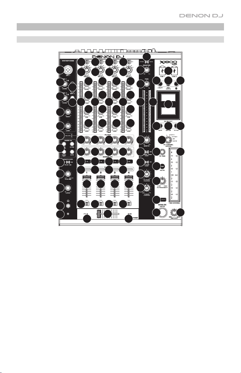
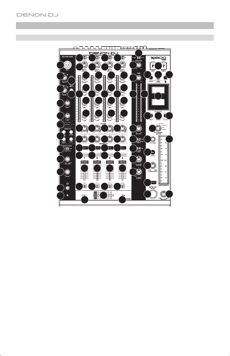
Features
Top Panel
2
2
2
2
25
26
26
29
29
1
1
3
27
28
5
3
4
4
5
4444
4444
1
1
3
4
5
5
89888
11
32
33
31
30
30
1. Input Select: Turn these knobs to select the desired audio source for each channel:
• Digital: the digital ins
• Line: the line inputs
• Phono: the phono inputs
• USB: a computer connected to a USB port. Use the USB 1/2 switch to select USB
Port 1 or USB Port 2. When set to USB Port 1 (and with a computer connected to
that port), the channel will control the corresponding channel in your software.
• DVS: a computer connected to a USB port while using control vinyl with a digital
vinyl system
2. USB 1/2: When the Input Select knob is set to USB, use these switches to select USB
Port 1 or USB Port 2 as the source. When set to USB Port 1 (and with a computer
connected to that port), the channel will control the corresponding channel in your software.
3. Level: Turn these knobs to adjust the level of the pre-fader, pre-EQ audio signal for each
channel.
4. EQ (High, Mid, Low): Turn these knobs to boost or cut the high, mid-range, and low
frequencies for each channel. You can use the Utility menu to set the type of EQ, which
determines the minimum (cut) and maximum (boost) values (see Operation > Utility Menu
> EQ).
10
7
12
13
6
15
10
7
12
13
10
10
7
7
12
12
6
6
13
13
14
15
23
22
3
24
46
49
47 48
4
21
21
20
19
18
17
6
16
34
40 41
39
38
42
44
45
37
35
43
36
5

5. Channel Level Meters: These LEDs display the audio signal level of each channel, prechannel-fader.
6. Channel Fader: Use these faders to adjust each channel’s volume level.
7. Channel Cue: Press these buttons to send each channel’s pre-fader signal to the
headphones’ cue channel. Press more than one of these buttons at the same time to send
their channels’ signals to the cue channel simultaneously.
8. Filter Knob: Turn these knobs to adjust the filter applied to each channel. Turn the knob
counter-clockwise to apply a low-pass filter. Turn the knob clockwise to apply a high-pass filter.
9. Filter Button: Press this button to enable or disable the filters (controlled by the Filter
knobs) on all channels.
10. Sweep FX Knob: Turn these knobs to adjust the balance between the “wet” signal (the
sweep effect’s output signal) and “dry” signal (audio without sweep effects applied). Select
the center (12:00) position to select an entirely dry signal.
11. Sweep FX Button: Press one of these buttons to enable or disable an effect that you can
control with the Sweep FX knobs. Only one of these buttons can be enabled at a time.
• Dub Echo: This effect is a brief echo. Starting from the center (12:00) position, turn a
Sweep FX knob counter-clockwise to decrease the length of the delay and increase
the feedback, or turn it clockwise to increase the length of the delay as well as the
feedback.
• Noise: This effect adds noise to the signal. Starting from the center (12:00) position,
turn a Sweep FX knob counter-clockwise to add pink noise, or turn it clockwise to
add white noise.
• Wash Out: This creates a transition effect. Turn a Sweep FX knob to its most
counter-clockwise (minimum) position to apply a 1-beat echo that will also mute the
channel’s normal audio signal, or turn it to its most clockwise (maximum) position to
apply a 1/2-beat echo.
• Gate: This effect applies a time-based gate effect to the signal. Starting from the
center (12:00) position, turn a Sweep FX knob counter-clockwise to apply a gate
effect synchronized with the channel’s tempo, or turn it clockwise to do the same
thing with an added effect.
12. BPM FX Indicators: These lights will illuminate to indicate if a channel is selected and
being affected by the BPM effects module (when the FX Channel Assign knob is set to
Channel 1, 2, 3, or 4).
13. Cro
ssfader Assign: Routes the audio playing on the corresponding channel to either side
of the crossfader—A (left) or B (right)—or bypasses the crossfader and sends the audio
directly to the program mix—Thru (center).
14. Crossfader: Use this crossfader to mix between the active decks.
15. Crossfader Indicators: These lights will illuminate to indicate if a side of the crossfader is
selected and being affected by effects module (when the FX Channel Assign knob is set
to X-Fader A or B).
16. X Fader Contour: Turn this knob to adjust the slope of the crossfader. Turn the knob to
the left for a smooth fade (mixing) or to the right for a sharp cut (scratching). The center
position is a typical setting for club performances.
17. Ch Fader Contour: Turn this knob to adjust the slope of the channel faders. Turn the
knob to counter-clockwise to use a slope that rises “later” (closer to the top of the fader).
Turn it clockwise to use a slope that rises “earlier” (almost immediately after moving the
fader from its minimum position). The center position is a linear slope.
18. X Fader Start: Use this switch to enable or disable crossfader start. When enabled, you
can automatically start playback the SC5000 Prime units assigned to each side of the
crossfader by moving the crossfader toward that side.
6

19. Channel Fader Start: Use this switch to enable or disable channel fader start. When
enabled, you can automatically start playback the SC5000 Prime units connected to each
channel by moving the channel fader upward.
20. Booth: Turn this knob to adjust the volume level of the booth outputs.
21. Master Level Meters: These LEDs display the audio signal level of the master mix (sent
out of the master outputs).
22. Master: Turn this knob to adjust the volume level of the master outputs.
23. Stereo/Mono Selector: Use this switch to set the channel configuration of the master
outputs: Stereo (binaural audio using separate left and right channels) or Mono (summed
monaural audio through both left and right channels).
24. Pan: Turn this knob to adjust the position of the master outputs’ signal in the stereo field.
25. Mic 1 Input: Use a standard XLR or 1/4” (6.35 mm) cable (not included) to connect a
standard dynamic microphone to this input. Use the Mic 1 Level knob on the top panel to
control the volume level.
26. Mic 1/2 Level: Turn these knobs to adjust the volume levels of the corresponding
microphone inputs. The light next to each knob indicates the current signal level by its
color: green (normal/optimal) or red (maximum/peak).
27. Mic On/Off: Press these buttons to activate or deactivate the corresponding microphone.
28. Talk Over: Press this button to activate or deactivate the “talkover” feature, which automatically
reduces the volume level of the master mix when you speak into the microphone. You can use
the Utility menu to set how much the master mix volume level is lowered and how quickly it
returns to its normal level (see Operation > Utility Menu > Microphone).
29. Mic EQ (High, Low): Turn th
ese knobs to boost or cut the high and low frequencies for
both microphones.
30. Headphone Outputs: Connect headphones to these 1/4” (6.35 mm) and 1/8” (3.5 mm)
jacks for monitoring the signal. Turn the Headphone Level knob to control the volume.
31. Headphone Level: Turn this knob to adjust the volume of the headphones.
32. Split Cue: When this switch is in the On position, the headphone audio will be “split” such
that all channels sent to cue channel are summed to mono and sent to the left headphone
channel and the master mix is summed to mono and sent to the right channel. When the
switch is in the Off position, the cue channel and master mix will be “blended” together.
33. Cue Mix: Turn this knob to adjust the balance between the cue output and the master mix
output in the headphones.
34. Displays: These displays show current information about the effects and tempo as well as
the Utility menu.
35. FX On/Off: Press this button to turn the BPM effects module on or off.
36. Wet/Dry: Turn this knob to adjust the balance between the “wet” signal (the BPM effect
module’s output signal) and “dry” signal (audio without BPM effects applied).
37. Instant: Press this button to enable or disable Instant FX Mode for the FX touch strip.
38. FX Channel Assign: Turn this knob to select the channel to which the BPM effects
module will apply its effects: Channel 1, 2, 3, or 4; X-Fader A or B (either side of the
crossfader); Mic (both microphone signals); or Master (the master mix).
39. FX Select/Enter: Turn this knob to select an effect. While in the Utility menu, turn this
knob to select an option, and press it to confirm your choice or enter a submenu.
ack: Press this button to return to the previous screen in the Utility menu.
40. B
41. FX Cue: Press this button to preview the BPM effects in the headphones’ cue channel.
Not all BPM effects can be previewed, though.
7
42. FX Time: Turn this knob to select the rate that the BPM effect module will use. Press the knob
to switch between adjusting the rate as a time division and the rate in milliseconds. (A
corresponding light along the FX touch strip will illuminate to indicate the current time division.)
43. FX Touch Strip: When the Instant button is off (disabled), tap an area of this touchcapacitive strip to select the time division that the BPM effect module will use. A
corresponding light along the strip will illuminate to indicate the current time division. If the
current time division is not a quantization value shown on the strip (e.g., the BeatBreak
effect), then none of the lights will illuminate.
When the Instant button is on (enabled), tap and hold your finger on the strip to activate
the effects, and then drag your finger up or down to adjust the time division of the effect.
44. Tap: Tap this button at least 3 times at the desired tempo to set the rate of the BPM effect
module for the channel set by the FX Channel Assign knob (the module’s rate for other
channels will remain unchanged). The Tap button will be dimly lit when using a BPM
manually entered this way.
Press and hold this button for 1 second to synchronize the rate of BPM effect module with
the audio signal of the channel set by the FX Channel Assign knob (the module’s rate for
other channels will remain unchanged). The Tap button will be brightly lit when using a BPM
automatically detected this way, and Auto will be shown next to the BPM in the second
display. If you are using an SC5000 Prime unit with Engine Connect, the SC5000 Prime will
control the BPM effect module, and the Engine logo will be shown in the second display.
45. FX Frequency: Turn this knob to select a frequency band of the audio signal to which the
BPM effects will be applied. Select the center (12:00) position to apply effects to the entire
spectrum of frequencies.
46. Utility: Press this button to enter or exit the Utility menu, which will appear in the display.
Exiting the Utility menu also saves any changes you made.
47. MIDI Send: Press this button to send a MIDI Start message out of the USB port or MIDI
output (you can use the Utility menu to select one). The tempo will be that of the selection
of the FX Channel Assign knob. If you change the selection of the FX Channel Assign
knob, press and hold this button to send the new tempo.
48. Engine Connect: When the Lin
button to enable X1800 Prime to receive timing and BPM information (to synchronize
effect tempos) and to send track and user profile data between SC5000 Prime units.
49. USB Ports: Use standard USB cables to connect computers to these USB ports.
k ports are connected to SC5000 Prime units, press this
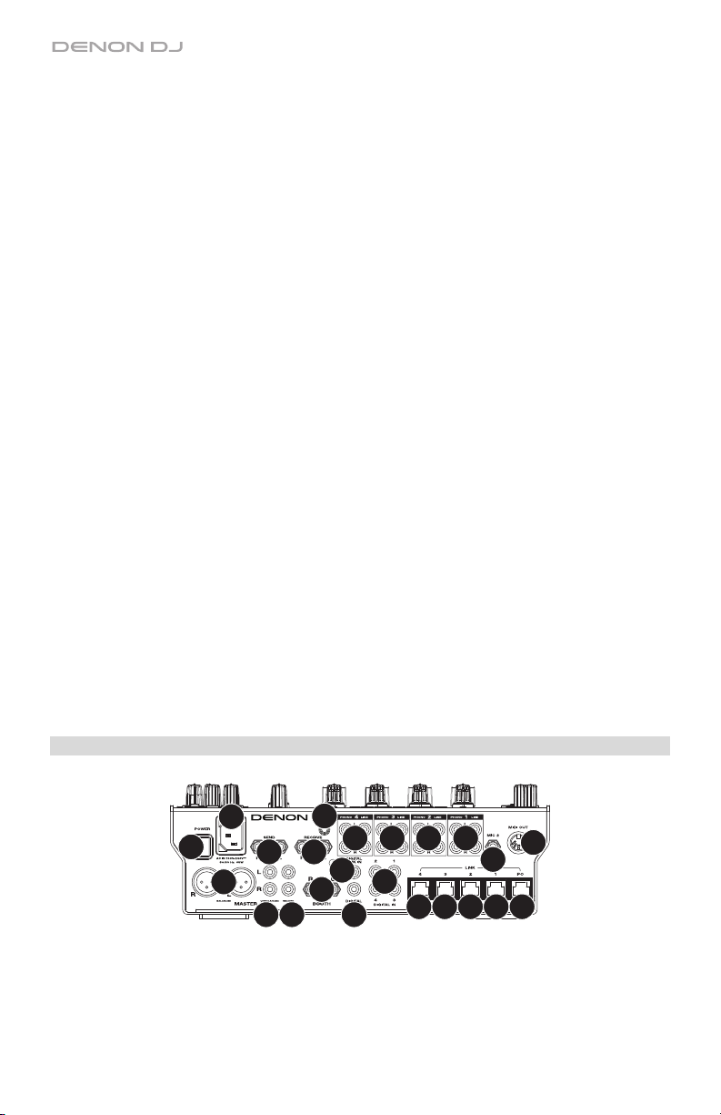
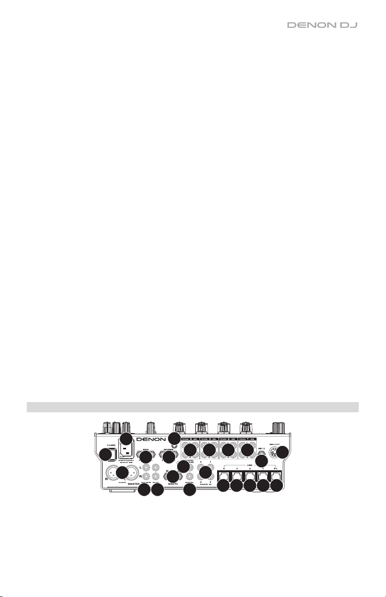
Rear Panel
1
2
4
5
1. Power Input: Use the included power cable to connect this input to a power outlet.
2. Power Button: Press this button to power X1800 Prime on or off. Power on X1800 Prime
only after you have connected all of your input devices and before you power on your
amplifiers and loudspeakers. Power off your amplifiers and loudspeakers before powering
off X1800 Prime.
8
11
8
15
16
14
3333
3
7
6
10 10 10 10
9
13
12

3. Link Ports: Use standard networking cables to connect these ports to your SC5000 Prime
units and/or to your computer. Each networked SC5000 Prime can use these connections
share timing and BPM information with X1800 Prime (to synchronize effect tempos) as well
as track and user profile data with other SC5000 Prime units.
4. Master Outputs (balanced XLR): Use standard XLR cables to connect these outputs to
loudspeakers or an amplifier system. Use the Master knob on the top panel to control the
volume level.
5. Master Outputs (unbalanced RCA): Use standard RCA cables to connect these outputs to
loudspeakers or an amplifier system. Use the Master knob on the top panel to control the
volume level.
6. Record Outputs (RCA): Use standard RCA cables to connect these outputs to a recording
interface, external mixer, or other device. Use the Utility menu to select whether or not the
mix sent to these outputs will include the microphones’ audio signal (see Operation >
Utility Menu > Microphone).
7. Booth Outputs (1/4”/6.35 mm, TRS): Use standard 1/4”/6.35 mm cables to connect these
outputs to booth monitors or a booth amplifier system. Use the Booth knob on the top
panel to control the volume level. Use the Utility menu to select whether or not the mix
sent to these outputs will include the microphones’ audio signal (see Operation > Utility
Menu > Microphone).
8. Send Outputs (1/4”/6.35 mm, TRS): Connect these outputs to the inputs of an external
effects module or other device. You can use the Utility menu to set the level of this audio
signal (see Operation > Utility Menu > Advanced Audio).
9. Receive Inputs (1/4”/6.35 mm, TRS): Connect these inputs to the outputs of an external
effects module or other device. You can use the Utility menu to set the level of this audio
signal (see Operation > Utility Menu > Advanced Audio).
10. Phono/Line Inputs (RCA): Use standard RCA cables to connect these line-level or phonolevel inputs to an external audio source. Use the input selectors
on the top panel to set
whether the signal from the line-level inputs or phono-level inputs will be sent to each channel.
11. Grounding Terminal: If you are using phono-level turntables with a grounding wire,
connect the grounding wire to this terminal. If you experience a low “hum” or “buzz”, this
could mean that your turntables are not grounded.
Note: Some turntables have a grounding wire built into the RCA connection and, therefore,
nothing needs to be connected to the grounding terminal.
12. Mic 2 Input (1/4”/6.35 mm, TRS): Use a standard 1/4” (6.35 mm) cable (not included) to
connect a standard dynamic microphone to this input. Use the Mic 2 Level knob on the
top panel to control the volume level.
13. MIDI Output (5-pin DIN): Use a standard MIDI cable to connect this output to the MIDI
input of an optional external MIDI device. You can use the MIDI Send button to send MIDI
Start messages from this output. You can also use the Utility menu to enable or disable
this connection (see Operation > Utility Menu > System).
14. Digital In (digital RCA): Use digital RCA cables to connect these 24-bit/96 KHz inputs to
the digital outputs of your Denon DJ SC5000 Prime units.
15. Digital Link In (digital RCA): If you are using more than one X1800 Prime unit, use a digital
RCA cable to connect this input to the digital out of another X1800 Prime.
16. Digital Out (digital RCA): Use a digital RCA cable to connect this output to the digital input of
another X1800 Prime unit or an external interface, mixer, or other device. Use the Utility menu
to set the level of the outgoing signal (see Operation > Utility Menu > Advanced Audio).
9

Operation
Effects
BPM Effect Module
The built-in effect module enables you to apply any one of several effects to specific channels
based on its current tempo.
To turn the BPM effect module on or off, press FX On/Off.
To select the channel to which the BPM effect module will apply its effects, turn the FX
Channel Assign knob. The options are: Channel 1, 2, 3, or 4; X-Fader A or B (either side of
the crossfader); Mic (both microphone signals); or Master (the master mix).
To apply or remove the effect to or from the cue channel, press FX Cue. When the button
is lit, effects will be applied to the headphones’ cue channel only.
To select an effect, turn the FX Select/Enter knob.
These are the available effects:
• Echo: This effect adds echoes of the original signal.
• Delay: This effect adds repeated instances of the original signal that decay over time.
• Ping Pong: This is a stereo delay effect where the rate of delay is different between the
left and right channels.
• Trans (transition): This effect cuts off the original signal at a regular rate.
• Flanger: This effect adds a slightly delayed copy of the original signal to create a comb-
filter effect (often referred to as resembling a jet plane engine).
• Filter: This effect varies the filter cutoff frequency at a regular rate.
• Phaser: This effect adds a copy of the original signal with its phase shifted slightly to
create a subtle, modulatory effect.
• Reverb: This effect adds reverberation to the original signal. The amount of delay
depends on the tempo.
• Roll: This effect samples the current audio signal and repeats it at a regular rate based on
the current time division.
• RevRoll (reverse roll): This effect samples the current audio signal and repeats it
backward at a regular rate based on the current time division.
• B
eatBreak: This effect samples the 4 beats of each bar of the original signal and replays
them (within the same bar) according to a preset pattern, creating a “stuttering,”
“breakbeat” effect.
To select a pattern to use, turn the FX Time knob to select Pattern 0–15, as shown in
the second display. The 16 blocks ( █ ) and/or lines ( __ ) below it indicate the rhythm of
the current pattern similarly to a drum machine’s step sequencer: a block represents a
“hit”/”strike” and a line represents a rest.
Examples:
indicates a hit on each beat.
indicates a hit on every 8th note.
indicates a hit on every 16th note (every
note of the pattern).
Use the Utility menu to edit the patterns (see Utility Menu > Advanced Audio).
10

• Scratch: This effect alternates between normal and reverse playback of each beat, creating a
vinyl-scratching effect.
• SendRtn (send/return): This option will enable the send outputs and receive inputs, allowing
you to use external effects on the signal.
All of the BPM effects are time-based, so the BPM effect module offers several ways for you enter or
detect the tempo it will use.
To adjust the time division of the BPM effect module, do either of the following:
• Make sure the time division (__ Beat) is selected in the lower display (if it is not, press
the FX Time knob), and then turn the FX Time knob to select another time division.
• When the Instant button is off, tap an area of the FX touch strip to select a time division.
A corresponding light along the strip will illuminate to indicate the current time division.
To adjust the rate of the BPM effect module in milliseconds, make sure the millisecond rate
(__ ms) is selected in the lower display (if it is not, press the FX Time knob), and then turn the
FX Time knob to adjust it.
To enter a new tempo, press Tap at least 3 times at the desired tempo. This will set the rate of the BPM
effect module for the channel set by the FX Channel Assign knob (the module’s rate for other channels
will remain unchanged). The Tap button will be dimly lit when using a BPM manually entered this way.
To detect the tempo automatically, press and hold Tap/-Auto for 1 second. This will synchronize the
rate of BPM effect module with the audio signal of the channel set by the FX Channel Assign knob (the
module’s rate for other channels will remain unchanged). The Tap button will be brightly lit when using a
BPM automatically detected this way, and Auto will be shown next to the BPM in the second display.
Note: If you are using an SC5000 Prime unit with Engine Connect, the SC5000 Prime will control
the BPM effect module, and the Engine logo will be shown in the second display.
To adjust the tempo manually, press and hold Tap/-Auto, and then turn the FX Time knob to
adjust the BPM in increments of 1. While still holding Tap/-Auto, press and turn the FX Time knob
to adjust the BPM in increments of 0.1.
You can easily adjust the balance between the “wet” signal (the BPM effect module’s output signal)
and “dry” signal (audio without effects applied).
To adjust the balance between the “wet” and “dry” signals, turn the Wet/Dry knob. Alternatively,
use the FX touch strip while in Instant FX Mode (see below).
Normally, you would apply effects to the entire frequency spectrum, but X1800 Prime also lets you
apply them to an isolated frequency band of the audio signal (of the selected channel).
To select the frequency band, turn the FX Frequency knob. Select the center (12:00) position
to apply effects to the entire spectrum of frequencies.
Instant FX Mode enables you to use the FX touch strip to activate the effect and adjust its time
division simultaneously.
To enable or disable Instant FX Mode, press Instant. The button will light up when it is enabled.
To activate the effect, tap and hold your finger on the FX touch strip, and then drag your
finger up or down to adjust the time division of the effect.
Sweep FX
Sweep FX enable you to apply one of four effects to the four channels and “sweep” them using the
Sweep FX knobs. You can apply only one sweep effect at a time.
To activate a sweep effect, tap one of the Sweep FX buttons: Dub Echo, Noise, Wash Out, or
Gate. The button will light up when activated. Only one of these buttons can be enabled at a time.
To deactivate a sweep effect, tap the lit Sweep FX button. Alternatively, press a different Sweep FX
button to activate it, which will deactivate the other.
11

These are the available effects and how each one is controlled by the Sweep FX knobs. For all sweep
effects, the center (“12:00”) position of the Sweep FX knob is the minimum position (the effect is not
applied). Turning it clockwise or counter-clockwise from this position can produce different results.
• Dub Echo: This effect adds a brief echo. Turn a Sweep FX knob counter-clockwise to
decrease the length of the delay and increase the feedback, or turn it clockwise to increase the
length of the delay as well as the feedback.
• Noise: This effect adds noise to the signal. Turn a Sweep FX knob counter-clockwise to add
pink noise, or turn it clockwise to add white noise.
• Wash Out: This creates a transition effect. Turn a Sweep FX knob to its most counterclockwise (minimum) position to apply a 1-beat echo that will also mute the channel’s normal
audio signal, or turn it to its most clockwise (maximum) position to apply a 1/2-beat echo.
• Gate: This effect applies a time-based gate effect to the signal. Turn a Sweep FX knob
counter-clockwise to apply a gate effect synchronized with the channel’s tempo, or turn it
clockwise to do the same thing with an added effect.
Utility Menu
The Utility menu enables you to customize various settings on X1800 Prime that affect the audio
signal routing, effects module, input and output levels, and more.
To enter or exit the Utility menu, press Utility. Exiting the Utility menu also saves any changes you made.
While in the Utility menu, you can do any of the following:
• To select an option, turn the FX Select/Enter knob.
• To confirm your choice or enter a submenu, press the FX Select/Enter knob.
• To return to the previous screen, press Back.
Below are descriptions of the different submenus in the Utility menu:
EQ
These settings determine how the Channel EQ knobs work.
• Type: Select ISO to set the Channel EQ knobs’ ranges to -∞ to +6dB/+10dB (as labeled).
Select EQ to set the Channel EQ knobs’ ranges to -24dB to +6dB (for other players that may
need this setting).
• High Cross Over: This is the crossover frequency between the High and Mid EQ knobs when
the Type is set to ISO: 1000Hz–8000Hz (in varying increments).
• Low Cross Over: This is the crossover frequency between the Mid and Low EQ knobs when
the Type is set to ISO: 100Hz–800Hz (in varying increments).
• Reset EQ Default: Select OK to return these Channel EQ settings to their default values, or
select Cancel to return to the previous menu.
Filter
• Resonance: This is the resonance of the filters on Channels 1–4 (i.e., how much the frequencies
just beyond the cutoff frequency are allowed to pass through the filter). 0 is a flat setting
(frequencies just beyond the cutoff frequency won’t be heard at all), while 15 yields a high
resonance (the cutoff frequency is not as “strict,” so some adjacent frequencies will be heard).
Headphone
• Attenuation: This is the gain level of the headphone output: -15dB to 0dB.
12

Microphone
These settings affect the microphones.
• Gain: This is the gain level of the microphone inputs: -10dB to +10dB.
• Talk Over Level: This setting determines how much the master mix volume level is lowered when the
microphone talkover feature is activated: -20dB to -40dB.
• Talk Over Resume: While using the talkover feature, the master mix volume will return to its normal
level after the microphone input detect no incoming signal. This setting determines whether that
transition occurs moderately (Normal) or quickly (Fast).
• EQ High: This is the frequency band that will be affected by the High Mic EQ knob: 1000Hz–4000Hz
(in varying increments).
• EQ Low: This is the frequency band that will be affected by the Low Mic EQ knob: 500Hz–2000Hz (in
varying increments).
• Booth Receive: Select On to allow the microphone signal to be sent to the booth outputs and record
outputs. Select Off to send the microphone signal to the master outputs only.
• Reset Mic Default: Select OK to return the Mic settings to their default values, or select Cancel to
return to the previous menu.
Advanced Audio
These settings determine the mixer’s digital operation and other advanced functions.
• Sampling Rate: This is the sampling rate of the USB audio signal: 44.1kHz, 48kHz, or 96kHz.
• Master Out Level: This is an offset to the volume level of the master outputs: -15dB to 0dB.
• Booth Out Level: This is an offset to the volume level of the booth: -15dB to 0dB.
• USB Audio: These settings determine the routing and levels of USB audio.
o CH1–4/Master/Cue Assign: These settings determine which USB audio channels (1/2–9/10) will
receive the audio signal from Channels 1–4 (CH1–CH4), the master mix (Master), and the cue
channel (Cue).
o Output Level: This is an offset to the volume level of the master mix sent to your computer over
a USB connection: -20dB to +20dB.
o Ch Input Level: This is an offset to the volume level of the audio signals sent to Channels 1–4
from your computer over a USB connection: -20dB to +20dB.
• DVS Setup: For Channels 1–4 (CH1–CH4), select the input level each one will use when its input
selector is set to DVS. Select Phono to use control vinyl records or Line to use control CDs.
• Digital Settings:
o Digital Out:
20dB to +20dB.
o Digital Link: Select On to sum the outgoing signal before the Master knob and Booth knob,
which you can use to control their output level. Select Off to sum the outgoing signal after the
Master knob and Booth knob, which will have no effect on the output level.
o Link Level: This is an offset to the volume level of the audio signal sent to the Digital Link In: -
20dB to +20dB.
• Cross Fader Cut: These settings determine how far you must move the crossfader from each side
(Fader Cut A or B) for it to start affecting the audio signal: -2.0mm to 2.0mm
• FX Edit:
o FX Return: This is the unity level for the send outputs and receive inputs: -10dB–0dB. You may
need to adjust this setting based on the types of external effects you are using.
o Beat Break Edit: This menu enables you to select, edit, and store patterns for the BeatBreak
effect. See Effects > BPM Effect Module for more information about how this effect works.
To edit a pattern:
1. Turn the FX Select/Enter knob to select a pattern (1–16), and then press it.
2. Turn the FX Select/Enter knob to select one of 12 16th-notes in the pattern. You cannot
3. Press Back to return to the previous screen.
This is an offset to the volume level of the audio signal sent from the digital out: -
edit the four
main beats of the pattern; they will always sound because they contain the
audio being sampled.
Press the FX Select/Enter knob to change the beat from a “hit”/”strike” ( █ ) to a rest ( __ )
or vice versa.
Repeat this step, if desired.
13

o FX List Customize: Use this screen to customize the order of effects. Turn the FX
Select/Enter knob to select an effect from the list of available ones on the left side,
and then press the knob to add the effect to the new order on the right side. Repeat
this step for each effect, or select -Cancel- to return to the previous screen. After
you have done this for all effects, select -End- to save your customized list.
o BPM FX On Color: This setting determines the color of the FX On/Off button while it
flashes: red, spring green, green, light blue, blue, yellow, orange, or purple.
System
These settings determine overall operation.
• Info: These screens contain information about the current firmware version and network
information.
o Version: This is the current X1800 Prime firmware version.
o IP Address: This is the IP address that X1800 Prime is using.
o MAC Address: This is the MAC address that X1800 Prime is using.
• Engine Connect: Select Auto to enable X1800 Prime to automatically receive timing and
BPM information (to synchronize effect tempos) from SC5000 Prime units connected to
its Link ports and to send track and user profile data between them. X1800 Prime will
also automatically detect and configure each SC5000 Prime once you connect their Link
ports. Select Manual to disable automatic linking and only activate this feature manually
by pressing and holding the Engine Connect button until the Channel Assignment
screen appears on the SC5000 Prime units. You can then freely assign each SC5000
Prime layer to a specific channel.
• Cue Settings:
o Cue Solo Mode: Select On to use the Channel Cue buttons as “solo” buttons
(pressing one will mute all other channels). Select Off to use them as normal cue
buttons (pressing one will send its signal to the cue channel).
o Cue 1–4 Color: This setting determines the color of the Cue buttons for each
channel: red, spring green, green, light blue, blue, yellow, orange, or purple.
o Reset Cue Defaults: Select OK to return the Cue settings to their default values, or
select Cancel to return to the previous menu.
• Network Settings:
esh IP Address: Select OK to renew your IP address, which reestablishes the
o Refr
connection between your X1800 Prime and any SC5000 Prime units connected to
the Link ports. Select Cancel to return to the previous screen.
• MIDI: These are MIDI settings that determine the MIDI channels and connections used.
o Clock Send: These settings determine whether or not X1800 Prime will send MIDI
Clock messages over each of these connections. For each option, select On to
enable transmission or Off to disable it.
USB: This applies to both USB Ports 1 and 2. If you are using X1800 Prime to
control software, set this to On.
5pin: This applies to the MIDI out.
o Active Send: These settings determine whether or not X1800 Prime will send normal
MIDI messages over each of these connections. For each option, select On to
enable transmission or Off to disable it.
USB: This applies to both USB Ports 1 and 2. If you are using X1800 Prime to
control software, set this to On.
5pin: This applies to the MIDI out.
• Factory Reset: Select OK to restore X1800 Prime to its factory default settings (wait a
few seconds after selecting this before resuming normal operation). Select Cancel to
return to the previous screen.
14

Guía del usuario (Español)
Introducción
Características:
• Mezclador digital de 4 canales con (4) canales conmutables de fonográfico/línea
• Sección de efectos de BPM con aislamiento de banda controlado por frecuencia
• Conexiones de audio USB dobles para software y dispositivos de audio
• Perillas dedicadas para barrido y efectos de BPM—efectos de alta calidad para cada
canal con un solo giro de la perilla
• Ecualizador expresivo—elija modos clásicos o de aislamiento y un control de resonancia
de filtro ajustable
• Protocolo Engine Connect para efectos vinculados a la grilla de beats
• Expresivo crossfader Denon DJ Flex-Fader
• Conecte efectos e instrumentos basados en MIDI
• Salida digital de 24 bits/ 96 kHz para una calidad de audio impecable
• Sus nítidas pantallas OLED permiten realizar ajustes precisos en base a los menús
• (4) entradas digitales para mezclas de audio de alta resolución
• Concentrador LAN para hasta cuatro jugadores o accesorios
• Construcción metálica robusta
Contenido de la caja
X1800 Prime Guía del usuario
Cable USB Manual sobre la seguridad y garantía
Cable de alimentación
Soporte
Para obtener la información más reciente acerca de este producto (documentación,
especificaciones técnicas, requisitos de sistema, información de compatibilidad, etc.) y
registrarlo, visite denondj.com.
Para obtener soporte adicional del producto, visite denondj.com/support.
Instalación
1. Asegúrese de que todos sus dispositivos estén apagados o que todos sus niveles de
volumen estén en sus posiciones mínimas.
2. Conecte las salidas de audiode su reproductor de medios a las entradas del X1800 Prime.
3. Si está utilizando unidades SC5000 Prime conecte sus puertos Link a los puertos Link del
X1800 Prime según uno de los siguientes ejemplos de diagramas de conexión.
4. Conecte otros dispositivos (giradiscos, auriculares, amplificadores de potencia, altavoces,
etc.) a las entradas o las salidas del X1800 Prime.
5. Conecte todos sus dispositivos a sus fuentes de corriente.
Al iniciar una sesión, encienda (1) sus reproductores de medios y las demás fuentes de
entrada, (2) el SC5000 Prime y luego (3) los dispositivos de salida.
Al finalizar una sesión, apague (1) los dispositivos de salida, (2) el SC5000 Prime y luego (3)
sus reproductores de medios y las demás fuentes de entrada.
15
Diagramas de conexion
Los elementos que se muestran pero que no se enumeran en Introducción > Contenido de
la caja se venden por separado.
Ejemplo 1
SC5000 Prime SC5000 Prime
Suministro
electrico
Suministro
electrico
Ejemplo 2
SC5000 Prime SC5000 Prime
Suministro
electrico
SC5000
Prime
Suministro
electrico
16
Suministro
electrico
SC5000
Prime
Suministro
electrico
Conexiones en red
Puede utilizar el X1800 Prime para conectar en red múltiples unidades SC5000 Prime
permitiéndoles compartir de forma transparente información de sincronización y BPM con el
X1800 Prime (a fin de sincronizar los tempos de los efectos) así como también los datos de la
pista y del perfil del usuario con otras unidades SC5000 Prime.
Esta característica brinda algunas ventajas para sus actuaciones. Por ejemplo, si está usando
cuatro unidades SC5000 Prime, puede usar una de ellas para explorar todas las pistas en
todos los dispositivos (unidades USB o tarjetas SD) conectadas a cualquiera de estas
unidades SC5000 Prime. Entonces podrá reproducir cualquiera de estas pistas
inmediatamente sin tener que trasladar un dispositivo desde una unidad a otra.
Para conectar unidades SC5000 Prime entre sí mediante una red, utilice los cables de
conexión en red incluidos para conectar cada uno de sus puertos Link a un puerto Link (1–4)
en el panel trasero de su X1800 Prime.
La Luz Network (Media Status) en cada unidad SC5000 Prime se encenderá cuando esté
correctamente conectada a una red.
Configuración automática con SC5000 Prime:
Puerto Link 1 Puerto Link 2
Layer A Layer
B
Puerto Link 3 Puerto Link 4
LayerA Layer
B
LayerB Layer
A
Layer B Layer
A
17
Características
Panel superior
15
23
22
3
24
46
49
47 48
4
21
21
20
19
18
17
6
16
34
40 41
39
38
42
44
45
37
35
43
36
2
2
2
2
25
26
26
29
29
1
1
3
27
28
5
3
4
4
5
4444
4444
1
1
3
4
5
5
89888
11
32
33
31
30
30
1. Input Select: Gire estas perillas para seleccionar la fuente de audio deseada para cada canal:
• Digital: las entradas digitales
• Line: las entradas de línea
• Phono: las entradas fonográficas
• USB: un ordenador conectado a un puerto USB. Utilice el interruptor USB 1/2 para
seleccionar el puerto USB 1 o el puerto USB 2. Cuando lo ajuste a puerto USB 1 (y
con un ordenador conectado a ese puerto), el canal controlará el canal
correspondiente en su software.
• DVS: un ordenador conectado al puerto USB mientras usa un vinilo de control con
un sistema de vinilo digital
2. USB 1/2: Cuando la perilla Input Select se ajusta a USB, utilice estos interruptores para
seleccionar el puerto USB 1 o el puerto USB 2 como la fuente. Cuando lo ajuste a puerto
USB 1 (y con un ordenador conectado a ese puerto), el canal controlará el canal
correspondiente en su software.
3. Level: Gire estas perillas para ajustar el nivel de la señal de audio del pre-fader y preecualizador de cada canal.
4. Ecualizador (High, Mid, Low): Gire estas perillas para aumentar o disminuir las frecuencias
altas, medias y bajas de cada canal. Puede usar el menú Utilidades para ajustar el tipo de
ecualizador, el cual determina los valores mínimos (corte) y máximos (refuerzo) (consulte
Funcionamiento > Menú Utilidades > EQ).
18
10
12
13
10
10
10
7
7
7
7
12
12
12
6
6
6
13
13
13
15
14

5. Medidores de nivel de canal: Estos LED muestran el nivel de la señal de audio de cada
canal, previo al fader del canal.
6. Fader del canal: Utilice estos faders para ajustar el nivel del volumen de cada canal.
7. Cue del canal: Pulse estos botones para enviar la señal pre-fader de cada canal al canal
de cue de los auriculares. Pulse más de uno de estos botones al mismo tiempo para
enviar las señales de sus canales al canal de cue simultáneamente.
8. Perilla Filter: Gire estas perillas para ajustar el filtro aplicado a cada canal. Gire esta perilla en
sentido antihorario para aplicar un filtro pasabajos. Gire esta perilla en sentido horario para
aplicar un filtro pasaaltos.
9. Botón Filter: Pues este botón para activar o desactivar los filtros (controlados por las
perillas Filter) en todos los canales.
10. Perilla Sweep FX: Gire estas perillas para ajustar el balance entre la señal “con efecto” (la
señal de salida del efecto de barrido) y la señal “sin efecto” (el audio sin los efectos de
barrido aplicados). Seleccione la posición central (12:00) para seleccionar una señal sin
absolutamente ningún efecto.
11. Botón Sweep FX: Pulse uno de estos botones para activar o desactivar un efecto que pueda
controlar con las perillas Sweep FX. Sólo se puede activar uno de estos botones a la vez.
• Dub Echo: Este efecto consta de un breve eco. Partiendo de la posición central
(12:00) gire una perilla Sweep FX en sentido antihorario para disminuir la longitud del
delay (retardo) y aumentar la retroalimentación o gírela en sentido horario para
aumentar la longitud del delay así como también la retroalimentación.
• Noise: Este efecto le agrega ruido a la señal. Partiendo de la posición central (12:00),
gire una perilla Sweep FX en sentido antihorario para agregar ruido rosa o gira en
sentido horario para agregar ruido blanco.
• Wash Out: Este botón crea un efecto de transición. Gire una perilla Sweep FX a su
posición más antihoraria (mínimo) para aplicar un eco de 1 beat que también
silenciara la señal de audio normal del canal o gírela a su posición más horaria
(máxima) para aplicar un eco de 1/2 beat.
• Gate: Este efecto aplica un efecto de compuerta basada en el tiempo a la señal.
Partiendo de la posición central (12:00), gire una perilla Sweep FX en sentido
anti
horario para aplicar un efecto de compuerta sincronizado con el tempo del canal
o gírela en sentido horario para realizar lo mismo con un efecto agregado.
12. Indicadores BPM FX: Estas luces se encienden para indicar si un canal está seleccionado
y afectado por el módulo de efectos de BPM (cuando la perilla FX Channel Assign esta
ajustada a Channel 1, 2, 3 o 4).
13. Asignación del crossfader: Aplica el audio que se reproduce en el canal correspondiente
a cualquiera de los lados del crossfader—A (izquierda) o B (derecha)—o puentea el
crossfader y envía el audio directamente a la mezcla del programa—Thru (centro).
14. Crossfader: Utilice este crossfader para mezclar las bandejas activas.
15. Indicadores del crossfader: Estas luces se encienden para indicar si un lado del
crossfader está seleccionado y afectado por el módulo de efectos (cuando la perilla FX
Channel Assign se ajusta a X-Fader A o B).
16. X Fader Contour: Gire esta perilla para ajustar la pendiente del crossfader. Gire la perilla
a la izquierda para una fusión suave (mezcla) o a la derecha para un corte abrupto
(rayado). La posición central es un ajuste típico para actuaciones en clubes.
17. Ch Fader Contour: Gire esta perilla para ajustar el nivel de la salida de los faders de
canal. Gire la perilla en sentido antihorario para utilizar una pendiente que se levante “más
tarde” (más cerca del extremo del fader). Gírela en sentido horario para utilizar una
pendiente que se levante “más temprano” (casi inmediatamente después de mover el
fader de su posición mínima). La posición central es una pendiente lineal.
18. X Fader Start: Utilice este interruptor para activar o desactivar el inicio mediante
crossfader. Una vez activado, puede iniciar automáticamente la reproducción de las
unidades SC5000 Prime asignadas a cada lado del crossfader moviéndolo hacia ese lado.
19

19. Channel Fader Start: Utilice este interruptor para activar o desactivar el inicio del canal
mediante fader. Una vez activado, puede iniciar automáticamente la reproducción de las
unidades SC5000 Prime conectadas a cada canal moviendo el fader del canal hacia arriba.
20. Booth: Gire esta perilla para ajustar el nivel de volumen de las salidas de cabina.
21. Medidores de nivel maestro: Estos LED exhiben el nivel de la señal de audio de la
mezcla maestra (enviada hacia afuera por las salidas maestras).
22. Master: Gire esta perilla para ajustar el volumen de las salidas maestras.
23. Selector estéreo/mono: Utilice este interruptor para ajustar la configuración del canal de las
salidas maestras: Estéreo (audio binaural que utiliza canales izquierdo y derecho separados)
o Mono (audio monoaural sumado a través de ambos canales izquierdo y derecho).
24. Pan: Gire esta perilla para ajustar la posición de la señal de las salidas maestras en el
campo estéreo.
25. Entrada de micrófono 1: Utilice un cable XLR o de 6,35 mm (1/4 pulg.) estándar (no incluido)
para conectar a esta entrada un micrófono dinámico estándar. Utilice la perilla Mic 1 Level
(Nivel del micrófono 1) ubicada en el panel superior para controlar el nivel de volumen.
26. Mic 1/2 Level: Gire estas perillas para ajustar los niveles de volumen de las
correspondientes entradas de micrófonos. El indicador luminoso junto a cada perilla indica
el nivel actual de la señal según su color: verde (normal/óptima) o roja (máximo/pico).
27. Mic On/Off: Pues estos botones para activar o desactivar el micrófono correspondiente.
28. Talk Over: Pulse este botón para activar o desactivar la característica “hablar sobre la
mezcla”, la cual reduce automáticamente el nivel de volumen de la mezcla maestra
cuando se utiliza el micrófono. Puede usar el menú Utilidades para ajustar la medida en la
que el nivel de volumen de la mezcla maestra disminuye y que tan rápido regresa a su
nivel normal (consulte Funcionamiento > Menú Utilidades > Microphone).
29. Ecualizador del micrófono (High, Low)
: Gire estas perillas para aumentar o disminuir las
frecuencias altas y bajas de ambos micrófonos.
30. Salidas para auriculares: Conecte los auriculares a estos conectores de 6,35 mm (1/4
pulg.) y 3,5 mm (1/8 pulg.) para monitorizar la señal. Gire la perilla volumen maestro para
ajustar el volumen.
31. Nivel de auriculares: Gire esta perilla para ajustar el volumen de los auriculares.
32. Split Cue: Cuando este interruptor está en posición On (Activado), se “divide” el audio de
los auriculares de modo que todos los canales enviados al canal de cue se suma a mono y
se envía al canal del auricular izquierdo y la mezcla maestra se suma a mono y se envía al
canal derecho. Cuando el interruptor está en posición Off (Desactivado), el canal de cue y
la mezcla maestra se “combinan”.
33. Cue Mix: Gire esta perilla para ajustar el balance entre la salida de cue y la salida de la
mezcla maestra en los auriculares.
34. Pantallas: Estas pantallas muestran información actual sobre los efectos y el tempo así
como también del menú Utilidades.
35. FX On/Off: Pulse este botón para encender o apagar los efectos del módulo de BPM.
36. Wet/Dry: Gire esta perilla para ajustar el balance entre la señal “con efecto” (la señal de
salida del efecto de BPM) y la señal “sin efecto” (el audio sin los efectos de BPM aplicados).
37. Instant: Pues este botón para activar o desactivar el modo Instant FX para la tira táctil de
efectos.
38. FX Channel Assign: Gire esta perilla para seleccionar el canal al cual el módulo de
efectos de BPM aplicará sus efectos: Channel 1, 2, 3, or 4; X-Fader A o B (ambos lados
del crossfader); Mic (ambas señales de micrófono); o Master (la mezcla maestra).
39. FX Select/Enter: Gire esta perilla para seleccionar un efecto. Estando en el menú
Utilidades, gire esta perilla para seleccionar una opción y púlsela para confirmar su
selección o para entrar a un sub-menú.
40. Back: Pulse este botón para regresar a la pantalla anterior del menú Utilidades.
41. FX Cue: Pul
se este botón para monitorizar los efectos de BPM en el canal de cue de los
auriculares. Sin embargo, no todos los efectos de BPM pueden monitorizarse.
20
42. FX Time: Gire esta perilla para seleccionar la frecuencia que el módulo de efectos de BPM
utilizará. Pulse la perilla para conmutar entre un ajuste de la frecuencia como división de tiempo
y de la frecuencia en milisegundos. (Se encenderá la luz correspondiente a lo largo de la tira
táctil de efectos para indicar la división de tiempo actual).
43. Tira táctil de efectos: Cuando el botón Instant esté en la posición off (desactivado), toque un
área de esta tira táctil capacitiva para seleccionar la división de tiempo que utilizará el módulo
de efectos de BPM. Se encenderá la luz correspondiente a lo largo de la tira para indicar la
división de tiempo actual. Si la división de tiempo actual no es un valor de cuantificación
exhibido en la tira (por ej., el efecto BeatBreak), entonces nos encenderá ninguna de las luces.
Cuando el botón Instante este en la posición on (activado), toque y mantenga su dedo en la tira
para activar los efectos y luego arrastre su dedo hacia arriba o hacia abajo para ajustar la
división de tiempo del efecto."
44. Tap/-Auto: Toque este botón al menos 3 veces al tempo deseado para ajustar la velocidad del
módulo de efectos de BPM para el canal definido por la perilla FX Channel Assign (la velocidad
del módulo de los otros canales permanecerá inalterada). El botón Tap estará atenuado al usar
un valor de BPM introducido manualmente de esta forma.
Mantenga pulsado este botón durante 1 segundo para sincronizar la velocidad del módulo de
efectos de BPM con la señal de audio del canal definido por la perilla FX Channel Assign (la
velocidad del módulo de los otros canales permanecerá inalterada). El botón Tap se iluminará al
máximo cuando esté utilizando BPM detectados automáticamente de esta manera, y se
mostrará Auto junto a los BPM en la segunda pantalla. Si está utilizando una unidad SC5000
Prime con Engine Connect, el SC5000 Prime controlará el módulo de efectos de BPM y se
mostrará el logo de Engine en la segunda pantalla.
45. FX Frequency: Gire esta perilla para seleccionar una banda de frecuencia de la señal de audio a
la cual se aplicarán los efectos de BPM. Seleccione la posición central (12:00) para aplicar
efectos a la totalidad del espectro de frecuencias.
46. Utility: Pulse este botón para entrar o salir del menú de Utilidades, el cual aparecerá en la
pantalla. Al salir del menú Utilidades también se guardan todos los cambios realizados.
47. MIDI Send: Pulse este botón para enviar un mensaje de MIDI Start por el puerto USB o la
salida MIDI output (Puede usar el menú Utilidades para seleccionar uno). El tempo será el de la
selección de la perilla FX Channel Assign. Si modifica la selección de la perilla FX Channel
Assign, mantenga pulsado este botón para enviar el tempo nuevo.
48. Engine Connect: Cuando los puertos Link se conectan a unidades SC5000 Prime, pulse este
botón para permitir que el X1800 Prime reciba información de sincronización y BPM (a fin de
sincronizar los tempos de los efectos) y enviar datos de la pista y el perfil del usuario entre las
unidades SC5000 Prime.
49. Puertos USB: Utilice cables USB estándar para conectar ordenadores a estos puertos USB.
Panel trasero
1
2
4
1. Entrada de corriente: Utilice el cable de corriente incluido para conectar esta entrada a una
toma de corriente.
2. Botón de encendido: Pulse este botón para encender o apagar el X1800 Prime. Encienda el X1800
Prime después de haber conectado todos sus dispositivos de entrada y antes de encender sus
amplificadores y altavoces. Apague sus amplificadores y altavoces antes de apagar el X1800 Prime.
11
8
5
15
16
14
3333
3
7
6
10 10 10 10
9
13
12
21
Loading...