


RCD-M41
.
RCD-M41 / RCD-M41DAB
CD RECEIVER
Owner’s Manual
You can print more than one page of a PDF onto a single sheet of paper.
Contents Connections Playback Settings Tips Appendix
1
Front panel Display Rear panel Remote Index
Accessories
5
Inserting the batteries
6
Operating range of the remote control unit
6
Features
7
Part names and functions
8
Front panel
8
Display
11
Rear panel
12
Remote control unit
14
Connections
Speaker connection
18
Connecting the speaker cables
18
Connecting the subwoofer
19
Connecting speakers
19
Connecting an analog device
20
Connecting a digital device
20
Connecting a DAB/FM antenna
21
Connecting the power cord
23
Playback
Basic operation
25
Turning the power on
25
Switching the power to standby
25
Selecting the input source
26
Adjusting the volume
26
Turning off the sound temporarily (Muting)
26
Playing CDs
27
Playing CDs
27
Playing tracks in a specific order (Program playback)
28
Playing DATA CDs
29
Playing files
30
Listening to DAB/FM broadcasts
31
Listening to DAB/FM broadcasts
31
Automatically presetting FM stations (Auto Preset)
32
Presetting FM stations manually
33
Listening to preset stations
34
Setting the preset channels and changing the received frequency
on the main unit
34
RDS search
35
PTY search
36
TP search
37
Radio Text
37
CT (Clock Time)
38
Listening to DAB/DAB+ (for RCD-M41DAB only)
38
Contents Connections Playback Settings Tips Appendix
Contents
2
Front panel Display Rear panel Remote Index

Listening to music on a Bluetooth device
41
Playing music from Bluetooth device
42
Pairing with other Bluetooth devices
43
Reconnecting to this unit from a Bluetooth device
44
Turning the Bluetooth function off for high sound performance
playback
44
Listening to DIGITAL IN
45
Listening to ANALOG IN
46
Convenience functions
47
Adjusting the tone
48
Sleep timer function
49
Checking the current time
49
Switching the display’s brightness
50
Settings
Menu map
51
Menu operation
52
CLOCK SETUP
53
ALARM SETUP
53
ALARM ON/OFF
54
H/P AMP GAIN
55
SPK OPTIMISE
55
AUTO STANDBY
55
CD AUTO PLAY
56
CLOCK MODE
56
Contents Connections Playback Settings Tips Appendix
3
Front panel Display Rear panel Remote Index
Tips
Tips
58
Troubleshooting
59
Resetting factory settings
67
Appendix
Playing back DATA CDs
68
DIGITAL IN
69
Playing back Bluetooth devices
69
About Discs
70
Last function memory
72
Explanation of terms
73
Trademark information
75
Specifications
76
Index
80
Contents Connections Playback Settings Tips Appendix
4
Front panel Display Rear panel Remote Index
Thank you for purchasing this Denon product.
To ensure proper operation, please read this owner’s manual carefully before using the product.
After reading this manual, be sure to keep it for future reference.
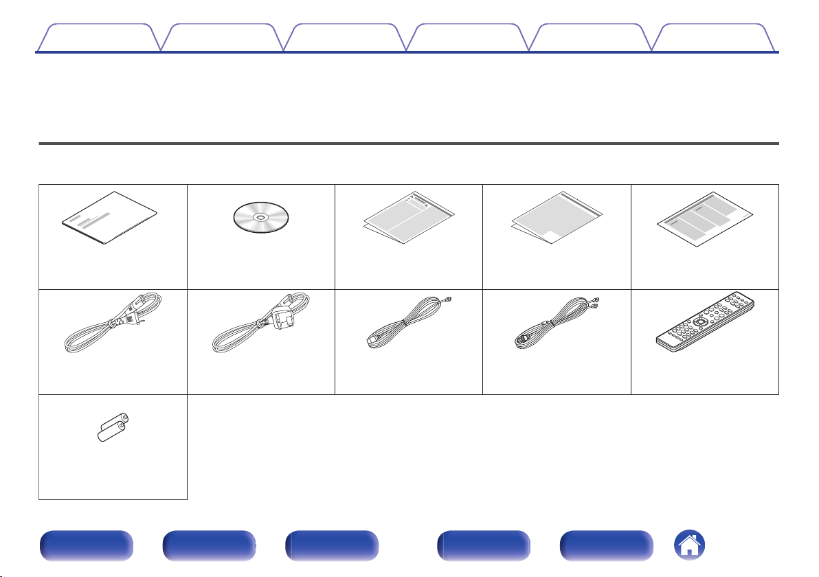
Accessories
Check that the following parts are supplied with the product.
.
Quick Start Guide CD-ROM
(Owner’s Manual)
Safety Instructions Cautions on Using Batteries Notes on radio
R03/AAA batteries
Power cord
Power cord
(for RCD-M41DAB only)
FM indoor antenna
(for RCD-M41 only)
Remote control unit
(RC-1214)
DAB/FM indoor antenna
(for RCD-M41DAB only)
Contents Connections Playback Settings Tips Appendix
5
Front panel Display Rear panel Remote Index
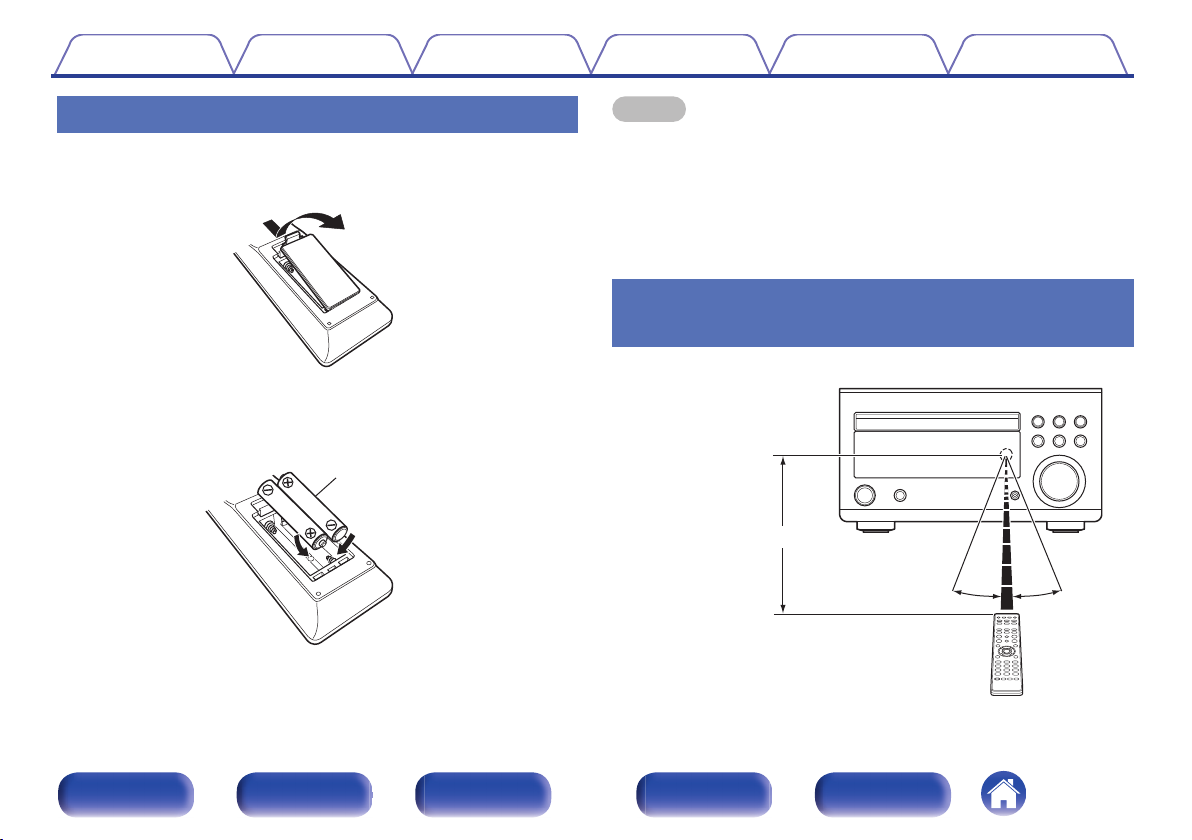
Inserting the batteries
1
Remove the rear lid in the direction of the arrow and
remove it.
.
2
Insert two batteries correctly into the battery
compartment as indicated.
.
Batteries
3
Put the rear cover back on.
NOTE
0
To prevent damage or leakage of battery fluid:
0
Do not use a new battery together with an old one.
0
Do not use two different types of batteries.
0
Remove the batteries from the remote control unit if it will not be in use for long
periods.
0
If the battery fluid should leak, carefully wipe the fluid off the inside of the battery
compartment and insert new batteries.
Operating range of the remote control
unit
Point the remote control unit at the remote sensor when operating it.
.
30°
Approx. 7 m
30°
Contents
Connections Playback Settings Tips Appendix
6
Front panel Display Rear panel Remote Index
Features
0
High quality amplifier stressing sound quality
Equipped with a 30 W + 30 W (6 Ω/ohms) high-quality amplifier circuits.
0
Weight and Dramatic sound
The board and circuit configuration has been redesigned to achieve
lower impedance. Since stable current is supplied to the power amp
and other sections, it is possible to realize as much as 30 W of power.
0
Simple & Straight circuit design for sound purity and free of
coloration
Denon’s popular M series gives you high sound quality based on the
simple & straight concept. Circuitry is uncomplicated, signal paths are
short, and all adverse influences on sound quality have been minimized.
0
Auto standby mode
This unit also provides the Auto standby mode, where it goes into the
standby state when there is no operation for 15 minutes.
0
Low standby power consumption
Designed with the environment in mind, the unit consumes just 0.3 W
while in standby mode.
0
Remote control unit
This unit is shipped with a remote control unit that has large buttons for
frequently used functions, allowing you to quickly find the desired
function.
0
High quality headphone Amp with Amp gain control
This unit is equipped with a high-quality headphone amplifier on which
the gain can be adjusted. A variety of headphones are supported.
0
2 digital (optical) inputs for TV or digital gear
You can connect audio from a TV or a media player digitally to enjoy
impressive, high-quality sound.
0
Wireless connection with Bluetooth enabled devices (v p. 44)
You can connect Bluetooth enabled devices such as smartphones and
tablets with this unit to listen to music while browsing email and Web
sites in the Internet away from this unit. In addition, this unit supports
high quality audio codecs, AAC, to enjoy music and games with a
powerful sound.
0
Bluetooth OFF mode for highest sound performance
The Bluetooth OFF mode is used to turn off the Bluetooth function, as
this function is a source of noise that affects sound quality. Suppressing
this noise enables high sound performance playback.
Contents
Connections Playback Settings Tips Appendix
7
Front panel Display Rear panel Remote Index
Part names and functions
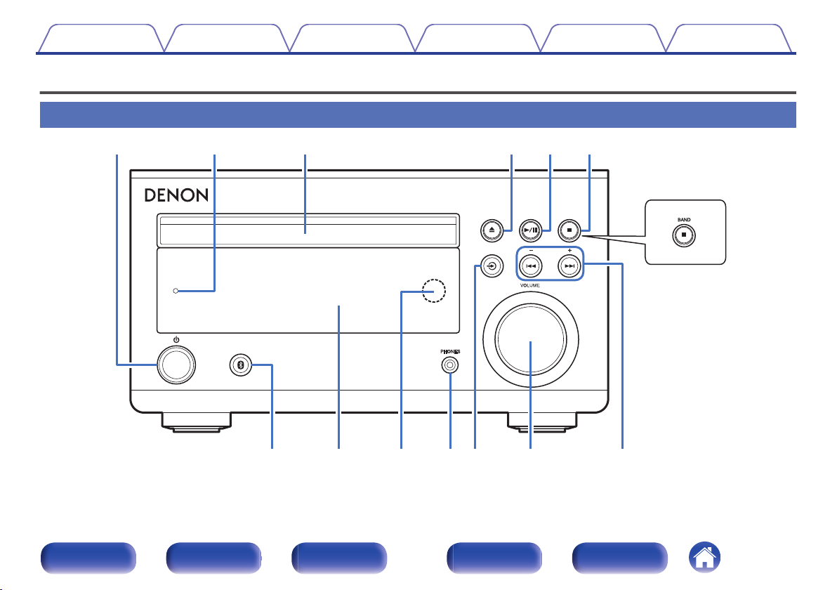
Front panel
.
RCD-M41DAB
ui Q0oQ1 Q2 Q3
qwe rty
For details, see the next page.
Contents
Connections Playback Settings Tips Appendix
8
Front panel Display Rear panel Remote Index
.
q
w e rty
uio
RCD-M41DAB
A
Power operation button (X)
Turns power to this unit on and off (standby). (v p. 25)
0
When “CLOCK MODE” is turned on, this button switches between normal
mode and Clock mode. (v
p. 56)
B
Power indicator
This is lit as follows according to the power status:
0
Power on : Green
0
Normal standby : Off
0
Bluetooth standby : Red (v
p. 44)
0
Alarm standby: Orange (v p. 53)
C
Disc tray
Used to insert a disc. (v
p. 27)
D
Disc tray open/close button (5)
Opens and closes the disc tray.
E
Play/Pause button (1/3)
Plays the track/Pauses the track.
F
Stop button (2)
Stops playback.
BAND button (for RCD-M41DAB only)
This switches between FM and DAB, when you use the tuner.
G
Bluetooth button (V)
This switches the input to Bluetooth. This is also pressed during the
pairing operation. (v
p. 41)
H
Display
This displays various pieces of information. (v p. 11)
I
Remote control sensor
This receives signals from the remote control unit. (v
p. 6)
Contents
Connections Playback Settings Tips Appendix
9
Front panel Display Rear panel Remote Index
.
Q
0
Q
1
Q
2
Q
3
RCD-M41DAB
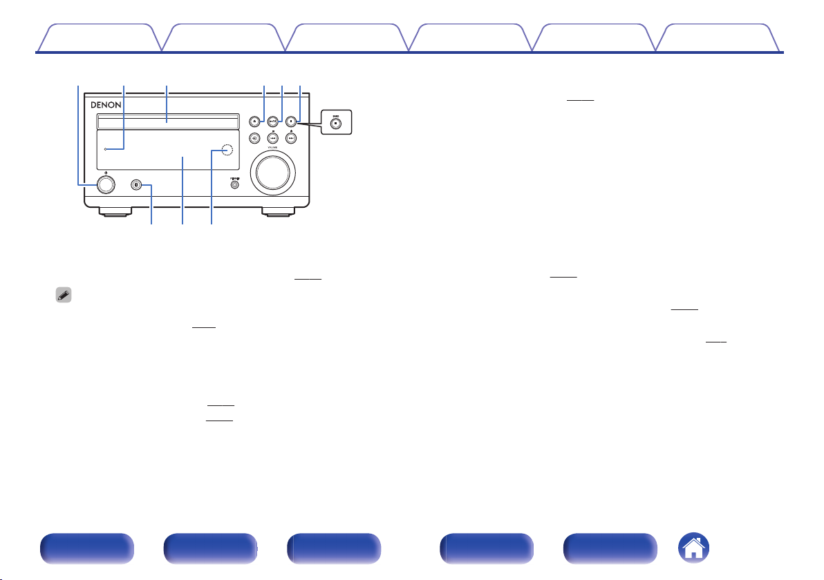
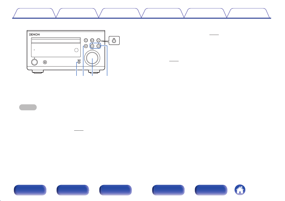
J
Headphones jack (PHONES)
Used to connect headphones.
When the headphones are plugged into this jack, audio will no longer
be output from the connected speakers.
NOTE
0
To prevent hearing loss, do not raise the volume level excessively when using
headphones.
K
Source button (q)
This select the input source. (v
p. 26)
L
VOLUME knob
This adjusts the volume level. (v
p. 26)
M
Reverse-skip/Forward-skip buttons (8, 9)
This skips to the start of the track.
Preset/Tuning buttons (–, +)
These select FM broadcast and DAB broadcast (for RCD-M41DAB
only). (v
p. 31)
Contents Connections Playback Settings Tips Appendix
10
Front panel Display Rear panel Remote Index
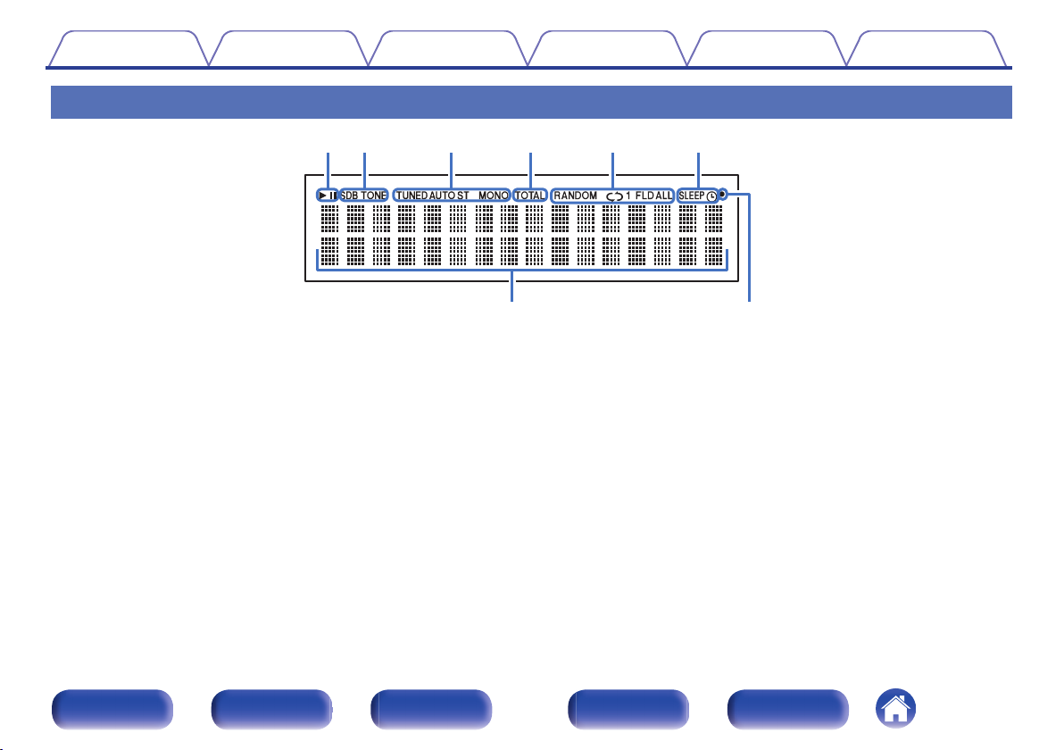
Display
.
u i
ytrewq
A
Playback mode indicators
1 : Lights up during playback.
3 : Lights up during pause.
B
Tone indicators
SDB: Lights up when the super dynamic bass function is set to “ON”.
TONE: Lights up when the tone (BASS/TREBLE) is being adjusted.
C
Tuner reception mode indicators
These light up according to the reception conditions when the input
source is set to tuner.
TUNED: Lights up when the broadcast is properly tuned in.
AUTO: Lights up when the input source is “FM AUTO”.
ST: Lights up when receiving FM stereo broadcasts.
MONO: Lights up when receiving FM monaural broadcasts.
D
TOTAL indicator
Lights up when the total number of tracks and total time of the CD are
displayed.
E
Play mode indicators
These light according to the play mode settings.
F
Timer operation indicators
SLEEP: Lights up when the sleep timer is on.
s: Lights up when the timer playback is on.
G
Information display
Various information is displayed here.
H
Remote control signal reception indicator
Lights up when a signal is received from the remote control.
Contents Connections Playback Settings Tips Appendix
11
Front panel Display Rear panel Remote Index
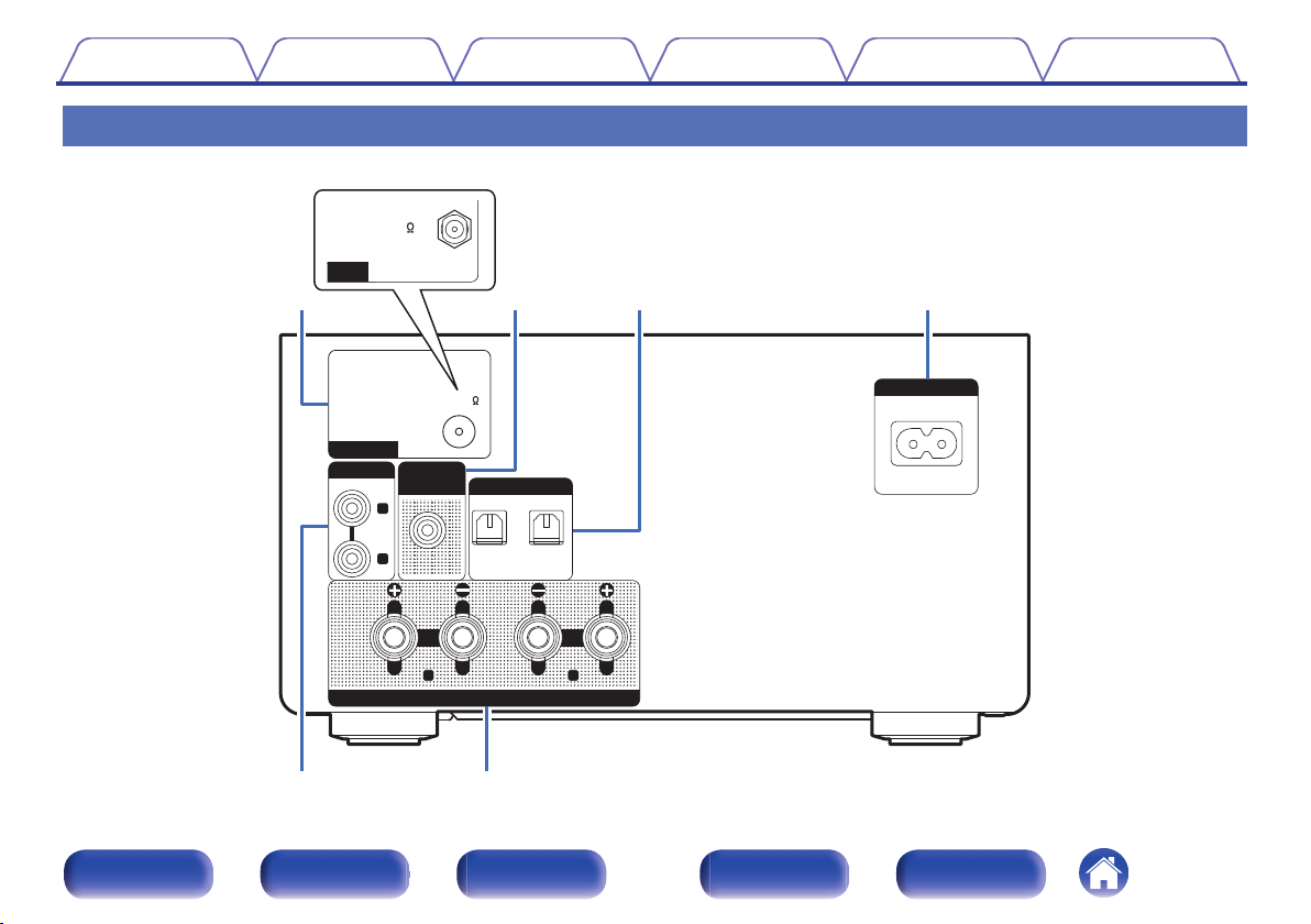
Rear panel
.
R
L
12
OPTICAL
DIGITAL IN
AC IN
R L
ANALOG IN
SUB
WOOFER
OUT
SPEAKERS
FM 75
ANTENNA
t y
RCD-M41DAB
qwe r
DAB/FM 50
NNA
For details, see the next page.
Contents
Connections Playback Settings Tips Appendix
12
Front panel Display Rear panel Remote Index
.
R
L
1
2
OPTICAL
DIGITAL IN
AC IN
R L
ANALOG IN
SUB
WOOFER
OUT
SPEAKERS
FM 75
ANTENNA
t
y
RCD-M41DAB
qwe r
DAB/FM 50
NNA
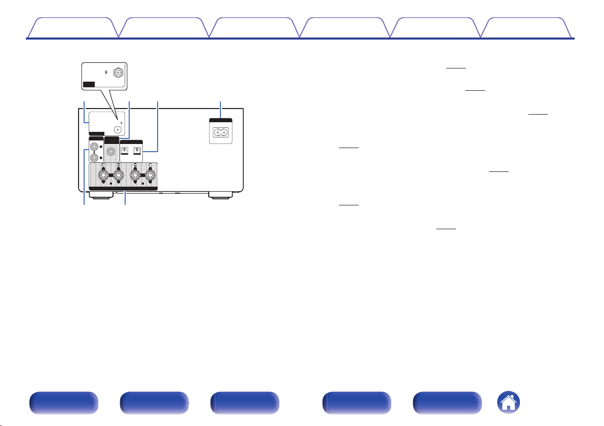
A
FM antenna terminal (ANTENNA) (for RCD-M41 only)
Used to connect FM antenna. (v
p. 21)
DAB/FM antenna terminal (ANTENNA) (for RCD-M41DAB only)
Used to connect DAB/FM antenna. (v p. 21)
B
Subwoofer connector (SUBWOOFER OUT)
Used to connect a subwoofer with a built-in amplifier. (v
p. 19)
C
Digital audio connectors (DIGITAL IN)
Used to connect devices equipped with digital audio connectors.
(v
p. 20)
D
AC inlet (AC IN)
Used to connect the supplied power cord. (v p. 23)
E
Analog audio connectors (ANALOG IN)
Used to connect devices equipped with analog audio connectors.
(v p. 20)
F
Speaker terminals (SPEAKERS)
Used to connect speakers. (v p. 18)
Contents
Connections Playback Settings Tips Appendix
13
Front panel Display Rear panel Remote Index
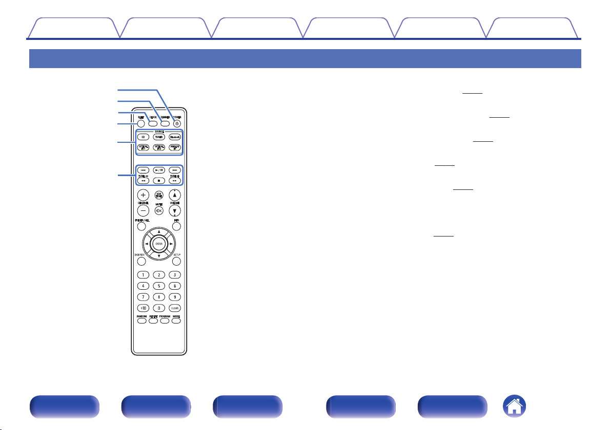
Remote control unit
r
e
w
q
t
y
A
POWER button (X)
This turns the power on/standby. (v p. 25)
B
DIMMER button
Adjust the display brightness of this unit. (v
p. 50)
C
CLOCK button
The current time appear on the unit. (v
p. 49)
D
SLEEP button
This sets the sleep timer. (v
p. 49)
E
Input source select buttons
These select the input source. (v
p. 26)
F
System buttons
These perform playback related operations.
Tuning buttons (TUNE +, –)
These operate the tuner. (v p. 31)
Contents
Connections Playback Settings Tips Appendix
14
Front panel Display Rear panel Remote Index

i
u
Q4
Q1
Q2
Q0
Q3
o
G
Signal transmitter
This transmits signals from the remote control unit. (v
p. 6)
H
CHANNEL buttons (+, –)
This switches between preset channels. (v p. 31)
I
FOLDER/ALL button
This switches the playback range on a data CD. (v
p. 29)
J
MUTE button (:)
This mutes the output audio. (v
p. 26)
K
ENTER button
This determines the selection.
L
Cursor buttons (uio p)
These select items.
M
DAB/RDS button
This configures the DAB/RDS setting. (v
p. 31)
N
Number buttons (0 – 9, +10)
These enter numbers into the unit.
Contents
Connections Playback Settings Tips Appendix
15
Front panel Display Rear panel Remote Index
Q8
Q9
Q7
W0
Q5
Q6
W1
W2
W3
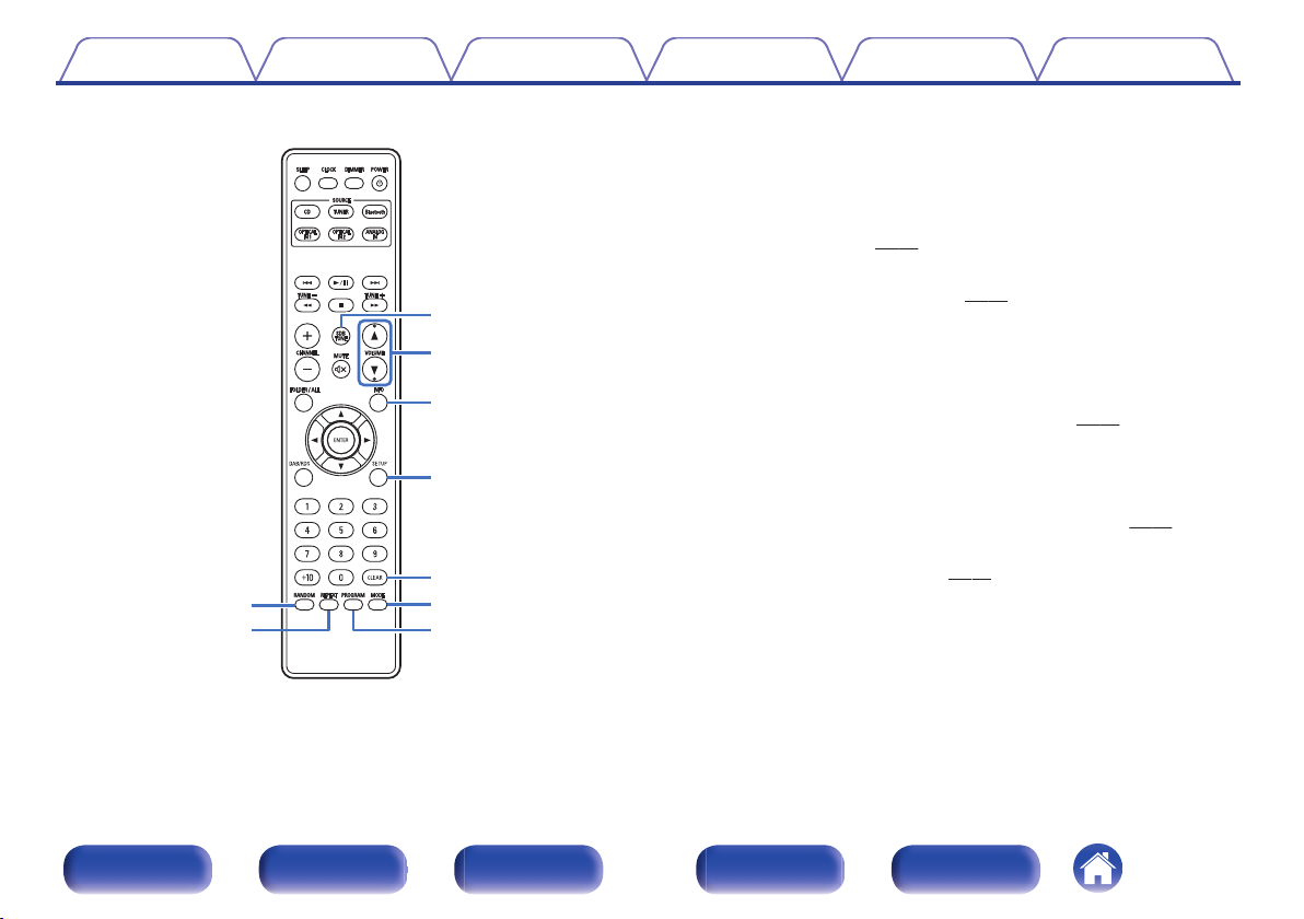
O
RANDOM button
Switches the random playback.
P
REPEAT button
Switches to the repeat playback.
Q
SDB/TONE button
Adjusting the tone. (v
p. 48)
R
VOLUME buttons (df)
These adjust the volume level. (v p. 26)
S
Information button (INFO)
This switches the track information shown in the display during
playback.
T
SETUP button
The setting menu is displayed on the display. (v
p. 52)
U
CLEAR button
This cancels the settings.
V
MODE button
This switches the operation mode for the FM tuning. (v
p. 31)
W
PROGRAM button
This sets program playback. (v p. 28)
Contents
Connections Playback Settings Tips Appendix
16
Front panel Display Rear panel Remote Index

o
Contents
Speaker connection 18
Connecting an analog device 20
Connecting a digital device 20
Connecting a DAB/FM antenna 21
Connecting the power cord 23
NOTE
0
Do not plug in the power cord until all connections have been completed.
0
Do not bundle power cords with connection cables. Doing so can result in noise.
o
Cables used for connections
Provide necessary cables according to the devices you want to connect.
Speaker cable
.
Subwoofer cable
.
Optical cable
.
Audio cable
.
R
L
R
L
Contents Connections Playback Settings Tips Appendix
Connections
17
Front panel Display Rear panel Remote Index
Speaker connection
Here we connect the speakers in the room to this unit.
This section explains how to connect them using typical examples.
NOTE
0
Disconnect this unit’s power plug from the power outlet before connecting the
speakers. Also, turn off the subwoofer.
0
Connect so that the speaker cable core wires do not protrude from the speaker
terminal. The protection circuit may be activated if the core wires touch the rear
panel or if the + and - sides touch each other. (“Protection circuit” (v p. 74))
0
Never touch the speaker terminals while the power cord is connected. Doing so
could result in electric shock.
0
Use speakers with an impedance of 6 – 16 Ω/ohms.
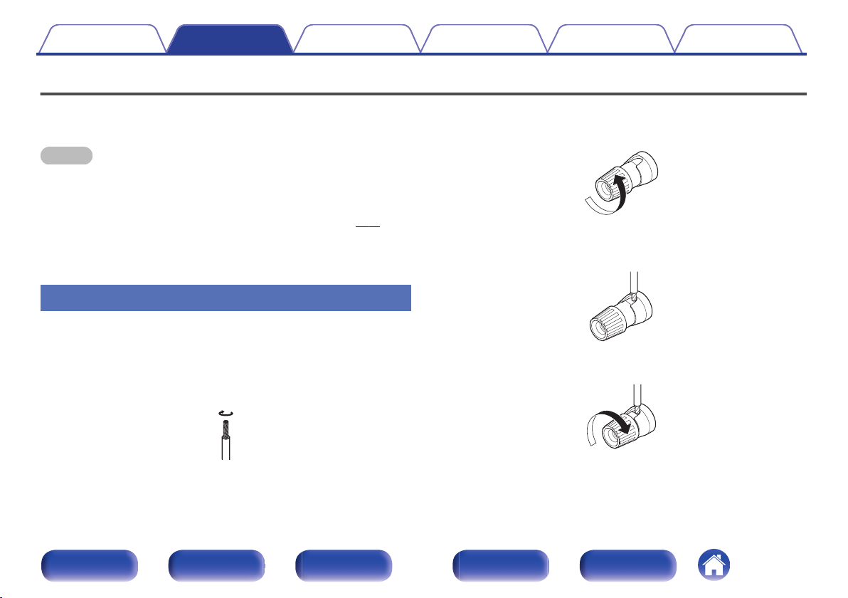
Connecting the speaker cables
Carefully check the left (L) and right (R) channels and + and – polarities on
the speakers being connected to this unit, and be sure to connect the
channels and polarities correctly.
1
Peel off about 10 mm of sheathing from the tip of the
speaker cable, then twist the core wire tightly.
.
2
Turn the speaker terminal counterclockwise to loosen
it.
.
3
Insert the speaker cable’s core wire to the hilt into the
speaker terminal.
.
4
Turn the speaker terminal clockwise to tighten it.
.
Contents
Connections Playback Settings Tips Appendix
18
Front panel Display Rear panel Remote Index
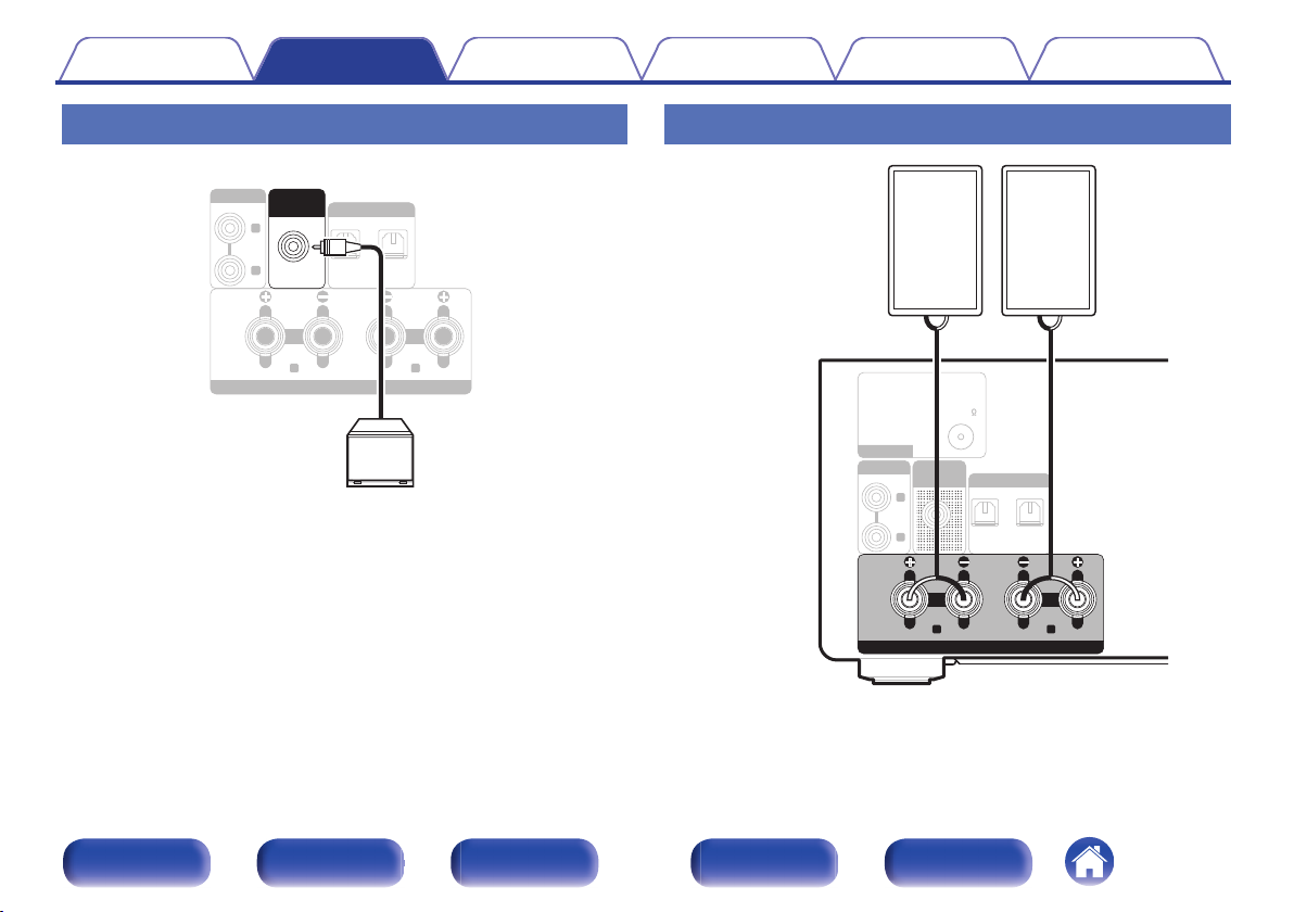
Connecting the subwoofer
Use a subwoofer cable to connect the subwoofer.
.
R
L
12
OPTICAL
DIGITAL IN
R L
ANALOG IN
SUB
WOOFER
OUT
SPEAKERS
Subwoofer
Connecting speakers
.
FM 75
R
L
1
2
OPTICAL
DIGITAL IN
ANTENNA
ANALOG IN
SUB
WOOFER
OUT
R L
SPEAKERS
(R) (L)
wq wq
Speaker
(SC-M41,
sold separately)
Contents
Connections Playback Settings Tips Appendix
19
Front panel Display Rear panel Remote Index
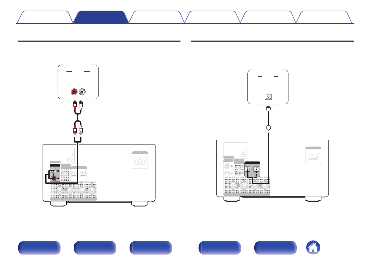
Connecting an analog device
You can connect this unit to various devices with analog audio output.
.
FM 75
1
2
OPTICAL
DIGITAL IN
AC IN
R L
ANTENNA
SUB
WOOFER
OUT
SPEAKERS
R
L
ANALOG IN
AUDIO
LR
OUT
L
R
L
R
AUDIO
Analog
device
Connecting a digital device
You can connect this unit to devices with digital audio output (TV, digital
gear, etc.).
.
FM 75
R
L
AC IN
R L
ANTENNA
ANALOG IN
SUB
WOOFER
OUT
SPEAKERS
1
2
OPTICAL
DIGITAL IN
AUDIO
OPTICAL
OUT
Digital
device
o
Specifications of supported audio formats
See “DIGITAL IN” (v p. 69).
Contents
Connections Playback Settings Tips Appendix
20
Front panel Display Rear panel Remote Index
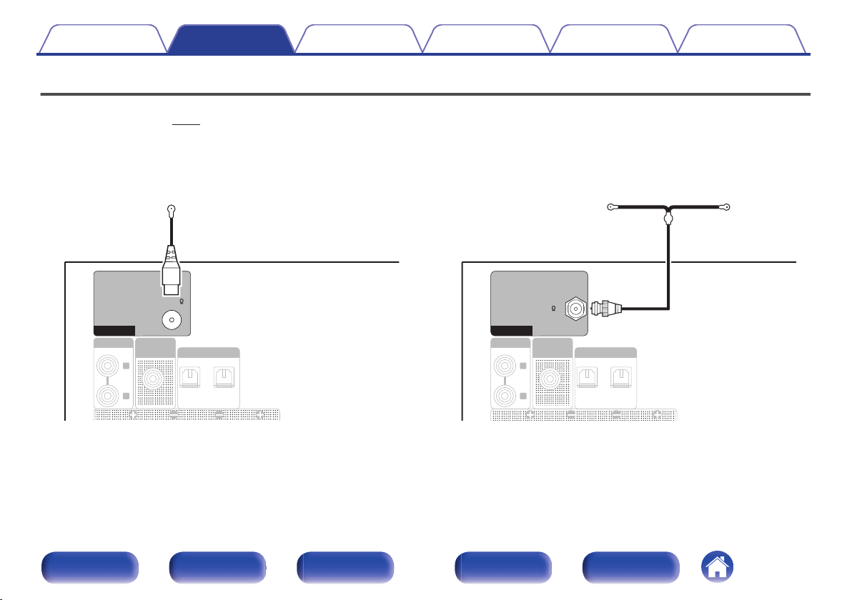
Connecting a DAB/FM antenna
After connecting the antenna and receiving a broadcast signal, fix the antenna with tape in a position where the noise level becomes minimal. “Listening to
DAB/FM broadcasts” (v p. 31)
【for RCD-M41 only】
.
R
L
1
2
OPTICAL
DIGITAL IN
ANALOG IN
SUB
WOOFER
OUT
FM 75
ANTENNA
FM indoor antenna
(supplied)
【for RCD-M41DAB only】
.
R
L
12
OPTICAL
DIGITAL IN
ANALOG IN
SUB
WOOFER
OUT
DAB/FM 50
ANTENNA
DAB/FM indoor antenna
(supplied)
Contents
Connections Playback Settings Tips Appendix
21
Front panel Display Rear panel Remote Index
NOTE
0
For best results with the supplied indoor antenna, orient the antenna along a wall
such that it is stretched out horizontally and parallel to the floor (but above the
floor), and then fasten the two end tabs to the wall. This type of antenna is
directional and best results will be obtained when it is correctly oriented toward the
transmitting location.
0
For example, if the transmission tower is to the north, then the two ends of the
antenna (with the tabs) should be stretched toward west and east.
0
Do not connect two FM antennas simultaneously.
0
If you are unable to receive a good broadcast signal, we recommend installing an
outdoor antenna. For details, inquire at the retail store where you purchased the
unit.
Contents Connections Playback Settings Tips Appendix
22
Front panel Display Rear panel Remote Index
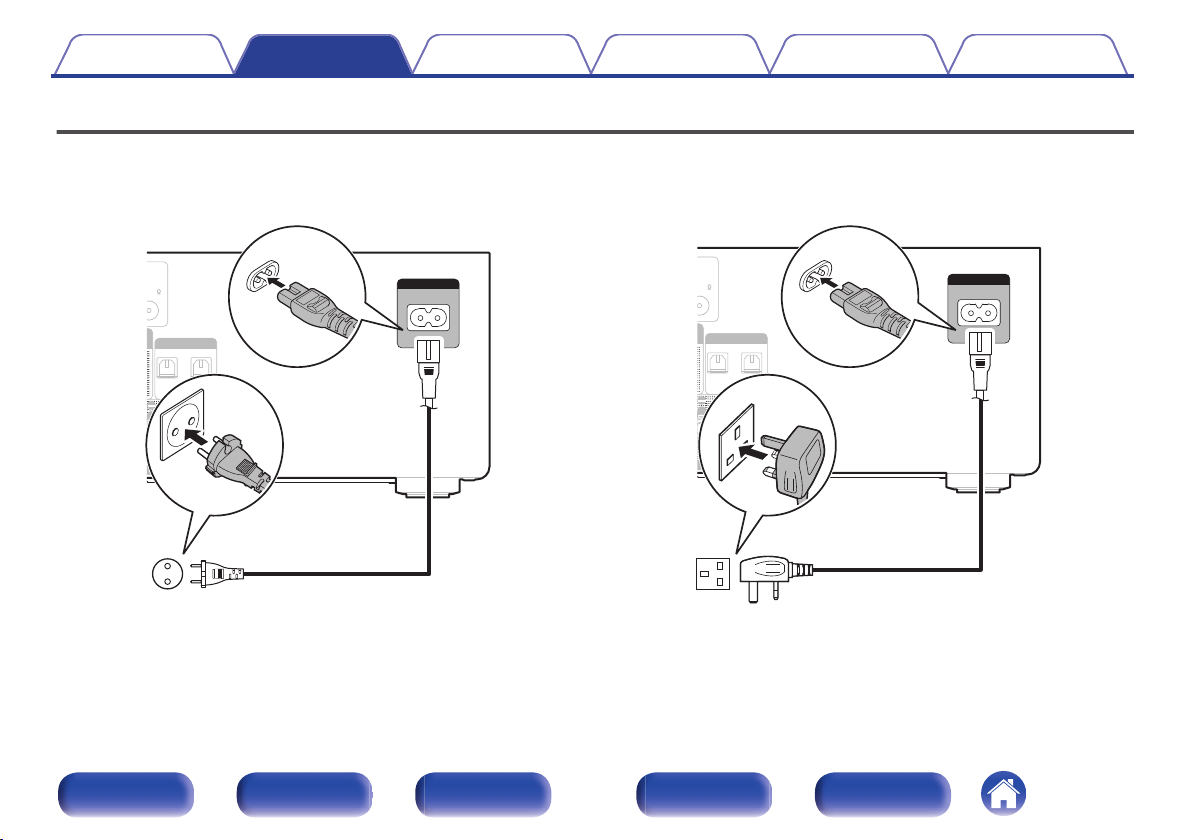
Connecting the power cord
After completing all the connections, insert the power plug into the power outlet.
【for continental】
.
75
12
OPTICAL
DIGITAL IN
L
AKERS
AC IN
Power cord
(supplied)
To household power outlet
(AC 230 V, 50/60 Hz)
【for UK】
.
75
1
2
OPTICAL
DIGITAL IN
L
AKERS
AC IN
Power cord
(supplied)
To household power outlet
(AC 230 V, 50/60 Hz)
Contents
Connections Playback Settings Tips Appendix
23
Front panel Display Rear panel Remote Index
o
Contents
Basic operation
Turning the power on 25
Switching the power to standby 25
Selecting the input source 26
Adjusting the volume 26
Turning off the sound temporarily (Muting) 26
Playback a device
Playing CDs 27
Playing DATA CDs 29
Listening to DAB/FM broadcasts 31
Listening to music on a Bluetooth device 41
Listening to DIGITAL IN 45
Listening to ANALOG IN 46
Other functions
Convenience functions 47
Contents Connections Playback Settings Tips Appendix
Playback
24
Front panel Display Rear panel Remote Index
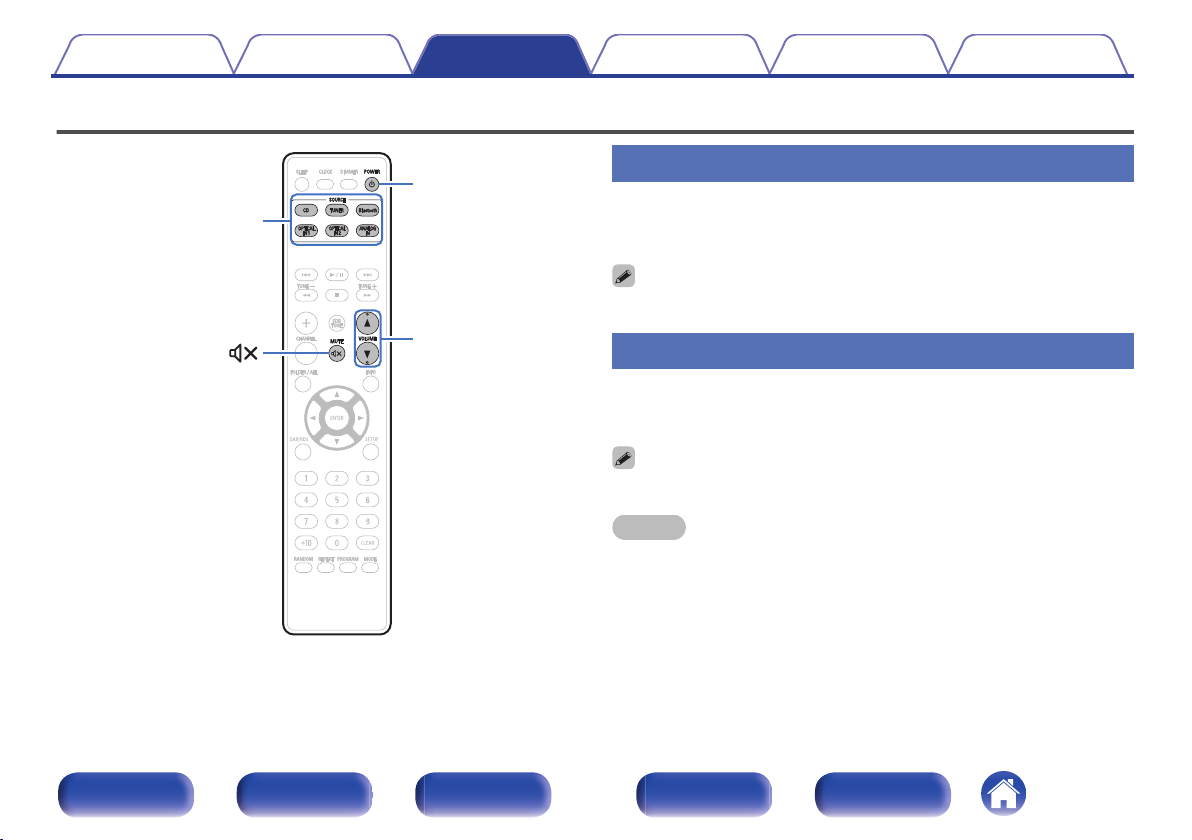
Basic operation
.
Input source
select buttons
POWER
X
VOLUME
df
MUTE
Turning the power on
1
Press POWER X to turn on power to the unit.
The power indicator lights green.
0
You can also press X on the main unit to turn on power from standby mode.
Switching the power to standby
1
Press POWER X.
The unit switches to standby mode.
0
You can also switch the power to standby by pressing X on the main unit.
NOTE
0
Power continues to be supplied to some of the circuitry even when the power is in
the standby mode. When leaving home for long periods of time or when going on
vacation, unplug the power cord from the power outlet.
Contents Connections Playback Settings Tips Appendix
25
Front panel Display Rear panel Remote Index
 Loading...