

Denon DN-X900, ACD-46 Service Manual
Ver. 3
Please refer to the
MODIFICATION NOTICE.
SERVICE MANUAL
MODEL JP E3 E2 EK K2A E1C E1K EUT
DN-X900
ACD-46
33
DJ MIXER
MODEL JP E3 E2 EK K2A E1C E1K EUT
33
ROTARY FADER
注 意
サービスをおこなう前に、このサービスマニュアル
を必ずお読みください。
本機は、火災、感電、けがなどに対する安全性を確
保するために、さまざまな配慮をおこなっており、
また法的には「電気用品安全法」にもとづき、所定
の許可を得て製造されております。
従ってサービスをおこなう際は、これらの安全性が
維持されるよう、このサービスマニュアルに記載さ
れている注意事項を必ずお守りください。
For purposes of improvement, specifi cations and
•
design are subject to change without notice.
Please use this service manual with referring to the
•
operating instructions without fail.
Some illustrations using in this service manual are
•
slightly different from the actual set.
D&M Holdings Inc.
S0184-1V02DM/DG1011
Copyright 2010 D&M Holdings Inc. All rights reserved.
WARNING: Violators will be prosecuted to the maximum extent possible.
・ 本機の仕様は性能改良のため、予告なく変更するこ
とがあります。
・ 補修用性能部品の保有期間は、製造打切後 8年です。
・ 修理の際は、必ず取扱説明書を参照の上、作業を行っ
てください。
・ 本文中に使用しているイラストは、説明の都合上現
物と多少異なる場合があります。
SAFETY PRECAUTIONS
The following check should be performed for the continued protection of the customer and service technician.
LEAKAGE CURRENT CHECK
Before returning the unit to the customer, make sure you make either (1) a leakage current check or (2) a line to chassis
resistance check. If the leakage current exceeds 0.5 milliamps, or if the resistance from chassis to either side of the power
cord is less than 460 kohms, the unit is defective.
DN-X900 / ACD-46
CAUTION
Please heed the points listed below during servicing and inspection.
◎ Heed the cautions!
Spots requiring particular attention when servicing, such as
the cabinet, parts, chassis, etc., have cautions indicated on
labels or seals. Be sure to heed these cautions and the cautions indicated in the handling instructions.
◎ Caution concerning electric shock!
(1) An AC voltage is impressed on this set, so touching inter-
nal metal parts when the set is energized could cause
electric shock. Take care to avoid electric shock, by for example using an isolating transformer and gloves when
servicing while the set is energized, unplugging the power
cord when replacing parts, etc.
(2)There are high voltage parts inside. Handle with extra care
when the set is energized.
◎
Caution concerning disassembly and assembly!
Though great care is taken when manufacturing parts from
sheet metal, there may in some rare cases be burrs on the
edges of parts which could cause injury if fingers are moved
across them. Use gloves to protect your hands.
◎ Only use designated parts!
The set's parts have specific safety properties (fire resistance, voltage resistance, etc.). For replacement parts, be
sure to use parts which have the same properties. In particular, for the important safety parts that are marked ! on wiring
diagrams and parts lists, be sure to use the designated parts.
◎ Be sure to mount parts and arrange the
wires as they were originally!
For safety reasons, some parts use tape, tubes or other insulating materials, and some parts are mounted away from the
surface of printed circuit boards. Care is also taken with the
positions of the wires inside and clamps are used to keep
wires away from heating and high voltage parts, so be sure to
set everything back as it was originally.
◎ Inspect for safety after servicing!
Check that all screws, parts and wires removed or disconnected for servicing have been put back in their original positions, inspect that no parts around the area that has been
serviced have been negatively affected, conduct an insulation
check on the external metal connectors and between the
blades of the power plug, and otherwise check that safety is
ensured.
(Insulation check procedure)
Unplug the power cord from the power outlet, disconnect the
antenna, plugs, etc., and turn the power switch on. Using a
500V insulation resistance tester, check that the insulation resistance between the terminals of the power plug and the externally exposed metal parts (antenna terminal, headphones
terminal, microphone terminal, input terminal, etc.) is 1MΩ or
greater. If it is less, the set must be inspected and repaired.
CAUTION
Many of the electric and structural parts used in the set have
special safety properties. In most cases these properties are
difficult to distinguish by sight, and using replacement parts
with higher ratings (rated power and withstand voltage) does
not necessarily guarantee that safety performance will be preserved. Parts with safety properties are indicated as shown
below on the wiring diagrams and parts lists is this service
manual. Be sure to replace them with parts with the designated part number.
(1) Schematic diagrams ... Indicated by the ! mark.
(2) Parts lists ... Indicated by the ! mark.
Concerning important safety parts
Using parts other than the designated parts
could result in electric shock, fires or other
dangerous situations.
注 意
サービス、点検時にはつぎのことにご注意願います。
◎注意事項をお守りください!
サービスのとき特に注意を必要とする個所についてはキャ
ビネット、部品、シャーシなどにラベルや捺印で注意事項を
表示しています。これらの注意書きおよび取扱説明書などの
注意事項を必ずお守りください。
◎感電に注意!
(1) このセットは、交流電圧が印加されていますので通電時
に内部金属部に触れると感電することがあります。従っ
て通電サービス時には、絶縁トランスの使用や手袋の着
用、部品交換には、電源プラグを抜くなどして感電にご
注意ください。
(2) 内部には高電圧の部分がありますので、通電時の取扱に
は十分ご注意ください。
◎分解、組み立て作業時のご注意!
板金部品の端面の『バリ』は、部品製造時に充分管理をして
おりますが、板金端面は鋭利となっている箇所が有りますの
で、部品端面に触れたまま指を動かすとまれに怪我をする場
合がありますので十分注意して作業して下さい。手の保護の
ために手袋を着用してください。
◎指定部品の使用!
セットの部品は難燃性や耐電圧など安全上の特性を持った
ものとなっています。従って交換部品は、使用されていたも
のと同じ特性の部品を使用してください。特に配線図、部品
!印で指定されている安全上重要な部品は必ず指定の
表に
ものをご使用ください。
◎部品の取付けや配線の引きまわしは、
元どおりに!
安全上、テープやチューブなどの絶縁材料を使用したり、プ
リント基板から浮かして取付けた部品があります。また内部
配線は引きまわしやクランパーによって発熱部品や高圧部
品に接近しないように配慮されていますので、これらは必ず
元どおりにしてください。
◎サービス後は安全点検を!
サービスのために取り外したねじ、部品、配線などが元どお
りになっているか、またサービスした個所の周辺を劣化させ
てしまったところがないかなどを点検し、外部金属端子部
と、電源プラグの刃の間の絶縁チェックをおこなうなど、安
全性が確保されていることを確認してください。
(絶縁チェックの方法)
電源コンセントから電源プラグを抜き、アンテナやプラグな
どを外し、電源スイッチを入れます。500V 絶縁抵抗計を用
いて、電源プラグのそれぞれの端子と外部露出金属部[アン
テナ端子、ヘッドホン端子マイク端子、入力端子など]との
間で、絶縁抵抗値が1 MΩ 以上であること、この値以下の
ときはセットの点検修理が必要です。
注 意
本機に使用している多くの電気部品、および機構部品は安全
上、特別な特性を持っています。この特性はほとんどの場合、
外観では判別つきにくく、またもとの部品より高い定格(定
格電力、耐圧)を持ったものを使用しても安全性が維持され
るとは、限りません。安全上の特性を持った部品は、この
サービスマニュアルの配線図、部品表につぎのように表示し
ていますので必ず指定されている部品番号のものを使用願
います。
(1) 配線図…
(2) 部品表…
安全上重要な部品について
!マークで表示しています。
!マークで表示しています。
指定された部品と異なるものを使用した場合に
は、感電、火災などの危険を生じる恐れがあり
ます。
2
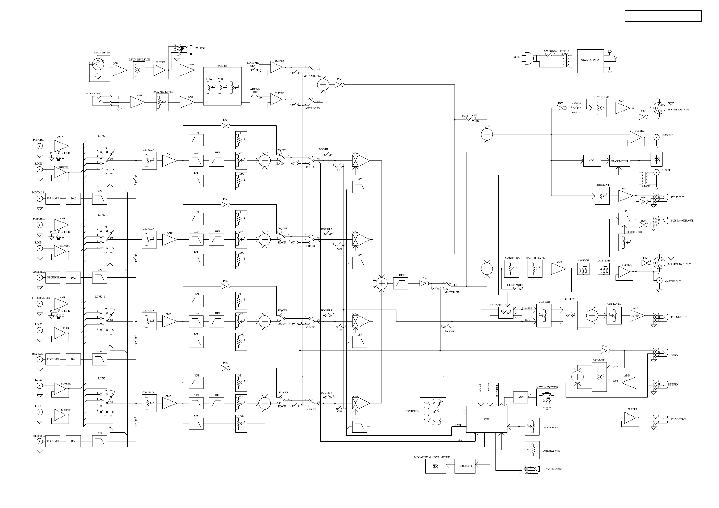
BLOCK DIAGRAMS
DN-X900 / ACD-46
3
SEMICONDUCTORS
Only major semiconductors are shown, general semiconductors etc. are omitted to list.
主な半導体を記載しています。汎用の半導体は記載を省略しています。
IC’s
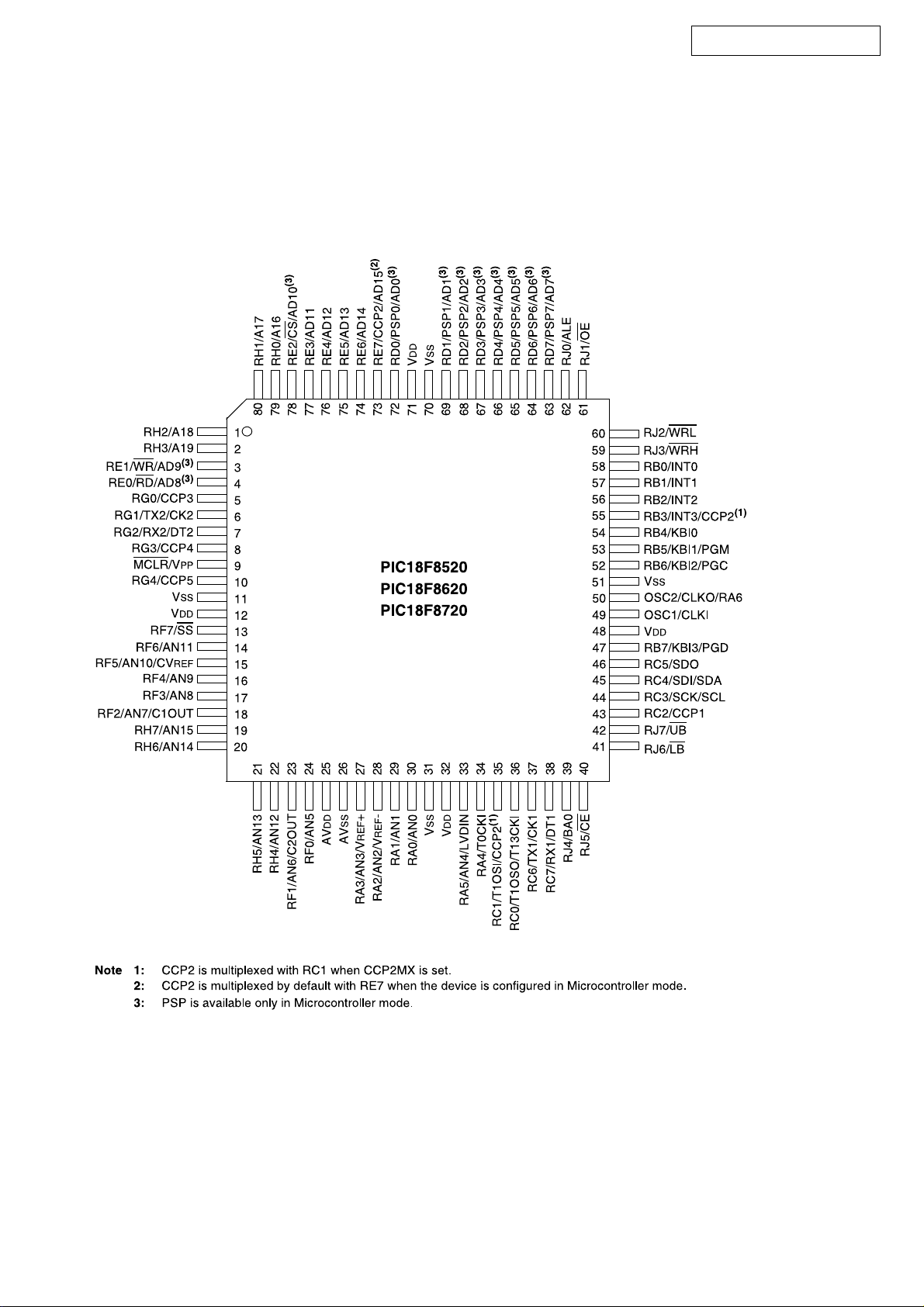
PIC18F8520-I/PTG (IC801) CPU P.W.B.
DN-X900 / ACD-46
4
PIC18F8520-I/PTG Terminal Function
Pin No. Pin Name I/O Function
1 OE O 74HC595CONTROLPIN
2 DS O 74HC595CONTROLPIN
3 CHFS I CHFADERSTARTSWINPUT
4 CFFSA I CROSSFADERSTARTASWINPUT
5 PWM1 O CH1VocalCONTROL
6 CFFSB I CROSSFADERSTARTBSWINPUT
7 ASSIGN4A I CH4CROSSFADERASSIGN(A,POST,B)
8 PWM2 O CH2VocalCONTROL
10 PWM3 O CH3VocalCONTROL
13 ASSIGN4B I CH4CROSSFADERASSIGN(A,POST,B)
14 CF I CROSSFADERVRA/DIN
15 INSEL4 I CH4INPUTASSIGNA/DIN
16 CFC I CROSSFADERCONTOURVRA/DIN
17 INSEL1 I CH1INPUTASSIGNA/DIN
18 INSEL2 I CH2INPUTASSIGNA/DIN
19 INSEL3 I CH3INPUTASSIGNA/DIN
20 LML I MASTERLCHLevelMeterA/DIN
21 LMR I MASTERRCHLevelMeterA/DIN
22 LM1 I CH1LevelMeterA/DIN
23 LM2 I CH2LevelMeterA/DIN
24 LM3 I CH3LevelMeterA/DIN
27 LM4 I CH4LevelMeterA/DIN
28 F1 I CH1FADERVRA/DIN
29 F2 I CH2FADERVRA/DIN
30 F3 I CH3FADERVRA/DIN
33 F4 I CH4FADERVRA/DIN
34 CE1-1 O LC78211,LC78212,LC78213CONTROLPIN
35 PWM4 O CH4VocalCONTROL
36 CE2-2 O LC78211,LC78212,LC78213CONTROLPIN
37 DI-1 O LC78211,LC78212,LC78213CONTROLPIN
38 CL-1 O LC78211,LC78212,LC78213CONTROLPIN
39 -24 O LevelMeterLEDCONTROL
40 -10 O LevelMeterLEDCONTROL
41 -7 O LevelMeterLEDCONTROL
42 -5 O LevelMeterLEDCONTROL
43 -3 O LevelMeterLEDCONTROL
44 -1 O LevelMeterLEDCONTROL
45 0 O LevelMeterLEDCONTROL
46 1 O LevelMeterLEDCONTROL
47 3 O LevelMeterLEDCONTROL
52 5 O LevelMeterLEDCONTROL
53 8 O LevelMeterLEDCONTROL
54 12 O LevelMeterLEDCONTROL
55 CLMR O LevelMeterLEDCONTROL
56 CLML O LevelMeterLEDCONTROL
57 CLM4 O LevelMeterLEDCONTROL
58 CLM3 O LevelMeterLEDCONTROL
59 CLM2 O LevelMeterLEDCONTROL
60 CLM1 O LevelMeterLEDCONTROL
61 INT I CS8405ACONTROLPIN
62 CDOUT I ICDATAOUT
63 CDIN O ICDATAIN
64 CCLK O ICCLK
65 JDET I EFFECTSEND/RETURNINPUTSW
66 /CS O CS8405ASELECTIONPIN
67 PC4B O LINE8FADERCONTROLOUTPUT
68 PC4A O LINE8FADERCONTROLOUTPUT
69 PC3B O LINE6FADERCONTROLOUTPUT
72 PC3A O LINE6FADERCONTROLOUTPUT
73 PC2B O LINE4FADERCONTROLOUTPUT
74 PC2A O LINE4FADERCONTROLOUTPUT
75 PC1B O LINE2FADERCONTROLOUTPUT
76 PC1A O LINE2FADERCONTROLOUTPUT
77 /CSAD O ADC0838SELECTIONPIN
79 SHCP O 74HC595CONTROLPIN
80 STCP O 74HC595CONTROLPIN
DN-X900 / ACD-46
5
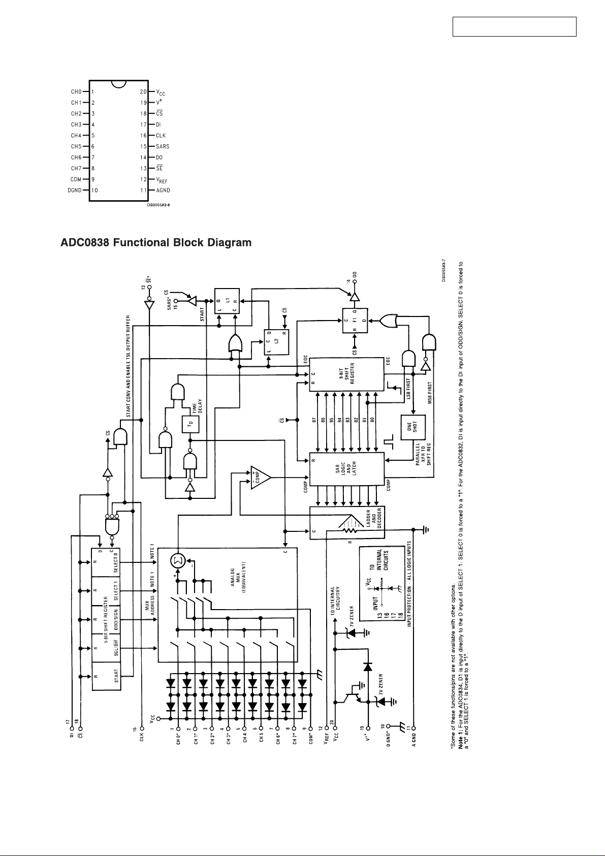
ADC0838CCWM (IC 802) MIXER P.W.B.
DN-X900 / ACD-46
6
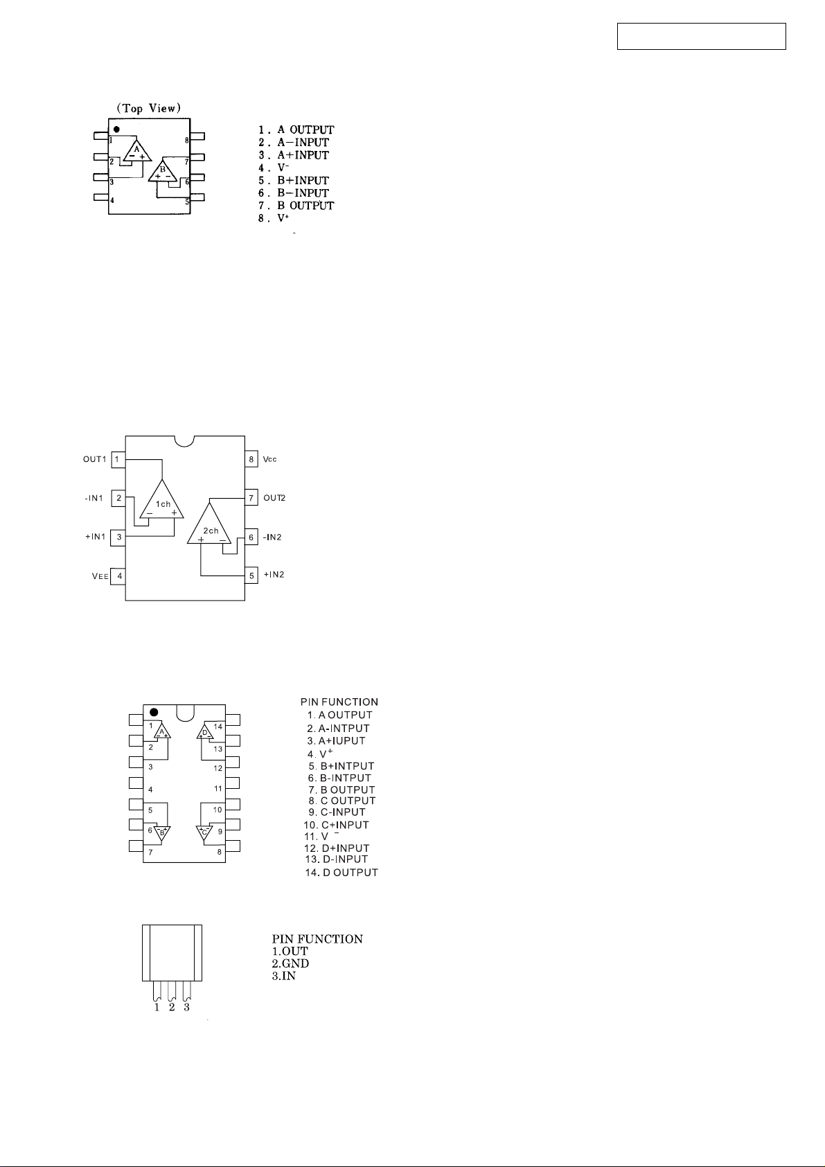
NJM-4556AD (IC617) MIXER P.W.B.
BA15218F (IC 701) OUTPUT P.W.B.
(IC 704) BOOTH P.W.B.
(IC 603,901,902,908) POWER P.W.B.
(IC 104,204,304,404,501,502,606-609, 609,611,616) MIXER P.W.B.
(IC 503,601-603,605,610,612,613) CPU P.W.B.
DN-X900 / ACD-46
NJM2058V (IC 504) CPU P.W.B.
NJM78L004 (IC 108) CPU P.W.B.
7
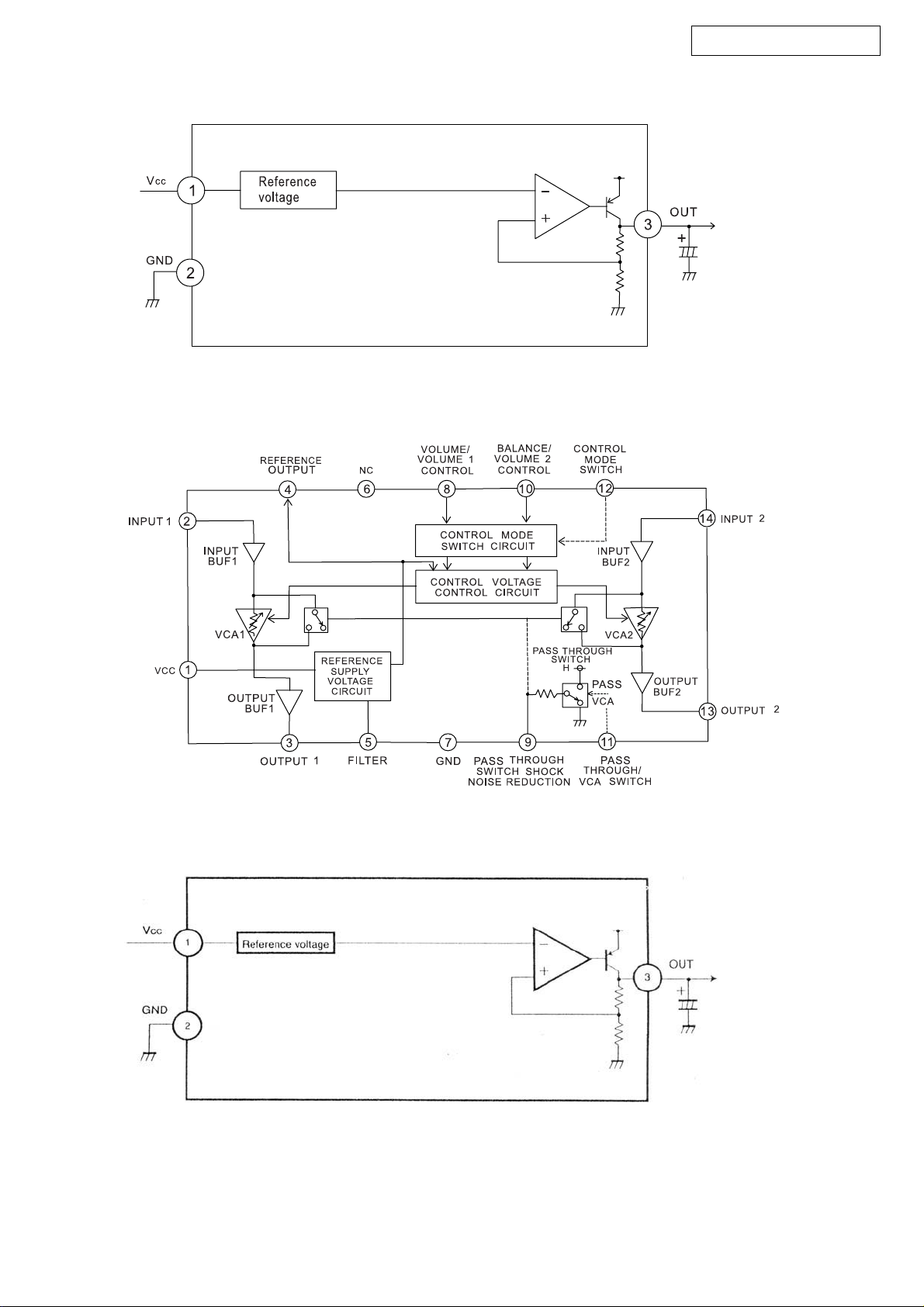
BA05T (IC 03) POWER P.W.B.
M51132L (IC 106,206,306,406) CPU P.W.B.
DN-X900 / ACD-46
BA033FP T0252-3 (IC 805) CPU P.W.B.
8
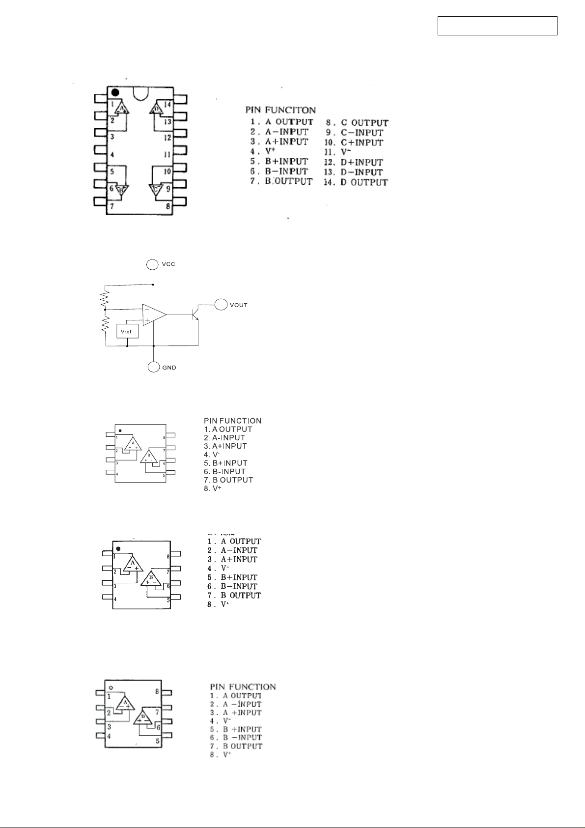
NJM2060V (IC 101-103,201-203,301-303,401-403) MIXER P.W.B.
BD4745G (IC 04) POWER P.W.B.
DN-X900 / ACD-46
NJM4558M-TE3 (IC 107,109,209,307,309,409) CPU P.W.B.
NJM2068M (IC 510) OUTPUT P.W.B.
(IC 511) POWER P.W.B.
NJM4580M (IC 114,115,214,215,314,315,414,415) OUTPUT P.W.B.
NJM4580D (IC 703,705) OUTPUT P.W.B.
9
DN-X900 / ACD-46
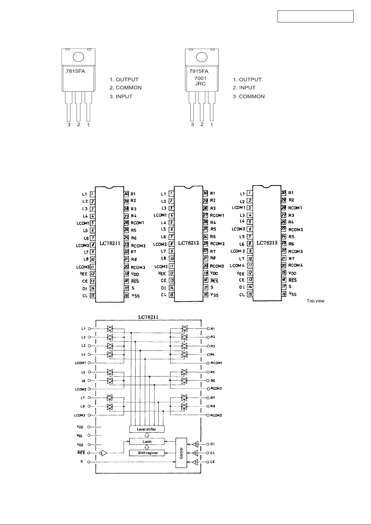
NJM7815FA (IC 01) POWER P.W.B. NJM7915FA (IC 02) POWER P.W.B.
LC78211 (IC 116,216,316,416) OUTPUT P.W.B.
LC78212 (IC 105,205,305,405) CPU P.W.B.
LC78213 (IC 117) OUTPUT P.W.B.
(IC 509,604,615) CPU P.W.B.
10

CS8415A (IC 111,211,311,411) POWER P.W.B.
DN-X900 / ACD-46
CS8405A (IC 906) POWER P.W.B.
11
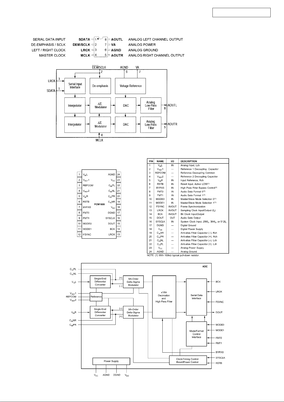
CS4334 (IC 112,212,312,412) POWER P.W.B.
PCM1800E (IC 904) POWER P.W.B.
DN-X900 / ACD-46
12
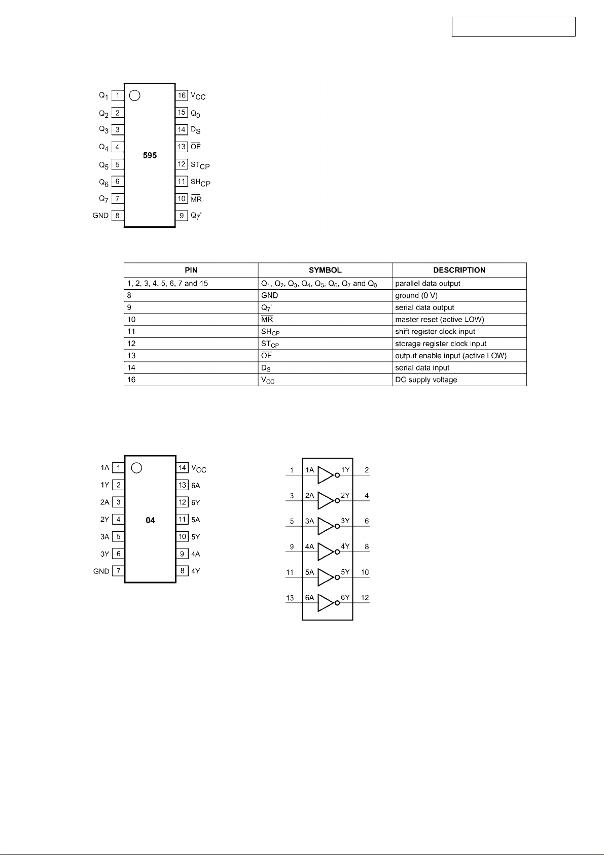
74AHC595D (IC 803,804) MIXER P.W.B.
DN-X900 / ACD-46
74AHC04 (IC 905) POWER P.W.B.
13
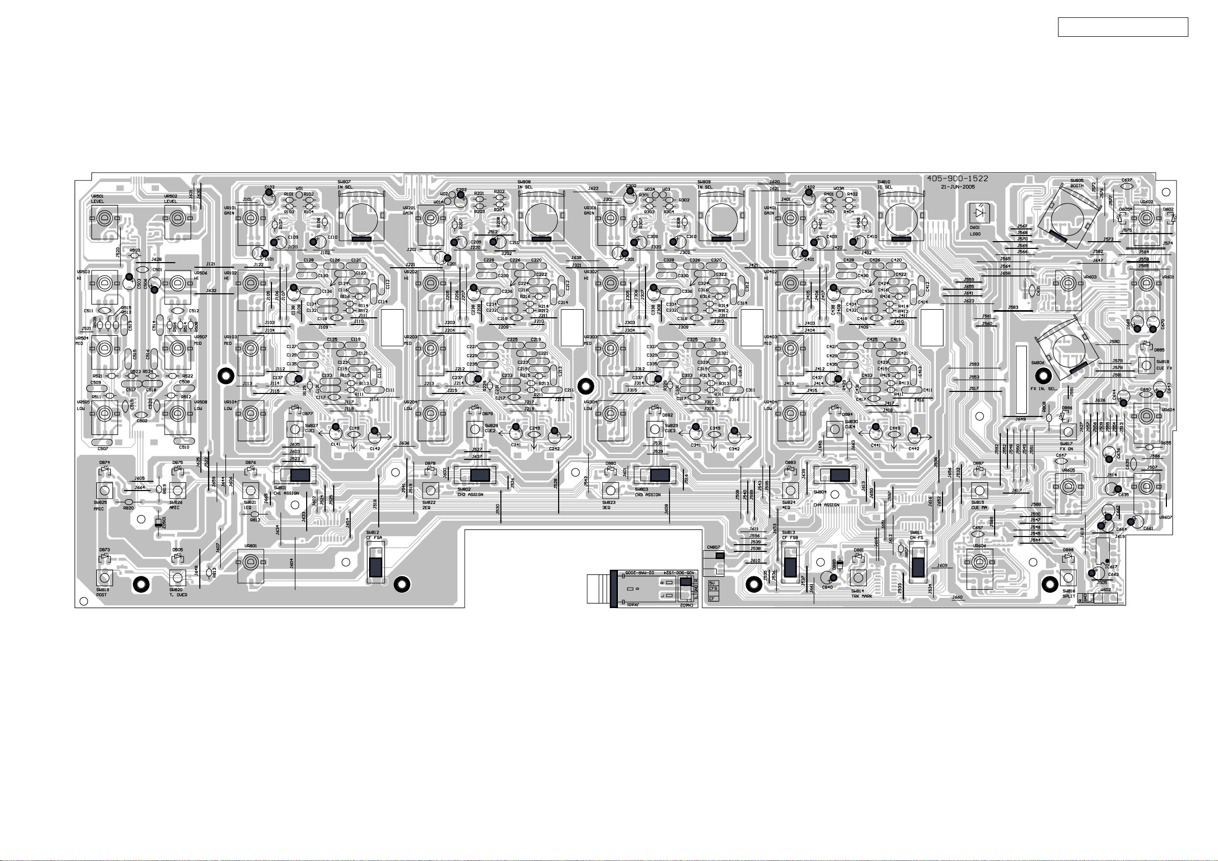
PRINTED WIRING BOARDS (DN-X900 & ACD-46)
MIXER & HEADPHONE Board (1/2)
DN-X900 / ACD-46
14
COMPONENT SIDE
 Loading...