

Page 1

Digital Controller and Media Player
DN-SC2900
Owner’s Manual
Page 2

CAUTION
DO NOT OPEN
RISK OF ELECTRIC SHOCK
CAUTION:
TO REDUCE THE RISK OF ELECTRIC SHOCK, DO NOT REMOVE COVER (OR BACK).
NO USER-SERVICEABLE PARTS INSIDE. REFER SERVICING TO QUALIFIED SERVICE
PERSONNEL.
The lightning flash with arrowhead symbol, within an equilateral triangle, is intended to
alert the user to the presence of uninsulated “dangerous voltage” within the product’s
enclosure that may be of sufficient magnitude to constitute a risk of electric shock to
persons.
The exclamation point within an equilateral triangle is intended to alert the user to
the presence of important operating and maintenance (servicing) instructions in the
literature accompanying the appliance.
IMPORTANT TO SAFETY
WARNING:
To reduce the risk of fire and electric shock, this apparatus should not be exposed
to rain or moisture and objects filled with liquids, such as vases, should not be
placed on this apparatus.
CAUTION:
USE OF CONTROLS OR ADJUSTMENTS OR PERFORMANCE OF PROCEDURES
OTHER THAN THOSE SPECIFIED HEREIN MAY RESULT IN HAZARDOUS RADIATION
EXPOSURE.
THIS PRODUCT SHOULD NOT BE ADJUSTED OR REPAIRED BY ANYONE EXCEPT
PROPERLY QUALIFIED SERVICE PERSONNEL.
IMPORTANT SAFETY INSTRUCTIONS
READ BEFORE OPERATING EQUIPMENT
This product was designed and manufactured to meet strict quality and safety standards. There are, however,
some installation and operation precautions which you should be particularly aware of.
1. Read these instructions.
2. Keep these instructions.
3. Heed all warnings.
4. Follow all instructions.
5. Do not use this apparatus near water.
6. Clean only with dry cloth.
7. Do not block any ventilation openings. Install in accordance with the manufacturer’s instructions.
8. Do not install near any heat sources such as radiators, heat registers, stoves, or other apparatus
(including amplifiers) that produce heat.
9. Do not defeat the safety purpose of the polarized or grounding-type plug. A polarized plug has two
blades with one wider than the other. A grounding type plug has two blades and a third grounding
prong. The wide blade or the third prong are provided for your safety. If the provided plug does not fit
into your outlet, consult an electrician for replacement of the obsolete outlet.
10. Protect the power cord from being walked on or pinched particularly at plugs, convenience
receptacles, and the point where they exit from the apparatus.
11.
Only use attachments/accessories specified by the manufacturer.
12. Use only with the cart, stand, tripod, bracket, or table specified by the
manufacturer, or sold with the apparatus. When a cart is used, use caution
when moving the cart/apparatus combination to avoid injury from tip-over.
13. Unplug this apparatus during lightning storms or when unused for long
periods of time.
14. Refer all servicing to qualified service personnel. Servicing is required when the apparatus has been
damaged in any way, such as power-supply cord or plug is damaged, liquid has been spilled or objects
have fallen into the apparatus, the apparatus has been exposed to rain or moisture, does not operate
normally, or has been dropped.
I
Page 3

n Laser Class
(IEC60825-1:2007)
CLASS 1 LASER PRODUCT
LUOKAN 1 LASERLAITE
KLASS 1 LASERAPPARAT
ADVARSEL: USYNLIG LASERSTRÅLING VED ÅBNING, NÅR
SIKKERHEDSAFBRYDERE ER UDE AF FUNKTION.
UNDGÅ UDSAETTELSE FOR STRÅLING.
VAROITUS! LAITTEEN KÄYTTÄMINEN MUULLA KUIN TÄSSÄ
KÄYTTÖOHJEESSA MAINITULLA TAVALLA SAATTAA
ALTISTAA KÄYTTÄJÄN TURVALLISUUSLUOKAN 1
YLITTÄVÄLLE NÄKYMÄMTTÖMÄLLE LASERSÄTEILYLLE.
VARNING: OM APPARATEN ANVÄNDS PÅ ANNAT SÄTT ÄN I DENNA
BRUKSANVISNING SPECIFICERATS, KAN ANVÄNDAREN
UTSÄTTAS FÖR OSYNLIG LASERSTRÅLNING SOM
ÖVERSKRIDER GRÄNSEN FÖR LASERKLASS 1.
ATTENZIONE: QUESTO APPARECCHIO E’ DOTATO DI DISPOSITIVO OTTICO CON RAGGIO LASER.
L’USO IMPROPRIO DELL’APPARECCHIO PUO’ CAUSARE PERICOLOSE ESPOSIZIONI A RADIAZIONI!
,,
CLASS 1
LASER
PRODUCT
CAUTION
1. Handle the power supply cord carefully
,
,
Do not damage or deform the power supply cord. If it is damaged or deformed, it may cause electric
shock or malfunction when used. When removing from wall outlet, be sure to remove by holding the
plug attachment and not by pulling the cord.
2. Do not open the rear cover
In order to prevent electric shock, do not open the top cover.
If problems occur, contact your DENON DEALER.
3. Do not place anything inside
Do not place metal objects or spill liquid inside the system.
Electric shock or malfunction may result.
Please, record and retain the Model name and serial number of your set shown on the rating label.
Model No. DN-SC2900
Serial No.
II
Page 4

n NOTES ON USE/HINWEISE ZUM GEBRAUCH/OBSERVATIONS RELATIVES A L’UTILISATION/
NOTE SULL’USO/NOTAS SOBRE EL USO/ALVORENS TE GEBRUIKEN/OBSERVERA
WARNINGS WARNHINWEISE AVERTISSEMENTS AVVERTENZE ADVERTENCIAS WAARSCHUWINGEN VARNINGAR
•Handle the power cord carefully.
Hold the plug when unplugging
the cord.
•Keep the unit free from
moisture, water, and dust.
•Unplug the power cord when
not using the unit for long
periods of time.
•Do not obstruct the ventilation
holes.
•Do not let foreign objects into
the unit.
•Do not let insecticides,
benzene, and thinner come in
contact with the unit.
•Never disassemble or modify
the unit in any way.
•Ventilation should not be
impeded by covering the
ventilation openings with
items, such as newspapers,
tablecloths or curtains.
•Naked flame sources such as
lighted candles should not be
placed on the unit.
•Do not expose the unit to
dripping or splashing fluids.
•Do not place objects filled with
liquids, such as vases, on the
unit.
•Do not handle the mains cord
with wet hands.
•When the switch is in the OFF
position, the equipment is not
completely switched off from
MAINS.
•The equipment shall be
installed near the power supply
so that the power supply is
easily accessible.
•Gehen Sie vorsichtig mit dem
Netzkabel um.
Halten Sie das Kabel am
Stecker, wenn Sie den Stecker
herausziehen.
•Halten Sie das Gerät von
Feuchtigkeit, Wasser und Staub
fern.
•Decken Sie den Lüftungsbereich
nicht ab.
•Wenn das Gerät längere Zeit
nicht verwendet werden soll,
trennen Sie das Netzkabel vom
Netzstecker.
•Lassen Sie keine fremden
Gegenstände in das Gerät
kommen.
•Lassen Sie das Gerät nicht
mit Insektiziden, Benzin oder
Verdünnungsmitteln in Berührung
kommen.
•Versuchen Sie niemals das Gerät
auseinander zu nehmen oder zu
verändern.
•Die Belüftung sollte auf keinen
Fall durch das Abdecken der
Belüftungsöffnungen durch
Gegenstände wie beispielsweise
Zeitungen, Tischtücher, Vorhänge
o. Ä. behindert werden.
•Auf dem Gerät sollten keinerlei
direkte Feuerquellen wie
beispielsweise angezündete
Kerzen aufgestellt werden.
•Das Gerät sollte keiner tropfenden
oder spritzenden Flüssigkeit
ausgesetzt werden.
•Auf dem Gerät sollten keine mit
Flüssigkeit gefüllten Behälter wie
beispielsweise Vasen aufgestellt
werden.
•Das Netzkabel nicht mit feuchten
oder nassen Händen anfassen.
•Wenn der Schalter ausgeschaltet
ist (OFF-Position), ist das Gerät
nicht vollständig vom Stromnetz
(MAINS) abgetrennt.
•Das Gerät sollte in der Nähe einer
Netzsteckdose aufgestellt werden,
damit es leicht an das Stromnetz
angeschlossen werden kann.
•Manipuler le cordon
d’alimentation avec précaution.
Tenir la prise lors du
débranchement du cordon.
•Protéger l’appareil contre
l’humidité, l’eau et la poussière.
•Débrancher le cordon
d’alimentation lorsque l’appareil
n’est pas utilisé pendant de
longues périodes.
•Ne pas obstruer les trous
d’aération.
•Ne pas laisser des objets
étrangers dans l’appareil.
•Ne pas mettre en contact des
insecticides, du benzène et un
diluant avec l’appareil.
•Ne jamais démonter ou
modifier l’appareil d’une
manière ou d’une autre.
•Ne pas recouvrir les orifices
de ventilation avec des objets
tels que des journaux, nappes
ou rideaux. Cela entraverait la
ventilation.
•Ne jamais placer de flamme
nue sur l'appareil, notamment
des bougies allumées.
•L’appareil ne doit pas être
exposé à l’eau ou à l’humidité.
•Ne pas poser d’objet contenant
du liquide, par exemple un
vase, sur l’appareil.
•Ne pas manipuler le cordon
d’alimentation avec les mains
mouillées.
•Lorsque l’interrupteur est sur
la position OFF, l’appareil n’est
pas complètement déconnecté
du SECTEUR (MAINS).
•L’appareil sera installé près de
la source d’alimentation, de
sorte que cette dernière soit
facilement accessible.
•Manneggiate il cavo di
alimentazione con attenzione.
Tenete ferma la spina quando
scollegate il cavo dalla presa.
•Tenete l’unità lontana
dall’umidità, dall’acqua e dalla
polvere.
•Scollegate il cavo di
alimentazione quando
prevedete di non utilizzare
l’unità per un lungo periodo di
tempo.
•Non coprite i fori di
ventilazione.
•Non inserite corpi estranei
all’interno dell’unità.
•Assicuratevi che l’unità non
entri in contatto con insetticidi,
benzolo o solventi.
•Non smontate né modificate
l’unità in alcun modo.
•Le aperture di ventilazione
non devono essere ostruite
coprendole con oggetti, quali
giornali, tovaglie, tende e così
via.
•Non posizionate sull’unità
fiamme libere, come ad
esempio candele accese.
•L’apparecchiatura non deve
essere esposta a gocciolii o
spruzzi.
•Non posizionate sull’unità alcun
oggetto contenente liquidi,
come ad esempio i vasi.
•Non toccare il cavo di
alimentazione con le mani
bagnate.
•Quando l’interruttore
è nella posizione OFF,
l’apparecchiatura non è
completamente scollegata da
MAINS.
•L’apparecchio va installato
in prossimità della fonte di
alimentazione, in modo che
quest’ultima sia facilmente
accessibile.
•Maneje el cordón de energía
con cuidado.
Sostenga el enchufe cuando
desconecte el cordón de
energía.
•Mantenga el equipo libre de
humedad, agua y polvo.
•Desconecte el cordón de
energía cuando no utilice el
equipo por mucho tiempo.
•No obstruya los orificios de
ventilación.
•No deje objetos extraños
dentro del equipo.
•No permita el contacto
de insecticidas, gasolina y
diluyentes con el equipo.
•Nunca desarme o modifique el
equipo de ninguna manera.
•La ventilación no debe quedar
obstruida por haberse cubierto
las aperturas con objetos
como periódicos, manteles o
cortinas.
•No deberán colocarse sobre
el aparato fuentes inflamables
sin protección, como velas
encendidas.
•No exponer el aparato al goteo
o salpicaduras cuando se
utilice.
•No colocar sobre el aparato
objetos llenos de líquido, como
jarros.
•No maneje el cable de
alimentación con las manos
mojadas.
•Cuando el interruptor está en la
posición OFF, el equipo no está
completamente desconectado
de la alimentación MAINS.
•El equipo se instalará cerca
de la fuente de alimentación
de manera que resulte fácil
acceder a ella.
•Hanteer het netsnoer
voorzichtig.
Houd het snoer bij de stekker
vast wanneer deze moet
worden aan- of losgekoppeld.
•Laat geen vochtigheid,
water of stof in het apparaat
binnendringen.
•Neem altijd het netsnoer uit
het stopkontakt wanneer het
apparaat gedurende een lange
periode niet wordt gebruikt.
•De ventilatieopeningen mogen
niet worden beblokkeerd.
•Laat geen vreemde
voorwerpen in dit apparaat
vallen.
•Voorkom dat insecticiden,
benzeen of verfverdunner met
dit toestel in contact komen.
•Dit toestel mag niet
gedemonteerd of aangepast
worden.
•De ventilatie mag niet
worden belemmerd door
de ventilatieopeningen af
te dekken met bijvoorbeeld
kranten, een tafelkleed of
gordijnen.
•Plaats geen open vlammen,
bijvoorbeeld een brandende
kaars, op het apparaat.
•Stel het apparaat niet bloot aan
druppels of spatten.
•Plaats geen voorwerpen gevuld
met water, bijvoorbeeld een
vaas, op het apparaat.
•Raak het netsnoer niet met
natte handen aan.
•Als de schakelaar op OFF
staat, is het apparaat niet
volledig losgekoppeld van de
netspanning (MAINS).
•De apparatuur wordt in de
buurt van het stopcontact
geïnstalleerd, zodat dit altijd
gemakkelijk toegankelijk is.
•Hantera nätkabeln varsamt.
Håll i kabeln när den kopplas
från el-uttaget.
•Utsätt inte apparaten för fukt,
vatten och damm.
•Koppla loss nätkabeln om
apparaten inte kommer att
användas i lång tid.
•Täpp inte till
ventilationsöppningarna.
•Se till att främmande föremål
inte tränger in i apparaten.
•Se till att inte insektsmedel
på spraybruk, bensen och
thinner kommer i kontakt med
apparatens hölje.
•Ta inte isär apparaten och
försök inte bygga om den.
•Ventilationen bör inte
förhindras genom att täcka
för ventilationsöppningarna
med föremål såsom tidningar,
bordsdukar eller gardiner.
•Placera inte öppen eld, t.ex.
tända ljus, på apparaten.
•Apparaten får inte utsättas för
vätska.
•Placera inte föremål fyllda
med vätska, t.ex. vaser, på
apparaten.
•Hantera inte nätsladden med
våta händer.
•Även om strömbrytaren står
i det avstängda läget OFF,
så är utrustningen inte helt
bortkopplad från det elektriska
nätet (MAINS).
•Utrustningen ska vara
installerad nära strömuttaget
så att strömförsörjningen är lätt
att tillgå.
III
Page 5

•DECLARATION OF CONFORMITY (English)
We declare under our sole responsibility that this product, to which this declaration relates, is in conformity with
the following standards:
EN60065, EN55013, EN55020, EN61000-3-2 and EN61000-3-3.
Following the provisions of Low Voltage Directive 2006/95/EC and EMC Directive 2004/108/EC, the EC regulation
1275/2008 and its frame work Directive 2009/125/EC for Energy-related Products (ErP).
•ÜBEREINSTIMMUNGSERKLÄRUNG (Deutsch)
Wir erklären unter unserer Verantwortung, daß dieses Produkt, auf das sich diese Erklärung bezieht, den
folgenden Standards entspricht:
EN60065, EN55013, EN55020, EN61000-3-2 und EN61000-3-3.
Gemäß den Bestimmungen der Niederspannungsrichtlinie 2006/95/EG und EMV Richtlinie 2004/108/
EG, der Verordnung (EG) Nr. 1275/2008 der Kommission und deren Rahmenrichtlinie 2009/125/EG zu
energieverbrauchsrelevanten Produkten (ErP).
•DECLARATION DE CONFORMITE (Français)
Nous déclarons sous notre seule responsabilité que l’appareil, auquel se réfère cette déclaration, est conforme aux
standards suivants:
EN60065, EN55013, EN55020, EN61000-3-2 et EN61000-3-3.
Selon la directive 2006/95/EC concernant la basse tension et la directive CEM 2004/108/EC, la réglementation
européenne 1275/2008 et la directive 2009/125/EC établissant un cadre de travail applicable aux produits liés à
l’énergie (ErP).
•DICHIARAZIONE DI CONFORMITÀ (Italiano)
Dichiariamo con piena responsabilità che questo prodotto, al quale la nostra dichiarazione si riferisce, è conforme
alle seguenti normative:
EN60065, EN55013, EN55020, EN61000-3-2 e EN61000-3-3.
Facendo seguito alle disposizioni della direttiva sul basso voltaggio 2006/95/EC alla direttiva EMC 2004/108/EC, alla
norma EC 1275/2008 e alla relativa legge quadro 2009/125/EC in materia di prodotti alimentati ad energia (ErP).
QUESTO PRODOTTO E’ CONFORME
AL D.M. 28/08/95 N. 548
•DECLARACIÓN DE CONFORMIDAD (Español)
Declaramos bajo nuestra exclusiva responsabilidad que este producto al que hace referencia esta declaración, está
conforme con los siguientes estándares:
EN60065, EN55013, EN55020, EN61000-3-2 y EN61000-3-3.
De acuerdo con la directiva sobre baja tensión 2006/95/CE y la directiva sobre CEM 2004/108/CE, la normativa CE
1275/2008 y su directiva marco 2009/125/EC para productos relacionados con la energía (ErP).
•EENVORMIGHEIDSVERKLARING (Nederlands)
Wij verklaren uitsluitend op onze verantwoordelijkheid dat dit produkt, waarop deze verklaring betrekking heeft, in
overeenstemming is met de volgende normen:
EN60065, EN55013, EN55020, EN61000-3-2 en EN61000-3-3.
Volgens de voorzieningen van lage spanningsrichtlijn 2006/95/EC en EMC-richtlijn 2004/108/EC, de EU-richtlijn
1275/2008 en de kaderrichtlijn 2009/125/EC voor energieverbruikende producten (ErP).
•ÖVERENSSTÄMMELSESINTYG (Svenska)
Härmed intygas helt på eget ansvar att denna produkt, vilken detta intyg avser, uppfyller följande standarder:
EN60065, EN55013, EN55020, EN61000-3-2 och EN61000-3-3.
Uppfyller reglerna i lågspänningsdirektivet 2006/95/EC och EMC-direktivet 2004/108/EC, EU-förordningen
1275/2008 och ramverksdirektivet 2009/125/EC för energirelaterade produkter (ErP).
CAUTION: (English)
To completely disconnect this product from the mains, disconnect the plug from the wall socket
outlet.
The mains plug is used to completely interrupt the power supply to the unit and must be within
easy access by the user.
VORSICHT: (Deutsch)
Um dieses Gerät vollständig von der Stromversorgung abzutrennen, trennen Sie bitte den
Netzstecker von der Wandsteckdose ab.
Die Hauptstecker werden verwendet, um die Stromversorgung zum Gerät völlig zu unterbrechen; er
muss für den Benutzer gut und einfach zu erreichen sein.
PRECAUTION: (Français)
Pour déconnecter complètement ce produit du courant secteur, débranchez la prise de la prise
murale.
La prise secteur est utilisée pour couper complètement l’alimentation de l’appareil et l’utilisateur
doit pouvoir y accéder facilement.
ATTENZIONE: (Italiano)
Per scollegare definitivamente questo prodotto dalla rete di alimentazione elettrica, togliere la spina
dalla relativa presa.
La spina di rete viene utilizzata per interrompere completamente l’alimentazione all’unità e deve
essere facilmente accessibile all’utente.
PRECAUCIÓN: (Español)
Para desconectar completamente este producto de la alimentación eléctrica, desconecte el enchufe
del enchufe de la pared.
El enchufe de la alimentación se utiliza para interrumpir por completo el suministro de alimentación a
la unidad y debe de encontrarse en un lugar al que el usuario tenga fácil acceso.
VOORZICHTIGHEID: (Nederlands)
Om de voeding van dit product volledig te onderbreken moet de stekker uit het stopcontact worden
getrokken.
De netstekker wordt gebruikt om de stroomtoevoer naar het toestel volledig te onderbreken en
moet voor de gebruiker gemakkelijk bereikbaar zijn.
FÖRSIKTIHETSMÅTT: (Svenska)
Koppla loss stickproppen från eluttaget för att helt skilja produkten från nätet.
Stickproppen används för att helt bryta strömförsörjningen till apparaten, och den måste vara
lättillgänglig för användaren.
D&M Professional Europe
A division of D&M Europe B.V.
Beemdstraat 11
5653 MA Eindhoven
The Netherlands
IV
Page 6
A NOTE ABOUT RECYCLING:
This product’s packaging materials are recyclable and can be reused. Please dispose of any
materials in accordance with the local recycling regulations.
When discarding the unit, comply with local rules or regulations.
Batteries should never be thrown away or incinerated but disposed of in accordance with the
local regulations concerning battery disposal.
This product and the supplied accessories, excluding the batteries, constitute the applicable
product according to the WEEE directive.
HINWEIS ZUM RECYCLING:
Das Verpackungsmaterial dieses Produktes ist zum Recyceln geeignet und kann wieder
verwendet werden. Bitte entsorgen Sie alle Materialien entsprechend der örtlichen RecyclingVorschriften.
Beachten Sie bei der Entsorgung des Gerätes die örtlichen Vorschriften und Bestimmungen.
Die Batterien dürfen nicht in den Hausmüll geworfen oder verbrannt werden; bitte entsorgen Sie
die Batterien gemäß der örtlichen Vorschriften.
Dieses Produkt und das im Lieferumfang enthaltene Zubehör (mit Ausnahme der Batterien!)
entsprechen der WEEE-Direktive.
UNE REMARQUE CONCERNANT LE RECYCLAGE:
Les matériaux d’emballage de ce produit sont recyclables et peuvent être réutilisés. Veuillez disposer
des matériaux conformément aux lois sur le recyclage en vigueur.
Lorsque vous mettez cet appareil au rebut, respectez les lois ou réglementations en vigueur.
Les piles ne doivent jamais être jetées ou incinérées, mais mises au rebut conformément aux lois en vigueur sur la
mise au rebut des piles.
Ce produit et les accessoires inclus, à l’exception des piles, sont des produits conformes à la directive DEEE.
NOTA RELATIVA AL RICICLAGGIO:
I materiali di imballaggio di questo prodotto sono riutilizzabili e riciclabili. Smaltire i materiali conformemente alle
normative locali sul riciclaggio.
Per lo smaltimento dell’unità, osservare le normative o le leggi locali in vigore.
Non gettare le batterie, né incenerirle, ma smaltirle conformemente alla normativa locale sui rifiuti chimici.
Questo prodotto e gli accessori inclusi nell’imballaggio sono applicabili alla direttiva RAEE, ad eccezione delle batterie.
ACERCA DEL RECICLAJE:
Los materiales de embalaje de este producto son reciclables y se pueden volver a utilizar. Disponga de estos
materiales siguiendo los reglamentos de reciclaje de su localidad.
Cuando se deshaga de la unidad, cumpla con las reglas o reglamentos locales.
Las pilas nunca deberán tirarse ni incinerarse. Deberá disponer de ellas siguiendo los reglamentos de su localidad
relacionados con los desperdicios químicos.
Este producto junto con los accesorios empaquetados es el producto aplicable a la directiva RAEE excepto pilas.
EEN AANTEKENING MET BETREKKING TOT DE RECYCLING:
Het inpakmateriaal van dit product is recycleerbaar en kan opnieuw gebruikt worden. Er wordt verzocht om zich van
elk afvalmateriaal te ontdoen volgens de plaatselijke voorschriften.
Volg voor het wegdoen van de speler de voorschriften voor de verwijdering van wit- en bruingoed op.
Batterijen mogen nooit worden weggegooid of verbrand, maar moeten volgens de plaatselijke voorschriften
betreffende chemisch afval worden verwijderd.
Op dit product en de meegeleverde accessoires, m.u.v. de batterijen is de richtlijn voor afgedankte elektrische en
elektronische apparaten (WEEE) van toepassing.
OBSERVERA ANGÅENDE ÅTERVINNING:
Produktens emballage är återvinningsbart och kan återanvändas. Kassera det enligt lokala återvinningsbestämmelser.
När du kasserar enheten ska du göra det i överensstämmelse med lokala regler och bestämmelser.
Batterier får absolut inte kastas i soporna eller brännas. Kassera dem enligt lokala bestämmelser för kemiskt avfall.
Denna apparat och de tillbehör som levereras med den uppfyller gällande WEEE-direktiv, med undantag av batterierna.
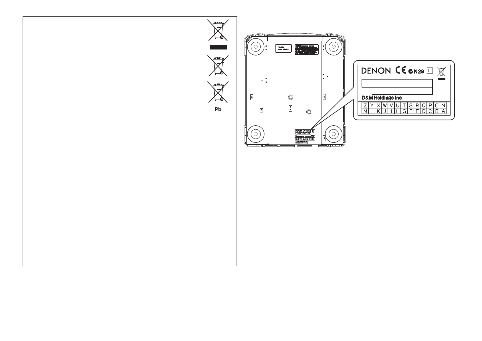
n Rating label
LOCATION: BOTTOM
MODEL NO. / MODELE NO. DN - SC2900
230V~ 5 0 Hz 30W
NO.
MADE IN CHINA/FABRIQUE EN CHINE
8W5441027700P
V
Page 7

Getting started
Getting started
Contents
Getting started ·······································································1
Accessories ···················································································· 2
About this manual ········································································2
Main features ················································································· 3
Cautions on handling ···································································· 3
Discs ·······························································································4
Discs playable on this unit ···························································· 4
Holding discs ················································································4
Loading discs ················································································ 4
Cautions on loading discs ····························································· 4
Cautions on storing discs······························································4
Cleaning discs ··············································································· 4
Supported media and files ··························································· 4
Supported media ··········································································4
Playable files ················································································· 4
Part names and functions ·················································5
Top panel ·······················································································5
q Audio input/output part ····························································5
w TRAKTOR LE 2/PRO 2 ·····························································7
Display ···························································································· 9
q Audio input/output part ····························································9
w TRAKTOR LE 2/PRO 2 ···························································10
Front panel ··················································································· 11
Rear panel ···················································································· 11
Preparations ···········································································12
About the supplied software ·····················································12
Installing the ASIO driver (Windows only) ·································· 12
Starting up the ASIO driver ························································· 14
Installing TRAKTOR LE 2 ···························································· 15
Automatic driver installation ·······················································16
Installing music management software “engine” ······················ 16
Obtaining the “engine for iPad”
music management application ·················································· 16
Connection··············································································17
Cables used for connection ························································ 17
Basic connections ·······································································17
Network connecting ···································································18
MIDI control connections ···························································19
Connecting the power cord························································19
Playback ···················································································20
Turning the power on ································································· 20
Turning the power off ································································· 20
Preparation for playback ····························································20
Preparing for CD playback ··························································20
Preparing for CD-ROM/CD-R/CD-RW playback ··························21
Preparing for USB memory device or HDD playback ·················22
Preparing for playback from a network connected device ··········23
Searching tracks ·········································································· 24
Searching tracks by category ······················································ 24
Searching tracks by crate ····························································25
Searching tracks by playlist ·························································25
Operations during playback ······················································· 26
Setting playback mode ·······························································26
Playback ······················································································ 26
Pause ·························································································· 26
Fast forward/Rewind ··································································26
Setting the cue point ··································································27
Adjusting the playback speed ····················································· 28
Adjusting the playback speed without changing the pitch ·········28
Changing the playback speed temporarily
(pitch bend function) ··································································· 28
Power on playback······································································28
Manual loop playback ·································································29
Auto loop playback······································································30
Hot cue playback ········································································30
Hot list ························································································31
Auto BPM counter ······································································ 31
Scratch playback ········································································· 31
Adjusting the rotation torque of the jog wheel ··························· 32
Adjusting the touch sensor sensitivity of the Jog wheel
(Touch Adjust) ············································································· 32
Reverse playback ········································································ 32
SLIP function ··············································································32
Adjusting the track startup/end time ··········································33
Network playback operations ···················································· 33
Sharing tracks on the network ···················································· 33
Relay playback ············································································ 34
Automatically adjusting BPM ······················································ 34
Sharing hot list information ························································· 35
Sharing memo data·····································································35
MIDI control operation······················································35
Basic operations ·········································································· 35
Switching between MIDI layers 1/2 ·········································· 35
Switching MIDI channels ···························································· 35
MIDI command list ······································································ 36
Send command···········································································36
Reception commands ································································· 37
Others························································································40
Memo function ············································································ 40
Media that can be used with the memo function ·······················40
Memo settings ···········································································41
Preset recall function ·································································· 42
How to make detailed settings ····································43
Utility menu map ········································································43
Utility settings ············································································· 44
Save As Def. ··············································································· 44
Preset Setting ············································································· 44
Preset I/O····················································································46
Memo Area ················································································· 46
Initialize ······················································································· 46
Information ·················································································46
Troubleshooting···································································47
Specifications ········································································48
Index ··························································································49
Part names and functions Preparations Connection MIDI Control
Playback
Others Settings
Troubleshooting Specifications Index
1
Page 8
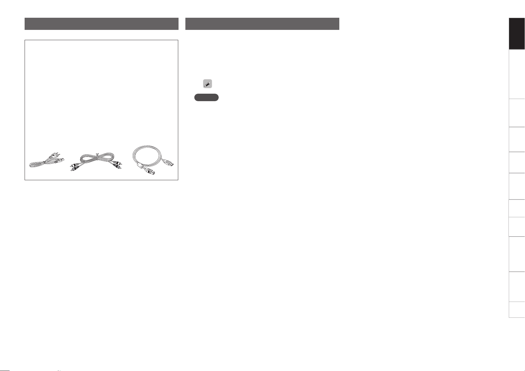
Accessories
Check that the following parts are supplied with the product.
q Owner’s Manual ...................................................................... 1
w Quick setup guide ................................................................... 1
e DN-SC2900 Resource disc ...................................................... 1
(Contents)
•Owner’s manual (This manual)
•Quick setup guide
•“engine” Instruction manual
•Music management software “engine”
•ASIO driver
•AUDIO/MIDI setup guide for MAC OS X
r DJ software (TRAKTOR LE 2) disc .......................................... 1
t Power cord (For use with this unit only) ................................. 1
y RCA cable ................................................................................ 1
u USB cable ................................................................................ 1
y ut
About this manual
n Symbols
v
m
NOTE
n Illustrations
Note that the illustrations in these instructions are for explanation
purposes and may differ from the actual unit.
This symbol indicates a reference page on
which related information is described.
This symbol indicates items described in the
“engine Instruction manual” on the provided
disc.
This symbol indicates a supplementary
information and tips for operations.
This symbol indicates points to remember
operations or function limitations.
Getting started
Part names and functions Preparations Connection MIDI Control
Playback
Others Settings
Troubleshooting Specifications Index
2
Page 9

Main features
1. Supplied with “engine”, new music management software
presented by DENON DJ (vmengine Instruction manual)
•Creates a database, and enables high-speed multifunctional
searching and efficient music file list management.
•Equipped with an automatic generation function that generates
BPM, beat points and waveform information, and editing function
for editing cue and loop points.
•Equipped with the PC-Link function that enables playback of tracks
managed by “engine” on a computer and searching of tracks
stored on a USB memory device or HDD connected to this unit
using “engine”.
2. Network Media Player equipped with advanced functions
•Tracks can be shared when two or more DN-SC2900 are connected
on the same network. (Maximum four DN-SC2900)
•By connecting an iPad to this unit using Wi-Fi and using the
“engine for iPad” music management application, you can use
the iPad touch screen to search tracks and display the status
(vpage16).
•CD, USB memory device or HDD tracks can be played, even when
using MIDI DJ software. This enables continued performance
without audio cutout even when restarting the computer or
changing DJs.
3. Built-in USB MIDI Control Function
•Equipped with a physical controller function that enables control of
the DJ software from this unit as well as the computer.
4. Supports CD-DA playback, CD-ROM (AAC, AIFF, MP3, WAV)
playback, and audio playback from USB memory device and
external HDDs (mass-storage class)
5. Built-in USB audio interface
•High sound quality design that supports sampling frequency of
44.1 kHz.
•Supplied with ASIO driver for low latency (vpage12).
6. Equipped with a large, high-resolution jog wheel with a
touch sensor function
7. Equipped with FL display and waveform display function
•Highly informative display provides three lines of character
information.
•Track waveform dataz is displayed.
•The 32-position marker point indicator follows your hand
movements quickly and accurately.
z To display waveform data, use the provided “engine” music
management software (vmengine Instruction manual).
8. Equipped with Burr Brown 24 bit DAC processing for faithful
playback and superior audio fidelity.
Cautions on handling
•Before turning the power switch on
Check once again that all connections are correct and that there are
no problems with the connection cables.
•Power is supplied to some of the circuitry even when the unit is
set to the standby mode. When going on vacation or leaving home
for long periods of time, be sure to unplug the power cord from the
power outlet.
•Proper ventilation
•If the unit is left in a room full of the smoke from cigarettes, etc.,
for long periods of time, the surface of the optical pickup may get
dirty, preventing it from receiving the signals properly.
•Place in a stable, flat location.
•About condensation
If there is a major difference in temperature between the inside of
the unit and the surroundings, condensation (dew) may form on
the operating parts inside the unit, causing the unit not to operate
properly.
If this happens, let the unit sit for an hour or two with the power
turned off and wait until there is little difference in temperature
before using the unit.
•Cautions on using mobile phones
Using a mobile phone near this unit may result in noise. If that
occurs, move the mobile phone away from this unit when it is in use.
•Moving the unit
•Turn off the power and unplug the power cord from the power
outlet. Next, disconnect the connection cables to other system
units before moving the unit.
•When carrying this unit with a platter installed, make sure that the
platter does not fall.
•When transporting this unit, remove the jog wheel and platter, and
package them separately for transportation.
•About care
•Wipe the cabinet and control panel clean with a soft cloth.
•Follow the instructions when using a chemical cleaner.
•Benzene, paint thinner or other organic solvents as well as
insecticide may cause material changes and discoloration if brought
into contact with the unit, and should therefore not be used.
Getting started
Part names and functions Preparations Connection MIDI Control
Playback
Others Settings
Troubleshooting Specifications Index
3
Page 10

Discs
Discs playable on this unit
q Music CDs
Discs marked with the logo at right can be
played in this unit.
w CD-R/CD-RW
NOTE
•Discs in special shapes
(heartshaped discs, octagonal
discs, etc.) cannot be played. Do
not attempt to play them, as
doing so can damage the unit.
•Some discs and some recording formats cannot be played.
•Non-finalized discs cannot be played.
z What is finalization?
Finalization is the process that makes recorded CD-R/CD-RW discs
playable on compatible players.
Holding discs
Cautions on loading discs
•Do not get fingerprints, oil or dirt on discs.
•Take special care not to scratch discs when removing them from
their cases.
•Do not bend or heat discs.
•Do not enlarge the hole in the center.
•Do not write on the labeled (printed) surface with ball-point pens,
pencils, etc., or stick new labels on discs.
•Water droplets may form on discs if they are moved suddenly from
a cold place (outdoors for example) to a warm place, but do not try to
dry them off using a hair-dryer, etc.
Cautions on storing discs
•Be sure to remove discs after using them.
•Be sure to store discs in their cases to protect them from dust,
scratches, warping, etc.
•Do not store discs in the following places:
•Places exposed to direct sunlight for long periods of time
•Dusty or humid places
•Places exposed to heat from heaters, etc.
Supported media and files
The following media and files can be played back on this unit.
Supported media
Disc
Disc type : CD, CD-R, CD-RW, CD-ROM
Format : CD-DA (CD-TEXT compatible),
CD-ROM (ISO9660/Joliet format)
USB memory device
Media type : FLASH, HDD
Format : FAT16/FAT32, HFS+ (Read only)
NOTE
•When a multisession disc is used, the more sessions there are, the
more time will be required to read the disc.
•When HFS+ is used, this unit may not be able to recognize the file
name if characters other than ISO8859-1 registered characters or
character codes other than Japanese are used.
Playable files
Getting started
Part names and functions Preparations Connection MIDI Control
Playback
Do not touch the signal surface.
Loading discs
•Only load one disc at a time. Loading two or more discs can damage
the unit or scratch the discs.
•When the disc is drawn into the unit, be careful not to trap your
fingers.
•Do not insert anything other than discs into the disc loading slot.
•Do not use cracked or warped discs or discs that have been repaired
with adhesive, etc.
•Do not use discs on which the sticky part of cellophane tape or labels
is exposed or on which there are traces of where labels have been
removed. Such discs can get caught inside the player and damage it.
•If the label side of the disc is dirty, wipe it clean before use. If the
disc loading/ejection roller becomes dirty, discs may not load or eject
correctly.
Cleaning discs
•If there are fingerprints or dirt on a disc, wipe them off before using
the disc. Fingerprints and dirt can impair sound quality and cause
interruptions in playback.
•Use a commercially available disc cleaning set or a soft cloth to clean
discs.
Gently wipe the disc from the
inside towards the outside.
NOTE
Do not use record spray, antistatic agents, benzene, thinner or other
solvents.
Do not wipe in a circular
motion.
4
File formats Extension Details
MP3 .mp3 CBR/VBR 44.1kHz Stereo
AAC
WAV .wav 44.1kHz 16/24bit Stereo
AIFF
.m4a
.aac
.aif
.aiff
CBR/VBR 44.1kHz Stereo
44.1kHz 16/24bit Stereo
NOTE
DRM protected files cannot be played back.
Others Settings
Troubleshooting Specifications Index
Page 11

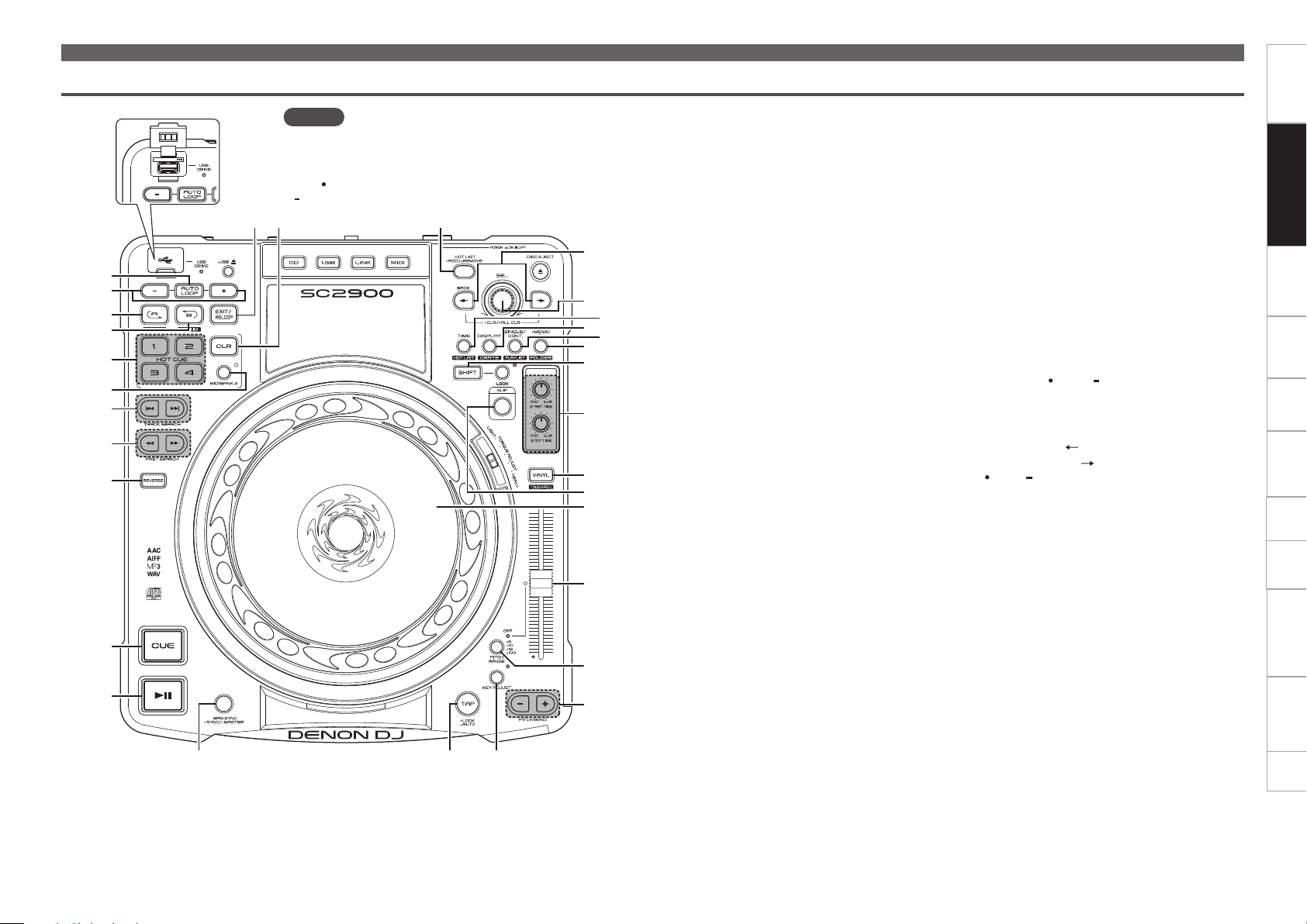
Part names and functions
Top panel
q Audio input/output part
This section describes the top panel in the following sections: q Audio input/output part and w TRAKTOR LE 2/PRO 2. Read descriptions for your DJ software.
For buttons not explained here, see the page indicated in parentheses ( ).
q Play/Pause button (13) ····························(26)
w CUE button ················································· (27)
e REVERSE button ········································ (32)
r FAST SEARCH buttons
(6, 7) ···················································· (26)
t TRACK SEARCH buttons (8, 9)
•8 : When this button is pressed, playback
is paused at the start of the previous track.
•9 : When this button is pressed, playback
is paused at the start of the next track.
y MIDI BANK 2 button ··································· (35)
u HOT CUE buttons (1/2/3/4) ······················· (30)
i B button (B TRIM) ······································· (29)
o A button (A TRIM) ······································ (29)
Q0 AUTO LOOP +/– buttons ··························· (30)
Q1 AUTO LOOP button ···································· (30)
Q2 USB port
Insert a USB memory device or connect a HDD.
Q3 USB DRIVE indicator ·································· (22)
Q4 USB eject button ( USB 5) ····················· (23)
Q5 EXIT/RELOOP button ································· (29)
Q6 Clear button (CLR) ······································ (30)
Q7 Source select buttons
(CD/USB/LINK/MIDI)
······················································· (20 – 23, 35)
Q8 Display ··························································· (9)
Q9 Hot List Add/Remove button
(HOT LIST ADD/ REMOVE) ················ (31)
Q1
Q0
o
i
u
y
t
r
e
5V 500mA
Q2
Q2
NOTE
Note that there are many buttons that have two different
functions that are selected by pushing the buttons for a short
time or long time (1 second or more).
The “ ” mark indicates a short time push function, and the
“ ” mark indicates a long time push function.
Q7Q3 Q4 Q5 Q6 Q8 Q9
W0
W1
W2
W3
W4
W5
W6
W7
W8
W9
E0
E1
E2
E3
E4
W0 BACK button ( ) ······················ (21, 24, 25, 44)
Forward button ( ) ··································· (24)
CLR/ ALL CLR button
······························································· (25, 30)
•BACK : Returns to the previous layer or
previous setting of the selected mode.
• : Switches the active panel within
“engine”. When the remaining track time is
below the set time, left and right selector knob
indicators flash alternately.
W1 DISC EJECT button (DISC EJECT5) ·········· (21)
W2 Selector knob (SEL.)
•Turn this knob to select modes or setting
values.
•Press this knob to choose the selected item.
•When searching for tracks on a music CD, turn
this knob while pressing it to select tracks in
10-track units.
•When searching for tracks from the database,
turn this knob while pressing it to jump to the
items that start with the specified first letter.
W3 TIME button ·················································· (9)
HOT LIST button ········································· (31)
W4 DISPLAY/CRATE button
•DISPLAY : When this button is pressed, the
display switches between the performance
screen and search screen, and the tag
information of the currently playing song is
displayed.
•CRATE : When this button is pressed while
W7 SHIFT is held down, the “engine” crate is
displayed.
Part names and functionsGetting started
Preparations Connection MIDI Control
Playback
Others Settings
Troubleshooting Specifications Index
w
q
E5
E6
E8R1 E7E9R0
5
Page 12

Top panel
Q1
Q0
o
i
u
y
t
r
e
w
q
5V 500mA
Q2
Q2
NOTE
Note that there are many buttons that have two different
functions that are selected by pushing the buttons for a short
time or long time (1 second or more).
The “
“ ” mark indicates a long time push function.
” mark indicates a short time push function, and the
Q7Q3 Q4 Q5 Q6 Q8 Q9
W0
W1
W2
W3
W4
W5
W6
W7
W8
W9
E0
E1
E2
E3
E4
E5
E6
E8R1 E7E9R0
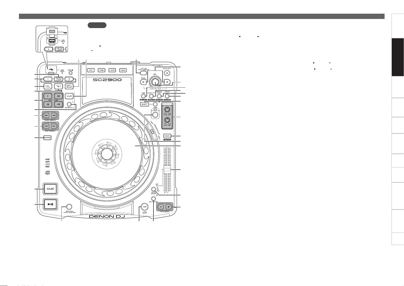
W5 SINGLE/CONT. button ······························· (26)
PLAYLIST button
•PLAYLIST : When this button is pressed while
W7 SHIFT is held down, the “engine” playlist
is displayed.
W6 Memo/Utility button
( MEMO/ UTIL.) ······························· (41, 44)
FOLDER button
•FOLDER : When this button is pressed while
W7 SHIFT is held down, the folders in the
USB memory device, HDD or “engine” are
displayed.
W7 SHIFT button
When i B TRIM, o A TRIM, W3 HOT LIST,
W4 CRATE, W5 PLAYLIST, W6 FOLDER or E1
TOUCH ADJ.
this button, the mode switches to the assigned
button mode.
are pressed while holding down
W8 Shift lock button (LOCK)
When this button is pressed, the shift function
locks, and the shift function can be used without
pressing W7 SHIFT. Press the button again to
release the lock.
W9 START TIME knob,
STOP TIME knob ········································ (33)
E0 TORQUE ADJUST switch
(LIGHT/HEAVY) ·········································· (32)
The rotation torque of the jog wheel can be
adjusted to one of 5 levels by sliding this switch.
Slide toward the “LIGHT” direction to reduce
rotation torque and the “HEAVY” direction to
increase rotation torque.
E1 VINYL button, Touch adjust button
(TOUCH ADJ.) ··························· (27, 28, 31, 32)
E2 SLIP button ················································· (32)
E3 Jog wheel ···················································· (27)
E4 Pitch slider ·················································· (28)
E5 PITCH RANGE button ································· (28)
E6 PITCH BEND button (+/–) ··························· (28)
E7 KEY ADJUST button ·································· (28)
E8 TAP LOCK/ AUTO button ···················· (31)
E9 Touch sensor indicator
Lights red when the unit detects that the top of
the jog wheel has been touched.
R0 Jog wheel indicator ····························· (27, 45)
The playback point lights red, and the cue point
lights purple.
However, you can change the color settings. For
details, see “Utility” – “Preset Setting” – “Jog
Ind. Color”.
R1 BPM SYNC/ MASTER button
····································································· (34)
Part names and functionsGetting started
Preparations Connection MIDI Control
Playback
Others Settings
Troubleshooting Specifications Index
6
Page 13
w TRAKTOR LE 2/PRO 2
Top panel
Q1
Q0
o
i
u
y
t
r
e
w
q
5V 500mA
NOTE
Note that there are many buttons that have two different
functions that are selected by pushing the buttons for a short
time or long time (1 second or more).
The “ ” mark indicates a short time push function, and the
“ ” mark indicates a long time push function.
Q3 Q4
Q2
E0E1 W9
Q5
Q6
Q8
W0
W1
W2
W3
W4
W5
W6
W7
W8
Q7
Q9
q Play/Pause button (13)
Plays back when pressed while playback is
stopped. Pauses playback when pressed during
playback.
w CUE button
Sets the cue point and stutters the cue point
when pushed repeatedly.
•Hold down W1 SHIFT and press this button to
jump to the start of the deck.
e REVERSE button
Shift modifier for sample slots.
r FAST SEARCH buttons (6, 7)
Fast forward/rewind.
t TRACK SEARCH buttons (8, 9)
Loads the file selected using Q6 SEL. to either
DECK A or DECK B.
y MIDI BANK 2 button
The button switches CUE1–4/SAMPLE SLOT1–
4.
•When SAMPLE SLOT1–4 is selected, the
display lights up.
u HOT CUE buttons (1/2/3/4)
y MIDI BANK 2 turn ON/OFF to select CUE1–
4/SAMPLE SLOT1–4. (This function is enabled
when the upgraded version TRAKTOR PRO 2
(sold separately) is used.)
ON:
•Press this button to playback the sample.
•Hold down W1 SHIFT and press this button to
playback the sample slot trigger.
•Hold down Q3 CLR and press this button to
switch mute for the sample slot ON or OFF.
•Press and hold W1 SHIFT and Q3 CLR together
and press this button to clear the sample slot.
•Hold down e REVERSE and press this button
to load the file selected in the browser to the
sample slot.
OFF: Up to 4 cue points can be set.
i B button (B TRIM)
Sets the loop out point.
o A button (A TRIM)
Sets the loop in point.
Q0 AUTO LOOP +/– buttons
Adjust the loop size.
•Hold down W1 SHIFT and press this button to
move the loop position left or right.
Q1 AUTO LOOP button
Switches auto loop ON/OFF.
Q2 EXIT/RELOOP button
Shift modifier for loading track deck to sample
slots.
Q3 CLR button
Q4 Hot List Add/Remove button
(HOT LIST ADD/ REMOVE)
Expands or Shrinks the browser window.
•Hold down W1 SHIFT and press this button to
appends title to preparation.
Q5 BACK button ( )
Forward button ( )
CLR/ ALL CLR button
Switch the displayed FAVORITES windows.
Q6 Selector knob (SEL.)
Turn the knob to scroll through the browser list,
and press the knob to select a file.
Turn the track selection knob:
Scrolls through the browser list.
•Hold down W1 SHIFT and turn to scroll through
the browser tree.
Press the track selection knob:
•Hold down W1 SHIFT and press this button
to open or close the directories/folders in the
browser tree.
Q7 TIME/HOT LIST button
Shift modifier for sample slot 1.
Q8 DISPLAY/CRATE button
Shift modifier for sample slot 2.
Part names and functionsGetting started
Preparations Connection MIDI Control
Playback
Others Settings
Troubleshooting Specifications Index
7
Page 14
Top panel
Q1
Q0
o
i
u
y
t
r
e
w
q
5V 500mA
NOTE
Note that there are many buttons that have two different
functions that are selected by pushing the buttons for a short
time or long time (1 second or more).
The “
“ ” mark indicates a long time push function.
Q3 Q4
Q2
” mark indicates a short time push function, and the
Q5
Q6
Q8
W0
W1
W2
W3
W4
W5
W6
W7
W8
Q7
Q9
Q9 SINGLE/CONT. /PLAYLIST button
Shift modifier for sample slot 3.
W0 Memo/Utility ( MEMO/ UTIL.)/
FOLDER button
Shift modifier for sample slot 4.
W1 SHIFT button
W2 START TIME knob:
Adjust the cut off frequency of the sample slot.
STOP TIME knob:
Adjust the volume of the sample slot.
W3 VINYL button
ON: Switches to VINYL mode.
•The touch sensor is enabled when in VINYL
mode.
OFF: Switches to BEND mode.
•The touch sensor is disabled when in BEND
mode.
W4 SLIP button
Switches the sample slot filter ON/OFF.
•Hold down Q7 TIME and press this button to
switch the sample slot 1 filter ON/OFF.
•Hold down Q8 DISPLAY and press this button
to switch the sample slot 2 filter ON/OFF.
•Hold down Q9 SINGLE/CONT. and press this
button to switch the sample slot 3 filter ON/
OFF.
•Hold down W0 MEMO-UTIL. and press this
button to switch the sample slot4 filter ON/
OFF.
W5 Jog wheel
Performs the search operation or bend operation.
•Hold down W1 SHIFT and turn to scroll through
the list.
W6 Pitch slider
Adjusts the playback pitch.
•Move the knob toward the “–” direction to
slow down the pitch and the “+” direction to
speed up the pitch.
W7 PITCH RANGE button
Switches pitch range.
W8 PITCH BEND button (+/–)
Adjust the pitch temporarily.
W9 KEY ADJUST button
With this ON, the key does not change even if
you adjust the tempo during playback.
E0 TAP LOCK/ AUTO button
E1 BPM SYNC/ MASTER button
Performs auto beat matching.
•Hold W1 SHIFT and press this button to set
the currently selected deck to the beat sync
master deck.
Part names and functionsGetting started
Preparations Connection MIDI Control
Playback
Others Settings
Troubleshooting Specifications Index
E0E1 W9
8
Page 15

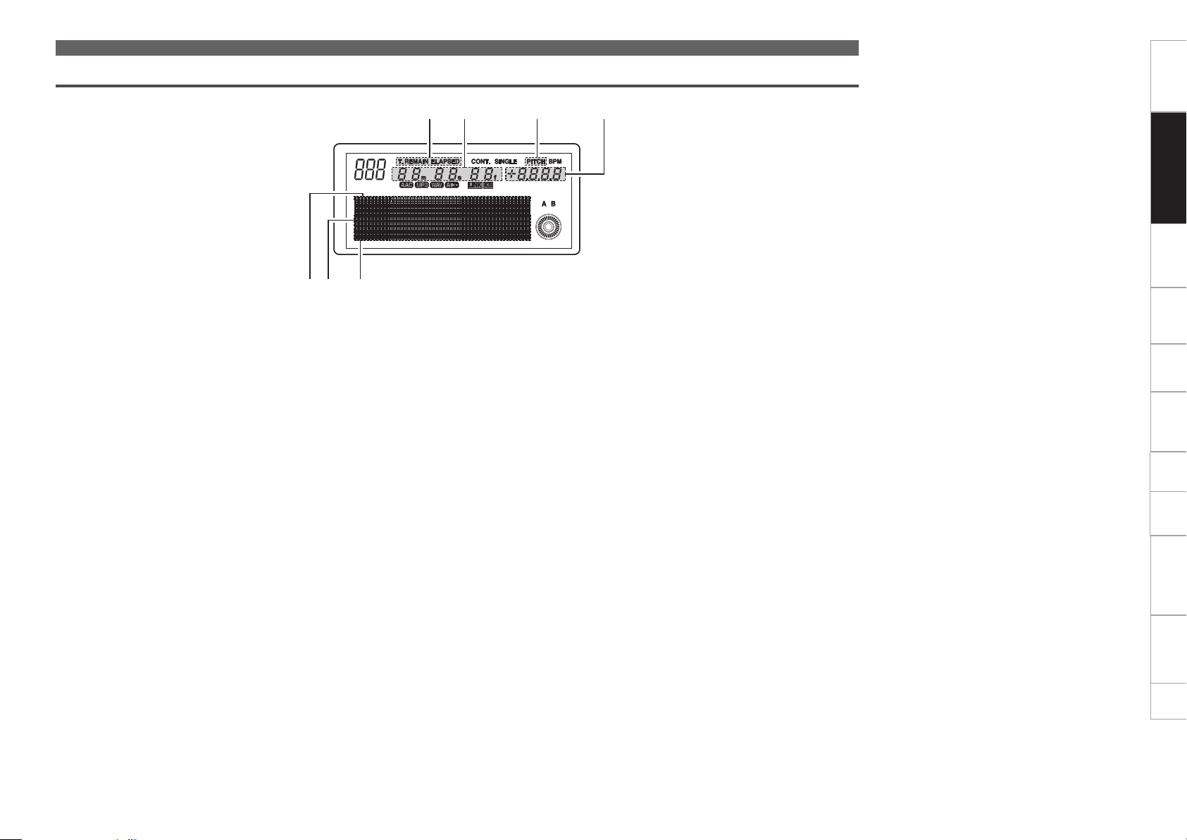
Display
q Audio input/output part
This section describes the display in the following sections: q Audio input/output part and w TRAKTOR LE 2/PRO 2. Read descriptions for your DJ software.
Part names and functionsGetting started
qw e r t y ui Q0o
q Play position indicator
The track playback time is displayed.
The normal playback time is displayed in blue,
and the reverse playback time is highlighted.
When the remaining playback time is below the
set time, the playback position indicator flashes.
w Point indicators
Indicates the where the cue point, hot cue or
auto loop point is in the playback position.
e Character and Waveform display section
Displays characters in the lower section of the
waveform display.
In the character display, information such as the
operation, mode name and data is displayed.
The item name selected in the setting operation
is highlighted.
r File data indicators
Format of the file being played back is displayed.
t LINK Connection confirmation indicator
Lights when a track on the device connected to
LINK is being played back.
Q2Q3Q4Q5Q6Q7
Waveforms are not displayed when there is no
waveform data.
Q1
y KEY ADJ. indicator
Lights when key adjustment mode is used.
u MEMO indicator
This indicates whether or not there is memo
data.
•Lights when memo data is stored in the file or
track that is playing back or in standby.
•When connected by LINK in CD mode, this
lights when memo data is stored in the USB
memory device of the connected device.
i Scratch marker
Playback position is displayed.
o Loop mode indicators
This unit has two types of loop mode indicators,
A and B.
The respective A and B indicators are displayed
when A or B are set.
The two arrows indicate the loop mode as
shown below.
•When both of flash:
Manual loop playback
•When the right side of flashes:
Manual loop paused (during exit)
Q0 WFM indicator
This lights when waveform data exists in the
track being played back or CD track.
Q1 PITCH display
This indicator displays the playback speed
(pitch).
Q2 PITCH mode indicator
This indicates the pitch in the PITCH display.
Q3 Play mode indicators
•CONT. : Lights when in continuous playback
mode.
•SINGLE : Lights when in single playback mode
or single playback (play lock) mode.
Q4 Minute, second and frame displays
This displays times such as the elapsed time or
remaining time for files or tracks.
Q5 Time mode indicators
Each time TIME is pressed, the indicator
switches as shown below.
•ELAPSED : Elapsed time of the track or file is
displayed.
•REMAIN : Remaining time of the track or file
is displayed.
•T.ELAPSED : When in CD mode, the elapsed
time from the first file of the CD is displayed.
•T.REMAIN : When in CD mode, the remaining
time of all tracks in the CD is displayed.
Q6 Track indicator
When in playlist mode playback or CD mode
playback, the number of the track currently
being played is displayed.
When in the USB mode or LINK mode, “Network
ID” is displayed.
Q7 SOURCE displays
The source currently being played back is
displayed.
Preparations Connection MIDI Control
Playback
Others Settings
Troubleshooting Specifications Index
9
Page 16
w TRAKTOR LE 2/PRO 2
Display
q Play position indicator
The track playback time is displayed.
The normal playback time is displayed in blue,
and the reverse playback time is highlighted.
When the remaining playback time is below the
set time, the playback position indicator flashes.
w Track name (Scrolled)
e Artist name (Scrolled)
qw e
r PITCH display
This indicator displays the playback speed
(pitch).
t PITCH mode indicator
This indicates the pitch in the PITCH display.
y Minute, second and frame displays
This displays times such as the elapsed time or
remaining time for files or tracks.
tyu
r
Part names and functionsGetting started
Preparations Connection MIDI Control
u Time mode indicators
Each time TIME is pressed, the indicator
switches as shown below.
•ELAPSED : Elapsed time of the track or file is
displayed.
•REMAIN : Remaining time of the track or file
is displayed.
•T.ELAPSED : When in CD mode, the elapsed
time from the first file of the CD is displayed.
•T.REMAIN : When in CD mode, the remaining
time of all tracks in the CD is displayed.
Playback
Others Settings
10
Troubleshooting Specifications Index
Page 17

Front panel
For buttons not explained here, see the page indicated in parentheses ( ).
Rear panel
For buttons not explained here, see the page indicated in parentheses ( ).
Part names and functionsGetting started
Preparations Connection MIDI Control
q Disc loading slot ········································· (20)
Insert discs here. Insert the disc slowly with the
label side facing upwards. Release the disc as
soon as you feel the unit pull in the disc.
q
q Power switch
(POWER ON/OFF) ······································· (20)
w AC inlet (AC IN) ···········································(19)
e AC cord holder ············································ (19)
This holder prevents the AC cord plug from
being pulled out. Use a screwdriver to fix the AC
cord to the holder.
r Network terminal (LINK) ····················· (17, 18)
Terminal for connecting to other devices via the
network. Connect this unit and the computer
to the same network in order to use “engine”.
A maximum of 4 DN-SC2900 units can be
connected via the network to 1 computer.
t FADER jack ············································ (17, 18)
Terminal for connecting to a DJ mixer, and
receiving various control signals (playback,
pause, cue etc) for controlling this device from
the mixer.
ewq
y
iutr
y USB B port (USB B (PC/MIDI)) ·················· (19)
Terminal for USB connections. Use to connect
this device to a computer for controlling DJ
software.
u Digital output terminal
(DIGITAL OUT) ···································· (17 – 19)
Outputs digital audio signals.
i Analog output terminals
(LINE OUT) ·········································· (17 – 19)
Outputs analog audio signals.
They are unbalanced RCA output terminals.
Playback
Others Settings
Troubleshooting Specifications Index
11
Page 18

Preparations
About the supplied software
Before connecting this unit to a computer, install the software on the supplied CD-ROM onto the computer.
•ASIO Driver
•Music management software “engine”
n About this unit and computer
•Computers running the following computer OS versions can be connected to this unit.
•Mac OS X 10.6 or later
•Windows XP SP3 or later (32 bit only)
•Windows Vista SP2 or later (32 or 64 bit)
•Windows 7 SP1 or lator (32 or 64 bit)
Computers running other OS versions may not be compatible with the USB MIDI. For this reason, the
computer may not operate correctly after connecting this unit to the computer via USB.
z Mac, Mac OS, iPad, iTunes and Quicktime is a registered trademark or trademark of Apple Inc. in the
United States and/or other countries.
z Windows is a registered trademark or trademark of Microsoft Corporation in the United States and/or
other countries.
n Software Upgrade
Please be sure to update with the latest firmware. From time to time, we will make improvements to
current features or add new features.
We will try to include ideas from customers’ feedback where possible. The updates are made available
via our www.denondj.com website.
Installing the ASIO driver (Windows only)
•Use the following steps to install the ASIO driver.
•When using a Mac, no installation is required.
Insert the supplied “DN-SC2900
1
Resource disc” into the computer.
The browse screen for the disc drive is
displayed.
•If the browse screen is not displayed, click the
disc drive on My Computer.
Click “Asio Driver Installation”.
The ASIO Driver Setup Wizard is launched.
2
Click “Next >”.
The license agreement screen (License
3
Agreement) appears.
DENON DJ ASIO Driver
Welcome to the DENON DJ ASIO Driver Setup
Wizard
The installer will guide you through the steps required to install DENON DJ ASIO Driver on your
computer.
WARNING: This computer program is protected by copyright law and international treaties.
Unauthorized duplication or distribution of this program, or any portion of it, may result in severe civil
or criminal penalties,and will be prosecuted to the maximum extent possible under the law.
DENON DJ ASIO Driver
License Agreement
< Back
Getting started Part names and functions Connection MIDI Control
Preparations
Playback
Next >Cancel
Others Settings
12
Please take a moment to read the license agreement now. if you accept the terms below, click “l
Agree”, then “Next”, Otherwise click “Cancel”.
I Do Not Agree
SOFTWARE LICENSE AGREEMENT
I Agree
< Back
Next >Cancel
NOTICE TO USER: Please read this Agreement carefully. By installing and
using all or any portion of the software (“Software”) supplied by D&M Holdings
Inc (“D&M”), you accept all the terms and conditions of this Agreement. You
agree that this agreement is enforceable like any written negotiated agreement
signed by you. This Agreement is enforceable against you and person or
legal entity that obtained the software and on whose behalf it is used. If you do not
agree, do not install or use this Software.
Troubleshooting Specifications Index
Page 19

About the supplied software
Please take a moment to read the license agreement now. if you accept the terms below, click “l
Agree”, then “Next”, Otherwise click “Cancel”.
License Agreement
DENON DJ ASIO Driver
SOFTWARE LICENSE AGREEMENT
The installer will install DENON DJ ASIO Driver to the following folder.
Select Installation Folder
DENON DJ ASIO Driver
Create lcons
DENON DJ ASIO Driver
The installer is ready to install DENON DJ ASIO Driver on your computer.
Click “Next” to start the installation.
Confirm Installation
DENON DJ ASIO Driver
Getting started Part names and functions Connection MIDI Control
If you agree, select “I Agree” and
4
click “Next >”.
A screen for selecting the folder in which
the ASIO driver is to be installed appears
(Select Installation Folder).
NOTICE TO USER: Please read this Agreement carefully. By installing and
using all or any portion of the software (“Software”) supplied by D&M Holdings
Inc (“D&M”), you accept all the terms and conditions of this Agreement. You
agree that this agreement is enforceable like any written negotiated agreement
signed by you. This Agreement is enforceable against you and person or
legal entity that obtained the software and on whose behalf it is used. If you do not
agree, do not install or use this Software.
I Do Not Agree
DENON DJ ASIO Driver
Select Installation Folder
The installer will install DENON DJ ASIO Driver to the following folder.
To install in this folder, click “Next”. To install to a different folder, enter it below or click “Browse”.
Folder:
C:¥Program Files¥DENON_DJ¥DDJASIO¥
Install DENON DJ ASIO Driver for yourself. or for anyone who uses this computer:
Everyone
Just me
NOTE
If “I Do Not Agree” is selected, “Next >” cannot
be clicked.
I Agree
< Back
< Back
Next >Cancel
Browse...
Disk Cost...
Next >Cancel
Click “Next >”.
A screen for verifying whether or not to
5
create a desktop shortcut appears (Create
Icons).
To install in this folder, click “Next”. To install to a different folder, enter it below or click “Browse”.
Folder:
C:¥Program Files¥DENON_DJ¥DDJASIO¥
Install DENON DJ ASIO Driver for yourself. or for anyone who uses this computer:
Everyone
Just me
DENON DJ ASIO Driver
Create lcons
Tell setup if you want it to create to a few icons for convenient access to the DENON DJ ASIO
Driver
Create icon on Desktop
•The default installation folder for the ASIO driver
is “C:/Program Files/DENON_DJ/DDJASIO”.
To change this location, click “Browse” and
select a different folder.
•Select “Everyone” to share use of this software
on the computer, or select “Just me” to use
yourself without sharing.
< Back
Browse...
Disk Cost...
Next >Cancel
Next >< BackCancel
To create an icon, check “P” into the
6
checkbox, and click “Next >”.
The installation start screen (Confirm
Installation) is displayed.
Tell setup if you want it to create to a few icons for convenient access to the DENON DJ ASIO
Driver
Create icon on Desktop
Next >< BackCancel
DENON DJ ASIO Driver
Confirm Installation
The installer is ready to install DENON DJ ASIO Driver on your computer.
Click “Next” to start the installation.
Next >< BackCancel
Click “Next >”.
Installation begins.
7
Next >< BackCancel
When the following installation
8
completion screen (Installation
Complete) is displayed, click
“Close”.
DENON DJ ASIO Driver
Installation Complete
DENON DJ ASIO Driver has been successfully installed.
Click “Close” to exit.
Close< BackCancel
n Uninstalling the ASIO driver
The software can be uninstalled from the control
panel on the computer.
Preparations
Playback
Others Settings
Troubleshooting Specifications Index
13
DENON DJ ASIO Driver
Installing DENON DJ ASIO Driver
DENON DJ ASIO Driver is being installed.
Please wait...
< Back
Cancel Next >
Page 20

Starting up the ASIO driver
Start the ASIO driver from the DJ software or desktop icon.
“ASIO Control Panel” appears on the computer display.
n Control panel screen (ASIO Control Panel)
u y
DENON DJ ASIO Driver Ver.2.2.2
Devices
SC2900_1
Disable
Device Description
Device Name:
Unit Number.
Software Version:
Audio input channels:
Audio output channels:
Sampling frequency:
Bit resolution:
Audio buffer size:
Audio Buffer Size
512sample(11ms)
SC2900_1
1
0.057
0
2
44.1 kHz
16 / 24 bit
512
OK
Sampling Rate
44.1kHz
48.0kHz
88.2kHz
96.0kHz
Bit Resolution
16 bit
24 bit
Cancel
rew tq
q Device list (Devices)
All connected DENON DJ devices are displayed
in a list.
(Example: SC2900_1)
•When the device that you want to check is
selected from the list, the current settings of
the selected device are displayed in u.
NOTE
Select one device at a time. Multiple devices
cannot be selected at the same time.
w ASIO Device switching button
(Enable/Disable)
This button is used for switching a device
selected in q (Devices) to enable or disable as
an ASIO device.
GASIO device statusH
Enable : The device name is displayed in bold,
and a check mark appears on the left.
Disable : The device name is displayed in light
face, and the check mark on the left side is
removed.
The ASIO device status can also be switched by
double clicking the device name.
The ASIO device status switches as shown
below each time the device name is double
clicked q.
Enable Disable
e Audio Buffer Size
Use this slider to adjust the buffer size.
If sound skipping occurs during playback,
increase the numerical value. However, if delay
occurs, reduce the numerical value.
About the supplied software
r OK/Cancel buttons
OK : Enters the setting changes.
Cancel : Cancels the setting changes.
t Bit Resolution
Displays the selection status of the bit resolution.
y Sampling Rate
The sampling rate selection is displayed here.
The DENON DJ ASIO driver supports 44.1 kHz,
48 kHz, 88.2 kHz and 96 kHz frequencies. 44.1
kHz is selected when this unit is connected.
u Device Description
This is the area in which information for the
device selected in the device information list is
displayed.
The following are displayed:
•Device Name
•Unit Number
•Software Version
•Audio input channels
•Audio output channels
•Sampling frequency
•Max bit resolution
•Audio buffer size
NOTE
If the device’s information cannot be acquired,
“–” (hyphens) are displayed for all items.
Getting started Part names and functions Connection MIDI Control
Preparations
Playback
Others Settings
Troubleshooting Specifications Index
•The adjustable range is 88 – 2048 samples. It
can be adjusted in 1 ms units.
•When you set multiple devices to enable as
ASIO devices, the same setting values apply
to all ASIO devices.
14
Page 21

Installing TRAKTOR LE 2
About the supplied software
Getting started Part names and functions Connection MIDI Control
Use the following steps to install the DJ software “TRAKTOR LE 2” in the supplied disc.
n Installation onto a Mac computer
Insert disc “TRAKTOR LE 2” into your computer.
The TRAKTOR LE 2 disc icon is displayed on the desktop.
1
Double-click the TRAKTOR LE 2 disc icon.
Files contained in the TRAKTOR LE 2 disc are displayed for
2
browsing.
Double-click “Traktor Installer” .
A window opens and the TRAKTOR LE 2 installation starts.
3
•Select Complete installation or Custom installation to start
installation. If you are unsure about the Custom installation, select
the Complete installation option.
Follow each step in the installation screen for
4
installation.
When the installation completes, close the
5
installation screen.
•After the installation, activate the software. For information about
how to activate the software, see Service Center Manual, which
is located in the Documentation folder under the Service Center
folder that is created during the installation.
•It is recommended that you use the latest version of the TRAKTOR
LE 2 software.
•For information about how to use the DJ software, see the
instruction manual for the DJ software or the help menu.
•The serial number is printed on the back of the disc case.
•TRAKTOR LE 2 is an NI software. To install and use the software,
you have to accept the software license agreement.
D&M shall not be responsible for any problems with your computer
and other software that may arise from the installation and use of
TRAKTOR LE 2.
n Installation onto a Windows computer
Insert disc “TRAKTOR LE 2” into your computer.
The browse screen for the disc drive is displayed.
1
•If the browse screen is not displayed, click the disc drive on My
Computer.
Double-click “Traktor Setup.exe” .
2
A window opens and the TRAKTOR LE 2 installation starts.
•Select Complete installation or Custom installation to start
installation. If you are unsure about the Custom installation, select
the Complete installation option.
Follow each step in the installation screen for
3
installation.
When the installation completes, close the
4
installation screen.
•If the ASIO Control Panel is open, close it before starting TRAKTOR
LE 2.
•After the installation, activate the software. For information about
how to activate the software, see Service Center Manual, which
is located in the Documentation folder under the Service Center
folder that is created during the installation.
•It is recommended that you use the latest version of the TRAKTOR
LE 2 software.
•For information about how to use the DJ software, see the
instruction manual for the DJ software or the help menu.
•The serial number is printed on the back of the disc case.
•TRAKTOR LE 2 is an NI software. To install and use the software,
you have to accept the software license agreement.
D&M shall not be responsible for any problems with your computer
and other software that may arise from the installation and use of
TRAKTOR LE 2.
NOTE
•When using multiple DENON DJ devices such as DN-SC2900,
change “Unit No.” (vpage 44) in the Utility settings so that
there are no duplicate numbers.
•When using DN-SC2900 with a DENON DJ mixer (DN-X1700/
DN-X1600/DN-X600), set the sampling frequency (FS) on the
DENON DJ mixer (DN-X1700/DN-X1600/DN-X600) to 44.1 kHz. For
how to set this, see the owner’s manual of the DENON DJ mixer
(DN-X1700/DN-X1600/DN-X600).
•It has been verified that this unit works properly with the TRAKTOR
LE 2/PRO 2 software.
•Use the latest version of the TRAKTOR mapping file (tsi file). The
latest version can be downloaded at www.denondj.com.
Preparations
Playback
Others Settings
Troubleshooting Specifications Index
15
Page 22

About the supplied software
Getting started Part names and functions Connection MIDI Control
Automatic driver installation
When this unit is connected to the computer, drivers for the unit are automatically installed on the computer.
When this device is connected to a Windows computer, the following message is displayed at the bottom
right of the screen.
Found New Hardware
USB AUDIO Device
When the installation is completed, the following message is displayed at the bottom right of the screen.
Found New Hardware
Your new hardware is installed and ready to use.
If your computer’s OS is Windows, on the DN-SC2900 select “Utility” – “Preset Setting” – “PC/
MAC” (vpage45) – “PC”. The factory setting is “MAC”.
Installing music management software “engine”
Install the “engine” software in the supplied disc onto your computer. For details on the installation
method and operations, see the mengine Instruction manual.
Obtaining the “engine for iPad” music management application
You can download “engine for iPad” from the App Store (within the iTunes Store).
Preparations
Playback
Others Settings
16
Troubleshooting Specifications Index
Page 23

Connection
Getting started Part names and functions Preparations MIDI Control
Cables used for connection
Select the cables according to the equipment being connected.
n For LINE OUT terminals
L
R
RCA cable (supplied)
n For DIGITAL OUT terminals
Coaxial cable (sold separately)
n For FADER jack
Stereo mini cable (sold separately)
n For LINK terminal
Ethernet cable (sold separately)
n For USB B (MIDI) port
USB cable (supplied)
L
R
Basic connections
•This is an example of the basic connections when connecting this unit to a DJ mixer.
or
R
L
USB memory
device or HDD
5V 500mA
R
L
L
R
IN
Connection
FADERDIGITAL-
Playback
Others Settings
NOTE
•Do not plug in the power cord until all connections have been
completed.
•When making connections, also refer to the operating instructions of
the other components.
•Be sure to connect the left and right channels properly (left with left,
right with right).
•Connect the cables to the correct input and output terminals.
•Insert the plugs securely. Loose connections will result in the
generation of noise.
•Do not bundle power cords together with connection cables. Doing
so can result in humming or noise.
DN-SC2900
DN-SC2900DJ mixer
NOTE
•USB hubs cannot be used.
•In order to prevent playback output clipping due to differences in playback level when an effector is used, set the playback level to –6 dB from
the normal playback level after converting digital output to analog.
•DENON does not guarantee that all USB memory devices will operate or receive power. When using a portable USB connection type HDD of
the kind to which an AC adapter can be connected to supply power, use the AC adapter.
17
Troubleshooting Specifications Index
Page 24

Network connecting
•This is an example of connecting multiple DN-SC2900 units to a computer via a network and router. A maximum of four DN-SC2900 units can be connected.
•Use the following type of network cable.
•RJ45 category 5 (CAT5) or higher.
•STP or ScTP cable.
•Either cross cables or straight cables can be used.
R
or
USB memory
device or HDD
R
L
L
L
R
FADERDIGITAL-
IN
Router
Getting started Part names and functions Preparations MIDI Control
Computer
Connection
Playback
5V 500mA
DN-SC2900
DN-SC2900 DN-SC2900 DN-SC2900DJ mixer
•Install the “engine” music management software on the computer that will be connected to this unit.
•In order for “engine” to recognize multiple connected units, use “Utility” – “Preset Setting” – “Network ID” (vpage44) to set the different network ID for each unit.
•We recommend you use a router that has a DHCP server function for network connections. When a switching hub is used, it may take a few minutes to determine the network address after connection.
NOTE
•Always connect DN-SC2900 to a computer using a wired LAN.
•After the router is started, connect the router to DN-SC2900 and your computer and power them on.
•If the computer has multiple LAN ports, we recommend disabling all LAN ports other than the one being used. If the other ports are not disabled, the link with this unit may not be established.
•Do not connect the router to the internet or WAN. Doing so may cause playback sound to cut out, or devices may not be able to connect correctly.
•This unit can be connected directly to a computer without using a router. In this case, set the computer’s network address settings to a fixed IP address, and use the following settings:
IP address: 169.254.0.1 Subnet Mask: 255.255.0.0
•When connecting 4 units to a computer, use a router or LAN hub that has 5 or more LAN ports.
•When connecting using a router, this unit and the computer should be connected to LAN ports.
18
Others Settings
Troubleshooting Specifications Index
Page 25

MIDI control connections
•This is an example of connecting this unit to a computer with DJ MIDI software installed, and operating this unit using MIDI control operations.
•Be sure to use the supplied USB cable for connection.
•If your computer OS is Windows, select “Utility” – “Preset Setting” – “PC/MAC” (vpage45) – “PC”.
If your computer OS is Mac, select “Utility” – “Preset Setting” – “PC/MAC” (vpage45) – “MAC”.
The default setting is “MAC”.
Computer
R
or
R
L
L
L
R
DIGITAL-
IN
Connecting the power cord
Connect the supplied power cord to this unit, and insert the plug into
the wall socket.
NOTE
•Do not plug in the power cord until all connections have been
completed.
•Insert the plug fully and securely into the socket. Incomplete
connection to the power supply may cause damage to the unit, or
noise.
AC cord holder
Getting started Part names and functions Preparations MIDI Control
Connection
Playback
DN-SC2900
DJ mixer
NOTE
DJ MIDI Software is not supplied with this unit.
When using a MIDI control connection, install separate DJ software on the computer. For details on the installation method, see the instruction
manual included with the DJ software.
19
Power cord
(supplied)
To AC outlet
(AC 230 V, 50 Hz)
To prevent the power plug from falling out, we recommend fixing the
power cord to the AC cord holder. Use a Phillips screwdriver to fix the
power cord to the AC cord holder.
Others Settings
Troubleshooting Specifications Index
Page 26

Playback
CD
DISC 5BACKSHIFT SEL.
Getting started Part names and functions Preparations Connection MIDI Control Troubleshooting Specifications Index
CUE
Turning the power on
Press POWER ON/OFF.
“DENON DJ” appears on the display, and the power switches on.
Turning the power off
Press POWER ON/OFF.
The power switches off.
NOTE
Do not switch off the power while inserting or ejecting a disc. Doing
so may damage the operating part of the CD, and may cause the unit
to malfunction.
Preparation for playback
This section explains how to operate each type of media.
Preparing for CD playback
Press CD to switch the source to CD.
1
Insert a CD into the disc loading slot.
The first track on the CD is cued in standby mode, and CUE
2
lights.
Turn SEL. to select the track you want to play.
Playback
3
•Press and turn SEL. to select 10 tracks at a time.
Press SEL.
4
The cue standby mode is set at the start of the selected tracks.
Others Settings
POWER ON/OFF
20
Page 27

Preparing for CD-ROM/CD-R/CD-RW
playback
•Prepare to play tracks from a CD-ROM/CD-R/CD-RW.
•For details on the files that can be played on this unit, see page 4.
NOTE
This section explains the operating procedures for CD-ROM/CD-R/
CD-RW discs that have been finalized as data CDs. For CDs that
have been finalized as music CDs, see “Preparing for CD playback”
(vpage20).
Press CD to switch the source to CD.
1
Insert a CD into the disc loading slot.
•The folder names and track names on the disc are shown in
2
the display.
•Files are in the selected state.
Turn SEL. to select the folder that contains the track
3
you want to play.
Press SEL.
4
The folder names or track names within the folder are shown
in the display.
Preparation for playback
n Ejecting CDs
Press DISC 5.
The CD is ejected from the disc loading slot.
NOTE
Be sure the CD is paused before ejecting. If DISC 5 is pressed during
CD playback, the CD will not be ejected.
n If the CD cannot be ejected
If the CD is not ejected due to a malfunction in the unit even when
DISC 5 is pressed, it can be ejected using other buttons.
Hold down SHIFT, and press CD.
The CD is ejected from the disc loading slot.
Getting started Part names and functions Preparations Connection MIDI Control Troubleshooting Specifications Index
Playback
Turn SEL. to select the track you want to play.
5
•Press BACK to return to the previous folder.
Press SEL.
6
The cue standby mode is set at the start of the selected tracks.
21
Others Settings
See the illustration on the previous page for details of the buttons used for the
operations on this page.
Page 28
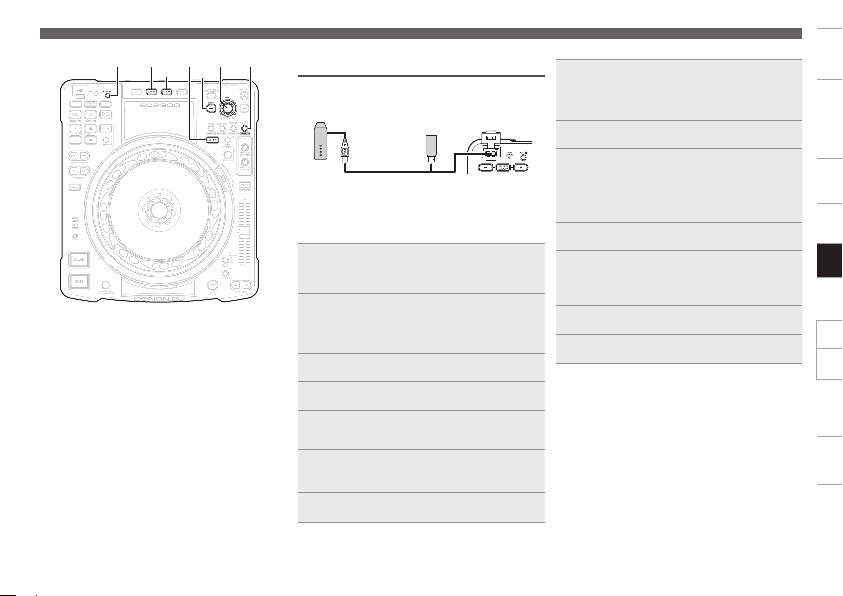
USB
SHIFT
USB 5
LINK
SEL. FOLDER
BACK
Preparing for USB memory device or HDD
playback
•Connect USB memory device or HDD to the USB port on the top
panel, and prepare to playback a track.
•For details on the file formats that can be played on this unit, see
page 4.
USB memory
device or HDD
5V 500mA
n Using a database
Creating a music search database using the “engine” music
management software enables high-speed multifunctional music
searching.
This section explains how to use a database to prepare for playback.
Create a music search database.
1
•Use the “engine” music management software to create a music
search database (vmengine Instruction manual).
Connect a USB memory device or HDD to the USB
2
port.
The USB DRIVE indicator flashes red, and then remains lit.
When the indicator is lit, the USB memory device or HDD can
be used.
Press USB to switch the source to USB.
3
Preparation for playback
n When not using a database
Connect a USB memory device or HDD to the USB
1
port.
The USB DRIVE indicator flashes red, and then remains lit.
When the indicator is lit, the USB memory device or HDD can
be used.
Press USB to switch the source to USB.
2
Hold down SHIFT, and press FOLDER.
3
The mode switches to folder search mode, and the folder
names or track names within the root folder are shown in the
display.
•If a database does not exist on the USB memory device or HDD,
the mode automatically switches to folder search mode.
Turn SEL. to select the folder.
4
Press SEL.
5
The folder names or track names within the selected folder are
shown in the display.
•Press
BACK to go back 1 folder level.
Turn SEL. to select the track you want to play.
6
Press SEL.
7
The cue standby mode is set at the start of the selected tracks.
Getting started Part names and functions Preparations Connection MIDI Control Troubleshooting Specifications Index
Playback
Others Settings
Turn SEL. to select “TITLE”.
4
Press SEL.
5
Titles of the tracks that are registered to the database are
shown in the display.
Turn SEL. to select the track you want to play.
6
•You can also search for tracks by category (vpage24).
Press SEL.
7
The cue standby mode is set at the start of the selected tracks.
22
Page 29

•FAT16/FAT32 and HFS+ (read only) formats are supported for the
USB memory device and HDD.
•When using a USB HDD of the kind to which an AC adapter can be
connected to supply power, use the AC adapter.
•If the USB memory device is not recognized, disconnect the USB
memory device and then reconnect it.
NOTE
•Depending on the type of mass-storage USB memory device
or portable music player, it may take some time for this unit to
recognize the device.
•Do not connect devices or cables that do not conform to USB
standards.
•USB memory devices will not work via a USB hub.
•When HFS+ is used, this unit may not be able to recognize the file
name if characters other than ISO8859-1 registered characters or
character codes other than Japanese are used.
•HDDs up to 2 TB in size can be formatted using this unit. Larger
HDDs are not supported.
•NTFS format USB memory devices and HDDs are not supported. If
used, this unit may malfunction.
•When using a HDD that has an automatic power ON/OFF function
that switches the HDD power on and off in sync with the computer,
disable this function in the settings.
n Removing the USB memory device or HDD
Press and hold USB 5.
1
When the USB DRIVE indicator turns off, disconnect
2
the USB memory device or HDD from the USB port.
NOTE
•Be sure the USB memory device or HDD is paused before removing.
•When removing USB memory device or HDD, use the above
procedure to turn off the USB DRIVE indicator before removing.
Incorrectly removing the USB memory device or HDD may damage
the data stored on the device.
•DENON cannot accept any responsibility whatsoever for the damage
or loss of data from USB memory devices or HDDs that are used in
conjunction with this device.
•There is no guarantee that this unit is compatible with all types of
USB memory devices or HDDs.
Preparing for playback from a network
connected device
•When this unit is connected via a network, tracks can be shared
between multiple DN-SC2900 units, and tracks stored on the
computer can also be shared. This section explains how to prepare
for playback of tracks from devices connected via the network.
•For details on the file formats that can be played on this unit, see
page 4.
n Sharing tracks between multiple DN-SC2900
units
Connect 2 or more DN-SC2900 units to the network
1
(vpage 18).
•A maximum of four DN-SC2900 units can be connected to the
network.
•Before starting, use “Utility” – “Preset Setting” – “Network ID”
(vpage44) to set the different network ID for each unit.
Press LINK.
2
The “Network ID” list of all units connected to USB memory
devices and HDDs are shown in the display.
Select the “Network ID” of the unit connected to the
3
USB memory device or HDD that contains the track
you want to play back.
Turn SEL. to select “TITLE”.
4
Press SEL.
5
Titles of the tracks that are registered to the database are
shown in the display.
Turn SEL. to select the track you want to play.
6
•You can also search for tracks by category (vpage24).
Press SEL.
7
The cue standby mode is set at the start of the selected tracks.
Preparation for playback
n Sharing tracks between this unit and a
computer
When this unit is connected to a computer, check that the following
application is installed on the computer.
•Music management software “engine” (vpage16)
Connect this unit to the computer (vpage 18).
1
•Only one computer can be connected to this unit.
Start “engine” on the computer.
An icon representing the unit connected to the network is
2
shown in the “engine” screen.
Press LINK.
3
The “Network ID” list of all units connected to USB memory
devices and “engine” is shown in the display.
Select “engine” from the “Network ID” list.
4
Turn SEL. to select the track you want to play.
5
Press SEL.
6
The cue standby mode is set at the start of the selected tracks.
•For details of how to operate “engine”, see mengine Instruction
manual.
Getting started Part names and functions Preparations Connection MIDI Control Troubleshooting Specifications Index
Playback
Others Settings
23
See the illustration on the previous page for details of the buttons used for the
operations on this page.
Page 30

Searching tracks
USB BACK PLAYLIST
SHIFT
This section explains how to search for tracks using a database
created using music management software “engine”.
CRATE
SEL.
Searching tracks by category
Tracks can be searched from the following categories.
•TITLE
•GENRE
•BPM
•ARTIST
•ALBUM
n Searching tracks from 1 category
GExampleH Searching for tracks by artist name
Press USB to switch the source to USB.
1
The search top menu is shown in the display.
•To display the search top menu from the playback screen, press
BACK
.
Turn SEL. to select “ARTIST”.
2
Press SEL.
3
Artist names that are registered to the database are shown as
a list in the display.
Turn SEL. to select the artist name from the list.
4
Press SEL.
5
A list of tracks by the selected artist is shown in the display.
Turn SEL. to select the track you want to play from
6
the list.
Press SEL.
7
•The title of the selected track is shown in the display.
•The cue standby mode is set at the start of the selected
tracks.
n Searching tracks by multiple categories
GExampleH Searching for tracks by genre and album name
Press USB to switch the source to USB.
1
The search top menu is shown in the display.
Turn SEL. to select “GENRE”.
2
Press SEL.
3
Genres that are registered to the database are shown as a list
in the display.
Turn SEL. to select the genre from the list.
4
Press →.
Enter the search conditions, and the search top menu is shown
5
in the display.
Turn SEL. to select “ALBUM”.
6
Press SEL.
7
Album names that are registered to the database are shown as
a list in the display.
Turn SEL. to select the album name from the list.
8
Press SEL.
9
A list of track names that are refined by the categories selected
in the display (genre, album name) is shown.
Turn SEL. to select the track you want to play from
10
the list.
Press SEL.
11
•The title of the selected track is shown in the display.
•The cue standby mode is set at the start of the selected
tracks.
Getting started Part names and functions Preparations Connection MIDI Control Troubleshooting Specifications Index
Playback
Others Settings
24
Page 31

Cancelling search conditions
Searching tracks by crate
Searching tracks by playlist
Searching tracks
Getting started Part names and functions Preparations Connection MIDI Control Troubleshooting Specifications Index
Press BACK.
1
The search top menu is shown in the display.
Turn SEL. to select the category that you want to
2
cancel from the categories set as search conditions.
Press SEL.
3
Artist names that are registered to the database are shown as
a list in the display.
Turn SEL. to select “ALL”.
4
Press SEL.
5
Cancels the search conditions.
Cancelling all search conditions
Hold down BACK, and press →.
All of the set category search conditions are cancelled.
Use the crate created by “engine” to search tracks.
Hold down SHIFT, and press CRATE.
1
The crate list is shown in the display.
Turn SEL. to select a crate.
2
Press SEL.
3
A list of sub-crates within the selected crate is shown in the
display.
•Press
BACK to go back 1 crate level.
Press →.
•Tracks within the selected crate are searched.
4
•The search top menu is shown in the display.
Turn SEL. to select the track you want to play from
5
the list.
Press SEL.
6
•The title of the selected track is shown in the display.
•The cue standby mode is set at the start of the selected
tracks.
Use the playlist created by “engine” to search tracks.
Hold down SHIFT, and press PLAYLIST.
1
The playlist list is shown in the display.
Turn SEL. to select the playlist you want to search.
2
Press SEL.
3
The titles of the tracks within the selected playlist are shown
in the display.
Turn SEL. to select the track you want to play from
4
the list.
Press SEL.
5
•The title of the selected track is shown in the display.
•The cue standby mode is set at the start of the selected
tracks.
Playback
Others Settings
25
See the illustration on the previous page for details of the buttons used for the
operations on this page.
Page 32

Operations during playback
6 7
VINYL SINGLE/
Getting started Part names and functions Preparations Connection MIDI Control Troubleshooting Specifications Index
CUE 13
Jog wheel
CONT.
Setting playback mode
This sets how tracks are played back.
Press SINGLE/CONT.
•The playback mode is switched in the following order each time
the button is pressed.
SINGLE (PLAY LOCK) SINGLE
CONT.
SINGLE
(PLAY LOCK)
SINGLE
CONT.
NOTE
“CONT.” mode cannot be used when this unit is linked to “engine”.
The mode is forcibly changed to “SINGLE” mode.
The SINGLE indicator lights in the display, and “Play
Lock” is shown. In this mode, when playback of the
track is completed, the track returns to the cue point
and is paused.
The SINGLE indicator lights in the display, and “Lock
Off” is shown. In this mode, when playback of the
track is completed, the track returns to the cue point
and is paused.
The CONT. indicator in the display lights. In this mode,
when playback of the track has finished, the next track
is played back.
Playback
Press 13.
13 lights green, and playback starts.
Pause
Press 13 during playback.
13 flashes, and the track is paused.
•Press 13 again to resume playback from the point at which the
track was paused.
•The track that is playing is paused when the jog wheel is touched
while VINYL is lit.
Fast forward/Rewind
There are two methods for fast forward/rewinding.
n Fast forward/Rewind using 6 7 buttons
Fast forward/Rewind during playback
Press 6 7 during playback.
The playback point is moved approximately 3 seconds from the
current point, and playback is resumed from the new playback point.
Press and hold 6 7 during playback.
The playback point moves at high speed, and playback starts at the
point where the button is released.
Fast forward/Rewind during pause
Press 6 7 when the track is paused.
The playback point moves 1 frame at a time, and pause is resumed
at the new point.
Press and hold 6 7 while the track is paused.
The playback point moves at high speed, and pause is resumed at
the new point.
Playback
Others Settings
26
Page 33

n Using the jog wheel for fast forward/rewind
Press VINYL.
1
VINYL mode switches off, and VINYL goes out.
Press 13 during playback.
2
13 flashes, and the track is paused.
Turn the jog wheel to nd the playback point.
The playback point moves 1 frame at a time.
3
Press 13.
4
Playback resumes from the next playback point.
Setting the cue point
By setting a cue point, the track can be played back from the set
position.
n Setting the cue point mode
The operating procedures for setting the cue point differs
depending on the mode. Select the desired operating procedure
along with the mode.
Switch the cue point setting mode in “UTILITY” –
“Preset Setting” – “Cue Mode” (vpage 45).
Standard
DENON
•The default setting is “Standard”.
Sets the cue point by the standard method used in
general DJ products.
Sets the cue point in the same way as conventional
DENON DJ products.
n Setting the cue point
n When using “Standard” mode
Pause the track in the position where you want to set
the cue point, and press CUE.
The cue point is set at the paused position.
n When using “DENON” mode
Pause the track in the position where you want to set
the cue point, and start playback.
The cue point is set at the paused position.
•Irrespective of the mode, the cue point is set at the start of the
track when the track is loaded.
The cue point lights purple on the jog wheel indicator.
However, you can change the color settings. For details, see “Utility”
– “Preset Setting” – “Jog Ind. Color” (vpage45).
n Returning to the cue point
•Playback stops, returns to the position where you want to playback
again (cue point), and is paused (back cue function).
•When this function is used, playback can always be started from
the same position.
During playback, press CUE.
Playback stops, cues to the playback start position (cue point), and
pauses.
Operations during playback
n Moving the cue point
There are two methods for moving the cue point, using 6 7
buttons, or using the jog wheel.
Setting with 6 7 buttons
When playback is paused, press 6 7 and move
1
the cue point to the position where you want to set it.
The cue point moves 1 frame each time the button is pressed.
n When using “Standard” mode
2
Press CUE.
The cue point is set at the moved position.
n When using “DENON” mode
Press 13.
The cue point is set at the moved position, and playback
starts.
Setting with the jog wheel
Press VINYL.
1
VINYL lights blue.
Turn the jog wheel while playback is paused to move
2
the cue point to the position where you want to set it.
•You can search for the cue point by listening to the playback sound
in 1 frame units.
n When using “Standard” mode
3
Press CUE.
The cue point is set at the moved position.
Getting started Part names and functions Preparations Connection MIDI Control Troubleshooting Specifications Index
Playback
Others Settings
27
n When using “DENON” mode
Press 13.
The cue point is set at the moved position, and playback
starts.
See the illustration on the previous page for details of the buttons used for the
operations on this page.
Page 34

VINYLA, B
SHIFTEXIT/
RELOOP
Adjusting the playback speed
Use the pitch slider to adjust the playback speed (pitch).
n Using the jog wheel
When VINYL mode is off
Operations during playback
Getting started Part names and functions Preparations Connection MIDI Control Troubleshooting Specifications Index
Jog wheel
Press PITCH RANGE.
1
The PITCH RANGE indicator lights on the display.
Each time the button is pressed, the range in which the playback
speed can be adjusted switches as shown below.
6 % 10 % 16 %
100%OFF
Move the pitch slider, and adjust to the desired
2
playback speed.
Press VINYL, and VINYL illumination goes out.
1
The mode switches to BEND/SCRATCH mode.
Turn the jog wheel during playback.
Turn the jog wheel to the right to increase the pitch, and left to
2
decrease the pitch.
When VINYL mode is on
Press VINYL, and VINYL illumination lights blue.
1
Adjusting the playback speed without
changing the pitch
When the playback speed is adjusted, the pitch is not changed.
Press KEY ADJUST.
The KEY ADJ. indicator lights on the display.
PITCH BEND +/–PITCH RANGE
KEY ADJUST
Pitch slider
Changing the playback speed temporarily
(pitch bend function)
This function temporarily changes the playback speed.
There are 2 methods for changing the playback speed.
n Using the PITCH BEND buttons
Press PITCH BEND +/–.
PITCH BEND +
PITCH BEND –
Playback speed is increased while the button is
being pressed.
Playback speed is decreased while the button is
being pressed.
Turn the jog wheel during playback.
The playback speed changes according to the rotation speed
2
of the jog wheel.
Power on playback
If the power is turned on when a disc is loaded in the disc loading slot,
playback starts from the first track on the disc.
Set “Utility” – “Preset Setting” – “Power on Play”
(vpage 45) to “ON”.
When using a finalized CD-ROM/CD-R/CD-RW as a data CD, only save
music files directly root of the disc.
Playback
Others Settings
28
Page 35

Manual loop playback
-30 f -1 f+30 f
z z
Set the starting point (A point) and end point (B point), and playback is
repeated seamlessly between the two points.
During playback or pause, press A at the position
1
where you want to start playback.
The A indicator lights in the display, and playback starts from
the set A point.
Press B at the position where you want to end
2
playback.
The B indicator lights in the display, and manual loop playback
repeats between A and B.
When using “DENON” (vpage27) mode
In normal playback or pause, press EXIT/RELOOP.
n If the current playback position is before the A-B
positions,
•“Exit Off” is shown in the display.
•When the playback position passes the A point (start point)
manual loop playback starts automatically.
n If the current playback position is after the A-B
positions,
•Moves the playback point to the A point (start point) and manual
loop playback starts.
Operations during playback
Adjusting the B point (end point)
During manual loop playback, press and hold SHIFT,
1
and press B.
Turn the jog wheel while listening to the playback
2
sound, and move to the position where you want to
end playback.
•It can be adjusted in 1 frame units.
GAdjustable rangeH
It can be adjusted from 1 frame after the A point (start point) to the
end of the track.
z
Getting started Part names and functions Preparations Connection MIDI Control Troubleshooting Specifications Index
When the file or track is changed, the set loop points are erased.
n Changing the end point of manual loop playback
During manual loop playback or pause, press B at the
position where you want to end playback.
•The B point (end point) is moved to the position where B was
pressed.
n Exiting manual loop playback
During manual loop playback, press EXIT/RELOOP.
“Exit Loop” is shown in the display, and normal playback resumes.
n Returning to manual loop playback
When using “Standard” (vpage27) mode
In normal playback, press EXIT/RELOOP.
The playback position moves to the A point (start point) and manual
loop playback starts.
If the EXIT/RELOOP button is pressed before the playback point
passes the A point (start point), “Exit Loop” is shown in the display,
and normal playback resumes.
n Adjusting loop points
Adjusting the A point (start point)
During manual loop playback, press and hold SHIFT,
1
and press A.
Turn the jog wheel while listening to the playback
2
sound, and move to the position where you want to
start playback.
•It can be adjusted in 1 frame units.
GAdjustable rangeH
•Range up to ±30 frames from A point (start point).
•Range up to 1 frame before the B point (end point).
A
z Adjustment range for A point
Press A at the position where you want to end
3
playback.
A point (start point) adjustment is complete.
B
A
+1 f
z Adjustment range for B point
Press B at the position where you want to end
3
playback.
B point (end point) adjustment is complete.
B
End of the track
Playback
Others Settings
29
See the illustration on the previous page for details of the buttons used for the
operations on this page.
Page 36

AUTO LOOP +/–
HOT CUE 1 ~ 4 TAPCLR SHIFTTIME
HOT LIST
VINYL
EXIT/
AUTO LOOP
RELOOP
SEL.
ADD/REMOVE
Auto loop playback
This function automatically repeats playback in time with the beat.
n Setting auto loop playback
Press AUTO LOOP.
•AUTO LOOP lights, and the A and B indicators in the display flash.
•The playback position when the button is pressed is set as the A
point (start point). From there, the beat source set in “Auto Loop
Cnt.” (vpage45) is automatically set as the B point (end point),
and auto loop playback starts between A – B.
NOTE
If the BPM of the track being played is not set, auto loop playback may
not operate correctly.
n Adjusting the auto loop playback range
Expanding the loop range
Press AUTO LOOP +.
•Each time the button is pressed, the loop range expands as shown
below.
X2 X4 X8 X16
•The B point (end point) moves to match the expanded loop range.
•The B point (end point) maximum range limit is the end of the track.
Reducing the A-B loop range
Operations during playback
n Exiting auto loop playback
During auto loop playback, press EXIT/RELOOP.
Auto loop playback exits, and normal playback resumes.
Hot cue playback
The positions (hot cue points) where you want to start playback can be
registered in HOT CUE 1 – 4.
n Registering hot cue points
At the position where you want to start playback, press
one of HOT CUE 1 – 4 that are lit dim blue.
The pressed button lights a bright blue, and the hot cue point is
registered.
NOTE
Buttons that are lit bright blue already have hot cue points registered,
and cannot be overwritten. Cancel the current hot cue point registration
in order to re-register a hot cue point.
n Hot cue playback
Press one of HOT CUE 1 – 4 that are lit bright blue.
Playback starts from the hot cue point set to the pressed button.
n Clearing hot cue points
Getting started Part names and functions Preparations Connection MIDI Control Troubleshooting Specifications Index
Playback
Others Settings
Press AUTO LOOP –.
•Each time the button is pressed, the loop range reduces as shown
below.
X1/2 X1/4 X1/8 X1/16
•The B point (end point) moves to match the reduced loop range.
•The minimum range for the B point (end point) is 1 frame after the
A point.
30
Press and hold CLR and press one of HOT CUE 1 – 4 whose
registration you want to cancel.
The hot cue point is cleared from the pressed button.
Page 37

Hot list
When the track list (search screen) is being displayed, a selected track
can be temporarily registered to the music file list (hot list).
NOTE
When the unit power is switched off, all of the contents registered to
the created hot list are cleared.
n Registering to the hot list
Turn SEL. to display the track you want to register.
1
Press HOT LIST ADD/REMOVE.
2
“Add” is displayed, and the selected track is registered to the
hot list.
n Playing tracks registered to the hot list
Hold down SHIFT, and press TIME.
1
The hot list is shown in the display.
Turn SEL. to select the track you want to play.
2
Press SEL.
3
The cue standby mode is set at the start of the selected tracks.
n Clearing tracks from the hot list
Hold down SHIFT, and press TIME.
1
The hot list is shown in the display.
Turn SEL. to select the track you want to clear.
2
Press and hold HOT LIST ADD/REMOVE.
3
The selected track is cleared.
n Sharing hot lists
When multiple DN-SC2900 units, are connected via a network, hot
lists can be shared between units.
For details, “Sharing hot list information” (vpage35).
Auto BPM counter
During playback or cue standby, the tempo (BPM) of the track is
automatically measured and displayed.
n Auto BPM counter
Press and hold TAP.
•The auto BPM counter switches on, and the tempo (BPM) is
shown in the display.
•If the track changes when the BPM is locked, the lock is removed,
and the auto BPM counter switches on.
NOTE
Depending on the track, the automatic BPM measurement may not
be performed correctly. In this case, perform “TAP Input” or “Manual
BPM input”, and measure manually.
Operations during playback
n BPM lock
This function locks data measured by the auto BPM counter.
When the auto BPM counter is on, press TAP.
“BPM LOCK” is shown in the display, and the data measured by the
auto BPM counter is locked.
n Measuring BPM manually
TAP Input
The tempo (BPM) is measured according to the interval between
repeated pressings of the TAP.
When BPM is locked, repeatedly press TAP in time with
the beat.
The measured tempo (BPM) is shown in the display.
Manual BPM Input
Enter the tempo (BPM) as a number.
Hold down TAP, and turn SEL.
1
BPM value appears on the display.
Turn SEL. to the tempo (BPM) you want to set, and
2
release TAP.
The set value is entered, and data is locked.
•Press and turn
SEL. to enter numbers below the decimal point.
Scratch playback
Turn the jog wheel during playback to use scratch playback.
Getting started Part names and functions Preparations Connection MIDI Control Troubleshooting Specifications Index
Playback
Others Settings
31
Press VINYL, and select “VINYL MODE”.
1
VINYL lights blue.
Turn the jog wheel.
Scratch playback starts.
2
•When the jog wheel is released, scratch playback ends and normal
playback resumes.
See the illustration on the previous page for details of the buttons used for the
operations on this page.
Page 38

Operations during playback
SEL.LINK SHIFTREVERSE
Getting started Part names and functions Preparations Connection MIDI Control Troubleshooting Specifications Index
Jog wheel
TIME
Adjusting the rotation torque of the jog
wheel
Adjusts the rotation torque of the jog wheel to the torque you want
to set.
Slide TORQUE ADJUST.
Slide toward the “LIGHT” direction to reduce rotation torque and the
“HEAVY” direction to increase rotation torque.
The rotation torque can be adjusted during playback.
Adjusting the touch sensor sensitivity of
Reverse playback
This function plays back the track in reverse.
During playback, press REVERSE.
Reverse playback starts from the playback point where the button
was pressed.
•Each time
normal and reverse playback.
•Reverse playback switches off when hot cue playback is used.
•When using reverse playback in SINGLE mode, when the playback
position reaches the start of the track, playback switches to cue
standby.
REVERSE is pressed, playback switches between
the Jog wheel (Touch Adjust)
Adjusts the sensitivity of the touch sensor when the top of the Jog
wheel is touched.
Hold down SHIFT, and press VINYL.
1
VINYL flashes.
Turn SEL. to select a touch sensor sensitivity.
2
•Touch sensor sensitivity is displayed in 5 levels. The factory
STOP
TIME
TORQUE
ADJUST
VINYLSLIPSTART
setting is “2”.
GAdjustable rangeH
Min, 1, 2, 3, Max
Press SEL.
3
Touch sensor sensitivity is set.
You can adjust touch sensor sensitivity even while playing a track.
n Exiting reverse playback
During reverse playback, press REVERSE.
Reverse playback exits, and normal playback resumes.
SLIP function
You can continue playback at the same beat even after reverse
playback, loop playback, or scratch playback.
During playback, press SLIP.
SLIP lights red, and the SLIP function is enabled.
•The playback point moves in the normal playback direction even
during reverse playback, loop playback, or scratch playback.
•After a playback operation ends, normal playback resumes from
the playback point reached.
Playback
Others Settings
32
n Disabling the SLIP function
When the SLIP function is enabled, press SLIP.
SLIP goes out, and the slip function is disabled.
Page 39

Operations during playback
Adjusting the track startup/end time
This function adjusts the track startup and end times. By using this
function, tracks can be started and stopped with similar characteristics
to an analog player.
n Adjusting the track startup time
Turn START TIME.
•Turn to the left to make the track startup time faster.
•Turn to the right to make the track startup time slower.
n Adjusting the track end time
Turn STOP TIME.
•Turn to the left to make the track end time faster.
•Turn to the right to make the track end time slower.
Network playback operations
This section explains the operations used when the unit is
connected to the network.
Sharing tracks on the network
Tracks on the USB memory device or computer are shared.
n Sharing between DN-SC2900 units
(Players Link)
•When more than one DN-SC2900 units are connected, tracks can
be shared between units.
•In this example, a USB memory device connected to a
DN-SC2900 unit set with “Network ID” “1” is searched by
another DN-SC2900 unit with the “Network ID” “2”, and tracks
are played back from the USB memory device.
•In “Utility” – “Preset Setting” – “Network ID” (vpage44),
set the Network IDs for the DN-SC2900 units in advance.
Press LINK on the unit set as “Network ID” “2”, and
1
select the unit whose “Network ID” is “1”.
•The search status of the unit set as “Network ID” “2”
becomes the same as the unit set as “Network ID” “1”.
•When the unit set as “Network ID” “2” is operated, the unit
set as “Network ID” “1” performs the same operations in
sync.
Search and enter the track on the unit set as
2
“Network ID” “2”.
The unit set as “Network ID” “2” switches to cue standby.
n Sharing between this unit and a computer
(PC Link)
•Tracks can be shared between this unit and a computer
•In this example, tracks on the computer are searched and played
using the unit set as “Network ID” “1”.
Press LINK on the unit set as “Network ID” “1”, and
1
select “engine”.
•The unit set as “Network ID” “1” is displayed on the
“engine” control panel.
•The unit set as “Network ID” “1” can be used as the
“engine” controller.
Turn SEL. to search for a track, and press SEL. on
2
the unit set as “Network ID” “1”.
The track is loaded, and the unit set as “Network ID” “1”
switches to cue standby.
•For details of how to operate “engine”, see mengine Instruction
manual.
NOTE
•If the same “Network ID” is used between different units, they
cannot be connected on the network. If the same network IDs are
duplicated, “SET ID >>>1 (duplicated “Network ID” number)” is
displayed. Use SEL. to set another “Network ID”.
•When sharing tracks between this unit and the computer, firewall
settings on the computer need to be cancelled for “engine”. For
details on the setting method, see mengine Instruction manual.
Getting started Part names and functions Preparations Connection MIDI Control Troubleshooting Specifications Index
Playback
Others Settings
33
See the illustration on the previous page for details of the buttons used for the
operations on this page.
Page 40

Network playback operations
SEL.
MIDI BANK 2 MIDI
Getting started Part names and functions Preparations Connection MIDI Control Troubleshooting Specifications Index
HOT CUE 1 ~ 4
13
BPM SYNC
Pitch slider
Relay playback
•When multiple DN-SC2900 units are connected on the network,
tracks are played back in the order of the registered “Network ID”
number. A maximum of four DN-SC2900 units can be connected.
•Before starting, use “Utility” – “Preset Setting” – “Network ID”
(vpage44) to set the Network IDs.
Set “Utility” – “Preset Setting” – “Relay” (vpage 45)
to “ON”.
The mode switches to relay playback.
•In relay playback, tracks are played in the following order.
•If relay playback mode is off for a unit, tracks are not played.
•If a “Network ID” number is missing, the number is skipped for
playback.
“Network ID” : 1 “Network ID” : 2
“Network ID” : 4 “Network ID” : 3
•When “OFF” is selected in “Utility” – “Preset Setting” – “Relay”
(vpage45), normal playback is resumed.
•If relay playback mode is set to ON during playback, relay playback
starts from the next track.
n About the track playback order
Depending on the playback mode, the track playback order differs.
For details, see “Setting playback mode” (vpage26).
In SINGLE playback mode
When playback of the track ends, playback of the next track starts on
the player registered with the next “Network ID”.
Automatically adjusting BPM
When multiple DN-SC2900 units, are connected on the network, the
BPM value from the desired player (MASTER) is set as the BPM on all
other players (Slave) (BPM SYNC function).
n Set as “Master”
This sets the device that will be the standard when adjusting the
BPM value.
Press and hold BPM SYNC on the device that you want
to be “MASTER”.
•“SYNC Master” appears on the display.
•BPM SYNC flashes, and the “Master” setting is complete.
•When the “Master” is set, all other connected players are set as
“Slave”.
•If another player is already set as “Master”, set the other players to
“Slave” before setting the desired unit to “Master”.
n Setting the “Master” BPM to the “Slave” BPM
Press BPM SYNC on the unit set as “Slave”.
•“BPM-SYNC” is shown in the display, and the BPM is set to the
“Master” BPM.
•The PITCH indicator flashes, and the pitch value is shown in the
display.
•Pitch adjustment is locked.
Playback
Others Settings
In CONTINUOUS playback mode
When playback of the last track ends, playback of the first track starts
on the player registered with the next “Network ID”.
34
•When the pitch value at which the pitch slider is locked is matched,
the pitch lock is released.
•Even if the connection between units in the BPM SYNC status is
cancelled, pitch lock is maintained.
•When the track on the “Master” unit changes, the “Master”
settings are transferred to the initially synced “Slave”. At this time, if
the pitch is locked for the “Master” device, pitch lock is maintained.
NOTE
This setting cannot be used unless one of the devices is set to
“Master”.
Page 41

Network playback operations
n Automatically setting the “Slave” beat grid to
the “Master” beat grid
•When the beat grid is cancelled using “engine” for the “Master”
track and “Slave” track, the playback position can be adjusted to
match the grid at the moment when the “Slave” matches the
“Master” (beat grid SYNC function).
•This function can be set in “Utility” – “Preset Setting” – “Beat
Point” (vpage45).
•For details of how to operate beat grid, see mengine Instruction
manual.
NOTE
Beat grid is only available for tracks registered in the database. It
cannot be used with CDs.
Sharing hot list information
•Hot lists can be shared between units that are connected via a
network.
•When multiple DN-SC2900s are connected on the network, hot lists
are displayed together as 1 list. At this time, the hot list is created in
the order of registration.
For details on hot lists, see page 31.
Sharing memo data
•Memo data saved on a USB memory device or HDD can be shared
between devices connected to the network.
•When multiple DN-SC2900 units are connected on the network,
memo data is created together as 1 list.
About the memo function see page 40.
MIDI control operation
This unit is equipped with a USB MIDI command input/output function.
Using this function, the DJ MIDI software on the computer can be controlled using this device.
•For details on how to operate the DJ MIDI software, see the DJ MIDI software instruction manual or help menu.
Basic operations
Connect this unit using the provided USB cable
1
to a computer that has DJ software installed
(vpage 19 “MIDI control connections”).
Press MIDI.
2
The MIDI indicator lights on the display.
Turn SEL. and then select the MIDI mode.
3
Changes to the MIDI mode in which the USB audio
OK
interface and the MIDI control are available.
Cancel
4
5
•Tracks played back by the DJ software can be output via this
device.
Cancels the MIDI mode selection operation and
switches to the original device.
Press SEL.
The MIDI indicator in the display lights, and the mode switches
to MIDI control mode.
Operate the buttons and knobs on this unit to output
MIDI commands.
The DJ software on the computer is controlled.
Switching between MIDI layers 1/2
The MIDI layer of the HOT CUE 1 – 4 buttons can be switched.
By switching the MIDI layer, the MIDI commands that can be output
change.
Press MIDI BANK 2.
•The MIDI layer is switched as shown below.
MIDI layer 1
(MIDI BANK 2 indicator
goes out)
(MIDI BANK 2 indicator
Switching MIDI channels
•You can connect more than one DN-SC2900 to a computer to control
DJ software. Switch MIDI channels as needed.
•Set a MIDI channel for each connected device.
The default setting is “1”.
Select a MIDI channel to set by selecting “Utility” –
“Preset Setting” – “MIDI CH” (vpage 45).
NOTE
Before using the MIDI control mode, install the DJ software in the
computer to which this unit is connected. After the installation, install
the mapping file for operating data on the computer with this unit.
Getting started Part names and functions Preparations Connection Troubleshooting Specifications Index
MIDI layer 2
lights)
Playback
MIDI Control
Others Settings
35
See the illustration on the previous page for details of the buttons used for the
operations on this page.
Page 42

MIDI command list
Getting started Part names and functions Preparations Connection
Send command
items
1 Disc EJECT
2 VINYL 4 E-1
3 Pitch Range 5 F-1
4 KEY ADJUST 6 F#-1
5 TAP 7 G-1
6 Pitch Bend + 8 G#-1
7 Pitch Bend – 9 A-1
8 Track Search + 12 C0
9 Track Search – 13 C#0
10 Fast search + 16 E0
11 Fast search – 17 F0
12 DISPLAY MODE 22 A#0
13 HOT1 23 B0
14 HOT2 24 C1
15 HOT3 25 C#1
16 CLR 26 D1
17 AUTO LOOP 29 F1
18 HOT4 32 G#1
19 TIME 35 B1
20 MEMO/Util 36 C2
21 CONT./SINGLE 38 D2
22 SELECT SW 40 E2
23 FWD 41 F2
24 BACK 48 C3
25 MIDI 51 D#3
26 USB 53 F3
27 A 55 G3
28 B 57 A3
29 EXIT/Reloop 64 E4
30 Cue 66 F#4
31 Play 67 G4
32 SLIP 69 A4
33 REVERSE 70 A#4
34 Jog wheel touch 81 A5
35 Utility mode 82 A#5
36 CD 86 D6
37 SHIFT 96 C7
38 ADD 104 G#7
39 – (Loop Length) 105 A7
40 + (Loop Length) 106 A#7
41 SYNC 107 B7
42 LINK 112 E8
43 SHIFT LOCK 113 F8
44 USB EJECT 114 F#8
45 HOT1 (MIDI BANK2) 115 G8
46 HOT2 (MIDI BANK2) 116 G#8
47 HOT3 (MIDI BANK2) 117 A8
Command Number Value
NOTE ON : 0x9n
NOTE OFF : 0x8n
MIDI command
1 C#-1
NOTE ON : 64
NOTE OFF : 0
Notes
–
Press and hold
•The unit switches to utility mode.
When the utility mode is OFF
•All of the display data needs to
be sent to the controller from the
computer.
MEMO.
–
items
48 HOT4 (MIDI BANK2)
49 MIDI BANK2 119 B8
50 Jogwheel fwd/rev
Parameters KNOB
51
Increment/Decrement
52 Start Time 120 0-127
53 Stop Time 121 0-127
54 Pitch Slider MSB 122 0-127 (MSB)
55 Pitch Slider LSB 123 0-127 (LSB) –
Command Number Value
NOTE ON : 0x9n
NOTE OFF : 0x8n
CC : 0xBn
MIDI command
118 A#8
81
84
NOTE ON : 64
NOTE OFF : 0
Reverse 63-1
Foward 65-127
fast
slow
•Relative data
Increment 0
Decrement 127
Notes
3600 Pulse/cycle
14 bit data
0 (min)
8192 (middle)
16383 (max)
–
–
Playback
MIDI Control
Others Settings
Troubleshooting Specifications Index
36
Page 43

Reception commands
Items
(Lit display (LED))
1 Pitch Range/OFF
2 Key Adjust 8
3 HOT1 17
4 HOT1 Dimmer 18
5 HOT2 19
6 HOT2 Dimmer 20
7 HOT3 21
8 HOT3 Dimmer 22
9 HOT4 23
10 HOT4 Dimmer 24
11 SELECT 30
12 A 36
13 Auto Loop 43
14 A Dimmer 62
15 B 64
16 B Dimmer 42
17 Cue 38
18 Play 39
19 SLIP 41
20 REVERSE 58
21 JOG wheel/TT 59
22 CD IN 72
23 SYNC 82
24 SHIFT LOCK 89
25 HOT1 (MIDI BANK2) 49
HOT1 Dimmer
26
(MIDI BANK2)
27 HOT2 (MIDI BANK2) 51
HOT2 Dimmer
28
(MIDI BANK2)
29 HOT3 (MIDI BANK2) 53
HOT3 Dimmer
30
(MIDI BANK2)
31 HOT4 (MIDI BANK2) 55
HOT4 Dimmer
32
(MIDI BANK2)
Command Number Value
CC : 0xBn
MIDI command
ON TRG : 74
OFF TRG : 75
Blink ON TRG : 76
MIDI command list
Items
(Others)
Notes
7
–
50
52
54
56
1 Pitch slider request
2 Start Time request 120
3 Stop Time request 121
Items
(Jog wheel
indicator)
1 LED (Blue) 0-5
2 LED (Blue) 6-11 2
3 LED (Blue) 12-17 3
4 LED (Blue) 18-23 4
5 LED (Blue) 24-29 5
6 LED (Blue) 30-35 6
7 LED (Blue) 36-41 7
8 LED (Blue) 42-47 8
9 LED (Red) 0-5 9
10 LED (Red) 6-11 10
11 LED (Red) 12-17 11
12 LED (Red) 18-23 12
13 LED (Red) 24-29 13
14 LED (Red) 30-35 14
15 LED (Red) 36-41 15
16 LED (Red) 42-47 16
17 CUE position 17
18 Scratch position 18
Command Number Value
CC : 0xBn 74
Command Number Value
0xAn
MIDI command
MIDI command
1
Notes
60 Return pitch slider position
Notes
LED No : Clockwise from Top LED
0-63
0-95
96-127 : OFF
Clockwise from Top position (0)
96points/cycle
Getting started Part names and functions Preparations Connection
Playback
MIDI Control
Others Settings
Troubleshooting Specifications Index
37
Page 44
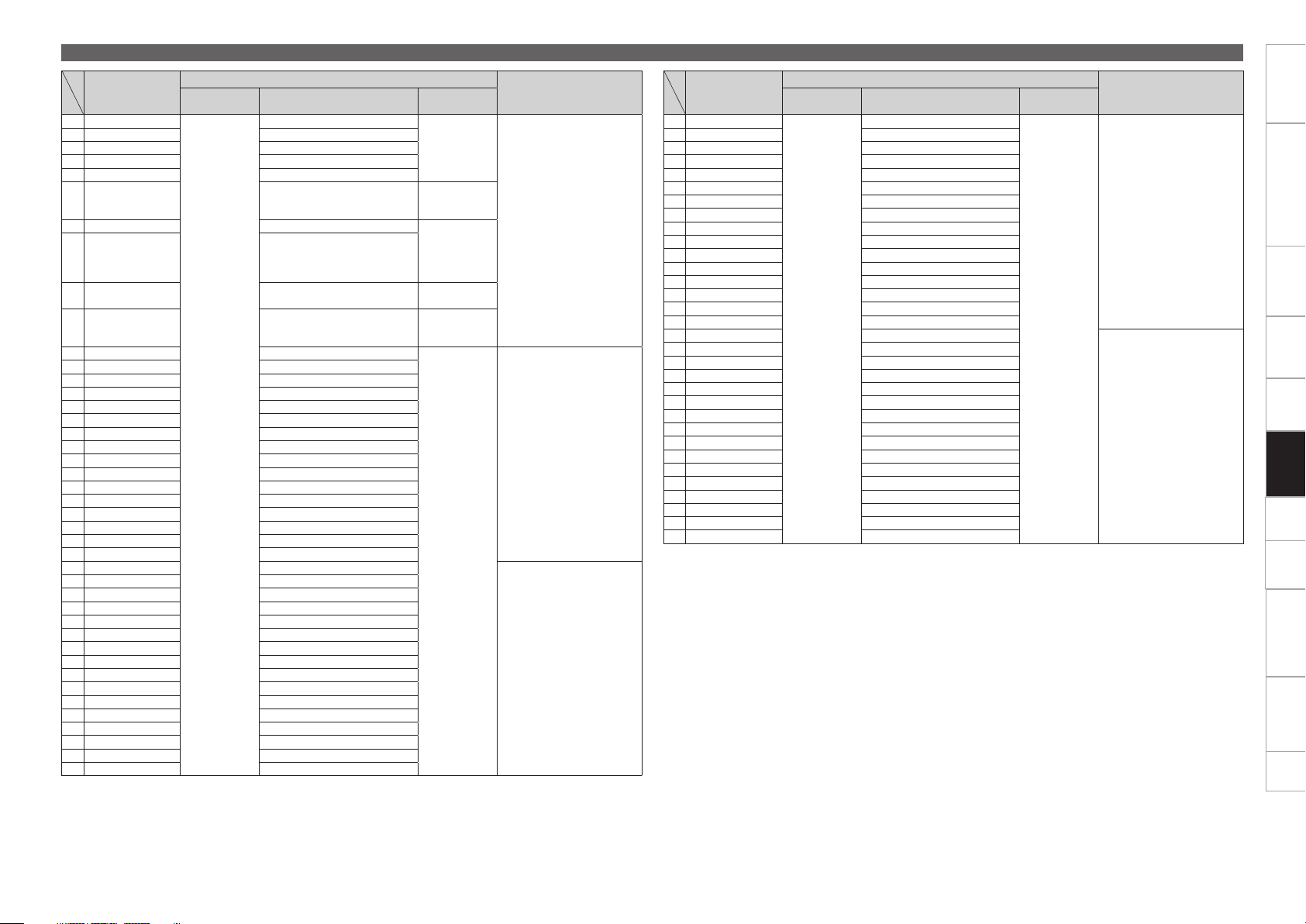
Items
(VFD Parameter)
1 Tr number MSB
2 Tr number LSB 65
3 Time mini 66
4 Time sec 67
5 Time frame 68
6 Pitch POL 69
7 Pitch MSB 70 0-99
8 Pitch LSB 71
9 Track Position
10 Point indicator
11 Segment 1-1 MSB 1
12 Segment 1-2 MSB 2
13 Segment 1-3 MSB 3
14 Segment 1-4 MSB 4
15 Segment 1-5 MSB 5
16 Segment 1-6 MSB 7
17 Segment 1-7 MSB 8
18 Segment 1-8 MSB 9
19 Segment 1-9 MSB 10
20 Segment 1-10 MSB 11
21 Segment 1-11 MSB 12
22 Segment 1-12 MSB 13
23 Segment 1-13 MSB 88
24 Segment 1-14 MSB 89
25 Segment 1-15 MSB 90
26 Segment 1-16 MSB 91
27 Segment 1-1 LSB 33
28 Segment 1-2 LSB 34
29 Segment 1-3 LSB 35
30 Segment 1-4 LSB 36
31 Segment 1-5 LSB 37
32 Segment 1-6 LSB 39
33 Segment 1-7 LSB 40
34 Segment 1-8 LSB 41
35 Segment 1-9 LSB 42
36 Segment 1-10 LSB 43
37 Segment 1-11 LSB 44
38 Segment 1-12 LSB 45
39 Segment 1-13 LSB 92
40 Segment 1-14 LSB 93
41 Segment 1-15 LSB 94
42 Segment 1-16 LSB 95
Command Number Value
CC : 0xBn
MIDI command
64
72 normal
73 reverse
58 ON
59 OFF
0-99
100-109 : “-0”
to “-9”
110 : “--”, 111
: “ ”
‘+‘ 1
‘-‘ 2
100-109 : “-0”
to “-9”
110 : “--”, 111
: “ ”
0-100 %
0 to 99
(=left edge to right
end)
0-15
‘0
ASCII+original MSB
•Segment command must be sent
to a pair in order of MSB,LSB.
ASCII+original LSB
Notes
–
Items
(VFD Parameter)
43 Segment 2-1 MSB
44 Segment 2-2 MSB 15
45 Segment 2-3 MSB 16
46 Segment 2-4 MSB 17
47 Segment 2-5 MSB 18
48 Segment 2-6 MSB 19
49 Segment 2-7 MSB 20
50 Segment 2-8 MSB 21
51 Segment 2-9 MSB 22
52 Segment 2-10 MSB 23
53 Segment 2-11 MSB 24
54 Segment 2-12 MSB 25
55 Segment 2-13 MSB 108
56 Segment 2-14 MSB 109
57 Segment 2-15 MSB 110
58 Segment 2-16 MSB 111
59 Segment 2-1 LSB 46
60 Segment 2-2 LSB 47
61 Segment 2-3 LSB 48
62 Segment 2-4 LSB 49
63 Segment 2-5 LSB 50
64 Segment 2-6 LSB 51
65 Segment 2-7 LSB 52
66 Segment 2-8 LSB 53
67 Segment 2-9 LSB 54
68 Segment 2-10 LSB 55
69 Segment 2-11 LSB 56
70 Segment 2-12 LSB 57
71 Segment 2-13 LSB 112
72 Segment 2-14 LSB 117
73 Segment 2-15 LSB 118
74 Segment 2-16 LSB 119
Command Number Value
CC : 0xBn
MIDI command
14
0-15
MIDI command list
Notes
ASCII+original MSB
ASCII+original LSB
Getting started Part names and functions Preparations Connection
Playback
MIDI Control
Others Settings
Troubleshooting Specifications Index
38
Page 45

Items
(VFD Symbol)
1 T.
2 REMAIN 2
3 ELAPSED 3
4 CONT. 4
5 SINGLE 5
6 BPM 6
7 m 7
8 s 8
9 f 9
10 Pitch dot Right 10
11 Pitch dot Center 11
12 Pitch dot Left 12
13 CD 13
14 USB 14
15 MIDI 15
16 MP3 16
17 WAV 17
18 LINK 18
19 KB 19
20 KEY ADJ. 20
21 MEMO 21
22 ( 22
23 ) 24
24 A 26
25 B 28
26 PITCH 70
27 AAC 71
28 AIFF 72
29 WFM 73
30 Scratch Ring out side 30
31 Scratch Ring in side 31
32 Touch dot 32
33 Track Position Only use 78/79 33 Total blink ON/OFF
Scratch Position 1
34
(Top right)
35 Scratch Position 2 35
36 Scratch Position 3 36
37 Scratch Position 4 37
38 Scratch Position 5 38
39 Scratch Position 6 39
40 Scratch Position 7 40
41 Scratch Position 8 41
42 Scratch Position 9 42
43 Scratch Position 10 43
44 Scratch Position 11 44
45 Scratch Position 12 45
46 Scratch Position 13 46
47 Scratch Position 14 47
48 Scratch Position 15 48
Scratch Position
49
16(Bottom)
50 Scratch Position 17 50
51 Scratch Position 18 51
Command Number Value
CC : 0xBn
MIDI command
ON TRG : 77
OFF TRG : 78
Blink ON TRG : 79
Only use 77/78
Notes
1
–
34
–
49
Items
(VFD Symbol)
52 Scratch Position 19
53 Scratch Position 20 53
54 Scratch Position 21 54
55 Scratch Position 22 55
56 Scratch Position 23 56
57 Scratch Position 24 57
58 Scratch Position 25 58
59 Scratch Position 26 59
60 Scratch Position 27 60
61 Scratch Position 28 61
62 Scratch Position 29 62
63 Scratch Position 30 63
64 Scratch Position 31 64
Scratch Position
65
32(Top)
Command Number Value
CC : 0xBn Only use 77/78
MIDI command
MIDI command list
Notes
52
–
65
Getting started Part names and functions Preparations Connection
Playback
MIDI Control
Others Settings
Troubleshooting Specifications Index
39
Page 46

Others
Memo function
•Details set in advance can be stored as memo data on a USB memory device or HDD.
When you need to configure settings in a short space of time, settings can be configured automatically
just by calling saved memo data.
•1 memo is created for 1 track, and a maximum total of 100,000 memos can be saved.
Getting started Part names and functions Preparations Connection MIDI Control
n USB memory device or HDD
•Memo data is created in the folder containing the track.
•When playing back tracks for which memo data is saved on a different player, the memo data can be
called.
Media that can be used with the memo function
The method for saving memo data differs depending on the playback media used.
n CD/CD-ROM
The memo data is saved in the memo area created on the USB memory device or HDD. Before using
the memo function, create the memo area.
For details on creating the memo area, see “Memo Area” (vpage46).
Details that can be saved as memo data
•Cue point
•Manual loop point (A/B point)
•Hot cue point 1/2/3/4
•Playback speed
•Pitch range
•Key adjust ON/OFF
•BPM (Cue point, Manual loop point (A), Hot cue point 1 – 4 BPM value)
Details that can be saved as memo data
•Cue point
•Manual loop point (A/B point)
•Hot cue point 1/2/3/4
•Playback speed
•Pitch range
•Key adjust ON/OFF
•BPM (Cue point, Manual loop point (A), Hot cue point 1 – 4 BPM value)
NOTE
Memo data cannot be saved on a USB memory device or HDD formatted in HFS+ format. Use FAT16 or
FAT32 format.
Playback
SettingsOthers
Troubleshooting Specifications Index
40
Page 47

SEL. MEMO
UTIL.
Pitch slider
Memo settings
n Memo Set
Save the setting details to memo data.
Set this unit with memo data.
1
Press MEMO UTIL.
2
“Set” is shown in the display.
Press SEL.
3
When saving is complete, the MEMO indicator lights, and
“Complete!” is shown in the display.
•When “MEMO” is shown in the display, memo data has already
been saved. To save new memo data, select “Overwrite”.
•If memo data cannot be saved, check the remaining capacity of the
USB memory device or HDD. It may not be possible to save memo
data if there is not enough spare memory.
•If the USB memory device or HDD is equipped with a security
function, check that the security is disabled.
n Memo Call
This function calls saved memo data.
Select the track that is stored with the memo data
1
that you want to call.
•When a track that has memo data stored is selected, the MEMO
indicator lights in the display.
Press MEMO UTIL.
2
“Call” is shown in the display.
Memo function
When the playback speed is called from the memo data, the PITCH
indicator flashes, and the pitch may be locked.
This is because the actual playback speed and playback speed selected
by the pitch slider differ. In order to cancel the pitch lock, adjust the
pitch slider to the same pitch as the called memo data.
n Auto Memo Load
When a track that has memo data stored is selected, the memo
data for that track is automatically called.
Set “Utility” – “Preset Setting” – “Auto Memo
1
Load” (vpage 45) to “ON”.
•The default setting is “ON”.
Select the track that is stored with the memo data
2
that you want to call.
When a track that has memo data stored is selected, the
MEMO indicator lights in the display.
Press SEL.
3
The memo data is called. When memo data call is complete,
the track switches to standby at the cue point saved in the
memo data.
Getting started Part names and functions Preparations Connection MIDI Control
Playback
SettingsOthers
Troubleshooting Specifications Index
Press SEL.
3
The saved memo data is called. When memo data call is
complete, the track switches to standby at the cue point saved
in the memo data.
41
Page 48

SEL. MEMO
UTIL.
Memo function
n Memo Clear
This function clears saved memo data.
Select the track that is stored with the memo data
1
that you want to clear.
•When a track that has memo data stored is selected, the MEMO
indicator lights in the display.
Preset recall function
Using “Preset Export” (vpage 46), preset setting details saved
on a USB memory device or HDD can be temporarily used without
overwriting on this unit.
Connect the USB memory device or HDD that
1
contains the preset to this unit.
“Preset Recall” is shown in the display.
Getting started Part names and functions Preparations Connection MIDI Control
Press MEMO UTIL.
2
“Call” is shown in the display.
Turn SEL. to select “Clear”.
3
Press SEL.
4
The MEMO indicator in the display goes out, and the memo
data is cleared.
Memo data can also be cleared in a batch using the utility mode. For
details, see “Memo Area” – “Memo Delete” (vpage 46) in the
utilities.
n Overwrite
Overwrites the memo data with the setting details.
In cue standby mode, press MEMO UTIL.
1
“Call” is shown in the display.
Turn SEL. to select “Overwrite”.
2
Press SEL.
3
The memo data is overwritten.
Turn SEL. to select “OK”.
2
Press SEL.
3
The preset settings saved on the USB memory device or HDD
connected to this unit are read.
•When the USB memory device or HDD is disconnected, this unit
returns to the state before the preset settings were read.
Playback
SettingsOthers
Troubleshooting Specifications Index
42
Page 49

How to make detailed settings
Utility menu map
For details on each setting item, see the pages in the table below.
Setting items Detailed items Description Page
Save As Def Saves the current pitch range settings, time display settings for the display, playback mode settings and key adjustment settings as
the initial settings when the power is switched on.
Preset Setting Unit No. Sets the number of this unit that ASIO driver recognizes when connected to a computer. 44
Network ID Sets the number of this unit that “engine” recognizes when connected to the network. 44
Touch Adjust Adjusting the touch sensor sensitivity of the Jog wheel. 44
Fader Mode Switches the operation for fader start for the mixer connected to this unit. 44
Panel Contrast Sets the brightness of the display and buttons and touch sensor indicator. 44
Jog Contrast Sets the brightness of the jog wheel indicator. 44
Cue Mode Switches the cue point setting mode. 45
Auto Cue Sets the detection level of the sound start point when ignoring the soundless part at the head of a track at playback. 45
Power on Play Switches power on playback on or off. 45
Relay Switches relay playback on or off. 45
Auto Loop Cnt. Sets the space between point A (start point) and point B (end point) for auto loop playback. 45
Beat Point Selects whether to use the beat grid created by “engine”. 45
Auto Memo Load Sets whether to automatically read memo data when memo data has been created for a playback track. 45
PC/MAC Sets the OS of the computer connected by USB to this unit. 45
MIDI CH Selects the MIDI channel to be used. 45
Jog Trans Int Sets the transmission interval for the JOG pulses from MIDI output. 45
Jog Ind. Color Sets the color of the jog wheel indicator light. 45
Eclipse Res. Sets the resolution for displaying the jog wheel indicator point (displaying the cue point/current playback location). 45
BPM Range Sets the BOM width for BPM search. 45
EOM Time Sets the notification for the time remaining until the end of the track being played back. 45
iPad Connect Sets the iPad connection environment. 45
Preset I/O Preset Import Imports the presets saved on a USB memory device or HDD onto this unit. 46
Preset Export Saves preset settings onto a USB memory device or HDD. 46
Memo Area Area Create Creates memo data on the USB memory device or HDD. 46
Area Delete Clears memo data created on the USB memory device or HDD. 46
Initialize USB Format Initializes the USB memory device or HDD connected to this unit. 46
Preset Init. Returns all of the preset settings to the default settings. 46
Information System Version Displays the firmware version for this unit. 46
Getting started Part names and functions Preparations Connection MIDI Control
44
Playback
Others Settings
Troubleshooting Specifications Index
43
Page 50

Utility settings
SEL. MEMO
BACK
Select the utility setting items using the following operations.
UTIL.
Getting started Part names and functions Preparations Connection MIDI Control
Save As Def.
Saves the current pitch range settings (vpage28), time display settings for the display (vpage9),
playback mode settings (vpage26) and key adjustment settings (vpage 28) as the initial settings
when the power is switched on.
Setting details
CANCEL : The screen returns to the previous screen without saving the settings.
OK : The settings are saved and the screen returns to the previous screen.
Menu operation
During standby, pause, or when a le is not selected, press and hold MEMO UTIL.
1
SEL. flashes blue, “Utility” is shown in the 1st line, and “Save As Def.” is shown in the 2nd line of
the display.
Turn SEL., and select the items you want to set.
2
Turn SEL., and the item shown in the 2nd line of the display changes.
Press SEL.
3
The selected item is entered.
•To return to the previous item, press
•To exit Utility, when the utility is being displayed, press MEMO UTIL. The screen returns to the previous
screen.
BACK.
Preset Setting
These settings are for unit operations or playback.
Setting items Setting details
Unit No.
Sets the number of this unit
that ASIO driver recognizes
when connected to a
computer.
Network ID
Sets the number of this unit
that “engine” recognizes
when connected to the
network.
Touch Adjust
Adjusting the touch sensor
sensitivity of the Jog wheel
(vpage32).
Fader Mode
Switches the operation for
fader start for the mixer
connected to this unit.
Switch this setting to match
the connected mixer.
Panel Contrast
Sets the brightness of the
display and buttons and
touch sensor indicator.
Jog Contrast
Sets the brightness of the
jog wheel indicator.
1 – 14
NOTE
When using multiple DENON DJ devices such as DN-SC2900, change this
setting so that there are no duplicate numbers.
1 – 4
NOTE
If the same “Network ID” is used between different units, they cannot be
connected on the network. If the same network IDs are duplicated, “SET
ID >>>1 (duplicated “Network ID” number)” is displayed. Set a different
“Network ID”.
Min/1/2/3/Max
1L Play/Cue : If the mixer is a 1-wire mixer, raise the fader to playback, or
lower it for cue standby.
1L Play/Pause : If the mixer is a 1-wire mixer, raise the fader to playback,
or lower it to pause.
2L Play/Cue : If the mixer is a 2-wire mixer, raise the fader to playback, or
lower it for cue standby.
2L Play/Pause : If the mixer is a 2-wire mixer, raise the fader to playback,
or lower it to pause.
0 – 4 : “0” is the brightest, and “4” is the darkest.
0 – 4 : “0” is the brightest, and “4” is the darkest.
Default settings are underlined
Playback
Others Settings
Troubleshooting Specifications Index
44
Page 51

Utility settings
Getting started Part names and functions Preparations Connection MIDI Control
Setting items Setting details
Cue Mode
Switches the cue
point setting mode
(vpage27).
Auto Cue
Sets the detection level of
the sound start point when
ignoring the soundless part
at the head of a track at
playback.
Power on Play
Switches power on playback
(vpage28) on or off.
Relay
Switches relay playback
(vpage34) on or off.
Standard : Sets the cue point by the standard method used in general
DJ products.
DENON : Sets the cue point in the same way as conventional DENON DJ
products.
OFF/–60dB/–54dB/–48dB
When set to “OFF”, playback is started from the head of the track
without skipping the soundless part.
ON : Power on playback is performed.
OFF : Power on playback is not performed.
ON : When multiple DN-SC2900 units, are connected via a network, when
a track or disc playback finishes, the next track is played back according to
the “Network ID” number.
OFF : Relay playback is not performed.
NOTE
Tracks on units that are set to “OFF” cannot be played back.
Auto Loop Cnt.
Sets the space between
point A (start point)
and point B (end point)
for auto loop playback
(vpage30).
Beat Point
Selects whether to use
the beat grid created by
“engine”.
Auto Memo Load
Sets whether to
automatically read memo
data when memo data has
been created for a playback
track.
PC/MAC
Sets the OS of the
computer connected by
USB to this unit.
1 Beat/2 Beat/4 Beat/8 Beat
ON : Uses the beat grid created by “engine”.
OFF : Does not use the beat grid created by “engine”.
ON : Memo data is automatically read.
OFF : Memo data is not automatically read.
PC : Set when the computer connected by USB to this unit runs on
Windows.
MAC : Set when the computer connected by USB to this unit runs on
Mac.
Setting items Setting details
MIDI CH
Selects the MIDI channel to
be used.
Jog Trans Int
Sets the transmission
interval for the JOG pulses
from MIDI output.
Jog Ind. Color
Sets the color of the
jog wheel indicator light
(vpage27).
Eclipse Res.
Sets the resolution for
displaying the jog wheel
indicator point (displaying
the cue point/current
playback location).
BPM Range
Sets the BPM width for
BPM search.
EOM Time
Sets the notification for the
time remaining until the end
of the track being played
back.
iPad Connect
Sets the iPad connection
environment.
1 – 16
1ms – 3ms – 10ms
Positive BLUE : On the jog wheel indicator, the playback point lights red,
the cue point lights purple, and the back ground lights blue.
Positive RED : On the jog wheel indicator, the playback point lights blue,
the cue point lights purple, and the back ground lights red.
Positive PURPLE : On the jog wheel indicator, the playback point lights
blue, the cue point lights red, and the back ground lights purple.
Negative BLUE : On the jog wheel indicator, the playback point lights
blue, the cue point lights red, and the Back ground is dark.
Negative RED : On the jog wheel indicator, the playback point lights red,
the cue point lights blue, and the back ground is dark.
Negative PURPLE : On the jog wheel indicator, the playback point lights
purple, the cue point lights blue, and the back ground is dark.
LED - 48 : Sets 48 for the resolution for displaying the jog wheel indicator
point (displaying the cue point/current playback location).
LED - 96 : Sets 96 for the resolution for displaying the jog wheel indicator
point (displaying the cue point/current playback location).
0/3/5/10
OFF/10sec/20sec/30sec/40sec/50sec/60sec
The playback position indicator flashes when the set remaining time is
exceeded.
Disable : Connection to the iPad is disabled.
Enable : Connection to the iPad is enabled. Enter the Connect ID when
connecting to the iPad.
Auto : Connection to the iPad is enabled. Only enter the Connect ID the
first time the iPad is connected. Login is performed automatically from
subsequent connections.
Even if multiple DN-SC2900 units, are connected via the network, the
iPad is connected just by entering the Connect ID once.
Playback
Others Settings
Troubleshooting Specifications Index
45
Page 52

Utility settings
Getting started Part names and functions Preparations Connection MIDI Control
Preset I/O
Presets are saved and read from a USB memory device or HDD connected to this unit.
Setting items Setting details
Preset Import
Imports the presets saved
on a USB memory device or
HDD onto this unit.
Preset Export
Saves preset settings onto
a USB memory device or
HDD.
The setting contents of presets saved to a USB memory device or HDD using “Preset Export” can be
temporarily read without being saved on this unit (vpage42 “Preset recall function”).
CANCEL : Presets are not read.
OK : Imports the presets saved on a USB memory device or HDD onto this
unit, and overwrites the settings.
CANCEL : Does not save presets.
OK : Saves presets onto a USB memory device or HDD.
Memo Area
Create memory areas and clear memo data.
Setting items Setting details
Area Create
Creates a memo area for
saving memo data.
Area Delete
All saved memo data is
cleared.
CANCEL : Memo area is not created.
OK : Memo area is created.
Connect a USB memory device or HDD to this unit in advance.
CANCEL : Memo data is not cleared.
OK : Memo data is cleared.
Just specific memos can be cleared. For details, see “Memo Clear”
(vpage42).
Initialize
Initializes the USB memory device or HDD connected to this unit and returns the preset settings of this
unit to the default settings.
Setting items Setting details
USB Format
Initializes the USB memory
device or HDD connected to
this unit.
Preset Init.
Preset settings on this unit
are returned to the default
settings.
CANCEL : Initialization is not performed.
OK : Initialization is performed.
NOTE
•When initialization is performed, all data on the USB memory device and
HDD is deleted.
•HDDs up to 2 TB in size can be formatted using this unit. Larger HDDs
are not supported.
CANCEL : Settings are not returned to the default settings.
OK : Settings are returned to the default settings.
Information
Shows information about this unit.
Setting items Setting details
System Version
Displays the firmware
version for this unit.
When the firmware version is being displayed, press SEL. to return to
the previous screen.
Playback
Others Settings
Troubleshooting Specifications Index
46
Page 53

Troubleshooting
Getting started Part names and functions Preparations Connection MIDI Control
If a problem should arise, first check the following:
1. Are the connections correct?
2. Is the set being operated as described in this owner’s manual?
3. Is the external device (DJ mixer, player or effects processor) operating correctly?
If this unit does not operate properly, check the items listed in the table below.
If the symptom is not covered on the check list, contact your dealer or service centers.
Service centers are listed at http://www.d-mpro.com or http://www.denondj.com.
Symptom Cause/Solution Page
Disc cannot be
inserted into the
loading slot.
Cannot eject disc. •Check that the power is on.
“Disc Error” is
displayed.
Power does not turn
on.
This unit does not
operate properly, or
there is no sound.
There is no sound.
Or the sound is
distorted.
There is no sound.
Or the sound is too
quiet.
•Check that the power is on.
•If a disc is already inserted, remove that disc before inserting a
new one.
•Discs cannot be ejected during playback. Stop playback before
ejecting the disc.
•The disc may be dirty or scratched. Either clean the dirt from the
disc, or replace with another disc.
•Check that the plug is inserted correctly into the wall socket, and
that the power cord is inserted into this unit.
•Check the connections for all devices.
•Check that the volume settings for the connected devices and DJ
software on the computer are properly adjusted.
•Match the settings on the unit to those on DJ software.
•Check the file sampling frequency. Only files with a sampling
frequency of 44.1 kHz can be played on this unit.
•When other USB devices are connected to the computer, connect
only the unit to the computer and check if this works.
•Check the mixer connections.
•The mixer adjustments or switching may be unsuitable. Adjust
the knobs on the mixer.
•Check the connections for all devices.
•Switch the input source switching button to the device that is
currently playing.
21
–
21
21
–
19
17 – 19
–
–
–
–
17 – 19
–
17 – 19
21
Symptom Cause/Solution Page
Sound cuts out.
Or the sound is
distorted.
Button or display
illumination is too
dark.
“Fail” is displayed. •When saving memo data, connect a USB memory device or HDD
•Exit any other applications.
•When multiple WAV files are played back simultaneously,
the playback sound may cut out depending on the computer
specifications. Try playing back 1 WAV file.
•Check the settings in “Utility” – “Preset Setting” – “Contrast”. 44
to this unit.
•If the USB memory device or HDD is equipped with a security
function, check that the security is disabled.
•Memo data cannot be saved on a USB memory device or HDD
formatted in HFS+ format. Use FAT16 or FAT32 format.
–
–
40
–
40
Playback
Others Settings
Troubleshooting
47
Specifications Index
Page 54

Specifications
n Audio
(0 dBu =0.775 Vrms, 0 dBV =1 Vrms)
Quantization: 32 bit (internal DSP process)
Sampling frequency: 44.1 kHz (at normal pitch)
Total harmonic distortion: 0.05 % or less
Signal to noise ratio: 106 dB or more
Head room 6 dB
Channel separation: 100 dB or more
Frequency response: 20 – 20 kHz, ±0.5 dB
•Analog output
Output level: 2.0 Vrms
•Digital output
Output level: 0.5 Vp-p 75Ω
n Functions
Instant start: Within 20 msec.
Variable pitch: ±6 % (0.02 % pitch)
±10 % (0.05 % pitch)
±16% (0.05 % pitch)
±100 % (0.5 % pitch)
Pitch bend: Pitch range ±6 % – ±16 % : ±32 %
Pitch range ±100 % : –99 % – +100 %
Search precision: 1/75 sec.
Folder search 9 layers (including root folder)
n General
USB MIDI input/output IN : 1 ch, OUT : 1 ch MIDI 1.0, USB B
Power supply: AC 230 V, 50 Hz
Power consumption: 30 W
Operational temperature: +5 °C – +35 °C
Operational humidity: 25 % – 85 %
Storage temperature: –20 °C – +60 °C
For the purpose of improvement, the specifications and design are subject to change without notice.
Getting started Part names and functions Preparations Connection MIDI Control
Playback
Others Settings
Troubleshooting Index
48
Specifications
Page 55

Index
Getting started Part names and functions Preparations Connection MIDI Control
v A
AC cord holder ··················································· 19
Area Create ························································ 46
Area Delete ························································ 46
ASIO Driver ·················································· 12, 14
Auto BPM counter ············································· 31
Auto Cue ···························································· 45
Auto Loop Cnt. ··················································· 45
Auto loop playback ············································· 30
Auto Memo Load ··············································· 45
v B
Beat Point ··························································· 45
BPM ··································································· 31
BPM Range ························································ 45
BPM SYNC function ··········································· 34
v C
Cable
Coaxial cable ···················································· 17
Ethernet cable·················································· 17
RCA cable ························································ 17
Stereo mini cable ············································· 17
USB cable ························································ 17
CD-R/CD-RW ························································ 4
Connection
Computer ··················································· 18, 19
DJ mixer ·············································· 17, 18, 19
HDD ··························································· 17, 18
Power cord ······················································ 19
USB memory device ·································· 17, 18
Cue Mode ·························································· 45
Cue point ···························································· 27
v D
Display ·································································· 9
v E
Eclipse Res. ························································ 45
EOM Time ·························································· 45
v F
Fader Mode ························································ 44
Fast forward/Rewind ·········································· 26
Finalization ···························································· 4
Front panel ························································· 11
v H
Hot cue playback ················································ 30
Hot list ································································ 31
v I
Information ························································· 46
Initialize ······························································ 46
iPad Connect ······················································ 45
v J
Jog Contrast ······················································· 44
Jog Ind. Color ··············································· 27, 45
Jog Trans Int ······················································ 45
v L
Loop point ·························································· 29
v M
Manual loop playback ········································· 29
Memo Area ························································ 46
Memo function ··················································· 40
MIDI CH ····························································· 45
MIDI command ············································ 35, 36
MIDI layer ··························································· 35
Music CDs ···························································· 4
v N
Network ID ························································· 44
v P
Panel Contrast ···················································· 44
Pause ································································· 26
PC/MAC ····························································· 45
Pitch bend function ············································ 28
Playback ····························································· 26
CD ···································································· 20
CD-R ································································ 21
CD-ROM ·························································· 21
CD-RW ····························································· 21
HDD ································································· 22
Network ····················································· 23, 33
USB memory device ········································ 22
Playback mode ··················································· 26
Playback speed ·················································· 28
Power on Play ···················································· 45
Power on playback ············································· 28
Preset Export ····················································· 46
Preset Import ····················································· 46
Preset Init. ·························································· 46
Preset I/O ··························································· 46
Preset recall function ········································· 42
Preset Setting ···················································· 44
v R
Rear panel ·························································· 11
Relay ·································································· 45
Relay playback ···················································· 34
Reverse playback ··············································· 32
v S
Save As Def. ······················································ 44
Scratch playback ················································ 31
Searching ··························································· 24
SLIP function ······················································ 32
System Version ·················································· 46
v T
Top panel ······························································ 5
Torque Adjust ····················································· 32
Touch Adjust ················································ 32, 44
TRAKTOR LE 2 ········································· 7, 10, 15
Turning the power off ········································ 20
Turning the power on ········································· 20
v U
Unit No. ······························································ 44
USB Format ························································ 46
Utility ·································································· 44
Playback
Others Settings
Troubleshooting Specifications
49
Index
Page 56

Dimensions
Unit: mm
Getting started Part names and functions Preparations Connection MIDI Control
42,0
55,0
326,0
366,0
74,016,0
90,0
123,8
280,0
44,0
Playback
Others Settings
Troubleshooting Specifications Index
38,0
Weight: 4.35 kg
250,0
38,0
50
Page 57

V00
3525 10117 00AS
 Loading...