

Page 1
16
INTRODUCTION
This is a conditioner of the air-to-air type composed of two units: one internal (which operates
inside the room) and the other external (to be
installed outside). These two units are joined
together by a sheathing (of about 3 m.) containing
the refrigerant pipes, electrical power cables and
condensation-discharge tube.
TECHNICAL FEATURES
Power supply
voltage See the features plate
Maximum absorbed power “
Cooling capacity* “
Max. air flow rate 560 m
3
/h
Flexible tube length 3 m
Sheathing section 20 x 44 mm
Dimensions: indoor unit
• length 560 mm
• height 735 mm
• depth 355 mm
• weight 44 kg
Dimensions: outdoor unit
• length 570 mm
• height 480 mm
• depth 260 mm
• weight 18 kg
* Standard conditioning:
Inside temperature 27°C
relative humidity: 47%
Outside temperature 35°C
relative humidity: 41%
Carefully read this instructions
booklet before installing or
using this appliance.
Only by doing so will you have
the best results and enjoy the
greatest safety when using the
appliance. Please pay particular
attention to the warnings on
page 28.
OPERATIONAL AIRCONDITIONING LIMITS
Room temperature 21 ÷ 32°C
Outside temperature 21 ÷ 43°C
GB-5750004200 11-02-2004 9:12 Pagina 16
Page 2
17
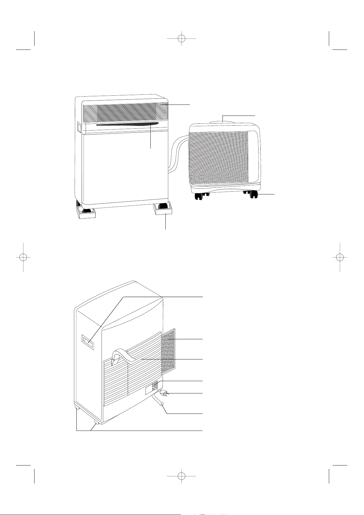
DESCRIPTION
Air delivery grille
External unit handle
Forced operations
button
Castor stop
INTERNAL UNIT
EXTERNAL UNIT
INTERNAL UNIT
Carrying handle
Removable filter
Air intake grille
Power cable compartment
Power cable
Condensation drainage tube
Castors
Castors
GB-5750004200 11-02-2004 9:12 Pagina 17
Page 3
18
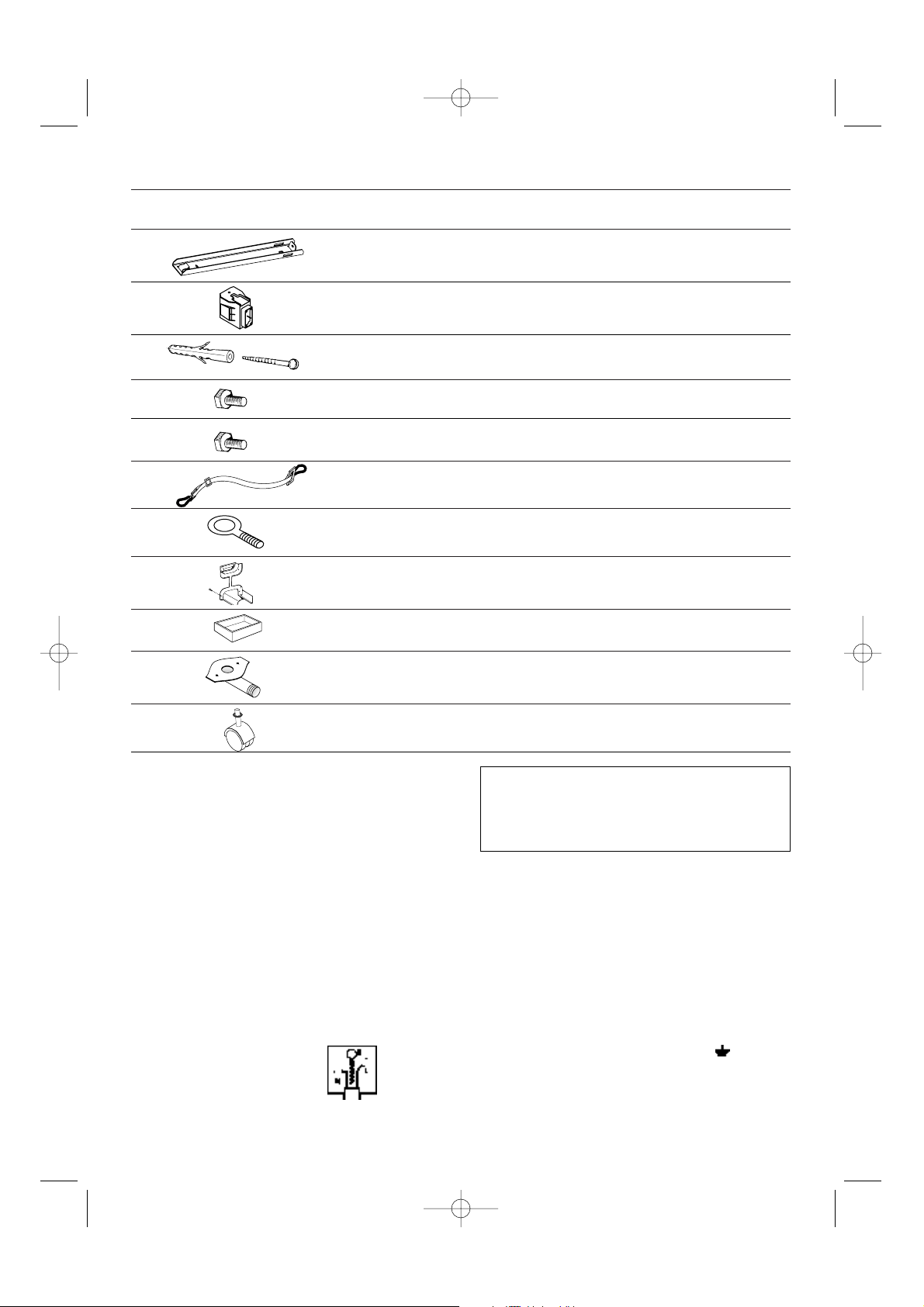
ACCESSORIES
DRAWING DESCRIPTION NO. PIECES PROVIDED
Wall-attachment bracket 2
Anchor screws + screws ø 6 mm
4
Screws M4x25 mm 4
Belt with hooks 2
Screw eye for a belt 2
Sheathing frame 1
Castor stop
2
Drain connection for condensation
with seal and two 4.2 penetrating
screws
1
TECHNICAL SERVICE
Keep the list of Technical Service Centres in a
safe place and check to find the closest Centre
(though we hope you will never have to seek their
help).
This appliance has been fitted with an HE (High
Efficiency) system for low energy consumption,
so after turning the appliance on you may have to
wait a few minutes for cool air to begin circulating.
Castors for the external unit and
washers
4
WARNING - THIS APPLIANCE MUST BE EARTHED
IMPORTANT
The wires in the mains lead are coloured in accordance with the
following code:
Green and yellow: Earth
Blue: Neutral
Brown: Live
As the colours of the wires in the mains lead may not correspond with
the coloured markings identifying the terminals in your plug, proceed
as follows:
The green and yellow wire must be connected to the terminal in the
plug marked with the letter E or the earth symbol or coloured
green or green and yellow.
The blue wire must be connected to the terminal marked with the letter
N or coloured black.
The brown wire must be connected to the terminal marked with the
letter L or coloured red.
ELECTRICAL CONNECTION (U.K. ONLY)
A) If your appliance comes fitted with a plug, it will incorporate a 13
Amp fuse. If it does not fit your socket, the plug should be cut off
from the mains lead, and an appropriate plug fitted, as below.
WARNING: Very carefully dispose of the cut off plug after removing the fuse: do not insert in a 13 Amp socket elsewhere in the
house as this could cause a shock hazard.
With alternative plugs not incorporating a fuse, the circuit must be
protected by a 15 Amp fuse.
If the plug is a moulded-on type, the fuse cover must be re-fitted
when changing the fuse using a 13 Amp Asta approved fuse to BS
1362. In the event of losing the fuse cover, the plug must NOT be
used until a replacement fuse cover can be obtained from your
nearest electrical dealer. The colour of the correct replacement
fuse cover is that as marked on the base of the plug.
B) If your appliance is not fitted with a plug, please follow the instruc-
tions provided below:
Support block for external unit
2
Screws M6 mm 2
GB-5750004200 11-02-2004 9:12 Pagina 18
Page 4
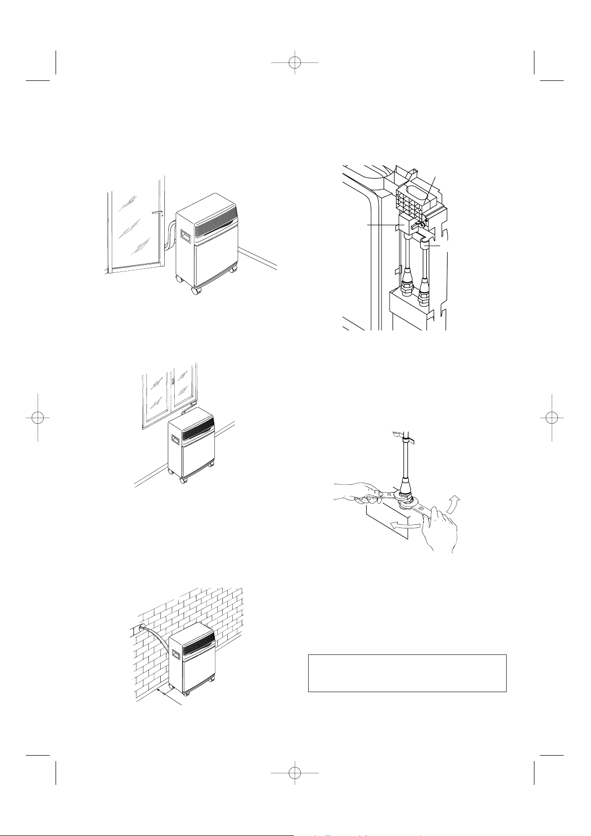
INSTALLATION
The sheathing that connects the external to the
internal unit may pass:
a) through a slightly-open window or door;
b) through a small hole (5.5 cm x 2.5 cm) drilled
in the lower part of a door or in a window
frame by using the frame provided.
USE OF RAPID COUPLINGS
In addition to the methods described above, the
sheathing that joins the external to the internal unit
may also be drawn through a hole (about 6 cm. in
diameter) drilled in a wall linked to the outside.
In this case, the hook-ups with the external unit
must be disconnected as follows:
1) Remove the plug from the electric outlet;
2) Remove the handle by loosening the two
screws and then slipping off the facing.
3) Remove the U bolt by loosening the two
screws.
4) Remove the sheath stop by loosening the two
screws.
5) Using a 24-version wrench, unscrew the union
on the coupling. At the same time, hold the end
of the flexible tube tight by using a 21-version
wrench. Repeat this operation for the second
union using a 24- and a 19-version wrench.
6) Disconnect the condensation tube from the
rubber holder.
7) Loosen the shield’s two self-threading screws
and disconnect the electric hook-up unit.
The path of the connecting sheath should be as
straight as possible, without sharp curves or
kinks.
19
ø6
cm 30
SHEATH STOP
ELECTRIC
HOOK-UP
SHIELD
U BOLT
GB-5750004200 11-02-2004 9:12 Pagina 19
Page 5
To re-connect the detached ends of the sheath to
the internal unit, you must repeat operations 1
through 7 in reverse order, being careful to
observe the following precautions:
• Before drawing the sheath through the hole in
the wall, you should wrap the threaded ends of
the speedy couplings with friction tape or the
like as a protective measure.
• Fit the upper two cooling junctures into the two
lower ones and hand-screw them several turns
while checking to be certain they are well-fitted, and then tighten them with the wrenches
used earlier.
• After having hooked up the two cooling junctures, tighten the U bolts.
• Check the grip on the cooling junctures by wetting the joints with a little soapy water.
No bubbles should appear.
Caution:
We recommend that the disconnecting and connecting of the rapid couplings be carried out only
by qualified technicians.
INTERNAL UNIT
Install the internal unit inside the room to be airconditioned. This is usually done under a window
or at least close to an outside wall.
The internal unit must be placed “on the level”,
with the help of the castor-stops provided. No
obstacles should block this unit’s in-take (suction
grille) or out-take (outlet grille) areas.
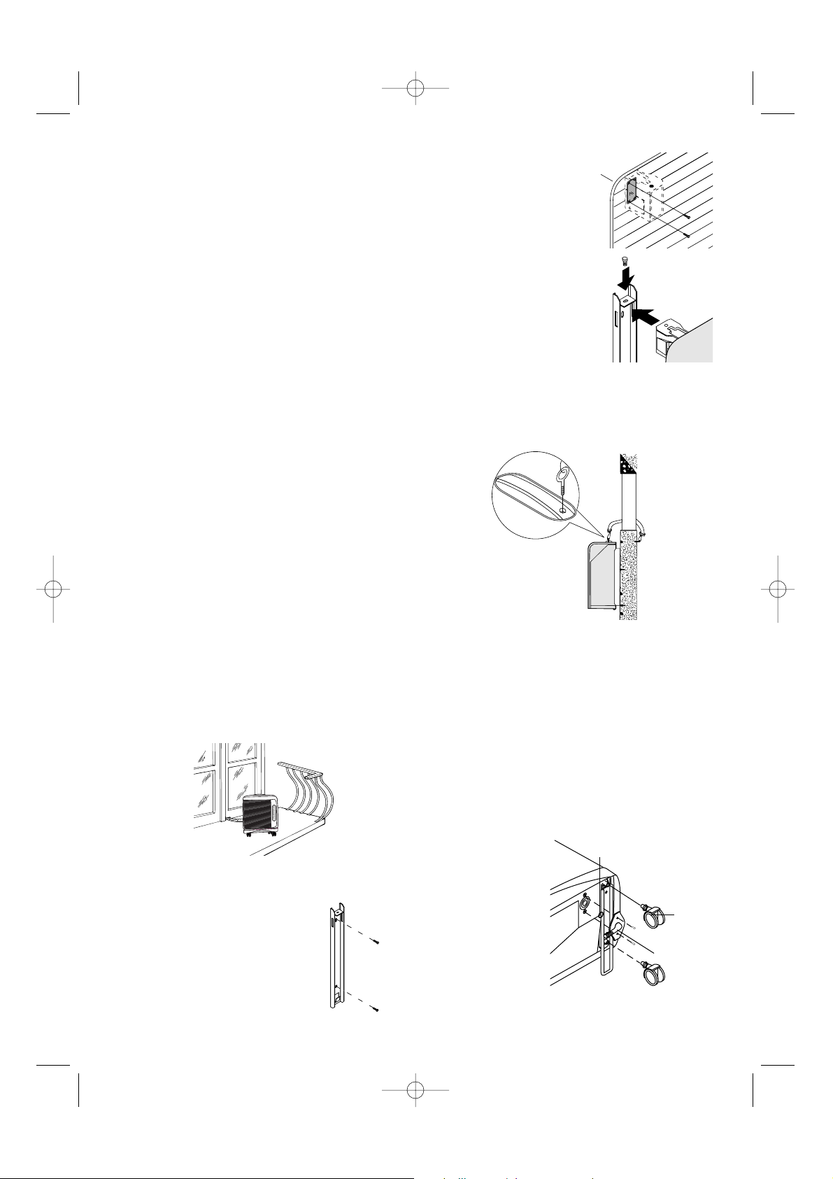
EXTERNAL UNIT
The external unit may be placed on a terrace or
balcony, in which case the brackets need not be
used.
The external unit can be attached to a wall with the
accessories included as follows:
1) Attach the bracket to the
wall while taking care to
place it as indicated in the
drawing. Use the included
template located on the
plastic cover in order to drill
the holes.
2) Screw the support blocks
to the external unit with
the included M4mm
screws while taking care
to place them so that the
hole for the screws is on
the upper side.
3) Attach the external unit to
the bracket by means of
the M6mm screws.
For temporary installation it is possible to hang the
external unit as illustrated in the drawing. In this
case, use the included straps by attaching them to
the eye hooks. Before inserting the eye hooks
remove the rubber plugs.
The external unit may be installed above or at the
same height as the internal unit, on the condition
that the difference is no more than 1.5 m.
The suction and air-delivery portions of external
unit must not be blocked by obstacles of any
nature.
The distance between the back of the appliance
and the wall must be six (6) cm.
The condensation which forms while this appliance is running (summertime operations) is disposed of by evaporation from the external unit.
If the humidity is too high (in special cases), you
must use the drainage coupling provided to get rid
of condensation. This device must be mounted on
the bottom of the
external unit (see
drawing) after the
rubber plug has
been removed.
We strongly recommend that you protect the external unit
from rain, snow,
direct sunlight and
water dripping from
the roof.
20
Castor
Drainage
Coupling
Gasket
GB-5750004200 11-02-2004 9:12 Pagina 20
2
1
Page 6

ELECTRICAL CONNECTION
Before plugging in check that:
• the mains supply corresponds to the value
shown in the specifications table;
• the socket and the mains lead correspond to
the power requirements of the appliance;
• the socket is suited to the plug , otherwise
have the socket replaced;
• the socket is properly grounded. The manu-
factures cannot be held responsible for any
damages due to failure in following normal
safety procedures.
Replacement of the power cable must be carried out by qualified personnel.
A LAST LOOK AT THE ROOM
There are several precautions you should keep in
mind so as to get the best use out of your air-conditioner:
• Close the doors and windows in the room to be
air-conditioned (except for temporary installation, in which case a window must be left partially open).
• In order to insure low-cost operations, protect
the room from direct sunlight by drawing the
curtains and/or by partially lowering or closing
the shutters or blinds
• Do not place objects atop the air-conditioner.
• Do not block the suction and air delivery areas.
• Make certain there are no heating sources in
the room.
IN THIS WAY, YOUR AIR-CONDITIONER IS
READY TO WORK, so now let’s familiarise ourselves with its controls.
21
Close the windows
Close the doors
Draw the curtains
Lower (or partially close) the shutters
Do not cover
This appliance is equipped with a safety system which prevents the compressor from turning on
until at least three (3) minutes have elapsed since the appliance was last turned off.
GB-5750004200 11-02-2004 9:12 Pagina 21
Page 7

22
BUTTONS AND INDICATORS ON THE INTERNAL UNIT
FORCED
OPERATION
BUTTON
GREEN LED YELLOW LED RED LED
SIGNAL RECEIVER
THE LEDS
Led displays come on depending on the selected function or as warning of possible anomalies.
ANOMALY RED LIGHT YELLOW LIGHT GREEN LIGHT
ALARM
blinking blinking blinking
FUNZIONE RED LIGHT YELLOW LIGHT GREEN LIGHT
OFF
---
AIR-CONDITIONING
--on
DEHUMIDIFYING
on - on
PURIFYING
- on -
SMART
TIMER
As soon as this function is selected, all LED displays will remain on for some seconds until the control unit
selects which mode to function in (whether air-conditioning, dehumidifier, fan or heater).
TIMER - if the TIMER mode is selected, the indicator lights remain on even when the appliance is off.
See "Troubleshooting" on page 29.
FORCED OPERATIONS
This is a way of operating to be selected if there are problems with the remote control (broken or lost, or
the batteries run-down).
Press the Forced operation button until the required mode is selected (air conditioning, dehumidifying, fan,
smart, off). Refer to the indicator lights and the table below to identify the mode selected. For each mode
selected, the appliance will automatically choose the optimum values for maximum comfort.
GB-5750004200 11-02-2004 9:12 Pagina 22
Page 8

23
REMOTE CONTROL
Inserting the batteries
• Slide the cover as shown in figure.
• Insert two new batteries (not rechargeable)
making sure the (+) and (-) are in the correct
positions.
• Put the cover back on, letting it slide into its original position.
• The Display will show all of the remote control's symbols for several seconds.
Note: WE SUGGEST USING ALKALINE BAT-
TERIES (LR03).
If the remote control is to be replaced or
thrown away, the batteries must be removed
and disposed of in accordance with the current laws as it represents an environmental
hazard.
When the remote control unit batteries are replaced, the air-conditioning indicator and heating
indicator will flash alternately
on the remote control unit liquid crystal display.
To set the remote control unit correctly, while
is displayed, press any button.
If you do not press a button within 12 seconds, the
remote control unit will also make the heating
mode available, despite the fact that this function
is not available with this appliance.
PROPER USE
• Point the remote control unit towards the airconditioning unit signal receiver.
• Maximum distance: about seven (7) metres
(without any obstacle between remote control
and receiver).
• The remote control must be handled with
great care: do not drop it, expose it to direct
sunlight, or leave it close to heat sources.
GB-5750004200 11-02-2004 9:12 Pagina 23
Page 9

24
IL DISPLAY
Signal transmission
Air conditioning indicator
Dehumidifying indicator
Fan indicator
Heating indicator (mode not available
with this appliance)
SUPER air conditioning indicator
SMART indicator
SLEEP indicator
Automatic fan speed
High fan speed
Medium fan speed
Low fan speed
Regulates temperature in SMART or
Dehumidifying mode.
A. MODE button
Selects the operating mode (air conditioning, dehumidifying, fan).
B. ROOM TEMPERATURE buttons
Set room temperature or programme the
timer.
Low
High
Low
High
High
High
Low
High
Low
High
High
Low
High
Low
High
High
High
C. FAN button ( )
Sets fan speed to automatic, high,
medium or low in sequence.
D. TIMER button
Sets or cancels the timer.
E. SMART button ( )
When this button is pressed, the appliance
automatically establishes the most suitable operating mode for maximum
comfort.
F. SUPER button ( )
Starts or stops rapid cooling (in the rapid
cooling mode, the fan operates at high
speed with the temperature automatically set at 18°C).
G. SLEEP button ( )
Sets or cancels the automatic SLEEP function.
H. SWING button (wall mounted models only)
Starts or stops swing of the air distribution
vertical adjustment fins and sets the required air flow direction upwards or
downwards.
I. ON/OFF button
Press this button to turn the appliance on
and off. NB: the settings are displayed
even when the air conditioner is off.
Low
High
High
High
Low
High
LowLow
HighHigh
High
GB-5750004200 11-02-2004 9:12 Pagina 24
Page 10

25
AIR-CONDITIONING MODE
• Press the button to turn the appliance on.
•Abeep indicates that the air-conditioning unit is on and the
symbol flashes on the display
• Press the MODE button a number of times until the air-conditioning
symbol appears on the display.
• Now set the temperature using the buttons.
•To select fan speed, press the FAN button repeatedly until the required
fan speed is selected (automatic, high, medium, low).
NB: in air-conditioning mode, the appliance automatically removes
excess moisture from the atmosphere.
DEHUMIDIFYING MODE
• Activate this function when humidity is high.
• Press the button to turn the appliance on. A beep indicates that the
air-conditioning unit is on and the symbol flashes on the
display.
• Press the MODE button a number of times until the dehumidifying symbol appears on the display.
• Use the buttons to set the required level of dehumidifying.
The symbol is displayed .
• Press the button to increase the dehumidifying level and the
button to reduce it.
• In dehumidifying mode, fan speed is selected by the appliance automatically.
FAN MODE
On humid but not particularly hot days, the fan function alone may be adequate.
• Press the button. A beep indicates that the air-conditioning unit is
on and the symbol flashes on the display.
• Press the MODE button a number of times until the fan symbol
appears on the display.
• Once fan mode has been selected, press the FAN button until the
required speed is reached (low, medium, high).
LowLow
HighHigh
LowLow
HighHigh
GB-5750004200 11-02-2004 9:12 Pagina 25
C
24
Page 11

26
SMART MODE
In SMART mode, the air-conditioning unit decides the best way to operate
to guarantee maximum comfort.
• Press the button to turn the appliance on. A beep indicates that the
air-conditioning unit is on and the symbol flashes on the display.
• Press the SMART button. The appliance functions automatically and
the symbol appears on the display.
NB: in SMART mode, temperature is controlled automatically.
However, if the required temperature has not yet been reached, it can
be reduced or increased by a maximum of 2° C by pressing the
buttons.
.
It should be pointed out that when the automatic ventilation functions are
activated, the appliance itself will choose the proper speed.
AUTOMATIC SLEEP MODE
The automatic SLEEP mode is ideal for the night-time as it enables operation of the air-conditioning unit in any of the modes (air-conditioning,
dehumidifying, fan or SMART) to be gradually reduced until it shuts down
completely (after eight hours). To select SLEEP mode, proceed as follows:
• Press the button to turn the appliance on.
•Abeep indicates that the air-conditioning unit is on and the symbol
flashes on the display.
• Press the MODE button a number of times until the symbol of the function required appears on the display.
• Then select the required temperature by pressing the buttons.
• Now press the SLEEP button to set the night function. The symbol
is displayed. Press the SLEEP button again to go back to the previous
mode. In this mode, the fan operates at low speed.
N.B: The night-time function makes it possible to keep a room at a perfect temperature,
thus preventing an excessive rise or a drop in temperature while the silent operation is in
effect. The air-flow will decrease, while the room temperature will vary gradually to provide
the ideal condition: the temperature will increase by 1° C. after 60 minutes and by 2° C.
after two hour (it goes off altogether after 8 hours).
Low
High
GB-5750004200 11-02-2004 9:12 Pagina 26
High
Low
C
Page 12

27
SUPER MODE
SUPER mode is used to turn rapid cooling on or off. The fan is set to
high speed and the temperature is automatically set to 18° C.
To select SUPER mode, proceed as follows:
• Press the button to turn the appliance on. A beep indicates that
the air-conditioning unit is on and the symbol flashes on the display.
• Press the SUPER button to set the mode. The symbol is displayed.
•To go back to the previous mode, press the SUPER button again.
PROGRAMMING THE TIMER
After selecting the required operating mode, activate the timer by pressing
the TIMER button when you go out in the morning to obtain a comfortable
room temperature at the time you will be coming home.
Programming the turn-off function
•With the air-conditioning unit on, press the TIMER button. The time is
displayed and the "h" symbol flashes. Set the time when you want the
appliance to go off using the buttons (from 30 minutes to 24
hours).
• Press the TIMER button again to confirm the selection. A countdown of
the time left is displayed.
• At the end of the set time the appliance goes off automatically.
During the first ten hours, you can select half hour intervals. For times
greater than ten hours, one hour intervals can be selected.
•To cancel the set time, press the TIMER button again. You will hear a
beep.
Programming the ON function
•With the air-conditioning unit off, press the TIMER button. The time is
displayed and the "h" symbol flashes. Set the time when you want the
appliance to come on using the buttons (from 30 minutes to 24
hours).
• Press the TIMER button again to confirm the selection. The three indicator lights on the air-conditioning unit come on.
• At the end of the set time the appliance comes on automatically.
During the first ten hours, you can select half hour intervals. For times
greater than ten hours, one hour intervals can be selected.
•To cancel the set time, press the TIMER button again. You will hear a
beep and the three indicator lights on the air-conditioning unit will go
off.
GB-5750004200 11-02-2004 9:12 Pagina 27
h
Page 13

28
MAINTENANCE
Always pull the plug from the electrical outlet
before beginning any cleaning or maintenance
operations.
For safety reasons, never wash the air-conditioner with water.
CLEANING THE UNIT
Clean your air-conditioner with a damp cloth and
then wipe it with a dry cloth.
Precautions:
Never use gasoline, alcohol or solvents to clean
this appliance. Never spray it with insecticide or
similar liquids, because the paint might then peel
away and the plastic portions might lose their true
shape.
CLEANING THE AIR FILTER
• If the air filter gets dirty, it will be difficult for the
air to circulate and the air-conditioner will lose
much of its efficiency, thus leading to about an
8% increase in electrical consumption. For this
reason, it is a good idea to clean the filter
• Remove the air filter as shown below.
• Use a vacuum cleaner to remove the dust on
the filter. If the filter is very dirty, dip it in warm
water (of less than 40° C.) and rinse it several
times. After having washed the filter, let it dry
completely before putting it back in place.
CHECKS TO MAKE AT A SEASON’S
BEGINNING
Check to make certain that the power cable and
the electrical outlet are in perfect condition and
that there is a suitable earthing system.
Give strict observance to all installation norms.
WORK TO BE DONE AT A SEASON’S END
Turn off the air-conditioner.
Clean the filter and dry it before putting it back in
place.
Cover the air-conditioner with a plastic bag to
keep the appliance from getting dusty.
Remove the batteries from the remote control
device.
IMPORTANT SAFEGUARDS
• This appliance has been built to air-condition,
dehumidify and ventilate rooms in the home
and must not be used for other purposes.
• Changing or altering the features of this feature in any way is dangerous.
• If repairs are needed, always contact only a
Technical Assistance Centre authorised by the
manufacturer. Repairs by unauthorised personnel may be inherently dangerous.
• This appliance must be connected to an efficient “earthing” system. Have your electrical
system checked out by a qualified electrician.
•Avoid using extension cords for the electric
feed cable.
• Before any cleaning or maintenance, always
pull the plug from its electric outlet.
• Never pull on the feed cable to move this
equipment.
• Do not install this appliance in rooms where
the air may contain gas, oil or sulphur or in the
close proximity of a heat source.
• Never place heavy or hot objects on this airconditioner.
• Clean the air filter at least once a week.
• When being moved, this appliance must be
kept in an upright position or placed carefully
on one side.
• Do not make use of heating equipment in the
close proximity of this air-conditioner.
After having moved this appliance, wait for at
least one (1) hour before turning it on again.
Filter
GB-5750004200 11-02-2004 9:12 Pagina 28
Page 14

29
IF SOMETHING GOES WRONG
Most malfunctions are caused by a very minor and easily solved problem. So carefully check this list before
contacting the Authorised Technical Service Centre in your area.
PROBLEMS CAUSES REMEDIES
The air-conditioning
is not working
• Lack of electrical power
• The plug has not been inserted
• The timer has been set improperly
•Wait
• Insert the plug in the electrical outlet
• Set the timer correctly
The cooling is insufficient
• Dirty air filter
• Room too warm
•Temperature set incorrectly
• The air in-take & out-take grilles are blocked
• Clean the air filter
•Wait for the cooling to begin
• Set the temperature correctly
• Clean the grilles
• Clean the air filter
Strange odour in the
room
• Dirty air filter
Build-up of condensation from the airconditioner’s internal unit
• Internal unit water tray full
• Appliance not installed correctly
• Drain the water through the condensation tube located on the
back of the unit
• See p. 21 for information on proper installing
Remote control signals are weak or
inexistent
• Batteries run down
• Batteries may be inserted incorrectly
• Change the batteries
• Check the batteries’ (+) and (-)
poles
The air-conditioner does
not start working until 3
min. after it has been
turned on
• The safety device will click on • Wait for 3 minutes to pass
SERVICE
If the problem persists after these checks have been made, contact your nearest authorised Technical
Service Centre. Specify the model you own and the type of defect encountered.
The compressor
turns on and off
intermittently
• The air-conditioner is operating as a dehumidifier
• The anti-icing safety device switches on
GB-5750004200 11-02-2004 9:12 Pagina 29
 Loading...