

Page 1
FORNI MICROONDE / MICROW AVE OVENS
MIKROWELLENGERÄTE / FOURS A MICRONDES
DATITECNICI/TECHNICALDATA/TECHNISCHEDATEN
DONNEESTECHNIQUES/DATOSTECNICOS
HORNO MICROONDAS
DE' LONGHI MW425
(INT)
Voltaggio / Voltage / Spannung / Voltage / Voltaje
Max.potenza assorbita / Max. input power / Max.Leistungsaufnahme
Max.puissance absorbée / Max.potencia absorbida
Potenza microonde / Microwave output / Mikrowellenleistung
Puissance de sortie microondes / Potencia cedida microondas
Magnetron
- termostato sicurezza / safety thermostat / Sicherheitsthermostat
thermostat de sécurité / Termostato de seguridad
Commutatore / Change over switch / Umschalter / Commutateur / Conmutador
Resistenza grill / Grill heating element / Grill-Heizkörper
Elément chauffant gril / Resistencia grill
Termostato grill / Grill thermostat / Grill-Thermostat
Thermostat gril / Termostato del grill
Trasformatore / Transformer / Transformator / Transformateur / Transformador
- avvolgimento primario / primary winding / Wicklung primär
bobinage primaire / envolvimiento primario
- avvolgimento secondario / secondary winding / Wicklung sekundär
bobinage secondaire / envolvimiento secondario
- avvolgimento filamento / filament winding / Glühfaden-Wicklung
bobinage filament / envolvimiento filamento
V/Hz
W
W
Type
Type
°C
Type
W
°C
Type
V/W
V/W
230-50
2250
750
Toshiba 2M240J-AN
Texas PK1
145
Elettronico
1000
75
DeoBo
DB-80DEA
230 - 2.3
2050 - 115
3.2
V
Condensatore / Capacitor / Kondensator / Condensateur / Condensador
Diodo / Diode / Diode / Diode / Diodo
Ventilatore / Ventilator / Ventilator/Ventilateur/ Ventilador
- avvolgimento / winding / Wicklung / bobinage / envolvimiento
Contaminuti / Timer / Zeitschaltuhr / Programmateur / Programador
- avvolgimento / winding / Wicklung / bobinage / envolvimiento
Microinterruttori / Microswitches / Mikroschalter
Microrupteurs / Microinterruptores
Diodo protezione/Protection diode/Schutzdiode
Diode de protection/Diodo de protecciòn
Motore piatto / Turntable motor / Drehteller-Motor
Moteur plateau tournant / Motor del plato giratorio
Lampada / Lamp / Lampe / lampe / Lámpara
Fusibile / Fuse / Schmelzsicherung / Fusible / Fusibile
mF
Type
Type / W
W
Type
Type
V/A
Type
Type
W
V/W
0.95
SankenHVR1XóFci HV 03-09
Johnson SP-6309-230 / 25
262.5
Elettronico
SodecoóSaiaó Xgaw óCrouzet
250/12
FCI HV 06X1P5
JAEST-16MN73SYAWF
3 / 2.5
230/25
EM8óEF8 Fusit or Omega
A
1
SCHEDA TECNICA 97048
Page 2
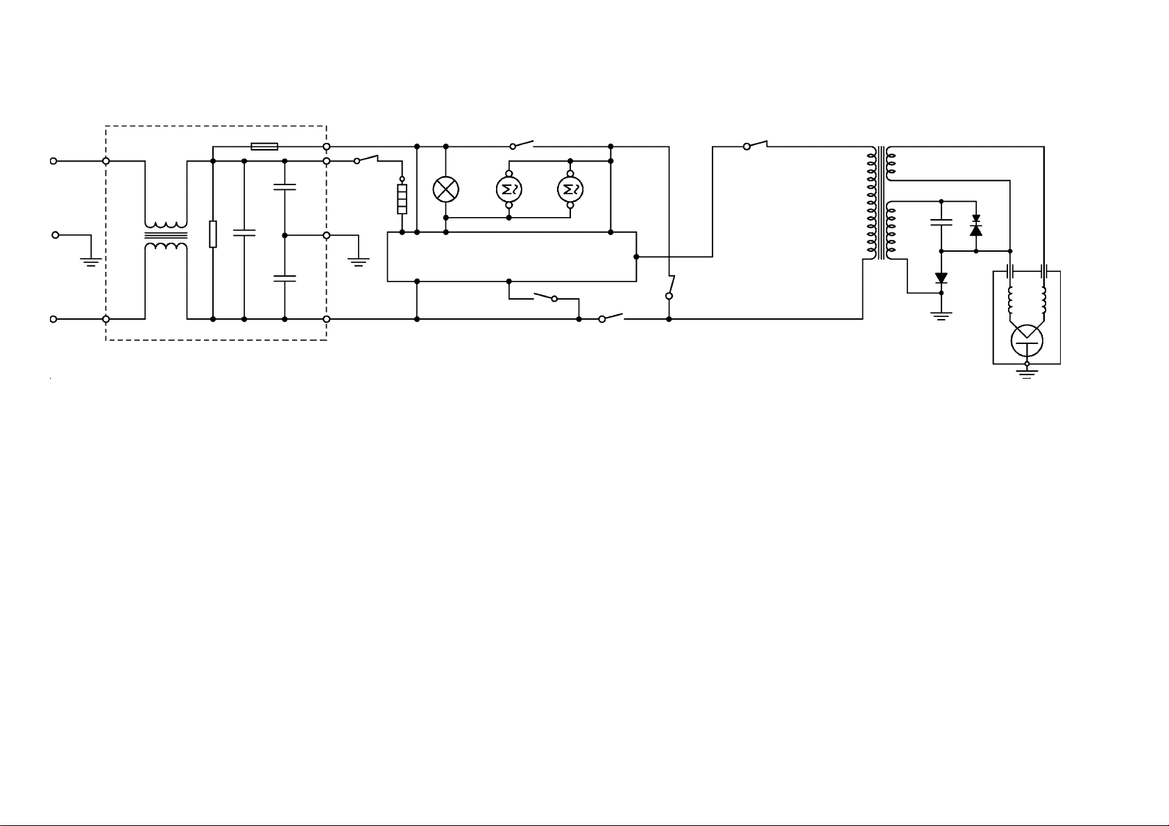
SCHEMA ELETTRICO / ELECTRIC DIAGRAM / SCHALTPLAN
SCHEMA ELECTRIQUE / ESQUEMA ELECTRICO
NF
THG
RG
F7 F2 F8-F9
OL FM
EC
F1 F3
2
Porta aperta / Door open / Tür auf / Porte ouverte / Puerta abierta
SEC
LOG
DM
F5-F6
PRI
F4
MON
TH.MGT
HVT
HVC
PDX
HVD
MGT
LEGENDA -LEGEND-ZEICHENERKLÄRUNG-LEGENDE-LEGENDA
CA Cavoalimentazione Power supply cable Netzkabel Cabled'alimentation Cabled'alimentasiòn
DM Motorepiatto rotante Turntable motor Drehteller-Motor Moteur plateau tournant Motor del plato giratorio
EC Controllo elettronico Electronic control Elektronisch Kontrolle Controle èlectronique Control electrònico
FM Ventilatore magnetron Magnetron ventilator Magnetron-Ventilator Ventilateur magnetron Ventilador magnetron
HVC Condensatore alta tensione High voltage capacitor Hochspannungskondensator Condensateur h.t. Condensador a.t.
HVD Diodo rettificatore a.t. High voltage retifier diode Hochspannungsdiode Diode h.t. Diodo a.t.
HVT Trasformatore alta tensione High voltage transformer Hochspannungstransformator Transformateur h.t. Transformador a.t
LOG Micronterruttore logico Logical microswitch Mikroschalter logisch Microrupteur logique Microinterruptor lògico
MGT Magnetron Magnetron Magnetron Magnetron Magnetron
MON Microinterruttore monitor Monitor microswitch Monitor Mikroschalter Microrupteur monitor Microinterruptor monitor
NF Filtro antidisturbo + Fusibile Antinoise filter + Fuse Netz-Filter + Schmelzsicherung Fitre+Fusible Filtro+Fusible
OL Lampada forno Oven light Ofenbeleuchtung Lampe du four Lámpada horno
PRI Micronterruttore primario Primary microswitch Mikroschalter primär Microrupteur primaire Microinterruptor primario
PDX Diodo di protezione Protectiondiode Schutz diode DiodeProtection DiodeProtecciòn
RG Resistenza grill Grillheatingelement Grill-Heizkörper Elément chauffant gril Resistencia grill
SEC Microinterruttore secondario Secondary microswitch Mikroschalter sekundär Microrupteur secondaire Microinterruptor secundario
THG Termostatogrill Grillthermostat Grill-Thermostat Thermostat gril Termostatogrill
TH.MGT Protettore magnetron Magnetron protector Magnetron Temperaturbegrenzer Protecteur magnetron Protector magnetron
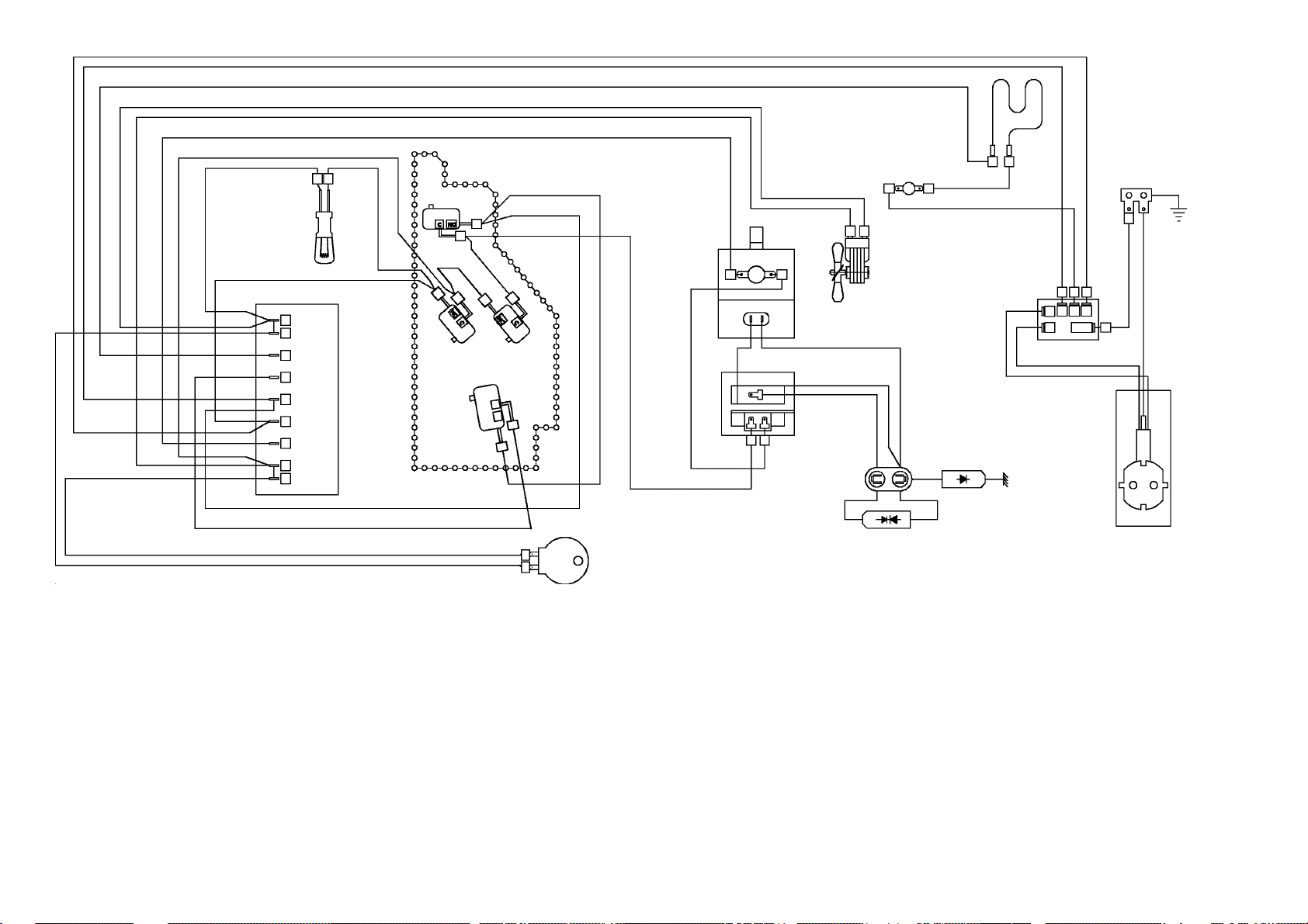
Page 3
BIANCO
NERO
PRI
NERO
BIANCO
ROSSO
BLU
MARRONE
BLU
THG
RG
BIANCO
BLU
OL
MARRONE
MARRONE
EC
F9
F8
SEC
F7
F3
F1
F2
3
F4
F5
F6
GRIGIO
GRIGIO
GRIGIO
ColoriColori
Colori
ColoriColori
ColoursColours
Colours
ColoursColours
FarbenFarben
Farben
FarbenFarben
ColeursColeurs
Coleurs
ColeursColeurs
ColoresColores
Colores
ColoresColores
Bianco White Weiß Blanc Blanco
Blu Blue Blau Bleu Azul
Giallo/Verde Yellow/Green Gelb/Grün Jaune/Vert Amarillo/Verde
Grigio Gray Grau Gris Gris
Marrone Brown Braun Marron Castano
Nero Black Schwarz Noir Negro
Ros so Red Rot Roug e Rojo
NERO
BIANCO
LOG
MON
DM
BLU
BLU
NERO
ROSSO
TH.MGT
HVT
MGT
HVC
FM
PDX
NF
GIALLO/VERDE
HVD
CA
SCHEDA TECNICA 97048
Page 4
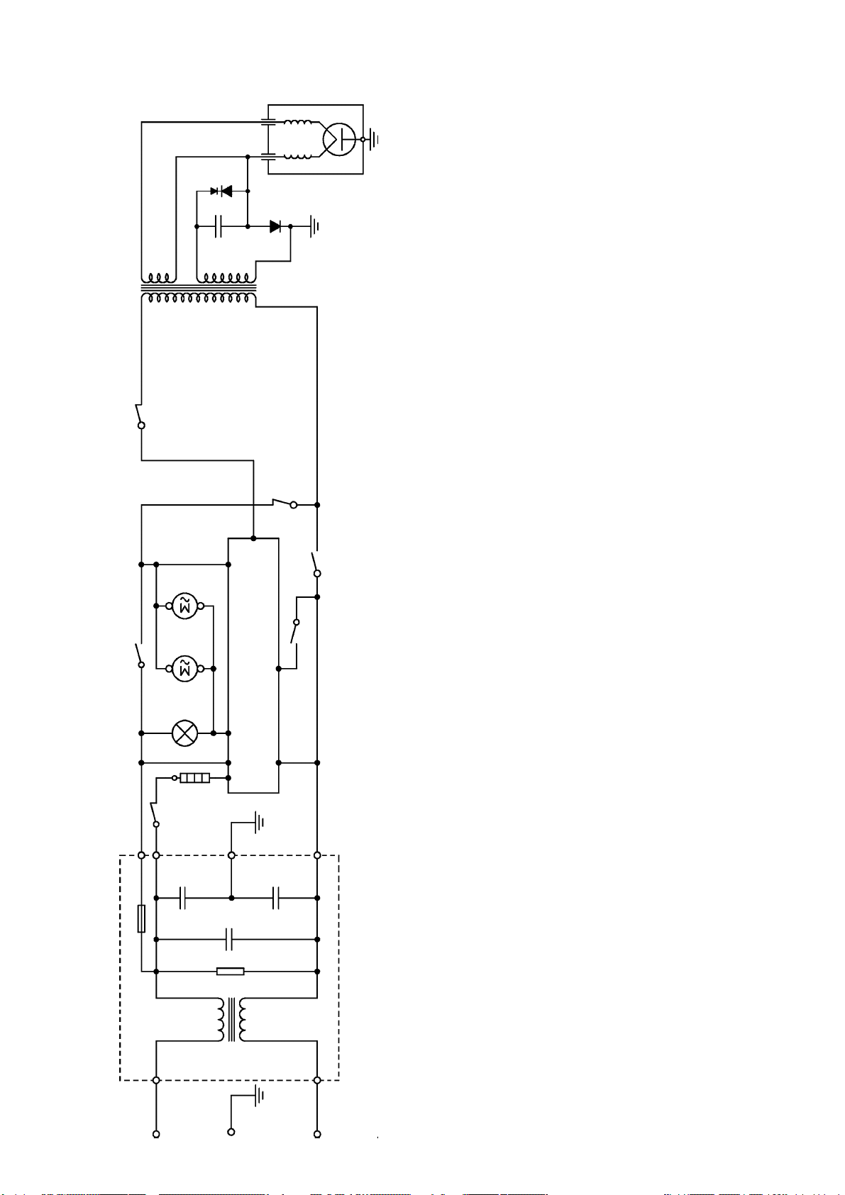
SCHEMA ELETTRICO / ELECTRIC DIAGRAM / SCHALTPLAN
SCHEMA ELECTRIQUE / ESQUEMA ELECTRICO
PDX
HVD
HVC
HVT
TH.MGT
MGT
SEC
THG
RG
DM
OL FM
F4
F5-F6
EC
F7 F2 F8-F9
MON
PRI
LOG
F1 F3
NF
Porta aperta / Door open / Tür auf / Porte ouverte / Puerta abierta
4
LEGENDA -LEGEND-ZEICHENERKLÄRUNG-LEGENDE-LEGENDA
CA Cavoalimentazione Power supply cable Netzkabel Cabled'alimentation Cabled'alimentasiòn
DM Motorepiatto rotante Turntable motor Drehteller-Motor Moteur plateau tournant Motor del plato giratorio
EC Controllo elettronico Electronic control Elektronisch Kontrolle Controle èlectronique Control electrònico
FM Ventilatore magnetron Magnetron ventilator Magnetron-Ventilator Ventilateur magnetron Ventilador magnetron
HVC Condensatore alta tensione High voltage capacitor Hochspannungskondensator Condensateur h.t. Condensador a.t.
HVD Diodo rettificatore a.t. High voltage retifier diode Hochspannungsdiode Diode h.t. Diodo a.t.
HVT Trasformatore alta tensione High voltage transformer Hochspannungstransformator Transformateur h.t. Transformador a.t
LOG Micronterruttore logico Logical microswitch Mikroschalter logisch Microrupteur logique Microinterruptor lògico
MGT Magnetron Magnetron Magnetron Magnetron Magnetron
MON Microinterruttore monitor Monitor microswitch Monitor Mikroschalter Microrupteur monitor Microinterruptor monitor
NF Filtro antidisturbo + Fusibile Antinoise filter + Fuse Netz-Filter + Schmelzsicherung Fitre+Fusible Filtro+Fusible
SCHEDA TECNICA 97048
OL Lampada forno Oven light Ofenbeleuchtung Lampe du four Lámpada horno
PRI Micronterruttore primario Primary microswitch Mikroschalter primär Microrupteur primaire Microinterruptor primario
PDX Diodo di protezione Protectiondiode Schutz diode DiodeProtection DiodeProtecciòn
RG Resistenza grill Grillheatingelement Grill-Heizkörper Elément chauffant gril Resistencia grill
SEC Microinterruttore secondario Secondary microswitch Mikroschalter sekundär Microrupteur secondaire Microinterruptor secundario
THG Termostatogrill Grillthermostat Grill-Thermostat Thermostat gril Termostatogrill
TH.MGT Protettore magnetron Magnetron protector Magnetron Temperaturbegrenzer Protecteur magnetron Protector magnetron
Page 5

BIANCO
NERO
PRI
NERO
BIANCO
ROSSO
BLU
MARRONE
BLU
THG
BIANCO
BLU
RG
SCHEMA ELETTRICO / ELECTRIC DIAGRAM / SCHALTPLAN
SCHEMA ELECTRIQUE / ESQUEMA ELECTRICO
5
SCHEDA TECNICA 97048
MARRONE
EC
GRIGIO
GRIGIO
GRIGIO
OL
F9
F8
F7
F3
F1
F2
F4
F5
F6
MARRONE
SEC
NERO
BIANCO
LOG
MON
DM
BLU
BLU
NERO
ROSSO
TH.MGT
HVT
MGT
HVC
FM
PDX
NF
GIALLO/VERDE
HVD
CA
ColoriColori
Colori
ColoriColori
ColoursColours
Colours
ColoursColours
FarbenFarben
Farben
FarbenFarben
ColeursColeurs
Coleurs
ColeursColeurs
ColoresColores
Colores
ColoresColores
Bianco White Weiß Blanc Blanco
Bl u Blue Blau Bleu Azul
Giallo/Verde Yellow/Green Gelb/Grün Jaune/Vert Amarillo/Verde
Grigio Gray Grau Gris Gris
Marrone Brown Braun Marron Castano
Nero B l ac k Schwarz Noir Negro
Ros so Red Rot Roug e Rojo
Page 6

PRECAUZIONI DA ADOTTARE CERCANDO GUASTI
A differenza di altre apparecchiature, il forno a microonde è un'unità ad alto voltaggio ed
amperaggio.Nonostante il suo
normale uso non presenti alcuna pericolosità, si deve usare estrema cautela durante le riparazioni :
- Toglietevi l' orologio operando in prossimità del magnetron.
- Attenzione al condensatore ad alto voltaggio, potrebbe rimanere carico per circa 30 secondi dopo che il
fornoha
cessato di funzionare.
E' opportuno scaricarlo ogni volta collegandone entrambi i poli con la massa per mezzo di un cavetto adeguatamente
isolato.
- I circuiti secondari del trasformatore presentano capacità di alto voltaggio ed alto amperaggio, è quindi
estremamente
pericoloso lavorare nelle vicinanze di questo componente quando il forno è alimentato.
- Non toccare nessun filo con le mani o con attrezzi non isolati durante il funzionamento.
- Non eseguire misure di tensione sul circuito ad alto voltaggio e sul filamento del magnetron.
- Accertarsi che la porta non sia allentata o mancante. Se le viti non sono perfettamente strette ci possono
essere
fughe di microonde.
- Accertarsi che tutte le connessioni elettriche non siano lasche prima di alimentare il forno.
- Accertarsi che non ci siano fughe di microonde seguendo l' apposita procedura.
- Non inserire alcun ogetto metalico attraverso le fessure della lampada o altre fessure del forno, perchè tali
oggetti
possono funzionare da antenna e causare fughe di microonde.
ATTENZIONE
RADIAZIONI A MICROONDE
- LE PERSONE NON DEVONO ESSERE ESPOSTE ALL'ENERGIA A MICROONDE CHE PUÒ ESSERE IRRADIATA DAL MAGNETRON O DA ALTRO DISPOSITIVO GENERATORE DI MICROONDE NEL
CASO DI UNA UTILIZZAZIONE O CONNESSIONE NON CORRETTA.
- TUTTE LE CONNESSIONI A MICROONDE DI ENTRATA E DI USCITA, LE GUIDE D'ONDA, LE
FLANGE E I GIUNTI DEVONO ESSERE SICURI.
- NON FAR FUNZIONARE IL GENERATORE SENZA UN CARICO PREVISTO PER ASSORBIRE
L'ENERGIA A MICROONDE.
- NON GUARDARE MAI ALL'INTERNO DI UNA GUIDA D'ONDA APERTA O DI UNA ANTENNA MENTRE IL GENERATORE È IN FUNZIONE.
- NON FAR FUNZIONARE IL FORNO, E NON PERMETTERE LA BENCHÈ MINIMA POSSIBILITÀ CHE
IL FORNO POSSA FUNZIONARE A PORTA APERTA
Eseguire i seguenti controlli di sicurezza su tutti i forni da riparare prima di attivare il magnetron o altro dispositivo generatore di microonde, ed eventualmente eseguire le necessarie riparazioni :
- Funzionamento del dispositivo di chiusura.
- Coretta chiusura della porta.
- Stato della chiusura della guarnizione e delle superfici di battuta.
- Danneggiamento od allentamento delle cerniere e degli agganci di chiusura.
- Segni evidenti di caduta od uso improprio.
Ogni componente difettoso o non correttamente tarato, posizionato nelle seguenti aree: chiusura, monitor,
guarnizione, porta, sistema di generazione e trasmissione delle microonde deve essere riparato,
sostituito,tarato.
ISTRUZIONI PER GLI INTERVENTI SUL MOTORE DEL PIATTO GIREVOLE
-Per accedere al motore tranciare le linguette che mantengono il coperchio
del motore ( vedi fig. A ).
- Dopo l'intervento rimontare tassativamente il coperchio con 2 viti
autofilettanti 4,2 x 9,5 senza punta.
6
Fig.A
SCHEDA TECNICA 97048
Page 7

MISURA DELLE MICROONDE DISPERSE
Ilcontrollodellemicroondedisperse deve essere effettuato dopo ogni riparazione ,
sostituzioneo regolazione delle parti, del sistema di aggancioechiusura porta, del modulo
interruttori,delmagnetron.
-mettere un recipiente con 250ccdi acqua al centro della
cavitàforno
-Accendereilforno alla massima potenza.
-Conunmisuratore di campo per microonde a 2.450MHZ,
controllareattentamenteledispersionimuovendo
lentamentelasondalungoil perimetro di battuta della
portalungolefughedelmobile.Perunacorretta
misurazioneattenersiscrupolosamentealleistruzioni d'uso
dellostrumento.
- La dispersione massima ammessa è di 5 mW cm a 5 cm.
2
Normalmentevieneassicuratauna dispersione più bassa
delminimoconsentito(<1mw/cm ).
2
MISURA DELLA POTENZA EMESSA DAL MAGNETRON.
NOTA: controllare il voltaggio di alimentazione,se dovesse essere inferiore a 230V
la potenza emessa dal magnetron risulterà più bassa.
-Riempirel'appositocontenitorecon1litrod'acquaatemperaturanormale.
-Mescolare col termometro erilevarela temperatura dell'acqua (T1).
-Posizionareilcontenitoresul vassoi o di vetro al centro del forno.
-Selezionarelapotenzamassimaefarfunzionareilfornoper63secondi.
-Mescolare di nuovo l'acquacoltermometroerilevare la temperatura (T2).
-L'innalzamentotermico deve essere circa 10 -12°C.
-Lapotenzaemessadalmagnetronpuòesserecalcolataconlaseguente
formula : P (W)=70 x(T2- T1 ).
Sela potenza è inferiore al nomimnale di oltre il15 %, sostituire il magnetron e verificare
lacapacitàdelcondensatoreA.T.
7
SCHEDA TECNICA 97048
Page 8

PROCEDURADICONTROLLOCOMPONENTI
ATTENZIONE : Eseguire i test di continuità con la spina disinserita e dopo aver scaricato il
condensatorecortocircuitando i terminali a massa conun cacciavite isolato
per 5000V. minimo
MAGNETRON
1) Scollegare il componente e collegare lo strumento ai terminali
del filamento : con il TESTER ohm x 1, la lettura deve risultare
inferiore a 1 ohm.
TRASFORMATORE
2) Scollegare tutte le connessioni del trasformatore con il
TESTER ohm x 1, le letture normali , a temperatura ambiente
dovrebbero essere :
2.1) Primario (vedi dati tecnici)
2.2) Filamento inferiore 1W
2.3) Secondario (vedi dati tecnici)
CONDENSATORE
ALTA TENSIONE 3) Scollegare tutte le connessioni del condensatore con il
TESTER ohm scala massima collegare lo strumento ai termi-
nali del condensatore : in primo momento si deve avere una
lettura come di continuità, che poi deve tornare a valore infinito.
3.1) La lettura tra ciascuno dei terminali e la cassa esterna deve
indicare un valore infinito.
Terminali
Cassa esterna
DIODO
ALTA TENSIONE
4 La continuità del diodo non si può misurare con un TESTER
mormale, in quanto presenta una caduta di tensione di 6.3V. Si
consiglia di collegare i terminali del diodo con una batteria ad 9 V
e una lampadina da 2,5 V collegata in serie.
.
- +
Batteria 9V
Lamp 2.5V
8
SCHEDA TECNICA 97048
Page 9

PRECAUTIONS TO BE TAKEN WHEN TROUBLESHOOTING
Unlike other appliances, microwave oven is a high voltage and high amperage unit. Even if you can use
it normally without any danger, you should be very careful during maintenance operations:
- Take off your watch when operating close to magnetron.
- Attention : the H.V. condenser could still be charged for about 30 seconds after the oven has been
switched off.
It is advisable to discharge capacitor each time by both poles through a suitably insulated cable.
-Secondary circuits of the transformer have ahigh voltage and a high amperage capacity,and therefore
it is extremely dangerous to work near this component when oven is plugged in.
- Never touch any wires with bare hands or with no-insulated tools when oven is operating.
- Do not measure voltage on high-voltage circuit or magnetron filament.
-Makesurethatdoorisnotlooseormissing.Ifscrewsarenotperfectlytightened,itmayleadtomicrowave
leaks.
- Make sure all electric connections are well tightened before turning on the oven.
- Make sure there is no microwave leakage following the proper procedure.
- Do not insert any metal object either through lamp crevice or any other oven crevice as such objects
could act as an antenna and provoke microwave leaks.
ATTENTION
When fuse cuts blows, always check primary, secondary, monitor and extra microswitches
efficiency, before turning the oven on. Should a microswitch be found defective, always change
allmicroswitches.
ATTENTION: MICROWAVE RADIATION
- PERSONNEL SHOULD NOT BE EXPOSED TO MICROWAVE ENERGY WHICH MAY
RADIATE FROM THE MAGNETRON OR OTHER MICROWAVE GENERATING DEVICE IF IT IS
IMPROPERLY USED OR CONNECTED.
- ALL INPUT AND OUTPUT MICROWAVE CONNECTIONS, WAVEGUIDES, FLANGES AND
GASKETS MUST BE SECURE.
-NEVER OPERATETHE DEVICEWITHOUTA MICROWAVEENERGY ABSORBINGLOAD, INSIDE
THE OVEN CAVITY.
- NEVER LOOK INTO AN OPEN WAVEGUIDE OR ANTENNA WHILE THE DEVICE IS WORKING.
- NEVER OPERATE OR ALLOW THE OVEN TO BE OPERATED WITH THE DOOR OPEN .
Make the following safety checks on all ovens to be serviced before activating the magnetron or other
microwave source, and make repairs as necessary :
-Interlock operation.
- Proper door closing.
- Seal and sealing surfaces state
- Damage or loosening of hinges and latches,
- Evidence of dropping or abuse.
Anydefectiveor misadjusted components in the interlock, monitor, door seal and microwavegeneration
and transmission systems shall be repaired, replaced, or adjusted .
INSTRUCTIONS FOR MAINTENANCE ON TURNTABLE MOTOR
-To reach the motor, cut the metal reeds that retain
Fig.A
the motor cover (see fig. ).
-After the operation set back the motor cover and
fix it with 2 self-threaded screws 4.2x9.5 with no sharp end.
9
SCHEDA TECNICA 97048
Page 10
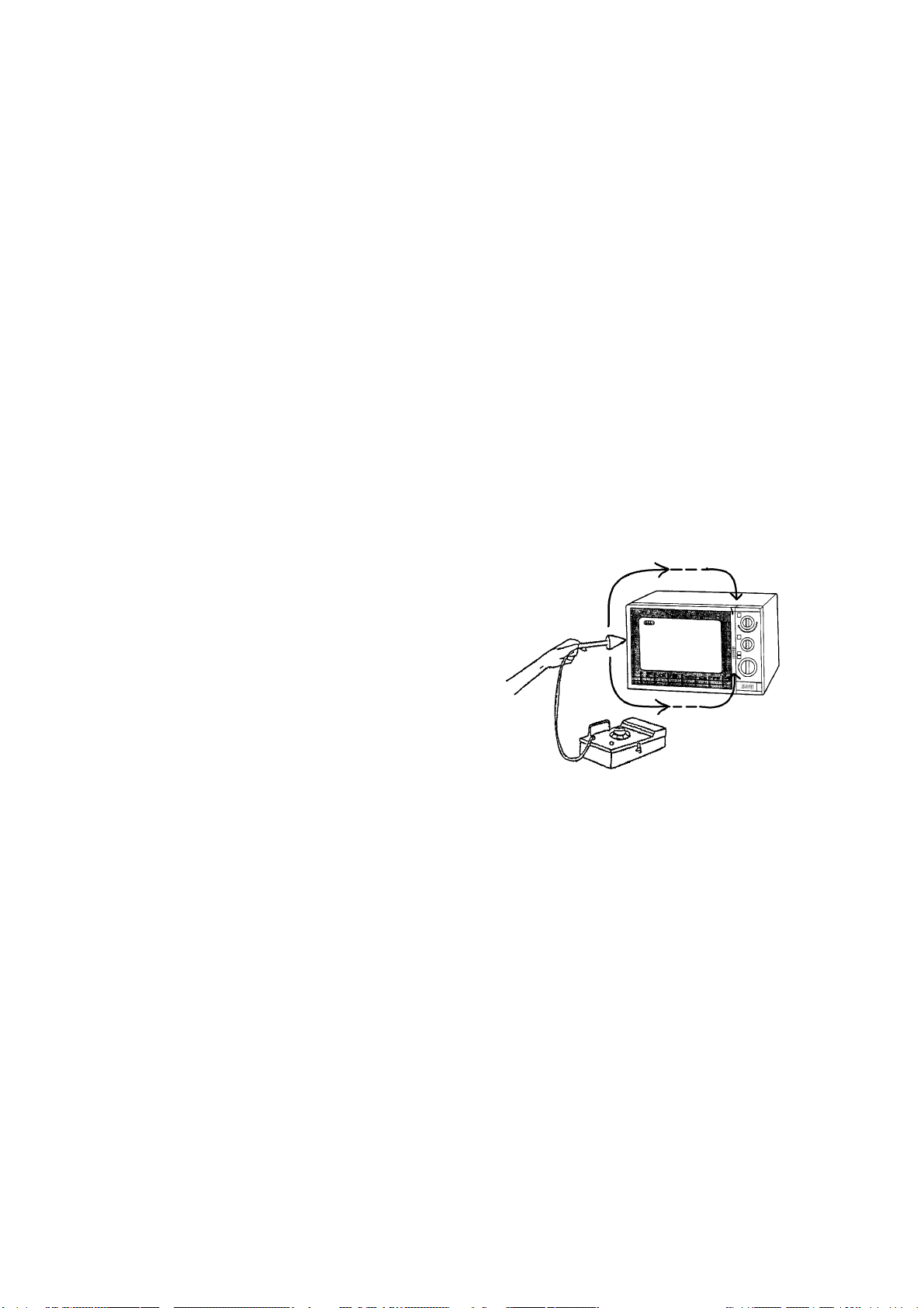
MICROWAVE LEAKAGE TESTMICROWAVE LEAKAGE TEST
MICROWAVE LEAKAGE TEST
MICROWAVE LEAKAGE TESTMICROWAVE LEAKAGE TEST
This test has to be done after every manteinance operation regarding the door and the
whole closure system, microswitches and magnetron.
Testequipment:
- 600 ml beaker
- Microwave surveymeter
Testprocedure:
- Place250 ml water in a beaker and place it in the centre of the oven
- Turnonoven,settimerfor 5minutesatfullpower
- Holdthe probe of the microwavesurveymeterperpendicularto the door edge of the
ovenandscanitveryslowly.
Testthefollowingareas:
- Doorand controlpanel
- All ventilationopenings
- Alllockseams
- Weldatborrom
- Bottomplate
Operations:
- Openthe door to thepositionatwhich the oven is justabouttoturn off, scan the door
perimeter.
- Thedistancebetween door and probe must be at
least 5 cm
- Maximumallowableleakage is 4 mW /cm
2
MAGNETRON POWER TEST
Thestandard test loadisonelitre (1000 ml)waterwithan initial temperatureof15- 24 °C(58- 75
°F)in a1000mlbeaker.Donot useanyotherloadordishotherwise testresultwillvaryfromstandard.
Testprocedure:
- Measureand adjust thevoltageof the ACpowersupplyto its correctvalue.
Bearinmindthattestresultisinfluencedbythevoltagesupplyvalue.
Toolow ortoohighvoltagewill notdeterminean accuratemeasurement.
- Placebeakercontainingexacly 1000 ml water at 15 - 24°C in the centre of the oven.
Usean accuratethermometerto readtheinitial watertemperatureT1.
- Settheappliancefor63secondsatfull power.
- Atthe end of this period, stir the water quicklyandreadthewaterfinaltemperature T2.
Thedifference betweenthefinal temperatureT2and theinitialtemperature T1isthe
temperaturerise.
Result:
- Themicrowavepoweroftheoven canbedeterminedbythe followingformula:
P (W) = 70 x (T2 - T1)
If power is more than 15% off the nominal power of the M.W., then verify High Voltage
Capacitor and eventually change magnetron.
10
SCHEDA TECNICA 97048
Page 11

COMPONENTS TEST PROCEDURE
MAGNETRON 1. Chek resistance: Normal reading:
Across the filament terminals Less than 1 Ohm
of the magnetron with an Ohmmeter on R x 1 scale.
2. Chek resistance: Normal reading:
between each filamet terminals infinite Ohm
of the magnetron and the chassis
ground with an ohm-meter set on
highest scale
HIGH VOLTAGE 1. Measurement the resistance: Normal reading:
TRANSFORMER with ohm-meter onRx1scale.
a) Primary winding: - appoximately 1.24 Ohm
b) Filament winding: - less than 1 Ohm
c) Secondary winding: - appoximately 87 Ohm
2. Measure the resistance: Normal reading
with an ohm-meter on highest scale
a) primary winding to ground - infinitive Ohm
b) Filament winding to ground - infinitive Ohm
HIGH-VOLTAGE 1.Measuretheresistance: Normalreading:
CAPACITOR Across the terminals of the Momentarilyindicatesseveral
capacitorwith an ohm-meteron Ohm,andthen gradually returns
highest scale. to infinite Ohm.
Abnormal reading:
indicates continuity or infinite
Ohmfromthebeginning.
Terminals
External housing
CAUTION: discharge high voltage capacitor before cheking parts of high voltage circuit.
DIODE
1. Checkdiode:
Across the terminals with a 9V
battery and 2.5V lamp circuit.
- +
Lamp 2.5V
11
Normal reading:
Lamp is ON or OFF depending
onpolarityofvoltage.
Abnormal reading:
Lamp is too bright : short circuit
Lamp is never ON : open circuit
SCHEDA TECNICA 97048
 Loading...