

Page 1
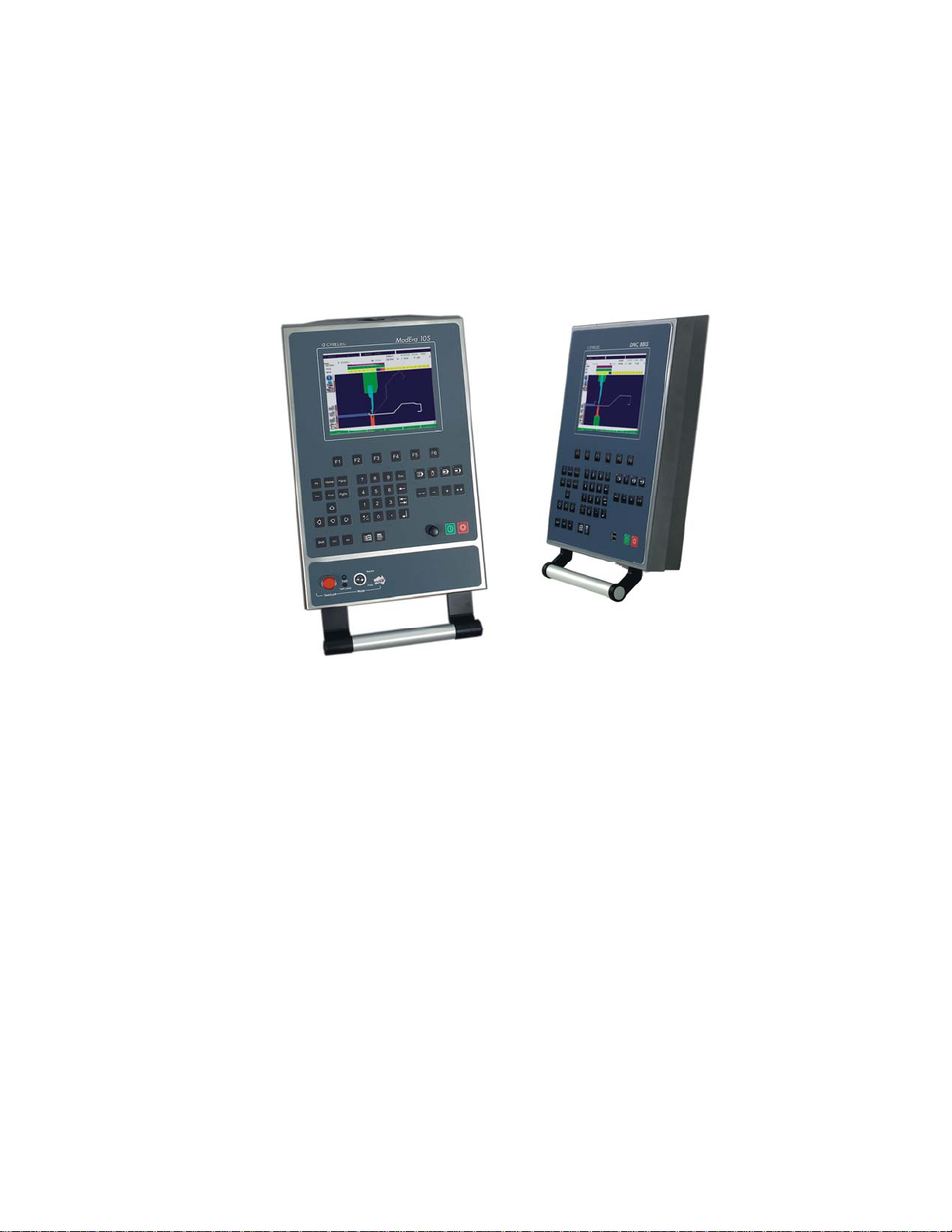
ModEva/DNC880S
PC 1200 2D
2D Reference Manual
CYBELEC SA Tel. ++ 41 24 447 02 00
RUE DES UTTINS 27 Fax ++ 41 24 447 02 01
CH - 1400 YVERDON-LES-BAINS E-Mail: info@cybelec.ch
SWITZERLAND
V-DOC-MODEVA-EN
Page 2

Page 3

Page 4

Page 5

August 3, 2006 V. 1.3
TABLE OF CONTENTS
INTRODUCTION..............................................................................................................................5
About this Manual 5
Licence Agreement and Copyright 5
CONVENTIONS...............................................................................................................................7
DEFINITIONS...................................................................................................................................11
ABS .....................................................................................................................................11
REL 11
Active Peripherals ........................................................ .......................................................12
Active Peripherals Machine 12
Active Peripheral Products 13
Active Peripheral Punches / Dies 13
Admissible Force applied to the Dies.. ................................................................................13
Alphanumeric Fields............................................................................................................15
Angle Corrections................................................................................................................16
General Remarks 16
Direct Corrections 16
Angular Corrections 17
Corrections by Thickness Measurement 17
Measuring at the TDC 18
Measuring at the PP 20
Independent Thickness Correction Y1-Y2 22
Corrections: Sensitivity BDC 22
Auxiliary Functions ..............................................................................................................23
Backgauge Retraction.........................................................................................................23
Bend ....................................................................................................................................23
At the bottom of the Die 23
Final 23
Intermediate 23
Sequence without Bend 24
Bend Counter ......................................................................................................................24
Bending Force.....................................................................................................................24
Bending Order.....................................................................................................................25
Automatic Bending Order 25
Modifying the Bending Order 25
Unbend Mode 27
Bending Speed....................................................................................................................29
BG (Backgauge) or STOP...................................................................................................29
Bottoming ............................................................................................................................30
Corrections (Table)..............................................................................................................31
Crowning .............................................................................................................................32
MODEVAREF2D_EN.DOC TABLE OF CONTENTS PAGE 1
Page 6

Data Backup ... ................................................................................... ................................. 32
Data Transfer................. .................................................................................. ................... 33
Date and Hour .................................................................................................................... 35
Decentered Punches & Backgauge Correction.................................................................. 36
Depth Collision authorized.................................................................................................. 36
Drawing............................................................................................................................... 37
Dwell Time.......................................................................................................................... 38
Erase / Delete............................................................................. ........................................ 38
Erasing Memories...............................................................................................................39
Free Memory ...................................................................................................................... 39
Gauge Clearance ..................................................... .......................................................... 40
Ideal Curve (CR)................................................................................................................. 41
PRODUCT NUM Page 41
Indexing Axes ..................................................................................................................... 46
Inserting a Sequence.................................................................. ........................................ 46
Internal Radius.................................................................................................................... 47
Keyboard ............................................................................................................................48
L. Bending........................................................................................................................... 48
Language............................................................................................................................ 49
Leaving the Software.......................................................................................................... 49
Leg...................................................................................................................................... 50
Length................................................................................................................................. 51
Low Speed Distance ...................................................................................................... 51
Machine Parameters .......................................................................................................... 51
Maintenance ....................................................................................................................... 52
Manual Adjustment of the Backgauge................................................................................ 52
Modifying the Origin of the Axes...... ................................................................................... 53
Parametric product ............................................................................... .............................. 55
Activation of the function 55
Create a parametric product 55
Working with a parametric product 59
Product Groups................................................................................................................... 60
Definitions 60
Working example in the PRODUCTS GROUP page 61
Product information ............................................................................................................ 62
See an Informtion 63
Creating an Information (text only) 63
Creating an Information (text and images) 63
Product Management ......................................................................................................... 66
Programming a Profile........................................................................................................ 67
Programming on Bend Num............................................................................................... 67
Programming while working ............................................................................................... 68
Q.Needed. ___ Done.___................................................................................................... 69
Reference YR cor. .................................................................................... .......................... 69
Screen Capture................................................................................................................... 70
Black and white, colour 70
Screen printing 71
Searching for Products according to Criteria ..................................................................... 73
Memorization date 74
Section................................................................................................................................ 75
Sigma.................................................................................................................................. 75
Simulation criteria ............................................................................................................... 76
SP (Switch Point)................................................................................................................ 79
Special bends ..................................................................................................................... 80
Preliminary / Final bend 80
Start Axes/AF.. .................................................................................................................... 85
PAGE 2 2D REFERENCE MANUAL MODEVA/DNC 880S
Page 7

TDC (Top Dead Centre)......................................................................................................86
Tolerance.............................................................................................................................87
Too short segment authorized ............................................................................................88
Tools....................................................................................................................................88
Programming punches 89
Programming dies 91
Modifying a tool 93
Tool positions 93
Punch list / Die list 93
Unfolded Length..................................................................................................................94
DIN 95
REAL 95
Correction coefficient of calculation DIN 6935 95
INDEX ..............................................................................................................................................97
TABLE OF CONTENTS PAGE 3
Page 8

This page has been left blank intentionally.
PAGE 4 2D REFERENCE MANUAL MODEVA/DNC 880S
Page 9

INTRODUCTION
ABOUT THIS MANUAL
This document has been conceived to try and answer particular questions
after having acquired the basis for using the ModEva/DNC 880S software.
It is complementary to the User guide which informs you about the basic
procedures to be followed for using this software.
A supplement called 3D Reference manual is supplied with the ModEva
software in 3D version.
This manual is organized like a dictionary, that its elements are classed in
alphabetical order.
If a subject is dealt with in another chapter than the one in which you are
looking for information, you will find a reference to the new subject.
An index situated at the end of the manual completes and facilitates the
search for information. Do not hesitate to use it.
Some functionalities treated in this manual are not available on
DNC 880S.
LICENCE AGREEMENT AND COPYRIGHT
This manual is subject to the licence and copyright agreem ent to be found at
the beginning of this manual.
INTRODUCTION PAGE 5
Page 10

This page has been left blank intentionally.
PAGE 6 2D REFERENCE MANUAL MODEVA/DNC 880S
Page 11
CONVENTIONS
As a general rule, in this manual, we will not repeat how to validate a field,
select a tool, call a page or any other basic manipulations.
These are described by means of examples in the User guide of the numerical
control or the relevant software.
In order to ensure a better readability of the reproduced screens, these ones
have been converted in black and white.
Possibly, certain screens illustrated in this manual may not correspond
exactly to your software, this can result from the configurati on of your
software (number of options, axes, etc.) or from the used software version
(DOS or Windows).
Typographical conventions
Arial bold Quotations of text as seen on the screen.
Arial bold italic Used to indicate the name of a DNC input or
Italic Reference to a written element , a paragraph or
output.
a manual.
For example: See Typographical conventions.
Indicates a double pressure on the key.
General conventions for this manual
It is accepted that:
Mouse means a mouse for a PC
or trackball / tracksensor for a DNC.
Click press the left mouse button.
Click right press the right mouse button.
Click left/right press simultaneously the left and right mouse
buttons.
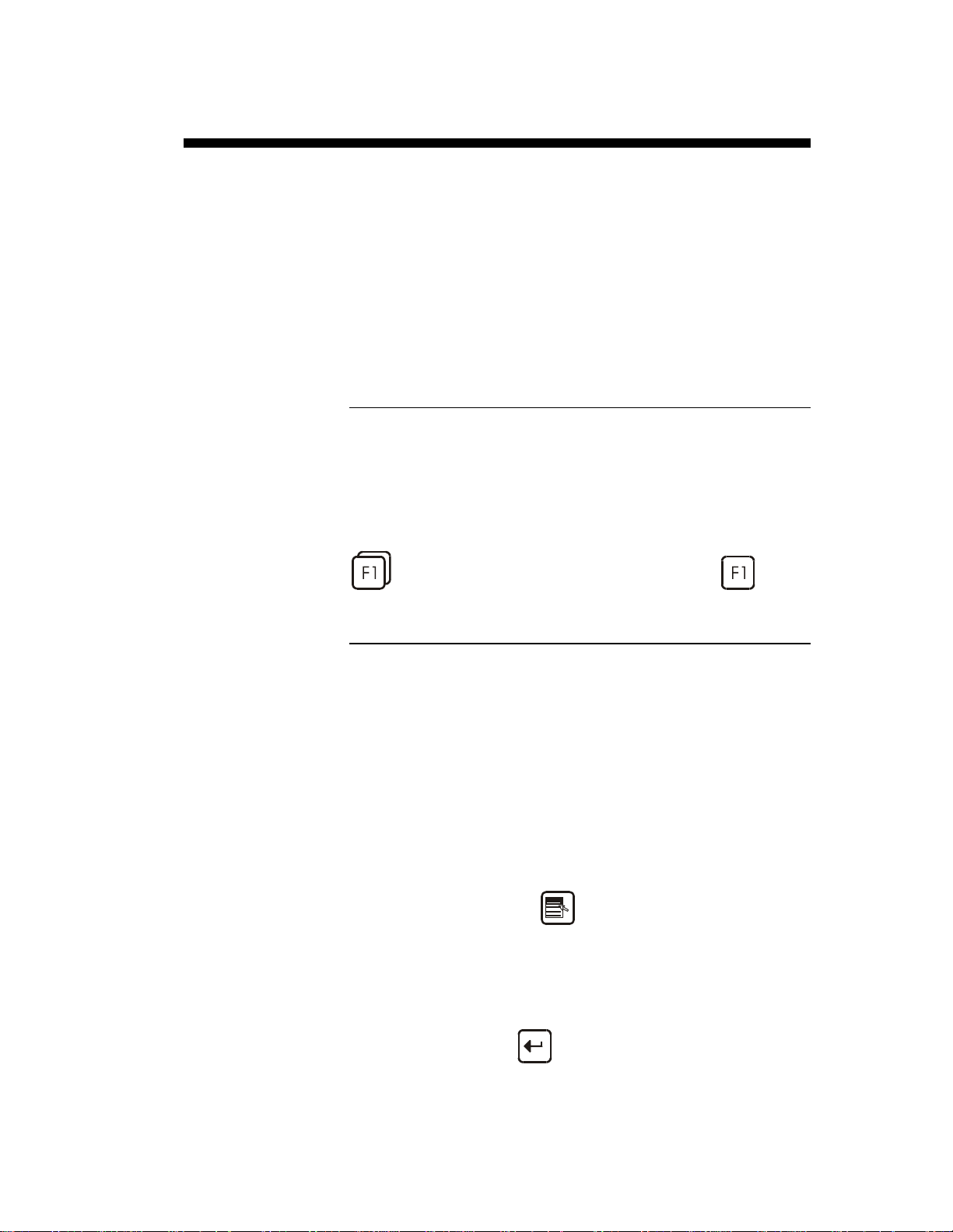
Round robin lists or multiple choice fields:
They are violet coloured and signify that several
options are available.
The choice of the contents is made by pressing
the
A window appears displaying the list of the
available choices for this field.
To validate the choice:
- type the number indicated next to the choice,
or
- place the cursor on the choice and press the
key.
key.
CONVENTIONS PAGE 7
Page 12
It is possible, without displaying the choice
window, to make appear one after the other the
Reach the BEND 2D
page
choices by pressing the
To validate, leave the field.
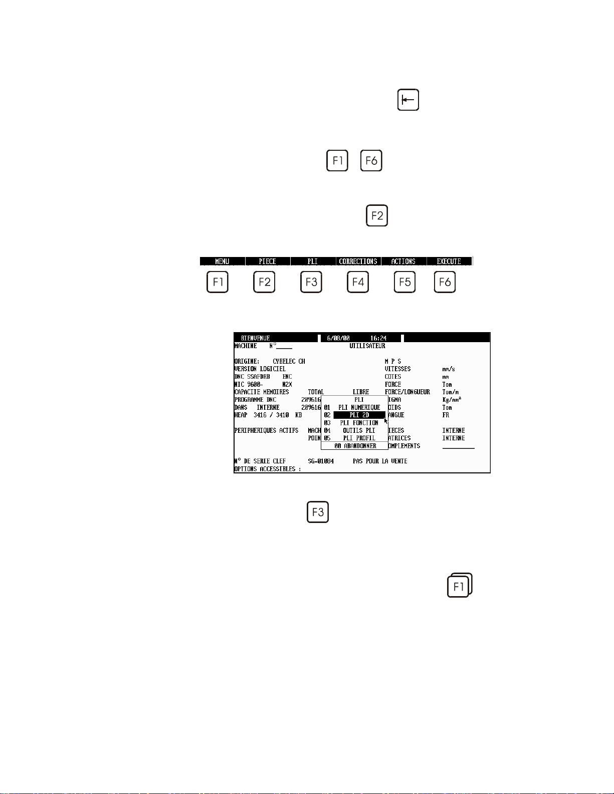
Function keys
Each time you are asked to press a function
key
appears.
Generally, the name of the function key will be
used. For example: press PRODUCT
designates the
to , the appropriated menu
key.
key.
Example when you want to reach the
BEND 2D page, press the function key BEND
, then sélect BEND 2D or simply type 02
(or the number indicated next to the choice).
Rapid validation To facilitate the operator's work, the DNC
memorizes the last choice made in a menu.
To validate faster an option of a menu, just
double press on a function key (e.g.:
directly validate the last select ed page.
PAGE 8 2D REFERENCE MANUAL MODEVA/DNC 880S
), to
Page 13

Software conventions, Windows version
In basic configuration, the Windows version uses the following colours:
Black Designates fixed information, designates fields
etc.
or
fields accessible by the cursor which can be
modified by the user.
Blue Used for titles and headnotes.
Bluish-grey Variable information. Not accessible by the
cursor.
Green Scrolling fields. Accessible by the user for
choosing between several predefined options
(see Scrolling lists above).
CONVENTIONS PAGE 9
Page 14

This page has been left blank intentionally.
PAGE 10 2D REFERENCE MANUAL MODEVA/DNC 880S
Page 15
DEFINITIONS
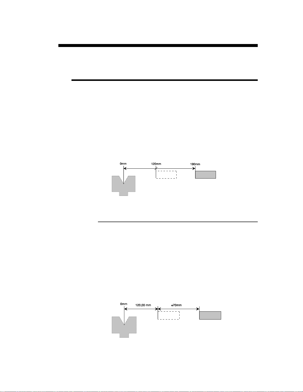
ABS
Page: BEND NUMERICAL
This round robin list is placed next to the name of the axis of the X stop.
Two choices: ABS and REL.
ABS indicates that the X axis functions in absolute mode.
This means that the destination of the axis is an absolute distance m easured
from the die V.
Absolute mode is selected by default.
See REL below.
Example: MEM POS
X ABS 190.00 120.00
REL
REL indicates that the X axis functions in relative mode.
This means that the displacement program med is made departing from the
actual stop position.
Generally a negative value is programmed.
The relative mode is often used with the cycle repetition (CY 2 at 99).
For example with a punching tool, you wish to make 5 holes equidistant of
30.00mm. The first sequence must be in absolute mode (location of the first
hole. The second sequence will be programmed in relative mode
(X REL 30.00) with a cycle repeti tion equal to 4 (CY 4).
Example: MEM POS
X REL 70.00 120.00
DEFINITIONS PAGE 11
Page 16

Remark: It is not possible to use the relative mode on the first sequence.
ACTIVE PERIPHERALS
Page: WELCOME
Aim:
This function allows to choose the peripheral containing the required
information and this separately for the machine parameters, the products, the
tools the CAD files and the complementary files on the product information
page.
It offers a multitude of combinations especially appreciated on a PC work
station. Effectively using these choices, the operator could easily manage
several machines.
The comprehension of this notion is important, as its flex ibility allows a large
diversity of choice.
Definition:
The active peripheral is the peripheral in which the software is going to read,
search, save or delete data. The active peripherals are designated on the
WELCOME page.
On certain pages, another peripheral can be temporarily selected for an
operation (for ex. PRODUCT LIST, PROGRAMMING PUNCHES /
DIES, TRANSFER).
If such is the case, an error is generated when changing mode
(AUTO, SEMI-AUTO) and the message DEPL. X REL.
IMPOSSIBLE is displayed in the interactive field.
Active Peripherals Machine
When you change the peripheral in the MACHINE field, automatically
PRODUCTS, PUNCHES and DIES are redirected on to the same
peripheral.
To change them independently one from the other, you must simply modify
them afterwards.
The CAD FILES and COMPLIMENT peripherals are not modified
automatically, as they are generally situated on a network and are often the
object of a “specific classification” in one or several directories.
By modifying in this way the MACHINE peripheral, the environment of the
software “ becomes” that of another machine. It is thus easy to simulate
products for different configurations of pressbrakes.
Also, more and more you will find diskettes containing examples of special
products (supplied by CYBELEC or by the machine manufacturer) for which
the realization needs a specia l (Tools for example). With th is possibility you
can thus easily visualize these demonstrat ions with all the machine context in
which they were created.
On a numerical control, it is evidently only possible to work with a machine
when the MACHINE field is switched to INTERNAL.
If another peripheral is used to visualize a demonstration product for
example, it will however still be possible to switch the DNC to semi-auto or
auto mode.
PAGE 12 2D REFERENCE MANUAL MODEVA/DNC 880S
Page 17
However the massage ENC NOT CONNECTED will appear and it will not
be possible to work with the machine.
To reactivate the INTERNAL machine peripheral, you must:
Select MACHINE INTERNAL.
Initialize the ENC by pressing INIT ENC, Action menu.
Active Peripheral Products
Selects the default peripheral in which the operations of searching, saving
and deleting of products is effectuated.
Active Peripheral Punches / Dies
Selects the default peripheral in which the operations of searching, saving
and deleting punches and dies is effectuated.
Evidently the tools specified in the current product must be available in the
addressed peripheral, without which the software will give an error message.
ADMISSIBLE FORCE APPLIED TO THE DIES
Page: PROGRAMMING OF DIES
The maximum admissible force is defined when programming the tools. In
reality however, the admissible maximum force varies depending on the
bending angle (and, of course, on the other customary parameters).
The die programming page contains two pairs of fields which make it
possible to adapt the safety parameters.
The fifth field enables the user to test the result.
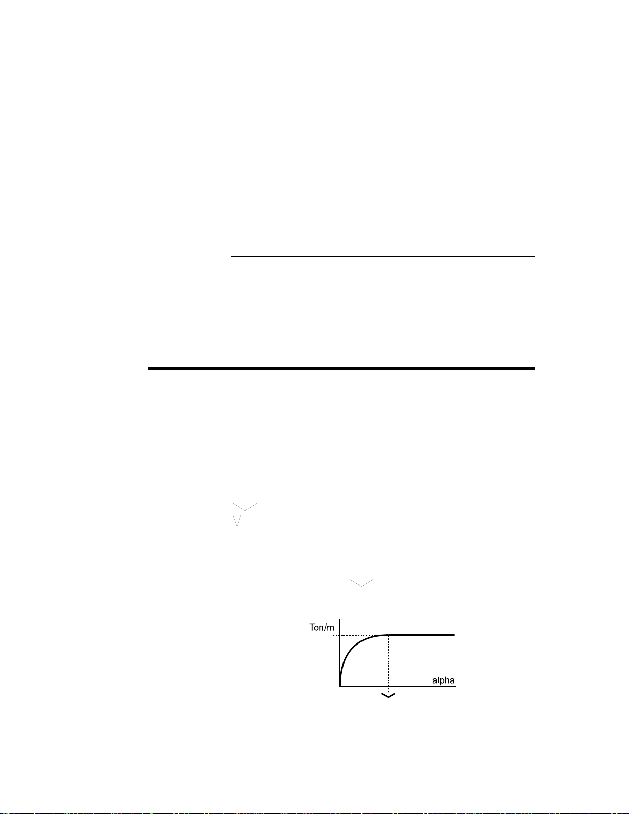
When only the first Ton/m field is programmed, this means that the pressure
limit is constant and not depending on the angle.
__._° -> max 200.0 Ton/m
__._° -> max ___._ Ton/m
Test 90.0° = 200.0 Ton/m
The Test field indicates the maximum admissible force for the programmed
angle.
When the fields "open angle"
programmed, the calculation of the admissible force is limited according to
the diagram shown below.
and Ton/m on the same line have been
DEFINITIONS PAGE 13
Page 18
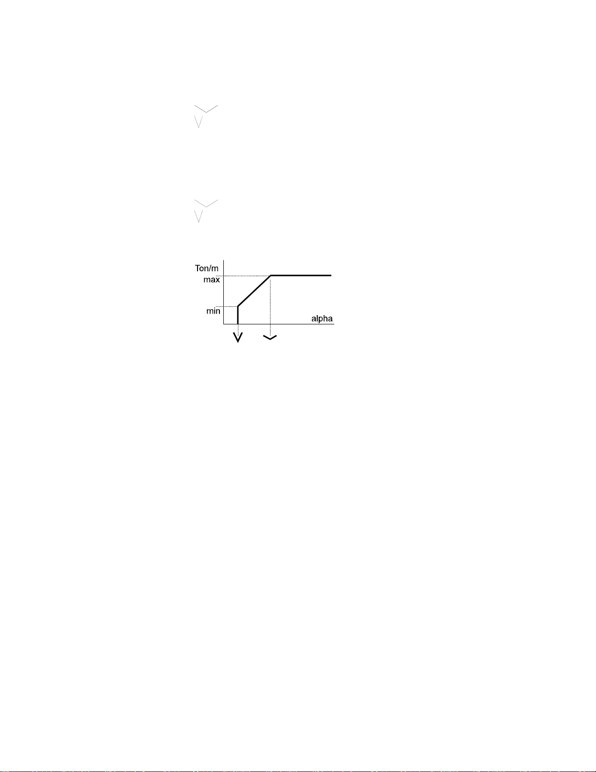
If there is no specific indication given by the manufacturer, you enter the
maximum admissible force already known, and an "open angle" of 90°
(as below).
90.0° -> max 200.0 Ton/m
__._° -> max ___._ Ton/m
Test 60.0° = 115.5 Ton/m
When the 4 fields have been programmed, the calculation of the admissible
force is limited according to the diagram bel ow. The choice between the
above method and the method explained in this paragraph depends on the
known data and the decision of the person who enters the die data.
90.0° -> max 200.0 Ton/m
30.0° -> max 45.0 Ton/m
Test 60.0° = 122.5 Ton/m
PAGE 14 2D REFERENCE MANUAL MODEVA/DNC 880S
Page 19
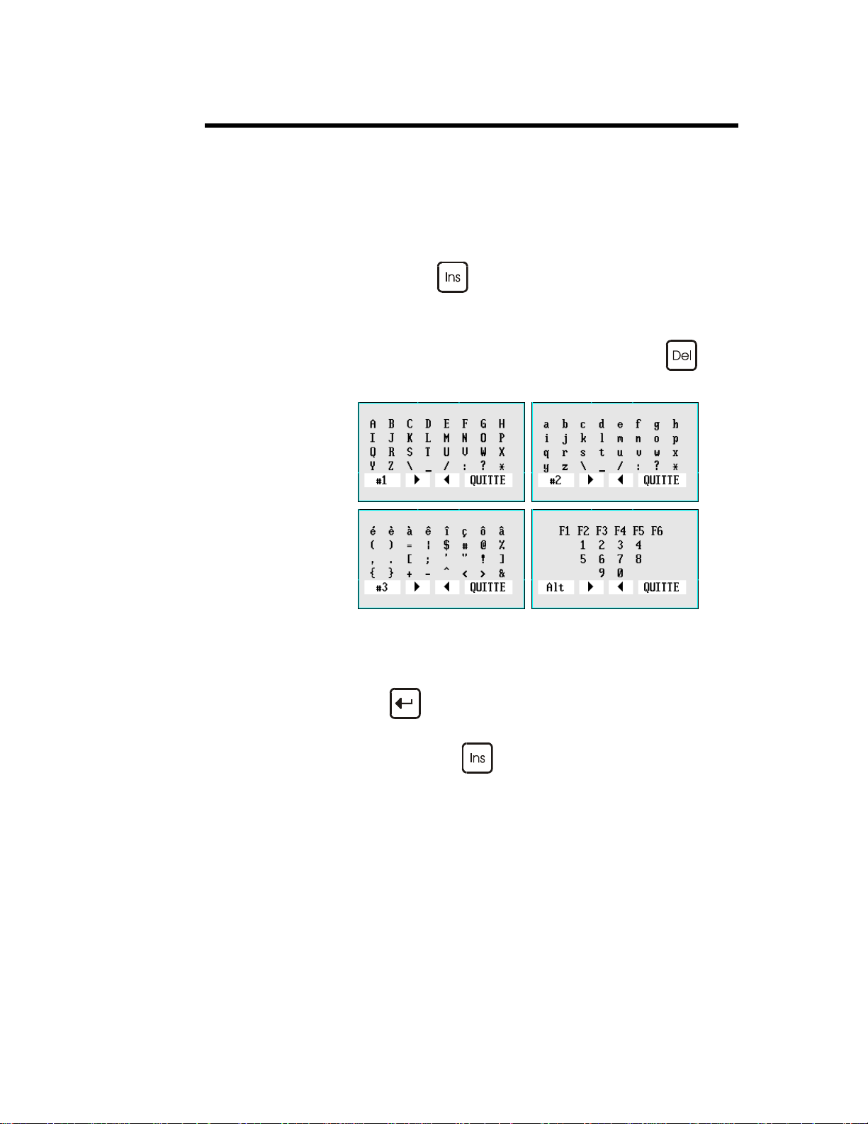
ALPHANUMERIC FIELDS
Certain fields (DRAWING, PUNCH, DIE etc.) can contain alphanumeric
characters.
To program the alphanumeric fields on the numerical controls, you must use
the "soft" alphanumeric keyboard.
To call the "soft” alphanumeric keyboard in the software , position the cursor
on the alphanumeric field (if the field is only numeric the keyboard will not
appear) and press the
4 tables of characters are available (#1, #2, #3 and Alt).
To change the "table":
Point to the field bo ttom left #1, #2, #3 or Alt and press
or click left in this field.
To enter the characters in to the alphanumeric field:
Select the character.
key.
Press
Repeat the operation for the other characters.
To leave, press the
DEFINITIONS PAGE 15
or click left.
key again.
Page 20
ANGLE CORRECTIONS
Pages: CORRECTIONS
GENERAL REMARKS
The sheet metals used in the workshops have hardly ever their nominal
thickness. The real thickness commonly varies ±10% from the nominal
value. Also the variation is not constant across the whole length of the sheet.
The thickness on the left side can be different to the thickness on the right
side (sheets with a trapezoidal section). The software allows to correct this
type of error by dissociating the correction of one extremity from that of the
other extremity of the bend.
The bending depth calculations (as well as those for elongation, pressure and
crowning) are based on the nominal thickness (that which is programmed in
the THICKNESS field).
In this Angle corrections chapter we will deal with 3 types of correction:
Direct corrections
Angular corrections
Corrections by measuring the sheet thickness.
Depending on the field in which it is entered, a correction can act on:
The relevant bend (uniquely)
All the bends (with the same angle) situated on the sam e section
(same profile)
All the bends (with the same angle) of the product (also on distinct
sections)
DIRECT CORRECTIONS
To use direct corrections, the DNC must be in programming or semiautomatic mode and you simply enter a value in to the required field on the
first table of the page. The number of the current bend is located at the top of
the screen.
If the correction concerns the two sides of the beam, the sam e value for Y1
and Y2 must be entered.
It is also possible to correct the other axes, the PP, the bending force and the
crowning according to the same principles.
PAGE 16 2D REFERENCE MANUAL MODEVA/DNC 880S
Page 21
Direct corrections are additioned. This means that if there is a global
correction for the product and a correction for a given bend is programmed,
the final correction for this bend will be the sum of the two corrections.
ANGULAR CORRECTIONS
After having made a bend, the operator measures the angle obtained. The
measured angular value is entered in to the ANGLE field. The DNC
automatically calculates the correction to obtain the angle originally
programmed. If after making the corrected bend, the angle is still not correct,
simply enter the new measured angle value. In certain cases this operation
may have to be repeated 2 or 3 times.
Attention, you must not intervene in the direct corrections table
simultaneously with the angular corrections.
As for the direct corrections the corrections can be attributed to:
BEND Corrects only the current bend.
SECTION _ Corrects all the angles of the specified section
which have the same programmed value and the
same tools.
PRODUCT Corrects all the angles of the product which
have the same programmed value and the same
tools.
The DNC must be in programming or semi-automatic mode.
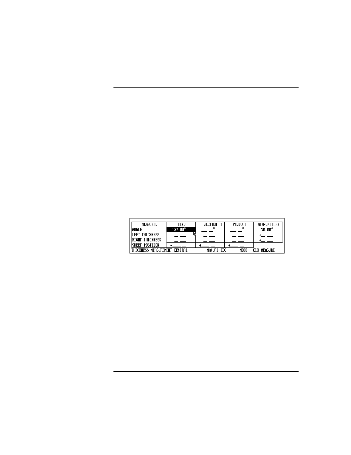
Program the THICKNESS MEASUREMENT field in the following
manner:
THICKNESS MEASUREMENT CENTRAL NONE MODE OLD MEASURE
Measure the angle obtained.
Introduce the measured value in to the ANGLE field under one of the
columns BEND, SECTION or PRODUCT.
Test the result and redo if necessary.
See also the machine para meter COMPENSATION ELASTIC RETURN
on the MATERIAL page. This parameter allows to correct in p ermanence an
angle in a given plane.
CORRECTIONS BY THICKNESS MEASUREMENT
Correction by thickness measurement can be realized in several ways, but the
principle remains identical. A system (or the operator) furnishes the DNC
with the real measurement of the material. With these parameters, the DNC
calculates the necessary correction.
DEFINITIONS PAGE 17
Page 22

The two main methods are:
Measuring at the TDC (Top dead center)
Measuring at the PP (Pinch point).
Measuring at the TDC The principle is that the measurement is made
and entered in to the DNC while the machine is
at the TDC.
The measurement is entered either conventionally using the keyboard, or by a RS232 link
using an adequate instrument of measure, or
otherwise by a system integrated at the stop.
Measuring at the PP In this case the measurement is made at the PP.
Three possibilities are offere d.
- Measurement by the beam.
- Measurement by the beam with die
displacement.
- Measurement of the real PP by an external
system.
As for the direct and angular corrections, it is possible to affect the correction
to the current bend, to the section or to the whole product.
Also, with the correction in function of the measurement of the thickness, it
is possible to differentiate the correction for each extremity of the bend. The
choice is made using the round robin list CENTRAL or EXTREMITIES.
(See further on in this chapter for the use of this possibility).
Remarks: For technical reasons, you can only pass to programming mode
during working (DNC in automatic mode and programming) if
NO THICKNESS MEASUREMENT has been selected.
For technical reasons, the fields POS. SHEET and
THICKNESS MEASUREMENT can no longer be modified
in semi-automatic mode.
Measuring at the TDC
As described in the introduction to this chapter, the measurement is made
when the beam is at the TDC.
Only the introduction of the measurement by the operator , such as the
"standard" DNC software will allow, will be described in this paragraph.
The DNC must be in programming or semi-automatic mode.
Proceed in the following way:
Program the THICKNESS MEAS URE MENT field in the following
way:
THICKNESS MEASUREMENT CENTRAL TDC MANUAL MODE BY BEND
PAGE 18 2D REFERENCE MANUAL MODEVA/DNC 880S
Page 23

Measure the thickness very precisely (using a micrometer).
Enter the measured value in to the LEFT THICKNESS field of the
PRODUCT, SECTION or BEND column depending on your needs.
By only programming the LEFT THICKNESS field, the software
assumes that the measurement is central.
Leave the field.
Bend.
If the introduction is made in the
PRODUCT column:
- The measurement made by the operator on whatever bend will remain
valid until the next measurement.
- The real thickness obtained is saved in association with the product.
- It is considered that the real thickn ess is the same for all the bends.
- At each new measurement, all the bends are re-corrected.
- If no measurement is made, the correction is made according to the
last measurement saved.
SECTION
- The measurement made by the operator on whatever bend of the
section will remain valid until the next measurement..
- The real thickness obtained is saved in associati on with the section to
which belongs the bend on which it was made. It is valid for all the
successive bends belonging to the same section.
- If a new measurement is made, all the bends of the relevant section
are re-corrected.
- If no measurement is made, the correction is made according to a
possible former measurement saved in association with that section.
Remark: This means that if any values are present in the SECTION
column, they will be taken in to account and the values in the
PRODUCT column will be ignored. If there are no values in
the SECTION column, the values in the PRODUCT column,
if they exist will be taken in to account.
BEND
- The measurement made by the operator on whatever bend is only
valid for that bend. It will also be memorized.
- If no measurement is made, the correction is made according to a
possible old measure memorized in association with that bend.
Remark: If any values are present in the BEND column, they will be
taken in to account and the values in the SECTION and
PRODUCT columns will be ignored. If there are no values in
the BEND column, the values in the SECTION column, if
they exist will be taken in to account. If only PRODUCT
column contains any values, then it is these that will be taken
into account.
DEFINITIONS PAGE 19
Page 24

Measuring at the PP
Only the measurement at the PP with the beam will be described in this
chapter.
Principle:
The beam makes its usual approach (in semi-auto or autom atic). When it
reaches just before th e th eoretical PP, the DNC reduc e s th e syste m pressure
and "lands" freely on the sheet. The DNC detects the stopping of the beam
and in this way allows the measurement of the sheet thickness.
It is evident that in this phase the sheet must not flex under the influence of
the beam, otherwise the measurement will be falsified. The way in which this
option functions will depend directly on the machine hydraulics, the speed
when arriving on the sheet and the minimum force of the beam in this
measurement phase.
It is obviously unthinkable that in this phase the beam be out of true, the
measurement would then be totally false.
Ideally the product should be in the centre of the machine, have a bending
length greater than 2/3 of the total length of the machine and be able to
support the weight of the beam without flexing.
As for the other corrections the measurement can be made by product,
section or bend, central or at the extremities depending on the choice made.
Before each use, a calibration must be done in order to gauge the whole.
Calibration
A calibration cycle is ver y simila r to a meas urement cycle.
Simple, the real thickness obtained is subtracted from the nominal thickness.
This difference is memorized to be used later as a correction for the real
thickness calculations.
Procedure:
Measure the sheet with a micrometer.
Select CALIBRATION MODE.
Enter the values in the appropriate fields RIGHT THICKNESS and
LEFT THICKNESS of the CORRECTIONS page.
Put the DNC into semi-auto mode.
Place the sheet at the centre of the machine and make a bend.
If the calibration cycle has been done correctly the differences
between the real thicknesses measured and the reference values will
be displayed in the lines LEFT THICKNESS and RIGHT
THICKNESS, under the --AIM-- column. They will remain there
until the next calibration.
Select the required measurement mode MODE BY PRODUCT,
BY SECTION or BY BEND. From that moment on, during working,
the measurement will be made according to the option chosen. See
also the description of OLD MEASUREMENT mode which follows.
Remark: If the POS. SHEET field is not defined, it is supposed that the
sheet is centred between the two rulers.
If the length of the sheet is not defined, it is supposed that it is
equal to the distance between the two rulers Y1 and Y2
(machine parameters).
PAGE 20 2D REFERENCE MANUAL MODEVA/DNC 880S
Page 25

Working with the correction MEASUREMENT AT THE PP
After having done the calibration, MODE BY PR ODU CT, BY SECTION
or BY BEND must be selected depending on whether you wish to effectuate
a measurement by product, section or bend respectively.
OLD MEASUREMENT In this mode no new measurements are made.
The old measurements memorized in association
with the product, section or bend are conserved
and used.
This mode is especially useful when working
with a batch of sheets sufficiently homogenous.
In such a case it is sufficient to proceed with a
single thickness measurement during the first
bend of the first product and to correct on the
same basis thereafter. This allows to avoid the
inevitable time loss associated with me asuring.
This work mode also applies in the case of
working with groups of products, because the
old measurements associated with the last
product executed are recopied on to the
following product.
PP TOLERANCE IN % OF THICKNESS
Page: MACHINE PARAMETERS /
MATERIALS.
This field allows to define a maximum limit to
the "dispersion" of the material when the
thickness correction at the PP is being used.
In cases where the thickness of the measured
sheet is superior or inferior to nn%, the bend will
not be carried out and the system will issue a
message to the operator.
See Corrections (Table).
THICKNESS CORRECTION FACTOR
Page: MACHINE PARAMETERS /
MATERIALS.
This table allows to define a set of corrections
according to the thickness variation when th e
thickness correction at PP is being used. The
default value for this factor is 1.00.
If the user notes that for a given material, the
software has a tendency of overcompensating
(i.e. the beam goes too far down when the real
thickness is less than the nominal thickness, or
the beam does not go down far enough when the
real thickness exceeds the nominal thickness) he
enters a value between 0.99 and 0.0 in the
respective angle range.
However, if the software does not compensate
enough, the operator enters a value between 1.01
and 99.99.
See Corrections (Table).
DEFINITIONS PAGE 21
Page 26

INDEPENDENT THICKNESS CORRECTION Y1-Y2
The principle consists of furnishing or (using one of the methods described
above) the thickness at each extremity of the bend. By means of this data and
knowing the position of the sheet, the DNC will calculate a different
correction for Y1 and Y2. This type of correction is particularly appreciated
for bending sheets with a great bending length and an important variation in
thickness.
For this to function, the machine parameters describing the position of the
rulers, the machine width ,etc. must be programmed, otherwise an error
message will appear.
The independent thickness correction Y1 Y2 can be used in conjunction with
either the thickness measurement at the PP or the thickness measurement at
the TDC. It will also function with the choice of correction by product,
section or bend.
Thickness measurement at the TDC
Functioning is identical to that described in the Measurement at the TDC
paragraph above, except that the position of the sheet and the thickness at
each extremity must be programmed.
Select THICKNESS MEASUREMENT AT EXTRE M I TIES
Program the position of the sheet in the POSITION SHEET field and
in the chosen column.
Introduce in the same column the sheet thickness measured at each
extremity of the future bend.
Leave the field.
Bend.
Thickness measurement at the PP
Functioning is identical to that described in the Measurement at the PP
paragraph above, except that the position of the sheet must be programmed.
Select THICKNESS MEASUREMENT AT EXTRE M I TIES.
Program the position of the sheet in the POSITION SHEET field and
in the chosen column.
Proceed as described in the Measuring at the PP paragraph above.
Continue bending.
CORRECTIONS: SENSITIVITY BDC
Page: CORRECTIONS, field: SENSITIV ITY BDC.
This field indicates which depth variation is necessary to obtain an angle
variation of 1 (one) degree in the current sequence.
If this value is too small (e.g. < or = 0.05 mm), it is recommended to use a
die with a wider V opening.
PAGE 22 2D REFERENCE MANUAL MODEVA/DNC 880S
Page 27

AUXILIARY FUNCTIONS
The auxiliary functions can be programmed and used for various means by
the manufacturers.
It is thus inappropriate to discuss them here, please ask the manufacturer of
the machine for details of their functions.
BACKGAUGE RETRACTION
Page: BEND NUMERICAL
In certain situations it is necessary to disengage the back gauge during
bending.
This field is automatically programmed when an automatic search for the
bending range is made. This value can be modified after the simulation by
the operator.
The retraction value is a relative value usually positive. If a negative value is
programmed, this allows to execute a negative “retraction”, that is a
displacement towards the die.
A minimum default retraction can be imposed in the machine parameters.
BEND
AT THE BOTTOM OF THE DIE
See Bottoming.
FINAL
See Special bends.
INTERMEDIATE
See Special bends.
DEFINITIONS PAGE 23
Page 28

SEQUENCE WITHOUT BEND
Page: BEND NUM
It can be useful for the operator to create a sequence which does not realize a
bend, but executes the displacement of an axis or an auxiliary function.
Insert a supplementary sequence for this operation (see Inserting a
Sequence).
On BEND NUM page, in the desired sequence, delete the angle and
program a value Y1/Y2 greater than that of the pinch point.
When executing the product, the axes and auxiliary functions position
themselves as normally, but when the operator gives a descent command, the
beam will not descend. If the DNC is in automatic mode, the next sequence
will be displayed, the axes position themselves on the new values and the
beam will be waiting for a descent command, as usual.
In the case that the beam should not descend and the operator has directly
programmed the Y1/Y2 values, it is to verify that these values are not greater
than those of the pinch point.
BEND COUNTER
The WELCOME page displays the number of bends carried out since a
given date. The counter is set to zero in our plant. When the first bend in
automatic or semi-automatic mode is done, the counter starts running and the
date is automatically writte n. This data can not be modified on-site.
BENDING FORCE
Page: BEND NUM
If the data concerning the length, the thickness, the sigma and the tools are
known, this field is automatically calculated. It indicates the bending force
(tonnage) needed for the bend.
This field can be reprogrammed as you require. However if the value entered
is greater than the tool safety, an error message is generated in the intera ctive
field. These safety controls are executed when changing the DNC m ode
(see Tools).
PAGE 24 2D REFERENCE MANUAL MODEVA/DNC 880S
Page 29
BENDING ORDER
AUTOMATIC BENDING ORDER
The software can effectuate on demand an automatic search for the bending
order. The result is conditioned by the "simulation criteria" that the operator
can enter depending on his requirements according to the product to be
produced (see Simulation criteria).
Enter the product data (see the manual User guide).
BEND 2D page, BEND 3D page.
Choose the simulation criteria.
Position the cursor on the SIMULE field and select WITHOUT
Choose SEARCH BENDING ORDER in the action menu.
Depending on the complexity of the product, the software will furnish a
complete solution, a partial solution, or no solution. See hereinafter Unbend
Mode.
IMPOSED BEND.
MODIFYING THE BENDING ORDER
Above: Initial situation.
Requested situation.
This operation is preferable done on the BEND 2D page (with a 3D version,
it is possible to realize this operation on the BEND 3D page. See also the
3D Reference manual).
DEFINITIONS PAGE 25
Page 30
Pg Dn
Select the sequence to be modified (
or
keys).
Place the cursor on the FACE field and enter the number of the face
to be bent (3).
Place the cursor on the STOP field and enter the number of the stop
(4). The software proposes the possible stops in the STOP PR field.
Select SIMULE BEND in the Action menu.
The sequence which bends the chosen face has been deleted.
The next sequence bends the same face (BEND 2).
Change the stop if necessary.
"Move" to the sequence to be modified (BEND 3 with the
Pg Dn
keys).
Place successively the cursor on the FACE field and enter the number
of the face, then on STOP and enter the stop for this sequence (in this
example FACE 1 and STOP 0).
or
PAGE 26 2D REFERENCE MANUAL MODEVA/DNC 880S
Page 31

Select SIMULE BEND in the Action menu.
Proceed in the same way for other bends or to totally impose a simulation.
If you have mastered the numbering of the faces and stops, it is not necessary
to simulate each bend. After having finished the introduction for sequence
simply position the cursor on the SIMULE field, select WITH IMPOSED
BEND and SEARCH BENDING ORDER in the Action menu.
UNBEND MODE
The unbend mode is useful when the software cannot find a solution for the
bending order.
The unbend mode presents the finished product, the operator determines the
bending order manually in the same way as described above, but by
commencing with the last bend and going towards the first.
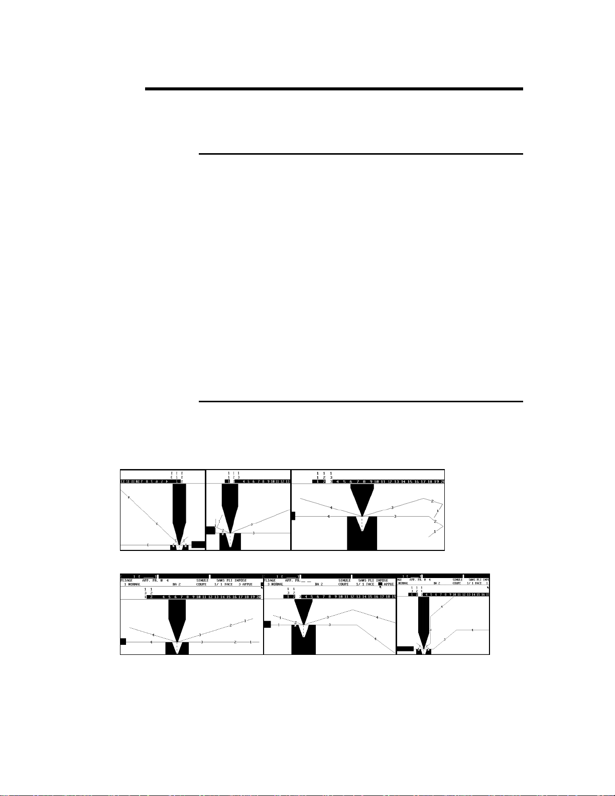
Below a simple example in which the product touches the table frame before
the bend, however the sheet is put. The solution for this product is to create
an intermediate bend. This so lution is described in Special bends.
This section only shows how to use the unbend function.
st
In the 1
already touches at the 2
figure, the product touches at the last bend, in the 2nd figure it
nd
bend.
DEFINITIONS PAGE 27
Page 32

Below are the data of the product (the die height is 50 mm).
In BEND 2D page, when asking to search a bending order, the message
Solution not found is displayed.
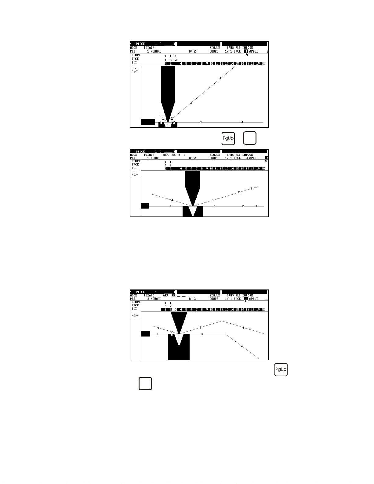
Select UNBEND mode.
The last bend is displayed, you immediately can remark the collision.
If a solution without collision is displayed, press the
key and
see if the software furnishes a solution. If no solution is proposed, that
means that there is collision.
Program or change in the FACE field the different faces and see
which possibilities exist.
Press the
key to move in the previous sequence.
If the software finds a solution, this will be displayed immediately as
well as the other possible faces (field PR FACE = proposed face).
In unbend mode the proposed faces are displayed in the PR FACE field. So
the operator can introduce one by one the proposed faces in the FACE field,
in order to see the result.
PAGE 28 2D REFERENCE MANUAL MODEVA/DNC 880S
Page 33

BENDING SPEED
Page: BEND NUM
This field allows to reduce the bending speed. It is programm able in % of the
maximum bending speed.
BG (BACKGAUGE) OR STOP
Pages: BEND NUM, BEND 2D
Displays or allows to select the stop for the current sequence.
The DNC recalculates the target value of the X and R axes as a function of
the choice.
Display the round robin list and choose a stop appropriate for the sequence.
This field will not appear if only one stop is defined in the machine
parameters.
Changing the stop on the BEND 2D page
See also Bending Order.
Introduce the designation of the required stop or select it in the round
robin list.
Leg
Support
DEFINITIONS PAGE 29
Page 34

BOTTOMING
Page: BEND NUM.
The bend by bottoming is a bending mode in which the DNC does not aim
for a predefined or calculated position to be reached, but descends until it
reaches a position which mechanically prohibits the beam from going any
further. The DNC detects this stop; and this determines the end of the descent
cycle.
The bend by bottoming allows to obtain special bends which it is not possi ble
to obtain in any other manner, such as the flattened bend in a special die, but
this technique involves certain risks.
In bottoming mode the beam furnishes the tonnage
programmed in the sequence or
pressures of the machin e parameters a re higher than those
of the current sequence.
The DNC stops the beam descent cycle when it realizes that it
is immobilized mechanically on the object to be worked.
Which means that the totality of the programmed force will be
exerted on this object and in consequence on the tools.
You must be aware that the sheet and the tools solicited in this
operation must be capable of supporting such a force without
damage.
Also, if the work does not need the whole bending length of
the machine, it is absolutely necessary to position everything in
the middle of the machine.
To execute a bend in bottoming mode:
erase the programmed angle (empty field),
then erase the MEM values of Y1 and Y2 (empty fields).
The cycle is effectuated normally but after passing the pinch point, the DNC
monitors the beam displaceme nt.
As soon as the beam has stopped and no longer sends any displacement
information to the DNC, the DNC considers that the operation has ended, the
dwell time is executed and the ascent cycle is activated according to the
chosen mode.
higher, if the minimum
PAGE 30 2D REFERENCE MANUAL MODEVA/DNC 880S
Page 35

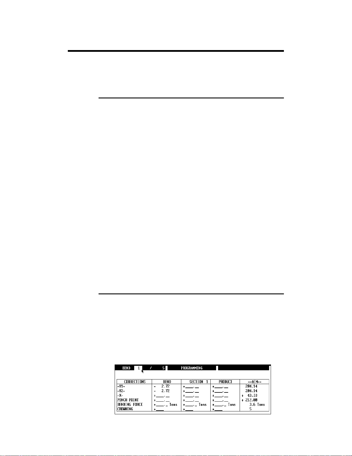
CORRECTIONS (TABLE)
During practical work it can sometimes be found that certain angles and/or
flap lengths often or always need to be adjusted by the same value.
In order for the operator to avoid never-ending corrections, a correction table
is available to him. The table is called MATERIAL and can be reached via
the machine parameters.
5 types of material are pre-programmed:
STEEL
ALUMINIUM
SS
SPECIAL 1
SPECIAL 2
For each of these materials, the tables of the MATERIAL are different.
The main items within this page are 3 tables:
UNFOLDED LENGTH By means of 10 columns (0 to 9), it is possible
to apply 10 different corrections to the
DIN 6935 calculation of the unbended length.
In the example shown above, if the chosen
material is STEEL 3, the correctio n will be:
DIN * 0.850.
The choice of the correction can be entered in
pages such as PROD NUM, BEND NUM, etc.,
in the field immediately following the material
designation.
DEFINITIONS PAGE 31
Page 36

SPRINGBACK
COMPENSATION
PRESSURE
PP TOLERANCE IN %
OF THICKNESS
THICKNESS
CORRECTION
FACTOR
Allows to define an angle correction for each
type of material, according to the programmed
angle. In the example shown above, the angles
comprised between 76° and 90° and which use
the material named STEEL will be corrected
automatically by -2.5°.
These two factors replace the calculation of the
bending force normally carried out by the DNC.
If they are not programmed, these two values
will be:
AIR BENDING = 1.75
BOTTOMING = 42.0
If necessary, these values can be changed by the
operator. These two values are specific to each
of the 5 material types.
This field represents a safety factor for the
tools. See the section Corrections by Thickness
Measurement / Measuring at the PP.
This table is used by the "thickness correction at
PP" function. See the sectio n Corrections by
Thickness Measurement / Measuring at the PP.
CROWNING
Page: BEND NUM.
Only valid if your machine is equipped with a crowning option.
The crowning is calculated automatically during simulation. The result is a
function of the applied force and the calibration curve programmed in the
machine parameters.
The operator can modify these values sequence by sequence, however they
will be recalculated during the next simulation.
The working units can vary depending on the constructor, to know the use of
this function, please consult the manufacturer of your machine.
However, the "per cent" is currently used as unit, that means that 50
programmed in this field will gi ve 50% of t he maximum crowning.
DATA BACKUP
See Data Transfer.
PAGE 32 2D REFERENCE MANUAL MODEVA/DNC 880S
Page 37

DATA TRANSFER
Page: TRANSFER
From this page data can be saved or loaded in the different peripherals.
(Diskette, Network, etc.)
Source
This field selects the peripheral which will supply the data to the destination
peripheral at the time of the transfer.
Destination
This field selects the peripheral which will receive the data at the time of the
transfer.
Global transfer
The choices are:
PUNCHES
DIES
SELECTED TOOLS
LIST OF
PERIPHERALS
MACHINE
PARAMETERS
PRODUCTION
ALL THE PRODUCTS
AND THE GROUPS
Transfer of all the punches.
Transfer of all the dies.
Transfer of the tools defined in multisimulation.
Transfer of the list of peripherals.
Transfer of the machine parameters.
Transfer of the production pages.
Global transfer of all the products and groups of
products.
Partial transfer
Select the transfer of the products mentioned in the table below.
In this table it can be specified for each product the source and the
destination in the respective columns. If these fields are not specified, it is t he
choice of SOURCE and DESTINATION at the top of the page which is
used by default.
To simplify the selection of the products to be transferred, simply “mark”
them on the PRODUCT LIST page. They will automatically appear in this
table (see Marking products).
DEFINITIONS PAGE 33
Page 38

The STATUS column gives the state of the transfer.
?
!
*
Making a transfer:
Recommendations:
Make a backup of the tools, the machine parameters and the li st of
peripherals (if your DNC is on a network) just after the first installation and
before the intervention of a technician. Keep this information in a safe place.
Save the products periodically on a floppy disk if your DNC is not connected
to a network. Its simple, fast and less expensive than having to reintroduce
everything if any problems arise.
The product is being transferred.
The product has not been transferred.
(Double definition in the list or another error).
An error has been detected during the transfer phase,
it has not been transferred.
The product has been transferred correctly.
Select the SOURCE and the DESTINATION.
Position the cursor on the type of transfer chosen.
Start the transfer using the TRANSFER function in the Action menu,
then confirm.
PAGE 34 2D REFERENCE MANUAL MODEVA/DNC 880S
Page 39

DATE AND HOUR
Change Date and Hour
Page: WELCOME
Call the WELCOME page.
Position the cursor in the upper part of the screen on the Date or Hour
field and enter the new value, thereby respecting the format.
On the DNC, the locking key must be set on position 2. Use the
key as separator.
Year 2000 When the year format uses two digits only, the software assumes that:
00 to 68 = 2000 to 2068
and
82 to 99 = 1982 to 1999.
Change Date and Hour Display Format
Sub-page of the WELCOME page.
To modify the date and the hour of the numerical control:
Call the WELCOME page and select DATE/TIME in the ACTION
menu.
A new screen appears on which the context of the DNC can be parametered.
(International parametering).
It is possible to load the default parameters by actioning the DEFAULT
function in the ACTION menu.
Classification,
search
DEFINITIONS PAGE 35
To facilitate the classification or the search for programmed products (by
date / hour), it is strongly recommended to put the DNC or the PC to the
correct time regularly (about every 3 months or after an intervention).
Page 40

DECENTERED PUNCHES & BACKGAUGE
CORRECTION
Page: PUNCH PROGRAMMING
The field, named X CORRECTION allows the user to carry out a correction
if a punch is decentered.
This correction applies to the backgauge a "modification of origin" according
to the decentering of the punch. It also takes into account the mounting
direction of the tool.
The correction becomes effective when the control switches to semi-auto or
automatic mode.
DEPTH COLLISION AUTHORIZED
Pages: TOOL BEND, PROGRAMMING PUNCH / DIE
The software generates an error message if it detects a collision of the
material at the bottom of the die and / or between the lateral faces of the
punch and the die. This message is displayed in the interacti ve field. The
software switches to the TOOL BEND page with the cursor pointing to this
field.
By default if nothing is specified, the collision test is m ade on each bend.
On the TOOL BEND page the DEPTH COLLISION AUTHORIZED field
is equal to ON THIS BEND NO.
However it is possible to inhibit this safety measure on the TOOL BEND
page for the current product (see below) or by default on the
PROGRAMMING PUNCH or DIE page.
PAGE 36 2D REFERENCE MANUAL MODEVA/DNC 880S
Page 41

TOOL BEND Page
Two choices are availabl e:
ON THIS BEND /
YES / NO
GLOBALLY
The collision test is made (or not depending on
the choice YES / NO) only on the current
sequence (bend).
The collision test is ignored for all of the
sequences constituting the product.
DRAWING
Side collision Bottom of the die collision
PROGRAMMING PUNCH / DIE Page
If the collision test is generally not desirable, it is possible to arrange for it to
be ignored by default when a product is created.
To create this situation when creating the tool you must program DEPTH
COLLISION AUTHORIZED YES.
For this authorization to be valid (on the TOOL BEND page), the punch and
the die must both have this authorization.
If one or the other of the tools does not give this authorization, then it is NO
which is again valid.
Pages: On most pages.
This field allows to enter an alphanumerical referenc e 24 characters (see
Alphanumeric Fields).
It is recommended to use this possibility to define a product in a unique
manner when a large number of products are dealt with. This facilitates
searching using product search criteria.
DEFINITIONS PAGE 37
Page 42

DWELL TIME
Page: BEND NUM
Defines the dwell time.
If not programmed, the default value is 0.5 seconds.
Other values between 0.0 and 9.9 seconds can be entered.
ERASE / DELETE
These operations are available in the ACTION menu, they vary according to
the context. Below you will find the definitions of these actions.
ERASE BEND Erases the contents of all the fields, but the
ERASE SECTION Erases the data (bending order) of the selected
ERASE PRODUCT Erases the contents of the work memory.
DELETE BEND De le te s th e se le cte d sequence (with automatic
DELETE SECTION Deletes the selected section.
DELETE PRODUCT Deletes the selected product.
DELETE Depending on which field the cursor is located,
sequence remains.
section.
recompacting of the remaining sequences).
On the PRODUCT LIST page, it is possible to
delete a product by placing the cursor directly
on the required number in the list.
deletes the selected punch, die or product.
PAGE 38 2D REFERENCE MANUAL MODEVA/DNC 880S
Page 43

ERASING MEMORIES
Page: MACHINE INITIALIZATION - DNC/ENC
General remarks:
This page allows to empty (erase) different memories. Depending on the type
of erasure, it is necessary to have the key in position 1, 2 or 3.
To delete the contents of one or all the memories:
Select the peripheral in which the operation is to be made.
Place the cursor on the relevant field.
Click right or
Confirm.
FREE MEMORY
Pages: PRODUCT LIST, WELCOME
Indicates to the operator the quantity of available free memory, given as a %
for the selected peripheral.
key or Action menu DELETE.
DEFINITIONS PAGE 39
Page 44

GAUGE CLEARANCE
Page: BEND TOOLS
Reminder: the following movements are considered to be dangerous and thus
to require die clearance: displacement of Z, M1 and M2 axes, as well as the
auxiliary function of the DIE type.
In order to offer functionalities adapted to particular needs, the operator now
has the possibility of specifying the type of gauge clearance.
The operator can make his choice for each sequence within the BEND
TOOLS page, on the X CLEARANCE field.
Attention:
The clearance distances (parameter 233) are programmed in the machine
parameters, they must not be changed.
Three types of clearance are available:
MAXIMUM
OUTSIDE CLEARANCE
ZONE
NONE
PM 5 0
Default value.
In this case, the die clearance is made according
to the higher value of the two parameters
X Position for Safety Spee d and
X Position for die clearance.
Normally, the X Position for Safety Speed
is the higher of both values.
Afterwards, the axes move at maximum speed.
Clearance until X Position for die
clearance.
Then the axes move at the speed authorized
within the X Position for die clearance
zone.
This type of clearance should be used when
there are only small distances to be covered.
There is no clearance at all. The axes will move
at safety speed when they are located within the
X Position for Safety Spee d zone.
PM 5 0
PM 5 0
PM 2 3 3
PM 2 3 3
The clearance distance is dependent on the die width. If several posts are mounted,
the distance takes into account the largest of the tools.
PM 50 and PM 233 are the numbers of the concerned machine parameters.
PAGE 40 2D REFERENCE MANUAL MODEVA/DNC 880S
PM 2 3 3
Page 45

IDEAL CURVE (CR)
Pages: PRODUCT NUMERIC and BEND NUM.
The ideal curve allows to make a bend with a large internal radius.
An ideal curve can be programmed on one or the other of these pages.
An ideal curve is defined by programming from 4 to 98 (programming 0, 2
or 3 will give an error).
Remark: For the result to be coherent, the number of bends to realize the
angle must be such that the length of each segment is greater
than half the length of the V opening of the die.
If this is not the case a message informs the operator and the
result will be an angle too open.
Tips If 99 is programmed in the CR field, the software automatically determines
the maximum of bends for the ideal curve. Of course the operator can reduce
the number of bends.
In ideal curve mode, the software calculates different bends for the first,
second, next but last and last bend according to the drawing which follows.
Procedure for realizing an ideal curve
PRODUCT NUM Page
Call the PRODUCT NUM page.
Introduce the value of the required segment in the L column.
Introduce the final angle required.
Introduce the final internal radius in the Ri field.
Introduce the number of bends for the ideal curve in the CR field.
See also Tolerance.
DEFINITIONS PAGE 41
Page 46

Programming example
Call the PRODUCT NUM page.
Introduce the tools and the material in the usual way.
Introduce the product dimensions with the internal radius of the ideal
curve in the Ri column.
Introduce 99 in the CR field, the softwar e will calculate the maximum
number of bends for this ideal curve (see fig. above).
Start the calculation (via Action menu) to obtain the unfolded length,
the tolerance (see Tolerance) and the number of bends for the ideal
curve.
Call the BEND 2D page.
Make sure that the SIMULE field is on WITHOUT IMPOSED
BEND.
Choose SEARCH BENDING ORDER (via the Action menu).
Then pass in semi-automatic
to programming mode).
Simulate the bending with the
PAGE 42 2D REFERENCE MANUAL MODEVA/DNC 880S
(on PC key F8 and F10 to return
key.
Page 47

Programming example for a gutter
To realize the above type of product:
Call the PRODUCT NUM page.
Introduce the tools and the material in the usual way.
Introduce the product dimensions with the internal radius of the ideal
curve.
Introduce 99 in the CR field, the software will c alc ulate the maximum
number of bends for this ideal curve (see fig. above).
Start the calculation to obtain the unfolded length, the tolerance and
the number of bends for the ideal curve.
Call the BEND 2D page.
In the actual state of the software, the automatic simulation of this example
product will not give a result.
The UNBEND mode must be used to impose semi-automatically the order of
bends. In the example below, the bending order has not been modified. The
operator is free to do so during this procedure.
DEFINITIONS PAGE 43
Page 48

Select UNBEND mode.
The product is displayed in the tools with the last programmed bend.
Introduce the face which must be bent last (3 in this example)
When leaving the FACE field, the software displays the chosen bend.
Place the cursor on the STOP field and modify the stop if necessary.
For this product the stop 4 proposed automatically has been
conserved.
In spite of the "collision" visible in this situation, there will not be any
collision due to the ideal curve (see further on under simulation in
semi-automatic mode).
Press the
The software displays the previous bend (another bend can be selected
by programming in the face field the one required). The proposed stop
(5) is conserved but can also be modified.
key.
PAGE 44 2D REFERENCE MANUAL MODEVA/DNC 880S
Page 49

Repeat the operation above until you have reached bend No 1.
Change to semi-automatic mode
Visualize the result step by step by pressing the
(on PC press F8).
Pg Dn
key for each
bend made. (On PC, to return to programming mode press F10).
Remark: In this example, the stop is equipped with an R axis. The
software thus calculates its position automatically as a function
of the ideal curve. If your DNC is not equipped with an R axis,
a vertical stop can be fixed perpendicular to the original stop.
DEFINITIONS PAGE 45
Page 50

INDEXING AXES
Page: MACHINE INITIALIZATION DNC / ENC, Action menu.
The INDEX AXES function allows to index or index the axes once again (if
already done).
If the DNC has not been indexed, this function will have the same effect as if
the Start button
If the DNC is already indexed, this function allows to re-index the axes
without switching the power off. In this case the DNC will ask the operator
to confirm this operation. Make sure that the beam is loca ted underneath the
indexes !
had been pressed in order to index the DNC.
INSERTING A SEQUENCE
BEND NUM page
To insert a sequence:
Position the cursor in the BEND field, then take position on the
sequence you wish to insert (for example 2) using the
key.
Select INSERT BEND (Action menu).
The inserted sequence will take place 2 in our example and displace the
sequence 2 to position 3. An inserted sequence is empty.
If you wish to insert a sequence and copy its contents, you must proceed in
the same way, but you must choose COPY A BEND (Action menu).
or
BEND 2D page
This possibility is used, for example, for effectuating special work
(Punching, modelling, etc.) which cannot be represented graphically.
On the BEND 2D page, if a sequence is inserted, the graphic of the previous
sequence is always displayed.
This sequence will NOT be represented graphically.
A sequence inserted in this way is empty. You must go to the BEND NUM
page to modify the inserted sequence.
PAGE 46 2D REFERENCE MANUAL MODEVA/DNC 880S
Page 51

To insert a sequence:
Position the cursor in the BEND field, then take position on the
sequence you wish to insert (for example 2) using the
key.
Select INSERT BEND (Action menu).
The inserted sequence will take place 2 in our example and displace the
sequence 2 to position 3. An inserted sequence is empty.
INTERNAL RADIUS
Pages: PRODUCT NUM, BEND NUM
The internal radius is calculated automatically as a function of the sheet
metal thickness and the tools. This calculated radius is only valid for air
bends.
or
Ri
If the radius of the punch is greater than the natural internal radius of the
sheet, it is that of the punch which takes precedence.
It is possible to impose the radius in order to adapt the calculation of the
unfolded length and the calculation of the stop positions at best for a
particular material. To do this:
Program the radius in the relevant field.
Program the CR field at 1.
DEFINITIONS PAGE 47
Page 52

KEYBOARD
External keyboard for the DNC
In case of necessity, it is possible to connect a 100% PC AT compati ble
external keyboard to the rear of the numerical control..
Attention: The DNC must be disconnected from the power supply to
connect the keyboard, otherwise correct functioning may be
impeded.
When an external keyboard is connected to the DNC, the front panel of the
numerical control remains perm anently active.
L. BENDING
Pages: PRODUCT NUM, BEND NUM
Bending length, sometimes called "bending width", means the distance
between the two extremities of a bend.
If the product is programmed on the PRODUCT NUM or BEND NUM
page, the bending length must be entered by the operator.
This value is indispensab le f o r the software to be able to aut o matical ly
calculate the pressure, the crowning and or the axis separation (Z1 and Z2) of
the machine.
With the 3D software version and if the programming is realized in 3D, this
value is treated automatically by th e software.
PAGE 48 2D REFERENCE MANUAL MODEVA/DNC 880S
Page 53

LANGUAGE
Pages: WELCOME or MACHINE PARAMET E RS
The software generally possesses a choice of several languages.
The composition of these languages varies depending on the manufa cturers
request.
To switch languages:
Call the WELCOME page.
Key on position 2.
Place the cursor on the LANGUAGE field.
Press the
the available languages.
Place the cursor on the language required.
Validate the selection using the
key or click right to display the round robin list with
LEAVING THE SOFTWARE
To switch off he machine proceed as follows:
For safety reasons:
Lower the machine beam in to the tools or on to the blocks of wood or
metal.
Stop the main motor.
Press the MENU
Validate with the
In the new window select TERMINATE.
Validate with the
Wait until the screen of the DNC becomes black and gives the
message EXECUTION TERMINATED. Under Windows, the DNC
will automatically leave Windows and give a message when the
system is ready to switch off the supply.
Switch off the mains supply to the DNC or the machine.
key.
key and select QUIT.
key.
key.
DEFINITIONS PAGE 49
Page 54

On a PC proceed in the same way or:
LEG
Press simultaneously the
Click on TERMINATE.
Page: BEND 2D
Allows to select a different leg than the one displayed for the current
sequence. See also Bending Order and BG (Backgauge) or STOP.
Select the required bend using the
and keys.
and key.
Leg on the 0 face
Place the cursor in the LEG field.
Introduce the N° of the face which must be resting on the back gauge
(3 in this example).
Press the
key to validate the modification.
Modified leg
PAGE 50 2D REFERENCE MANUAL MODEVA/DNC 880S
Page 55

LENGTH
Page: PRODUCT NUMERICAL
This field expresses the length of a segment (see examples in the User
Manual) and indicates that you are in L-alpha mode. That is a length is
entered, then the corresponding angle, the following length, the angle, etc.
Sometimes the drawing which is used as a basis for the realization of the
product does not allow to program easily in the L-alpha method. You can
switch to the LU / LW cotation method using the LENGTH round robin list
and thus program in coordinates.
LW
LU
This is a facility which unfortunately is not standardized. The results can thus
vary slightly depending on the case.
LU
LW
LOW SPEED DISTANCE
Page: BEND NUM
Allows to define that only a portion (expressed in %) of the upward
movement between the lower dead center and the clamping point will be
carried out in low speed, the remainder of the upward movement being done
in high speed.
If BENDING SPEED has been programmed and LOW SPEED
DISTANCE is not programmed, the upward movement up to the
clamping point is carried out in low speed. (= 100%).
MACHINE PARAMETERS
Pages: MACHINE PARAMETER
These pages contain the parameters necessary for the functioni ng of your
machine. It is very important to have a backup copy on disket te (see Data
Transfer). If any problems occur, you will save a lot of time if you have to
re-introduce them.
Under no circumstances should the machine parame ters be modified
without the consent and the support of the machine manufacturer.
Erroneous programming can cause important damage to the material
or render the machine dangerous.
DEFINITIONS PAGE 51
Page 56

MAINTENANCE
Maintenance of the numerical control is restricte d to the changing of the
filters and the cleaning of their housing at regular intervals.
Change of filters
It is important to regularly (o n c e per month) change the filters of the fans of
the numerical control. If this maintenance is neglected, the numerical control
might build up exaggerated heat and cause damage which can sometimes be
irreversible.
Interrupt the main power supply.
Remove the 4 screws of the protection grid.
Change the filter.
Install the protection grid again.
Cleaning of the DNC
Interrupt the main power supply.
Clean the keyboard, the casing and the rear panel with a humid cloth and
some liquid soap.
Dry with a clean and dry cloth.
Never use alcohol-based products nor solvents (trichlorethylene,
thinner, acetone or the like).
MANUAL ADJUSTMENT OF THE BACKGAUGE
In many cases, the backgauges are not equipped with Z axes enabling lateral
displacement of the gauge fingers. In other cases, the operator m ust change
the gauge configuration by hand or add some accessories. To do this, he had
to either intervene from behind the machine, or else stretch his arms across
the machine below the b eam.
In order to facilitate thi s task and to provide increased safety, it is now
possible to program specific positions for the X and R axes and/or auxiliary
functions in GAUGE management mode.
The purpose of this is to place the backgauge forwards above the die
(provided that the machine allows for this possibility), so as to enable the
operator to carry out his task easily and without danger staying in front of the
machine.
PAGE 52 2D REFERENCE MANUAL MODEVA/DNC 880S
Page 57

Ideally, the machine manufacturer would conc eive a mechanical or
electric/pneumatic system that unlocks the gauge fingers within this
adjustment position, and locks them again once the gauge is leaving this
location.
The gauge positions for this operation can be programmed in the ma chine
parameters page called SP ECIAL CY CLES.
The beam must be located in its max. TDC.
When the numerical control is in semi-automatic or automatic mode,
the operator activates this special cycle from the BE ND NUM page
by means of the ADJ.GAUGE function (ACTION menu).
The operator will then have to confirm each step of this cycle by
clicking inside the appropriate dialogue window.
At the end of the cycle, the gauge returns to its orig in al location.
MODIFYING THE ORIGIN OF THE AXES
Page: MACHINE INITIALIZATION DNC/ENC
General remarks:
This page allows to modify the origin of the axes of the machine, to consult
the position of the axes (POSITION field), the index (INDEX field) and the
limit switches (LIMIT+ and LIMIT- fields).
The second part dealing with erasing the memorie s i s dealt with in the
Erasing Memories section.
It is understood by "modification of the origin" (also called "setting an axis")
to impose a value (at the moment of the operation) in the electronic position
counter of the numeric control. This operation is used to correspond the
mechanical position of the axis with the position of the electronic counter.
This procedure is usually done for the stop axes or the auxiliary axes. For the
beam, the latter executes automatically during indexation of the beam.
Setting an axis is most often used to correct a shift of the back gauge. That is
to arrange that when the X axis indicates 0.00 on the position counter, the
backgauge is situated exactly on the bending line (this definition is valid for
the LEG type of stop).
If this is a temporary change (caused by a shifted tool for example ), it is
recommended to use corrections rather than setting the axis.
DEFINITIONS PAGE 53
Page 58

Attention: certain manufacturers equip the back gauge with an index.
In this case modifying the axis origin will only have a limited effect just until
the next indexing.
If you have to permanently modify the origin of an axi s, please contact the
machine manufacturer.
Setting an axis modifies the origin of the axis. If this operation is
incorrect, it can damage the machine and/or the tools. The axis can for
example enter into collision mechanically with another element. In the least
case, the products produced will be inexact.
Setting an axis must thus be done with precaution. The person who
undertakes this operation must be perfectly awa re of the consequences.
To modify the origin of the axes, proceed as follows:
Check that the axis concerned is no longer in movement.
Change the numerical control to programming mode.
Access the MACHINE INITIALIZATION page.
Key on position 3.
Place the cursor on the required axis in the REQUESTED column.
Introduce the new position.
Action menu: Select VALIDATE.
The new position is displayed in the POSITION column.
To control the new origin of the axis proceed as follows:
Remain on the MACHINE INITIALIZATION page.
Change the numerical control to manual mode.
Place the cursor on the required axis in the REQUESTED column.
Introduce a value to be reached.
Press the
key on the front panel.
The axis must move to the requested position.
Control the result and correct if necessary.
PAGE 54 2D REFERENCE MANUAL MODEVA/DNC 880S
Page 59

PARAMETRIC PRODUCT
Function:
Possible only in 2D mode.
Enables a simply and rapid modification of a given and repeated profile by
programming only predefined parameters.
On the basis of a product created in PRODUCT NUMERICAL, the operator
has access to the modifications of the product, but only on parameters which
have been defined with minimum and maximum values in the parametric
product. The activation or disactivation of this function requires the key in
position 3.
Activation of the function
Parametric product
Call the MACHINE P ARAME T ER S.
With the help of the
presented window and select the option YES next to the Product
parametric field.
and keys, display the above
Create a parametric product
To create a parametric product, proceed as follows:
1. Creation of the numerical product in the usual manner.
2. Definition of the parameters.
3. Activation of the parameters.
4. Memorization of the product.
5. Working with the parametric product.
DEFINITIONS PAGE 55
Page 60

Step by step:
Example of a profile
Press the function key PRODUCT (
PRODUCT NUMERICAL.
Below, a model profile of a product that often will be manufactured, but
whereof certain parameters have to be modified, according to the
demand.
) and select
Press the function key PRODUCT (
PARAMETERS PRODUCT NUM as below.
) and select
PAGE 56 2D REFERENCE MANUAL MODEVA/DNC 880S
Page 61

The parameters A to H
are those 8 parameters
which afterwards can
be modified.
Columns:
Caption: enables to
briefly describe the
modifiable parameter.
Min, Max, Suggested
enable to fix limits and
a default value.
The following window opens:
Decide and fill in the fields of the parameters you wish to make
modifiable.
Click right or
to
select the parameter
to be associated with
the face.
Associate the defined parameters with the different faces and angles
you wish to change. By opening the choice list, choose in the
concerned field the variable parameter which will be associated with
this field.
DEFINITIONS PAGE 57
Page 62

For example:
Face 1 associated with parameter A.
Faces 3, 5 and 6 associated with parameter B.
Face 4 associated with parameter C.
Angle face 2 associated with parameter D.
After having finished the definition of the parameters, it is advisable to
activate them, in order to make the product parametrable.
Activate the parameters. PARAMETERS: ACTIVE.
Press the function key PRODUCT (
) and select
PRODUCT NUMERICAL.
The product numerical page has now changed, only the previously defined
parameters are displayed and modifiable.
PAGE 58 2D REFERENCE MANUAL MODEVA/DNC 880S
Page 63

Working with a parametric product
As for a normal product, place the cursor on the VALUE field of the
parameter you wish to modify.
On the profile drawing, a circle indicates the face associated with this
parameter. Enter the new value and leave the field.
The system recalculates automatically the new profile as well as the
new unfolded length.
If you wish to change other values, or to modify the product profile, you
have to disactivate the PARAMETERS function in the PARAMETERS
PRODUCT NUM page.
DEFINITIONS PAGE 59
Page 64

PRODUCT GROUPS
Page: PRODUCTS GROUP via PRODUCT menu.
This page allows to create groups of products in order to realize sets.
Definitions
A group is represented by a list of product numbers and typically
corresponds to an assembly of several parts.
Any one product can be part of several groups.
In a given group, a product can be present several times.
During execution of a group, the products can be chained either
automatically, or only upon the operator's request (manual chaining).
It is possible to define several groups. The groups must be given a number
which is greater than 90000.
A "quantity needed" and a "quantity done" can be assigned to each defined
group.
Chainings:
1. Automatic chaining:
The parts are produced in the quantity and in the order in which they
appear within the group.
The groups are produced one after the other until the required quantity
has been reached.
2. Manual chaining:
After each produced part, the operator explicitly designates the next part
to be carried out.
In the example above the DNC executes twice the product 1 (24031), then
once the product 2 (24033), and finally five times the product 3 (24034), and
then recommences 56 times.
2 x
24031
PAGE 60 2D REFERENCE MANUAL MODEVA/DNC 880S
56 x
1 x
24033
5 x
24034
Page 65

T o create a group of products:
Column PRODUCT: enter the product number (the product must
exist).
Field QUANTITY NEEDED: enter the number of sets required.
Field QUANTITY DONE: enter the number of sets which have
possibly already been produced.
Memorize the group under a number between 90'000 and 99'999.
The function key DRAWING GR. (only 3D version) displays graphically
the outline of the products (for as much as these products were created in 3D)
forming the group.
The AUTOMATIC PRODUCT CHAINING field indicates to the DNC that
it can automatically chain the products i n the order described in the table
(see example above).
The MANUAL PRODUCT CHAINING field causes that the DNC
effectuates the number of products specified in the table, then at the end of
that series it displays the PRODUCT GROUP page with the cursor on the
PRODUCT column (even in automatic mode). The operator must then select
another product and press the
112 x
24031
The NEXT GROUP field is only an information field which allows to
specify to the operator the following group of products to be realized.
key to load and execute the said product.
56 x
24033
280 x
24034
Working example in the PRODUCTS GROUP page
Edit a group composed of a set of products (make sure that all the
products have been defined beforehand).
Pass in automatic mode
If the group contains any errors, the message "INCOMPLETE
GROUP" appears on the screen.
It is possible to choose the first product to be executed by positioning
the cursor on the product before pressing the auto
.
key.
The semi-auto
In order to allow that the execution can be resumed according to the
chaining mode, it is necessary to memorize the group in the moment
of interruption (this will make sure the quantiti es needed and the
quantities done be saved).
DEFINITIONS PAGE 61
and manual keys interrupt the execution.
Page 66

PRODUCT INFORMATION
Almost all pages: ? or ! Field (situated in the left hand corner of the screen).
For each product saved, commentaries and / or images can be annexe d in
order to furnish the operator specific information for that product..
In this way the information is permanently avai lable.
Two main possibilities are offered:
Text
Text only
In this case only the small window appears.
Text and images
Text and images
In this case the complete page is displayed.
With this choice, it is possible to display photographs, drawings or other
graphical information. The software automatically recognizes the DXF,
IGES and PCX file formats (see PCX Files or DXF and IGES Files
which follow in this chapter).
PAGE 62 2D REFERENCE MANUAL MODEVA/DNC 880S
Page 67

See an Information
Move the cursor on to the ? or ! symbol and press the key or
click.
If information is available the ? field changes into a ! field.
It is possible to display the PRODUCT INFORMATION window
automatically (only if it contains a commentary) each time the operator calls
a product. To do this, you must program in the machine parameters, on the
CONFIGURATION page, the parameter Automatic display of product
information at YES.
Creating an Information (text only)
Display the PRODUCT INFORMATION window (c lick on ?).
Click on VISUALIZE and select EDIT (on the DNC: key on 2).
Select SIMPLE in the round robin list field.
Create the text. At the end of each line go to the next line by pressing
Programming info
and / or images
the
Click on EDIT to go in to VISUALIZE mode then leave.
key.
Creating an Information (text and images)
In the procedure described below, it is accepted that the photographs (drawings or
images) have already been created and their location is known (see also Active
Peripherals).
For the creation of numerical photographs or images etc., you must refer to the
apparatus documentation as well as to the software associated with the apparatus
(numerical camera, scanner etc.) or to the drawing software for the creation of
graphical information.
It is recommended to store the images on a server (connected to the DNC by a
network) and not in the internal memory of the numerical control, as image
files occupy a lot of space.
DEFINITIONS PAGE 63
Page 68

To introduce the images:
Display the PRODUCT INFORMATION window.
Click on VISUALIZE and select EDIT (on the DNC: key on 2).
Select WITH COMPLEMENTS in the round robin list field.
Create the explanation text.
Position the key on 1 or 0 or click on EDIT and select VISUALIZE to
secure the message.
Introduce on one line the name of the graphic file (1 per line)
With or without generic characters (* or ?). See further below the
explanations about generic characters and where the software has to
search the image files.
In the above example, >P256.PCX indicates to the software that it
must display the image in the P256.PCX file when the PRODUCT
INFORMATION page is first called.
To display the PLI3.PCX and PLI4.PCX images, position the cursor
on the relevant line and select DISPLAY via the Action menu.
Click on EDIT to go to VISUALIZE mode then leave.
The symbol > indicates that the image which follows will be displayed
automatically.
If the file name is indicated alone, the software will go and search for it on
the path described by the peripheral designated under the
COMPLEMENTS IN field (See Active Peripherals).
If the complete path is furnished, the software ignores the peripheral.
The generic characters * and ? allow to select several files.
To display them position the cursor on the line and press the
or
key.
PAGE 64 2D REFERENCE MANUAL MODEVA/DNC 880S
Page 69

For example *.PCX will display all the PCX files which are lo c at ed in the
directory designated by the path of the images peripheral.
1= Line which designates the file
to be displayed.
2= Name of the peripheral where
the files are located.
3= Name of the file currently
displayed on the screen.
4= Number and quantity of files
if the characters * or ? are
used.
PCX Files
The software allows the display of images in PCX format with 16 or 256
colours.
You can use for example an electronic camera and directly display these
photographs or other drawings in PCX bitmap mode furnished by a scanner
or graphics software.
Example of reading a
DXF file
DXF or IGES Files
The software recognizes automaticall y files in DXF or IGES format.
Only files in 2D are recognized. Depending on the software used to create
these files, it is possible that some parts of the drawing are ignored or deleted
by our interface.
To obtain more information about the reading possibilities of the DXF or
IGES files, request the CYCAD manual which describes the possibilities,
compatibility and limits of inter pretation.
DEFINITIONS PAGE 65
Page 70

PRODUCT MANAGEMENT
Pages: most pages.
In all pages which mention the product number (PRODUCT field top ri ght),
the searching, the saving or the deleting is normally possible.
This operation is done in the default memory (generally INTERNAL).
However an other memory could have been selected as default memory. In
this case these operations will be done in the memory designated by the
active peripheral (see Active Peripherals).
It is possible to carry out these operations in a memory other than the default
memory. However this possibility only exists on the PRODUCT LIST or
TRANSFER pages.
Saving, searching or deleting a product on a floppy or a network
Page: PRODUCT LIST
Place the cursor on the PRODUCTS AND GROUP IN INTERNAL
field.
Choose the required peripheral.
Number of
products in
the current
peripheral
Current
peripheral
Next call, save or delete the product.
The authorized range for saving products goes from 1 to 89'999.
The numbers 90'000 to 99'999 are reserved for the product groups
(see Product Groups).
To facilitate searching, it is recommended to add a drawing code before
saving (see also Searching for Products according to Criteria and Active
Peripherals).
Copying a product
Call the product to be copied.
If necessary change the peripheral.
Program another product number and save it.
PAGE 66 2D REFERENCE MANUAL MODEVA/DNC 880S
Page 71

Marking products
To facilitate the transfer of products, it is possible to select in the current
peripheral the products to be transferred.
A "marked" product is designated by a small triangular mark
number.
The marked products are automatically reporte d on the TRANSFER page
where they appear in the transfer list. (See Data Transfer).
To mark or "unmark"products:
Cursor on the required number.
Use the ERASE MARKS command of the Action menu to delete all
Remark: Product marking is limited to 48 products.
key or click to mark or unmark.
the marks.
next to the
PROGRAMMING A PROFILE
See examples in the User Manual.
PROGRAMMING ON BEND NUM
To program a profile on the BEND NUM page, proceed as follows:
Call the BEND NUM page
Empty the programming memory.
(choice ERASE PRODUCT in the ACTION menu)
Enter the thickness, the sigma and the type of material.
Cursor on the PUNCH field. Press the
display the punch list, choose the required punch and validate with the
key.
key or click right to
DEFINITIONS PAGE 67
Page 72

Cursor on the DIE field. Press the
the die list, choose the required die and validate with the
Enter the required angle.
Enter the value of the back gauge.
Enter the values of the other axes (R, Z, etc.).
Enter the other functions of the sequence (Bending force, TDC, SP,
Axes wait, etc.).
To create a second sequence: select COPY BEND in the Action
menu. This operation copies the current sequence into the next
sequence with the same values. Simply modify t he values of this new
sequence and repeat the operation for the following sequences.
See also the examples in the User Manual.
PROGRAMMING WHILE WORKING
The DNC 80 / 800 / 880S / 900 / 1200 / ModEva allow to program the
numerical control while working.
To this end:
Program the machine parameter Programming while working (page
Preferences) = YES.
key or click right to display
key.
Pass on automatic mode: the LED of the
is working in automatic mode. The operator can bend.
Double mode
Pass on double mode by pressing the programming key .
The automatic LED is still lighting up and the LED of the programming key
is also active.
From now on it's possible to use the numerical control for program ming,
meanwhile the machine can continue to exe c ute the current product.
All the programming functions are accessible. Memorize, search, delete,
transfer, etc.
Return to single mode
From the double mode (visualized by the two LED's Automatic and
Programming simultaneously lighting up) press either the Programming key:
In this case the product in programming process is displayed,
or
Automatic: The product in executing process is displayed.
key is lighting up, the DNC
PAGE 68 2D REFERENCE MANUAL MODEVA/DNC 880S
Page 73

Q.NEEDED. ___ DONE.___
Page: BEND NUM
This field is a product counter. When this software functions on a numerical
control this counter displays the number of products already done.
To activate this counter:
Enter the number of products required in the Q.NEEDED field.
and
The quantity already done in the DONE field, or the value 0 if no
product has been created.
As soon as the two values are equal the numerical control furnishes a signal.
Depending on the manufacturer this signal is treated or not to stop the
machine cycle.
The values in this counter are not memorized with the product. You must
change or erase these values when you call a new product.
To cancel the counter, delete the DONE field.
REFERENCE YR COR.
Page: TOOL BEND
This field allows to correct the tool pair reference.
This correction is memorized with the product and not with the tools.
This correction also modifies the safety point, the pinch point and the bot tom dead
Pinch point before
correction of the
reference.
centre. This correction is to be used with precaution. An error in this field can
impede the correct functioning of the machine, cause i mportant material damage or
make the machine dangerous.
PCV
PSS
PCT
0 Référ ence
PCV
PSS
PCT
0 Réf.
PCV
PSS
PCT
0 Référence
Pinch point after
correction of the
reference.
It can be observed in this diagram that the correction of the reference
modifies all the switch points as well as the bottom dead centre.
DEFINITIONS PAGE 69
Page 74

SCREEN CAPTURE
The ModEva/DNC 880S software allows to copy screens easily to create
documents or other information (offers, etc.).
To capture the screens proceed as follows:
Start up the word processor or other software into which you wish to
import the screens.
Start up the ModEva/DNC 880S software.
Capture the active window by pressing the
The image is transferred to Windows clipboard.
Activate the software into which you want to insert the capture by
and
Print
Screen
keys.
pressing simultaneously the
times, according to your current applicati on.
Insert the image using the Paste function in the Edition menu of your
word processor. Reduce or cut the image according to your needs.
You also can use the screen capture tools specially destined to this type of
application and which can immediat ely convert the colour captures in grey
levels. These softwares are for example Corel Capture (included in Corel
Draw) or Hardcopy, a freeware software available on Internet
www.hardcopy.de
.
and keys once or several
BLACK AND WHITE, COLOUR
In order to facilitate the creation of illustrated documents with screen copies,
it is possible to switch the ModEva/DNC 880S software to black and white.
Proceed as follows:
Call the machine parameters, TESTCARD AND SCALES page.
Select BLACK/WHITE in the TEXT AND DRAWINGS field.
PAGE 70 2D REFERENCE MANUAL MODEVA/DNC 880S
Page 75

SCREEN PRINTING
It is advised to switch the software to BLA CK /WHITE before starting to
print.
Selecting a printer
Call the machine parameters, TESTCARD AND SCALES page.
Windows Version
The printer selecting under Windows is not effective. It is the printer
defined by default in the "Parameters – Printers" menu of Windows
which determines the printer.
Attention: if you change the printer ("Parameters – Printers" menu of
Windows) while ModEva/DNC 880S is working, you have to leave
and to start ModEva/DNC 880S again, in order that the new printer is
taken into account.
Select the destination. If the line is empty, PRN is used by default.
You can enter LPT1, LPT2 or the name of a file.
By entering NUL in the destination field, printing is prohibited and
the relevant line in the ACTION menu will disappear.
Printing
To print a page:
Select the relevant page.
DEFINITIONS PAGE 71
Page 76

Call the ACTION menu and select PRINT SCREEN.
To print all the parameter pages:
Go to the parameter page from which you wish to start (for example
the first page of the N2X parameters).
Call the ACTION menu and choose PRINT PARAMETERS.
The software will print one after another all the parameter pages
(including sub-pages).
You can stop printing by pressing any key (for example at the end of
the N2X parameters). Printing does not stop immediately, the current
page is terminated.
PAGE 72 2D REFERENCE MANUAL MODEVA/DNC 880S
Page 77

SEARCHING FOR PRODUCTS ACCORDING TO
CRITERIA
Page: SEARCH PRODUCTS/CRITERIA
This page allows to search for products stored in the peripheral selected in
the PRODUCT LIST AND GROUPS IN field.
The selection criteria can be combined. When 2 or several fields listed below
are filled, the product searched for must satisfy each of the programmed
criteria. It is a condition AND (one and the other fields.....).
Search criteria Are used as search criteria: the date of memorization, the product number,
the material thickness, the code number (drawing), the bending length, the
tools and the unfolded length.
Small letters are distinguished from capital letters.
Attention: searching with the criteria PUNCH or DIE, is only done on the
"main" tool which is programmed on the PRODUCT NUM page. This
means that if a product is programmed using only BEND NUM page and
you wish latter to search for this product using the tools, you must program
the "main" tool again on the PRODUCT NUM page, without which the
search will not find this product.
If the complete contents of the code number is not known, it is possible to
use the special characters (wildcards) to replace the unknown characters (for
the other fields if they are filled, the contents must be known entirely).
?
*
In the example below, it is supposed that the search criteria is only the
drawing number. It goes without saying that the “wildcards” can be used in
the other fields.
Example Explications
A?C*
*22 A product is searched for whose code ends with 22.
Any character (1 only).
None or several characters.
A product is to be searched for whose code starts with an
A, then an unknown character, , a C and then several
unknown characters.
(e.g. ABC, ACC22, AmCh22, A6CProduct33).
(e.g. ACC22, AmCh22, 22, Product22)
DEFINITIONS PAGE 73
Page 78

A?C*22 A product is searched for whose code begins with an A,
then an unknown character, a C and ends with 22
(e.g. ACC22, AmCh22, AVCProduct22).
*A?C*22 As above but A?C is not necessarily at the beginning
(e.g. ACC22, AmCh22, PARC22).
*A?C*22* As above , but 22 is not necessarily at the end.
(e.g. ACC22, AmCh22, PARC22bis).
MEMORIZATION DATE
The memorization date of a product can be used as a search criteria for
products. To do so a time span is specified in which the search for
information is made.
If the introduction syntax is wrong a message appears in the interactive field
"SYNTAX DATE!".
The introduction format is DD/MM/YY (D=day, M=month, Y=year).
On the numerical control the
days, months and years.
The choice of the type of separation is configurable on the WELCOME page.
or key can be used to separate the
PAGE 74 2D REFERENCE MANUAL MODEVA/DNC 880S
Page 79

SECTION
Pages: PRODUCT NUM and BEND 2D
A section is an imaginary line which "cuts" the product lengthways and
which defines a profile. It is this profile that the operator sees on the
BEND 2D page.
A product can have several sections (in the example below, 2 sections).
Each section is considered as a separate profile.
The operator will mainly use the PRODUCT NUM page to program one or
more profiles (see the manual User Guide and Programming a profile in this
manual).
The creation of the sections is automatic if the product is programmed in 3D.
SIGMA
45
Pages: PRODUCT NUM and BEND NUM
2
Enter in this field the value in Kg/mm
product.
Example:
Steel AC37-2 K 38,22 Kg/mm
Stainless steel X5CrNiS18 8 51 à 71 Kg/mm2
Aluminium ALMg2,7Mn 24,97 Kg/mm2
of the material used to effectuate the
2
DEFINITIONS PAGE 75
Page 80

SIMULATION CRITERIA
Page: BEND 2D (choice of ACTION menu)
Before starting an automatic search for the range of bends, it is possible to
define a certain number of criteria which the system will take into account
when it calculates the bending order.
The simulation criteria are always valid such as they were defined the last
time.
There are two groups of simulation criteria:
SECONDARY
MAIN
NB. MAX. OF BENDS
AGAINST BG
MIN. LENGTH
AGAINST
OPERATOR/ TOTAL L
These are preference criteria. They are applied
as far as possible. Not respecting these criteria
does not prevent the software from finding a
solution.
These criteria are imposed. The software will
search for a solution which respects imperatively these criteria. These main criteria can
lead the software in to not finding a solution.
Limit the number of bends (already realized)
situated between the backgauge and the bend to
be realized.
The system will search for a solution which
allows always to leave a minimum length
(expressed in % of the total unfolded length) on
the side of the operator.
PAGE 76 2D REFERENCE MANUAL MODEVA/DNC 880S
Page 81

Swing
Return
Axe de
retournement
Axe de
basculement
= retournement
+ pivotement 180°
Axe de
pivotement
Flipover
MINIMUM OF SWINGS
The software will choose the solution which
demands the least possible number of swings.
MINIMUM NUMBER
OF RETURNS
MINIMUM NUMBER
OF FLIPOVERS
OPTIMUM
MANIPULATION
The software will choose the solution which
demands the least possible number of returns.
The software will choose the solution which
demands the least possible number of flipovers.
The software will choose the sheet manipulations which are the most favourable for the
operator, as a function of the sheet thickness
and its relation length / bending length.
The choice of this option has priority over the
previous criteria.
SECTION ERROR ON
FACE
PRECISION
BETWEEN FACE -AND --
FLEXIBILITY
The software arranges that the section error is
located on the specified face.
The software will search for a solution allowing
to attain the maximum precision between the
specified faces.
Normally the software does not except that the
product knocks against a part of the machine
during bending.
When this criteria is validated, the software
accepts that a part of the product knocks against
a point of the machine with a flexibility in % of
the length of the sheet between the bend and the
end of the product on the side of the profile
which enters in to collisio n.
DEFINITIONS PAGE 77
Page 82

40
60
40mm = 20% of 100 + 60 + 40
100
In this example, a flexib ili ty o f 20% authorizes
the sheet to theoretically "penetrate" 40 mm in
to the punch.
Tip If a product is very complex, it can be interesting
to program 100% of flexibility to be able to
annul the collision criteria, in order to be able to
visualize the bending order proposed by the
software. This criteria is then reduced to an
acceptable value.
STOP AGAINST A
SLOPE SEGMENT
By default (NO), the system prohibits the
situation illustrated below
and only allows the stops
or
or
By programming this option YES, the software
will also authorize the stop on angles greater
than 90° (1st case above).
To validate the criteria chosen for a simulation, cl ick on the QUIT field or
press one of the function keys to access a new page.
PAGE 78 2D REFERENCE MANUAL MODEVA/DNC 880S
Page 83

SP (SWITCH POINT)
Page: BEND NUM
The switch point (SP) is a distance expressed in millim etres starting from the
pinch point. It defines the point at which the beam passes from the approach
speed to the bending speed.
This possibility is used when you wish to have a long and slow approach to
the sheet for a specific work.
If it is not programmed, this point is autom atically calculated so that the
beam has changed to the bending speed before arriving at the safety point.
SP (switch point)
PCV
If the sheet is approached as shown in the figure above, the punch will reach
the surface of the sheet on high speed. By modifying the SP, the switch over
can be regulated in such a way that the sheet is approached in the bending
speed.
DEFINITIONS PAGE 79
Page 84

SPECIAL BENDS
BEND 2D page
To carry out certain products, it may be necessary to use special bends.
The software is capable of handling several types of bends.
The following choices are available:
NORMAL Conventional bend, without any particularity.
PRELIM. Designates the current bend as being a
preliminary bend.
FINAL Designates the current bend as being a final
bend, i.e. it terminates a former preliminary
bend.
UNBENDED To be used in the BEND NUM page only.
This option only indicates to the operator that the
bend is in fact an unbending process. The
software does not react in any particular way.
CLOSED Same remark as above for "Unbended".
FICTITI(OUS). Same remark as above for "Unbended".
PRELIMINARY / FINAL BEND
To illustrate the use of a preliminary and a final bend, the example of an
"S"-shaped product is used.
Typically, this product is not feasable without a preliminary bend.
PAGE 80 2D REFERENCE MANUAL MODEVA/DNC 880S
Page 85

PRODUCT NUM page
BEND 2D page
Enter the data as follows:
In the BEND 2D page, it is necessary to manually define the bending order
because this product is not feasible without a preliminary bend.
Proceed as follows:
Cursor on FACE, enter 1.
The software indicates the possible stop positions (PR. STOP 0 5 on
the first line).
Cursor on LEG, enter one of the suggested stops (0).
Press
Pg Dn
.
DEFINITIONS PAGE 81
Page 86

Position the cursor on the number (2) of the BEND field.
Select the INSERT BEND function (via the Action menu) to insert
the preliminary bend sequence.
It can be seen that the bending sequence now contains 5 bends (also
see Inserting a Sequence in this manual).
In the round-robin list of bend types (default: NORMAL), choose
PRELIM.
Enter the desired preliminary angle in the ne w field ___._°
(135.0° in this example).
With the cursor in the FACE field, enter the face (2) for the
preliminary bend.
With the cursor on the LEG field, enter one of the suggested faces
(1 in the present example).
Select the SIMULATE BEND function (via the Act ion menu) to see
the bend.
Press
Pg Dn
to move on to the 3rd bend.
PAGE 82 2D REFERENCE MANUAL MODEVA/DNC 880S
Page 87

With the cursor on the FACE field, enter the face (4) of the current
bend.
With the cursor on the LEG field, enter one of the suggested faces
(5 in the present example).
Select the SIMULATE BEND function (via the Action menu) to see
the bend.
Press
Pg Dn
.
With the cursor on the FACE field, enter the face (3) of the current
bend.
With the cursor on the LEG field, enter one of the suggested faces
(4 in the present example).
Select the SIMULATE BEND function (via the Action menu) to see
the bend.
Press
Pg Dn
for the last bend.
DEFINITIONS PAGE 83
Page 88

In this bend, the preliminary bend made before must be terminated. You must
thus indicate to the software that this is a final bend, and also specify the
corresponding bend (face).
In the round-robin list of bend types (default: NORMAL), choose
FINAL.
With the cursor on the FACE field, enter the face (2) of the
preliminary bend.
With the cursor on the LEG field, enter one of the suggested faces
(1 in the present example).
Select the SIMULATE BEND function (via the Act ion menu) to see
the bend. The product is now finished.
Here are some remarks regarding this example:
It is also possible to change the type of stop.
Several "preliminary" / "f in a l" b en ds may exist in the same section or
product.
Hint If you forgot to insert the preliminary bend sequence, and the sequence for
the final bend is missing, it is not necessary to start all over again. You can
simply insert a sequence at the end of the product by proceeding as follows:
By means of the
Pg Dn
key, go to the last sequence (unless you are
already there).
Place the cursor on the BEND field (in this example 4) and enter 5.
Select the INSERT BEND function (via the Action menu).
Hint To carry out a U-shaped profile with long side flaps, it is generally necessary
to make a preliminary bend which must be "unbended" in the fi nal stage.
PAGE 84 2D REFERENCE MANUAL MODEVA/DNC 880S
Page 89

Proceed as follows:
In the PRODUCT NUM page, program two lengths corresponding to
half the segment on which the preliminary bend will be made.
Program an angle of -180.0° for the "unbending" bend.
In the BEND 2D page, enter a preliminary bend of 135°; on the last
sequence, enter a FINAL bend (as described earlier).
Note: in the BEND 2D page, the drawing appears inverted. This is a
known problem which has not yet been solved.
In the BEND NUM page, correct the angle of 180° by a value < 180°,
in order to compensate the springback.
If this operation is not done, the calculated value of Y will be equal to
the PP (pinch point), and in this case the DNC considers this sequence
as a sequence without bend. See Sequence without Bend.
START AXES/AF
Page: BEND NUM.
This function allows to choose the starting moment of the axes and auxiliary
functions according to two predefined modes.
AUTO The axes and auxiliary functions start according
EXTERNAL The axes and auxiliary functions start when a
to what has been determined in the machine
parameters, but at the latest when the beam
reaches the top dead centre.
The departure of the axes differs according to
what is programmed in the machine parameter
60 Axes starting point/FA.
command is given by the operator. This
command will be either:
- a descent command (via the pedal or two
handed post). In this case the beam will not
descend but the axes and auxiliary functions
will position themselves, a second descent
command will be necessary to move the beam.
- or pressing the
- or by activating the External Start input of
the numerical control which, for the user, can be
a button especially foreseen at this end by the
machine manufacturer .
key on the front panel,
DEFINITIONS PAGE 85
Page 90

TDC (TOP DEAD CENTRE)
Page: BEND NUM
The top dead centre (TDC) is a distance expressed in millimetres starting
from the pinch point. It defines the point at which the beam will stop during
its ascent cycle.
The top dead centre is calculated automatically when an automatic search for
the bending range is effectuated. However the operator remains free to
modify this value on the BEND NUM page.
TDC (Top dead center)
If no value is programmed, the beam will rise to the maximum distance of its
course as defined in the machine parameters.
The beam will not go any higher than the maximum top dead (FDC+)
programmed in the machine parameters.
PAGE 86 2D REFERENCE MANUAL MODEVA/DNC 880S
Page 91

TOLERANCE
Page: PRODUCT NUM
This field is only displayed (calculated) if the operator imposes a bending
radius. Typically the tolerance will be used when programming with ideal
curve.
The tolerance is displayed afte r th e start of the CALCUL.
R1 = bending radius entered by the
operator.
Ri = Bending radi us ca lculated by the
system.
In the case of a single bend, if the operator imposes a radius (See Internal
Radius and Ideal Curve (CR)), the tolerance indicates the value of the above
illustration:
Ri = Theoretical bending radius requested by the operator.
A = Apothem
If the value in the CR field is between 4 and 99, this tolerance indicates the
difference between the chord enclosed by two bends and the theoretical arc
of the circle, that is the difference between the theoretical radius Ri and the
apothem A of the chord.
DEFINITIONS PAGE 87
Page 92

TOO SHORT SEGMENT AUTHORIZED
Page: TOOL BEND.
This is a safety feature which is tested when passing to AUTO or SEMI-
AUTO mode. Depending on the case, it generates an error message which
displays the TOOL BEND page and points the cursor in this field.
This message warns the operator that the segment is too short and does not
rest correctly on the two edges of the die throughout bending.
Segment too short
TOOLS
The operator can choose to ignore this control.
Three options are available:
ON THIS BEND / NO
ON THIS BEND / YES
GLOBALLY
When a product is created, tooling pairs can be composed as required, which
are valid for the whole product, or different for each bend. However when
executing the product, the tools selected must be located in the memory
pointed by the active peripheral (see Active Peripherals).
As for other data, it is possible to store the tools elsewhere than the
INTERNAL memory of the software.
Default situation.
A control of the segment length is made on the
current bend.
No control on the current bend.
No control for the whole of the current
product.
PAGE 88 2D REFERENCE MANUAL MODEVA/DNC 880S
Page 93

PROGRAMMING PUNCHES
Page: PROGRAMMING PUNCHES
Three basic forms are available for programming. These forms are selected in
the TYPE (0, 1 or 2) field
0 1 2
When all the data of a punch are programmed, the tool appears in blue.
When the basic tool is displayed, this is recognizable by its brown col our.
When a tool is programmed, it is possible that the position of certain values
is hard to define. To visualize the predefined basic form, just click in the
small box (D or E) situated on the top of the drawing. The tool then takes its
basic form recognizable by its brown colour.
Access the PROGRAMMING PUNCHES page.
Define the type of basic punch to be programmed in the TYPE field.
Indicate in the INVERSED field, if the punch is inversed.
Complete the other dimension and safety data.
Choose if necessary the peripheral (IN field) in which you wish to
store this tool.
Enter the name (numeric or alphanumeric) of the punch in the
PUNCH field.
Memorize the punch.
If the interactive message EXIST appears, there is already a punch
with this name in the peripheral, you must either choose another name
for the tool or delete the other tool and memorize again.
Some definitions of the fields on this page
REF
DEFINITIONS PAGE 89
This field indicates to the softw ar e if the leg
face of the punch is the value H1 or H2.
This choice must be identical for all the tools
of that machine.
The height H1 or H2 chosen as reference must
be as exact as possible. The bending results
depend on this information.
Page 94

The choice H1 or H2 depends on the
manufacturer of the machine. This choice is
thus imposed by the manufacturer. It is
imperative to respect this choice, otherwise
there is a risk of collision and damage to the
tools.
LINEAR FORCE <
This value indicates the maximum force
supported by the tool. If the pressure calculation
for the current product exceeds this value and
the bending length is known, an interactive
message informs the operator.
DEPTH COLLISION
AUTHORIZED
If NO (default) the DNC effectuates a depth
collision (see Depth Collision authorized), the
operator must validate the "collision" if
necessary, case by case on the TOOLS BEND
page. If YES this authorization is implicit for
that tool.
SAFETY XS
Prohibit the X axis from passing this limit (to
avoid a collision with the punch during bending
for example).
Punch safety XS
Die safety XS
XS
XS
PAGE 90 2D REFERENCE MANUAL MODEVA/DNC 880S
Page 95

PROGRAMMING DIES
Page: PROGRAMMING DIES
When all the data of a die are programmed, the tool appears in red.
When the basic tool is displayed, this is recognizable by its brown col our.
When a tool is programmed, it is possible that the position of certain values
is hard to define. To visualize the predefined basic form, just click in the
small box (D or E) situated on the top of the drawing. The tool then takes its
basic form recognizable by its brown colour.
Access the PROGRAMMING DIE page.
Indicate in the INVERSED field, if the die is inversed.
Complete the other dimension and safety data.
Enter the name (numeric or alphanumeric) of the punch in the DIE
field.
Memorize the punch. If the interactive message EXIST appears, there
is already a punch with this name in the peripheral, you must eit her
choose another name for the tool or delete the other tool and
memorize again.
Some definitions of the fields on this page
Height H The height H must be as exact as possible. The
bending results depend on this information.
Ve Width of the bending V. According to the
cotation defined in the drawing below.
RADIUS r Die radius according to the drawing below.
DEFINITIONS PAGE 91
Page 96

LINEAR FORCE <
This value indicates the maximum force
supported by the tool. If the pressure calculation
for the current product exceeds this value and
the bending length is known, an interactive
message informs the operator.
DEPTH COLLISION
AUTHORIZED
If NO (default) the DNC effectuates a depth
collision (see Depth Collision authorized), the
operator must validate the "collision" if
necessary, case by case on the TOOLS BEND
page. If YES this authorization is implicit for
that tool.
SAFETY XS
Prohibit the X axis from passing this limit (to
avoid a collision with the punch during bending
for example).
SAFETY RS
XS
Prohibits the R axis to approach this zone. If
this is necessary, the stop will disengage before
moving.
RS
PAGE 92 2D REFERENCE MANUAL MODEVA/DNC 880S
Page 97

MODIFYING A TOOL
Pages: PROGRAMMING PUNCHES or DIES
If a tool is modified and in particular the height (which wi ll modify the
calculation of the beam position) you must imper at iv ely redo the calculatio n
(CALCUL) each time a product is called which uses this tool and also
possible the bending order if the form of the tool is modified
To modify a tool:
Call the PROGRAMMING PUNCHES or DIES page.
Search for the tool to be modified.
Delete the tool.
Modify the required values.
Memorize the tool under the same name.
TOOL POSITIONS
Pages: TOOL MOUNTING or POS TOOLS
The description of the mounting of a tool is described in detail in the User
Guide manual, please refer to it.
If you install several work stations, verify that it is possible to work with
these tools without any risk of collision or damage.
PUNCH LIST / DIE LIST
This page allows to display the list of punches or dies with their main
characteristics.
DEFINITIONS PAGE 93
Page 98

UNFOLDED LENGTH
Pages: PRODUCT NUMERICAL
The calculation of the unfolded length is realized using the CALCUL action.
However if you leave the PRODUCT NUMERI CAL page this field is
automatically calculated.
The unfolded length is calculated according to the DIN 6935 standard.
To obtain these standards, please refer to the competent organizations.
An extract of this standard is given below, an extract which describes the
cotation method used for the stretch calculations.
The correction coefficients for the calculation of the unfolded length
(according to DIN 6935), can be programmed on the Material page of the
machine parameters (see afterwards).
The round robin list DIN, REAL indicates if the displayed value is a DIN
value or a value entered by the operator.
PAGE 94 2D REFERENCE MANUAL MODEVA/DNC 880S
Page 99

DIN
If the DIN option is selected, the unfolded length of the sheet is calculated
according to the DIN 6935 standard or corrected by the correction factor of
the material (see further on in this paragraph).
REAL
If REAL is selected, the L.UNFOLD field aut orizes the introduction of the
real length measured on the products.
The difference between the DIN calculation and the manually imposed value
is distributed proportionally on the different faces.
Correction coefficient of calculation DIN 6935
When the DIN standard does not allow to obtain calculation adapted to the
real situation, the software allows the programming of correction
coefficients.
The correction coefficients are programmed in the machine parameters on the
Material page.
Ten coefficients numbered from 0 to 9 are available for each type of material
(Steel, Aluminium, Stainless Steel, Special 1, Special 2).
The correction coefficient which you wish to apply to the DIN 6935 standard
is entered in to the K filed. If not programmed the default value corresponds
to 1.000.
The K factor essentially corrects the DIN calculation in the bend deform ation
zone (The K factor described here is not the one which is found in the DIN
formula).
A judicious use of this field allows to find a solution for each material.
The use of this type of correction is done by selecting the material (STEEL
in the example below) and by programming the following field with the
number of the correction to be applied (2 in the example below). If the
correction factor is used, the DIN field will display the corrected value with
the chosen factor.
DEFINITIONS PAGE 95
Page 100

This page has been left blank intentionally.
PAGE 96 2D REFERENCE MANUAL MODEVA/DNC 880S
 Loading...