


XLS-602
XLS Series
Operation Manual
©2001 by Crown International P.O. Box 1000, Elkhart, Indiana 46515-1000 U.S.A. Telephone: 574-294-8000
Some models may be exported under the name Amcron.®
Trademark Notice: Crown
®
and Amcron® are registered trademarks of Crown Audio, Inc. Other trademarks are the property of their
respective owners.
Obtaining Other Language Versions: To obtain information in another language about the use of this product, please contact your
local Crown Distributor. If you need assistance locating your local distributor, please contact Crown at 574-294-8000.
This manual does not include all of the details of design, production, or variations of the equipment. Nor does it cover every possible
situation which may arise during installation, operation or maintenance.
The information provided in this manual was deemed accurate as of the publication date. However, updates to this information may
have occurred.
133465-3
11/01
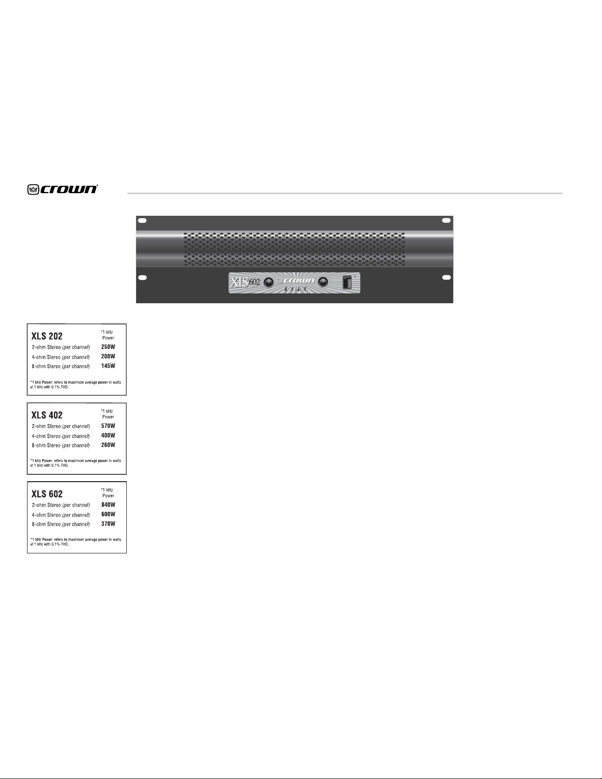
XLS 202
XLS 402
XLS 602
XLS Series Power Amplifi ers
Operation Manual
page 2
1) Read these instructions.
2) Keep these instructions.
3) Heed all warnings.
4) Follow all instructions.
5) Do not use this apparatus near water.
6) Clean only with a dry cloth.
7) Do not block any ventilation openings.
Install in accordance with the manufacturer’s instructions.
8) Do not install near any heat sources such
as radiators, heat registers, stoves, or
other apparatus that produce heat.
9) Do not defeat the safety purpose of
the polarized or grounding-type plug. A
polarized plug has two blades with one
wider than the other. A grounding-type
plug has two blades and a third grounding prong. The wide blade or the third
prong is provided for your safety. If the
provided plug does not fi t into your
outlet, consult an electrician for replacement of the obsolete outlet.
10) Protect the power cord from being walked
on or pinched, particularly at plugs, convenience receptacles, and the point where
they exit from the apparatus.
11) Only use attachments/accessories specifi ed by the manufacturer.
Important Safety
Instructions
MAGNETIC FIELD
CAUTION! Do not locate sensitive high-gain
equipment such as preamplifi ers or tape decks
directly above or below the unit. Because this
amplifi er has a high power density, it has a
strong magnetic fi eld which can induce hum into
unshielded devices that are located nearby. The
fi eld is strongest just above and below the unit.
If an equipment rack is used, we recommend
locating the amplifi er(s) in the bottom of the rack
and the preamplifi er or other sensitive equipment
at the top.
The lightning bolt triangle is used to alert the user
to the risk of electric shock.
The exclamation point triangle is used to alert
the user to important operating or maintenance
instructions.
WATCH FOR THESE SYMBOLS:
IMPORTANT
The XLS Series amplifi ers require Class 2 output
wiring.
TO PREVENT ELECTRIC SHOCK DO NOT REMOVE
TOP OR BOTTOM COVERS. NO USER SERVICEABLE PARTS INSIDE. REFER SERVICING TO
QUALIFIED SERVICE PERSONNEL.
12) Use only with a cart, stand, bracket, or
table specifi ed by the manufacturer, or
sold with the apparatus. When a cart is
used, use caution when moving the cart/
apparatus combination to avoid injury
from tip-over.
13) Unplug this apparatus during lightning
storms or when unused for long periods
of time.
14) Refer all servicing to qualifi ed service
personnel. Servicing is required when
the apparatus has been damaged in any
way, such as power-supply cord or plug
is damaged, liquid has been spilled or
objects have fallen into the apparatus, the
apparatus has been exposed to rain or
moisture, does not operate normally, or
has been dropped.
15) To reduce the risk of fi re or electric shock,
do not expose this apparatus to rain or
moisture.
À PRÉVENIR LE CHOC ÉLECTRIQUE N ENLEVEZ
PAS LES COUVERCLES. IL N’Y A PAS DES PARTIES SERVICEABLE À L’INTÉRIEUR. TOUS REPARATIONS DOIT ETRE FAIRE PAR PERSONNEL
QUALIFIÉ SEULMENT.

XLS Series Power Amplifi ers
Operation Manual
page 3
Table of Contents
Important Safety Instructions ...................................................... 2
1 Welcome ...................................................................................... 4
1.1 Features......................................................................... 4
1.2 Unpacking Your Amplifi er .......................................... 4
2 How to Use This Manual........................................................... 4
3 Setup............................................................................................. 5
3.1 Unpack Your Amplifi er ................................................ 5
3.2 Voltage Selection ........................................................ 5
3.3 Mount Your Amplifi er .................................................. 5
3.4 Ensure Proper Cooling................................................ 5
3.5 Choose Input Wire and Connectors ......................... 6
3.6 Choose Output Wire and Connectors....................... 6
3.7 Wire Your System........................................................ 7
3.7.1 Stereo Mode...................................................... 7
3.7.2 Bridge-Mono Mode .......................................... 7
3.8 Connect to AC Mains................................................... 8
3.9 Startup Procedure........................................................ 8
4 Operation ..................................................................................... 8
4.1 Precautions.................................................................... 8
4.2 Front Panel Controls and Indicators........................ 9
4.3 Back Panel Controls and Connectors .................... 10
5 Advanced Features and Options............................................ 11
5.1 Protection Systems ................................................... 11
5.1.1 Anti-Clip Limiters........................................... 11
5.1.2 High-Pass Filters............................................ 11
5.1.3 Output Current Limiting ................................11
5.1.4 DC Protection .................................................. 11
5.1.5 Fuse .................................................................. 11
5.1.6 Thermal Protection ........................................ 11
6 Troubleshooting........................................................................ 12
7 Specifi cations............................................................................ 13
8 Service........................................................................................ 15
8.1 Worldwide Service.................................................... 15
8.2 US and Canada Service............................................ 15
8.2.1 Factory Service .............................................. 15
9 Warranty..................................................................................... 16
Factory Service Information Form ............................................ 19
XLS Series Power Amplifi ers
Operation Manual
page 4
The XLS Series of power amplifi ers from
Crown represents a new era in affordable,
quality power amplifi cation. The line consists
of three models in a uniform, rugged
chassis, incorporating the best of tried-andtrue design principles and innovative features.
Modern power amplifi ers are sophisticated
pieces of engineering capable of producing
extremely high power levels. They must be
treated with respect and correctly installed if
they are to provide the many years of reliable
service for which they were designed.
In addition, XLS Series amplifi ers include a
number of features which require some explanation before they can be used to their maximum advantage.
Please take the time to study this manual so
that you can obtain the best possible service
from your amplifi er.
1.1 Features
• Simple, reliable design incorporates many
popular features.
• Selectable high-pass fi lter on each channel
enables amplifi er to work more effi ciently
when full band-width is not required (eg:
two- or three-way systems).
1 Welcome
2 How to Use This
Manual
This manual provides you with the necessary
information to safely and correctly setup and
operate your amplifi er. It does not cover
every aspect of installation, setup or operation
that might occur under every condition. For
additional information, please consult Crown’s
Amplifi er Application Guide (available online at
www.crownaudio.com), Crown Tech Support,
your system installer or retailer.
We strongly recommend you read all instructions, warnings and cautions contained in this
manual. Also, for your protection, please send
in your warranty registration card today. And
save your bill of sale—it’s your offi cial proof
of purchase.
• Pair of linear optocoupler clip limiters protects loudspeakers from being overdriven.
• Housed in a rugged, all-steel 3U chassis.
• Effi cient forced-air fan prevents excessive
thermal buildup.
• Electronically balanced XLR inputs and
touch-proof binding post outputs.
• Features precision detented level controls,
power switch, and four LEDs, which indicate clip for each channel, power and fault
conditions.
1.2 Unpacking Your Amplifi er
Please unpack and inspect your amplifi er for
any damage that may have occurred during
transit. If damage is found, notify the transportation company immediately. Only you can
initiate a claim for shipping damage. Crown
will be happy to help as needed. Save the
shipping carton as evidence of damage for the
shipper’s inspection.
We also recommend that you save all packing
materials so you will have them if you ever
need to transport the unit. Never ship the
unit without the factory pack.
XLS Series Power Amplifi ers
Operation Manual
page 5
3 Setup
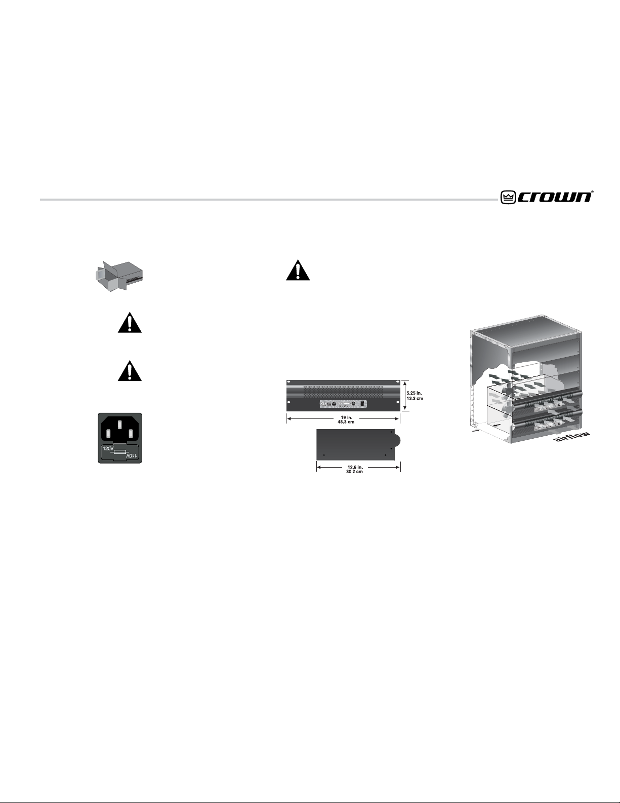
Figure 3.3 Airfl ow
Figure 3.2 Dimensions
3.4 Ensure Proper Cooling
When using an equipment rack, mount units
directly on top of each other. Close any open
spaces in rack with blank panels. DO NOT
block side or front air vents.
Figure 3.3 illustrates standard amplifier airflow.
3.1 Unpack Your Amplifi er
YOU WILL NEED (not supplied):
• Two input wiring cables
• Two output wiring cables
• Rack for mounting amplifi er (or a stable
surface for stacking)
WARNING: Before you start to set up
your amplifi er, make sure you read and
observe the Important Safety Instructions found at the beginning of this
manual.
3.2 Voltage Selection
CAUTION: Before use, your amplifi er
must be set to the correct operating
voltage for your local supply. Typically,
units are shipped from the factory with voltage
already set with the correct setting, but this
setting should be verifi ed before fi rst using the
amplifi er.
The selected voltage is displayed on the top,
left side of the fuse drawer (see Figure 3.1). To
change the voltage setting; disconnect the power
source, then gently pry out the fuse casing from
the fuse drawer. Replace with the correct voltage
positioned to display on the top left side.
Be sure to operate your amplifi er from a power
supply within ±10% of the rated voltage (i.e.,
108-132V for 120V supply).
Figure 3.1
Voltage Selection
2 in.
3.3 Mount Your Amplifi er
CAUTION: Before you begin, make sure
your amplifi er is disconnected from the
power source, with power switch in the
“off” position and all level controls
turned completely down (counterclockwise).
Use a standard 19-inch (48.3 cm) equipment
rack. See Figure 3.2 for amplifi er dimensions.
You may also stack amps without using a
cabinet.
NOTE: When transporting, amplifi ers should be
supported at both front and back.
XLS Series Power Amplifi ers
Operation Manual
page 6
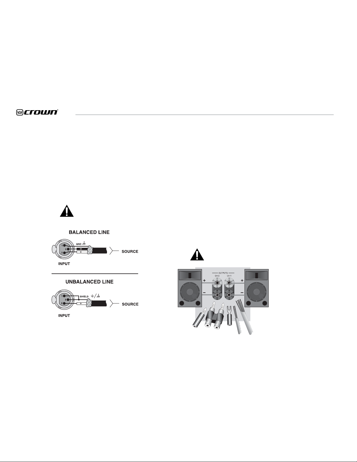
Figure 3.4. Input Connector Wiring
3 Setup
3.5 Choose Input Wire
and Connectors
Crown recommends using pre-built or professionally wired, balanced line (two-conductor
plus shield), 22-24 gauge cables and connectors. You should use 3-pin male XLR cable
ends at the amplifi er inputs. Unbalanced line
may also be used but may result in noise over
long cable runs.
Note: Male XLR signal links are also provided
on the amplifi er to allow daisy-chaining of the
audio signal.
Refer to Figure 3.4 for correct XLR connector
pin assignments.
NOTE: Custom wiring should only be
performed by qualifi ed personnel.
Figure 3.5. Output Connector Wiring
3.6 Choose Output Wire
and Connectors
Crown recommends using pre-built or professionally wired, high-quality, two- or fourconductor, heavy gauge speaker wire and
connectors. You may use banana plugs, spade
lugs or bare wire for your output connectors
(see Figure 3.5). To prevent the possibility
of short-circuits, wrap or otherwise insulate
exposed loudspeaker cable connectors.
Using the guidelines below, select the appropriate size of wire based on the distance from
amplifi er to speaker.
Distance Wire Size
up to 25 ft. 16 gauge
26-40 ft. 14 gauge
41-60 ft. 12 gauge
61-100 ft. 10 gauge
101-150 ft. 8 gauge
151-250 ft. 6 gauge
CAUTION: Never use shielded cable for
output wiring.
 Loading...