


CSL SERIES
POWER |
OFF |
POWER |
OFF |
MODEL 800–CSL |
11.5 AMPS |
AC VOLTS 120 |
60 Hz |
MAXIMUM OUTPUT: 230 WATTS
PER CHANNEL INTO 4 OHMS AT 1 KHz WITH NO MORE THAN 0.1% THD
® |
INTERNATIONAL, INC. |
ELECTRONIC EQUIPMENT |
|
ELKHART, IN 46517 |
0000 |
MADE IN U.S.A. |
|
SERIAL NUMBER |
000000 |
WARNING: TO
REDUCE THE RISK OF FIRE OR ELECTRIC SHOCK, DO NOT EXPOSE
THIS EQUIPMENT TO
RAIN OR MOISTURE. REG. U.S. PAT. OFF. 3,808,545
4,330,809
4,611,180
|
|
CAUTION: TO PREVENT ELECTRIC |
|
|
SHOCK DO NOT REMOVE TOP OR BOTTOM |
|
OUTPUTS |
COVERS. NO USER SERVICEABLE PARTS |
CAUTION: |
INSIDE. REFER SERVICING TO QUALIFIED |
|
CLASS 2 |
SERVICE PERSONNEL. DISCONNECT POWER |
|
THIS COVER IS NECESSARY FOR |
CORD BEFORE REMOVING REAR P.I.P. |
|
EFFICIENT COOLING OF THE AMPLIFIER. |
OUTPUT |
MODULE TO ACCESS SENSITIVITY SWITCH. |
WIRING |
ATTENTION: DÉBRANCHER AVANT |
|
REMOVE ONLY TO ACCESS GAIN SWITCH. |
REQUIRED. |
|
|
|
D'OUVRIR. |
CH-2 CH-1
|
|
|
|
|
|
|
CH-2 |
|
|
CH-1 |
|
|
|
|
BRIDGE-MONO WIRING |
– |
PARALLEL-MONO WIRING |
+ |
||
|
|
|
|
|
|
|
|
|
|
|
|
|
1 |
TURN AMPLIFIER OFF. |
1 |
TURN AMPLIFIER OFF. |
||||
|
|
|
|
|
6 |
|
|
|
6 |
|
|
|
|
|
||||||
|
|
|
|
5 |
7 |
|
|
|
5 |
7 |
|
|
2 |
SET STEREO/MONO |
+ |
2 |
SET STEREO/MONO SWITCH |
– |
||
|
STEREO |
|
|
4 |
|
|
8 |
|
|
4 |
|
8 |
|
|
|
SWITCH TO |
|
TO PARALLEL-MONO. |
||
PARALLEL |
BRIDGE |
BALANCED |
3 |
|
|
9 |
|
|
3 |
|
9 |
UNBALANCED |
|
BRIDGE-MONO. |
|
3 |
ADD JUMPER (14 |
|
||
2 |
|
|
10 |
INPUT GROUND LIFT |
|
2 |
|
10 |
3 |
OUTPUT ACROSS |
|
|
GAGE OR LARGER) |
|
||||||
MONO |
MONO |
INPUT WIRING |
1 |
|
|
11 |
|
|
1 |
|
11 |
INPUT WIRING |
|
RED TERMINALS |
|
|
ACROSS RED TERMINALS. |
|
||
|
|
|
+ TIP |
0 |
|
12 |
INPUT |
LIFT |
INPUT |
0 |
|
12 |
|
+ TIP |
|
ONLY. (CH-1 |
|
4 |
OUTPUT ACROSS CH-1 |
|
CAUTION: TURN OFF AMPLIFIER |
|
GAIN |
GAIN |
|
|
IS POSITIVE.) |
|
|
||||||||||||
|
– RING |
|
(AFFECTS PHONE INPUTS ONLY.) |
(MONO) |
|
|
|
|
|
|
TERMINALS ONLY. |
|
||||||||
BEFORE CHANGING THIS SWITCH! |
GND |
SLEEVE |
|
|
|
|
|
|
|
GND |
SLEEVE |
|
|
|
|
|
|
|||
Models: 460, 800, 1400 CSL®
Some models may be exported under the name Amcron.®
© 1997 by Crown International, Inc., P.O. Box 1000, Elkhart, IN 46515-1000 U.S.A. Telephone: 219-294- 8000. Fax: 219-294-8329. CSL series amplifiers are produced by the Professional Audio Division of Crown International, Inc. Trademark Notice: Amcron,® Crown,® CSL®, and ODEP ® are registered trademarks of Crown International, Inc. Other trademarks are the property of their respective owners.
|
|
Approved for |
120 VAC North |
|
Commercial |
|
|
|
|||
|
|
|
|||
|
|
THX® Theatre |
|
||
|
|
American |
|
Audio |
|
|
|
Systems |
|
||
|
|
Units Only: |
® |
E106377 |
|
|
|
|
|||
|
|
|
|
|
|
|
|
|
|
|
|
125168-1
8/97

 3
3 
 YEAR
YEAR 
THREE YEAR
FULL WARRANTY
 3
3 
 YEAR
YEAR 
WORLDWIDE |
NORTH AMERICA |
SUMMARY OF WARRANTY
The Crown Audio Division of Crown International, Inc., 1718 West Mishawaka Road, Elkhart, Indiana 46517-4095 U.S.A. warrants to you, the ORIGINAL PURCHASER and ANY SUBSEQUENT OWNER of each NEW Crown1 product, for a period of three (3) years from the date of purchase by the original purchaser (the “warranty period”) that the new Crown product is free of defects in materials and workmanship, and we further warrant the new Crown product regardless of the reason for failure, except as excluded in this Crown Warranty.
1 Note: If your unit bears the name “Amcron,” please substitute it for the name “Crown” in this warranty.
ITEMS EXCLUDED FROM THIS CROWN WARRANTY
This Crown Warranty is in effect only for failure of a new Crown product which occurred within the Warranty Period. It does not cover any product which has been damaged because of any intentional misuse, accident, negligence, or loss which is covered under any of your insurance contracts. This Crown Warranty also does not extend to the new Crown product if the serial number has been defaced, altered, or removed.
WHAT THE WARRANTOR WILL DO
We will remedy any defect, regardless of the reason for failure (except as excluded), by repair, replacement, or refund. We may not elect refund unless you agree, or unless we are unable to provide replacement, and repair is not practical or cannot be timely made. If a refund is elected, then you must make the defective or malfunctioning product available to us free and clear of all liens or other encumbrances. The refund will be equal to the actual purchase price, not including interest, insurance, closing costs, and other finance charges less a reasonable depreciation on the product from the date of original purchase. Warranty work can only be performed at our authorized service centers. We will remedy the defect and ship the product from the service center within a reasonable time after receipt of the defective product at our authorized service center.
HOW TO OBTAIN WARRANTY SERVICE
You must notify us of your need for warranty service not later than ninety (90) days after expiration of the warranty period. All components must be shipped in a factory pack. Corrective action will be taken within a reasonable time of the date of receipt of the defective product by our authorized service center. If the repairs made by our authorized service center are not satisfactory, notify our authorized service center immediately.
DISCLAIMER OF CONSEQUENTIAL AND INCIDENTAL DAMAGES
YOU ARE NOT ENTITLED TO RECOVER FROM US ANY INCIDENTAL DAMAGES RESULTING FROM ANY DEFECT IN THE NEW CROWN PRODUCT. THIS INCLUDES ANY DAMAGE TO ANOTHER PRODUCT OR PRODUCTS RESULTING FROM SUCH A DEFECT.
WARRANTY ALTERATIONS
No person has the authority to enlarge, amend, or modify this Crown Warranty. This Crown Warranty is not extended by the length of time which you are deprived of the use of the new Crown product. Repairs and replacement parts provided under the terms of this Crown Warranty shall carry only the unexpired portion of this Crown Warranty.
DESIGN CHANGES
We reserve the right to change the design of any product from time to time without notice and with no obligation to make corresponding changes in products previously manufactured.
LEGAL REMEDIES OF PURCHASER
No action to enforce this Crown Warranty shall be commenced later than ninety (90) days after expiration of the warranty period.
THIS STATEMENT OF WARRANTY SUPERSEDES ANY OTHERS CONTAINED IN THIS MANUAL FOR CROWN PRODUCTS.
9/90
Telephone: 219-294-8200. Facsimile: 219-294-8301
SUMMARY OF WARRANTY
The Crown Audio Division of Crown International, Inc., 1718 West Mishawaka Road, Elkhart, Indiana 46517-4095 U.S.A. warrants to you, the ORIGINAL PURCHASER and ANY SUBSEQUENT OWNER of each NEW Crown product, for a period of three (3) years from the date of purchase by the original purchaser (the “warranty period”) that the new Crown product is free of defects in materials and workmanship. We further warrant the new Crown product regardless of the reason for failure, except as excluded in this Warranty.
ITEMS EXCLUDED FROM THIS CROWN WARRANTY
This Crown Warranty is in effect only for failure of a new Crown product which occurred within the Warranty Period. It does not cover any product which has been damaged because of any intentional misuse, accident, negligence, or loss which is covered under any of your insurance contracts. This Crown Warranty also does not extend to the new Crown product if the serial number has been defaced, altered, or removed.
WHAT THE WARRANTOR WILL DO
We will remedy any defect, regardless of the reason for failure (except as excluded), by repair, replacement, or refund. We may not elect refund unless you agree, or unless we are unable to provide replacement, and repair is not practical or cannot be timely made. If a refund is elected, then you must make the defective or malfunctioning product available to us free and clear of all liens or other encumbrances. The refund will be equal to the actual purchase price, not including interest, insurance, closing costs, and other finance charges less a reasonable depreciation on the product from the date of original purchase. Warranty work can only be performed at our authorized service centers or at the factory. We will remedy the defect and ship the product from the service center or our factory within a reasonable time after receipt of the defective product at our authorized service center or our factory. All expenses in remedying the defect, including surface shipping costs in the United States, will be borne by us. (You must bear the expense of shipping the product between any foreign country and the port of entry in the United States and all taxes, duties, and other customs fees for such foreign shipments.)
HOW TO OBTAIN WARRANTY SERVICE
You must notify us of your need for warranty service not later than ninety (90) days after expiration of the warranty period. All components must be shipped in a factory pack, which, if needed, may be obtained from us free of charge. Corrective action will be taken within a reasonable time of the date of receipt of the defective product by us or our authorized service center. If the repairs made by us or our authorized service center are not satisfactory, notify us or our authorized service center immediately.
DISCLAIMER OF CONSEQUENTIAL AND INCIDENTAL DAMAGES
YOU ARE NOT ENTITLED TO RECOVER FROM US ANY INCIDENTAL DAMAGES RESULTING FROM ANY DEFECT IN THE NEW CROWN PRODUCT. THIS INCLUDES ANY DAMAGE TO ANOTHER PRODUCT OR PRODUCTS RESULTING FROM SUCH A DEFECT. SOME STATES DO NOT
ALLOW THE EXCLUSION OR LIMITATIONS OF INCIDENTAL OR CONSEQUENTIAL DAMAGES, SO THE ABOVE LIMITATION OR EXCLUSION MAY NOT APPLY TO YOU.
WARRANTY ALTERATIONS
No person has the authority to enlarge, amend, or modify this Crown Warranty. This Crown Warranty is not extended by the length of time which you are deprived of the use of the new Crown product. Repairs and replacement parts provided under the terms of this Crown Warranty shall carry only the unexpired portion of this Crown Warranty.
DESIGN CHANGES
We reserve the right to change the design of any product from time to time without notice and with no obligation to make corresponding changes in products previously manufactured.
LEGAL REMEDIES OF PURCHASER
THIS CROWN WARRANTY GIVES YOU SPECIFIC LEGAL RIGHTS, YOU MAY ALSO HAVE OTHER RIGHTS WHICH VARY FROM STATE TO STATE. No action to enforce this Crown Warranty shall be commenced later than ninety (90) days after expiration of the warranty period.
THIS STATEMENT OF WARRANTY SUPERSEDES ANY OTHERS CONTAINED IN THIS MANUAL FOR CROWN PRODUCTS.
Telephone: 219-294-8200. Facsimile: 219-294-8301 |
9/90 |
The information furnished in this manual does not include all of the details of design, production, or variations of the equipment. Nor does it cover every possible situation which may arise during installation, operation or maintenance. If your unit bears the name “Amcron,” please substitute it for the name “Crown” in this manual. If you need special assistance beyond the scope of this manual, please contact our Technical Support Group.
Crown Audio Division Technical Support Group
Plant 2 SW, 1718 W. Mishawaka Rd., Elkhart, Indiana 46517 U.S.A.
Phone: 800-342-6939 (North America, Puerto Rico and Virgin Islands) or 219-294-8200 Fax: 219-294-8301 Fax Back (North America only): 800-294-4094 or 219-293-9200 Fax Back (International): 219-294-8100 Internet: http://www.crownintl.com
|
|
|
|
|
|
|
|
|
|
|
|
|
|
|
|
|
|
C A U T I O N |
|
|
A V I S |
|
|
|
|
|
|
|
|
|
|
|
|
RISK OF ELECTRIC SHOCK |
|
|
RISQUE DE CHOC ÉLECTRIQUE |
|
|
|
|
DO NOT OPEN |
|
|
N’OUVREZ PAS |
|
|
|
TO PREVENT ELECTRIC SHOCK DO |
À PRÉVENIR LE CHOC ÉLECTRIQUE |
|
||||
|
NOT REMOVE TOP OR BOTTOM |
N’ENLEVEZ PAS LES COUVERCLES. IL |
|
||||
|
COVERS. NO USER SERVICEABLE |
N’Y A PAS DES PARTIES SERVICEABLE |
|
||||
|
PARTS INSIDE. REFER SERVICING |
À L’INTÉRIEUR. TOUS REPARATIONS |
|
||||
|
TO QUALIFIED SERVICE PERSON- |
DOIT ETRE FAIRE PAR PERSONNEL |
|
||||
|
NEL. DISCONNECT POWER CORD |
QUALIFIÉ SEULMENT. DÉBRANCHER |
|
||||
|
BEFORE REMOVING BACK PANEL |
LA BORNE AVANT D’ENLEVER LA |
|
||||
|
COVER TO ACCESS GAIN SWITCH. |
COVERTURE EN ARRIÈRE. |
|
||||
|
|
|
|
|
|
|
|
|
|
|
|
|
|
|
|
WARNING
TO REDUCE THE RISK OF ELECTRIC SHOCK, DO NOT EXPOSE THIS EQUIPMENT TO RAIN OR MOISTURE!
Magnetic Field
CAUTION! Do not locate sensitive high-gain equipment such as preamplifiers or tape decks directly above or below the unit. Because this amplifier has a high power density, it has a strong magnetic field which can induce hum into unshielded devices that are located nearby. The field is strongest just above and below the unit.
If an equipment rack is used, we recommend locating the amplifier(s) in the bottom of the rack and the preamplifier or other sensitive equipment at the top.
The lightning bolt triangle is used to alert the user to the risk of electric shock.
The exclamation point triangle is used to alert the user to important operating or maintenance instructions.
Printed on recycled paper.

CSL Series Power Amplifiers
|
|
|
CONTENTS |
|
1 |
Welcome ....................................................................... |
|
5 |
|
|
1.1 |
Unpacking ............................................................. |
5 |
|
|
1.2 |
Features ................................................................ |
5 |
|
2 |
Installation |
.................................................................... |
6 |
|
|
2.1 |
Stereo |
.................................................................... |
6 |
|
2.2 |
Mono ..................................................................... |
|
6 |
|
2.3 |
Input Sensitivity Adjustment ................................... |
8 |
|
|
2.4 |
Additional Load Protection ..................................... |
8 |
|
3 |
Operation ..................................................................... |
|
9 |
|
|
3.1 |
Precautions ............................................................ |
9 |
|
|
3.2 |
Indicators .............................................................. |
9 |
|
|
3.3 |
Protection Systems ................................................ |
9 |
|
|
|
3.3.1 |
ODEP .......................................................... |
9 |
|
|
3.3.2 Ultrasonic and RF Protection ....................... |
9 |
|
|
|
3.3.3 |
Drive Protection ........................................... |
9 |
|
|
3.3.4 |
Transformer Thermal Protection ................... |
9 |
|
|
3.3.5 Fuses and Circuit Breakers ........................ |
10 |
|
|
3.4 |
Controls ............................................................... |
10 |
|
|
3.5 |
Filter Cleaning ...................................................... |
10 |
|
4 |
Specifications ............................................................ |
11 |
||
5 |
Accessories ............................................................... |
17 |
||
|
5.1 |
MT-XLR ................................................................ |
17 |
|
|
5.2 |
MT-BB |
.................................................................. |
17 |
6 |
Service ....................................................................... |
|
18 |
|
|
6.1 |
Worldwide Service ............................................... |
18 |
|
|
6.2 |
North American Service ....................................... |
18 |
|
|
|
6.2.1 Service at a N. American Service Center ... |
18 |
|
|
|
6.2.2 |
Factory Service ......................................... |
18 |
Page 4

CSL Series Power Amplifiers
POWER |
OFF |
Removable Grille |
|
Enable |
Enable |
||
and Dust Filter |
|
Indicator |
Switch |
||
|
|
|
|
|
|
|
|
|
|
|
|
|
|
|
|
|
|
Fig. 1.1 1400 CSL Front and Back Panels
1 Welcome
Congratulations on your purchase of a Crown® CSL® amplifier. CSL amplifiers are compact, professional stereo power amplifiers engineered to meet the most demanding sound reinforcement needs. They compare very favorably to more expensive amplifiers, providing uncolored sound and signal-to-noise ratios more commonly associated with recording studios.
This manual will help you successfully install and use your amplifier—we strongly recommend you read all instructions, warnings and cautions. If you plan to operate in one of the two mono modes, be sure to read the Mono section. Also for your protection, please save your bill of sale as it is your official proof of purchase.
1.1 Unpacking
Please unpack and inspect your new amplifier for any damage that may have occurred during transit. If damage is found, notify the transportation company immediately. Only you may initiate a claim with the carrier for damage resulting during shipment. Even if the unit arrived in perfect condition, as most do, save all packing materials so you will have them if you ever need to transport the unit. NEVER SHIP THE UNIT WITHOUT THE FACTORY PACK.
1.2 Features
Rugged, professional power amplifier mounts in a standard 19 inch (48.3 cm) equipment rack.
Front panel power switch with turn-on delay for loudspeaker protection.
Full, uncolored power with any reasonable load.
Patented Output Device Emulation Protection (ODEP ®) keeps the amplifier working when others would fail.
High damping factor provides superior control over lowfrequency drivers for a clean, accurate low end.
Safe with any load. Bridge-Mono and Parallel-Mono modes offer optimal load-matching performance.
Complete protection against shorted outputs, mismatched loads, overheating, DC input/output and highfrequency overload; full internal fault protection.
Balanced phone jack inputs with internal three-posi- tion sensitivity switch. Optional XLR or barrier block input connectors are available with the MT-XLR and MT-BB accessories.
Ground lift switch helps prevent “ground loops” by isolating the chassis from the phone input grounds.
Efficient heat sinks and self-contained forced air cooling system dissipate heat quickly and evenly for extra amplifier protection and greater power output.
Three year “No-Fault” full warranty and guaranteed specifications protect your investment.
Page 5
CSL Series Power Amplifiers
2 Installation
Always remove power from the unit and turn the level controls off when making connections. This reduces the chance of loudspeaker damage from loud blasts.
Follow the guidelines listed next as well as the steps required for the specific mode of operation:
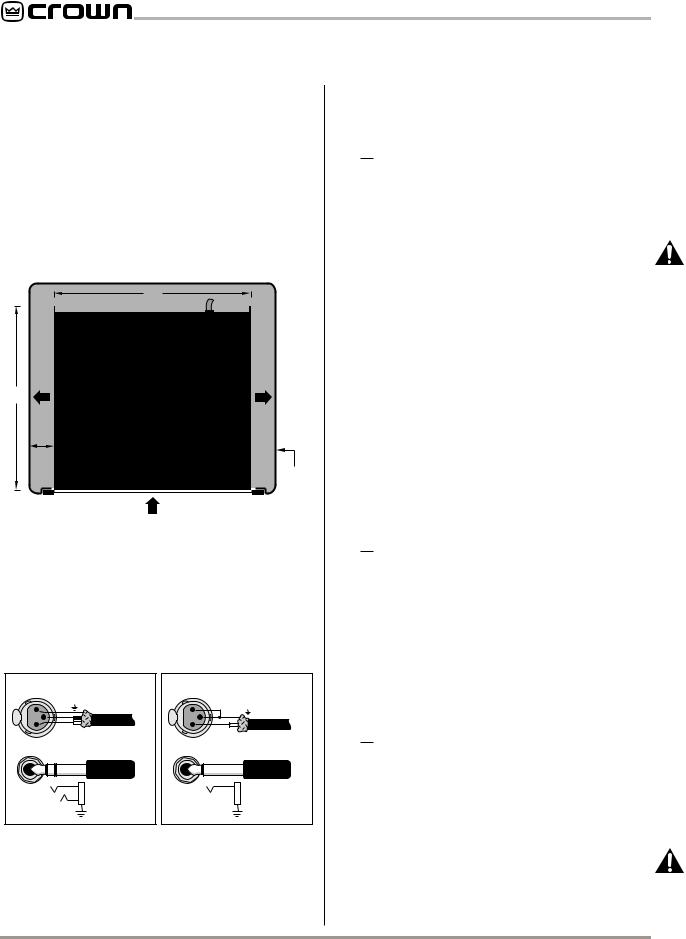
1.Install the amplifier in a standard 19 inch (48.3 cm) rack or place it on a stable surface. The mounting dimensions are 19 inches (48.3 cm) wide, 3.5 inches (8.9 cm) tall and 16 inches (40.6 cm) deep behind the mounting surface. IMPORTANT! Allow for adequate ventilation.
AIR
FLOW
16 in
40.6 cm
2 in MIN.
17 in
43.2 cm
IMPORTANT: Be sure the back of the amplifier is supported.
AIR
FLOW
AMPLIFIER (TOP VIEW)
RACK
CABINET
AIR FLOW
Fig. 2.1 Do NOT Block Air Flow
2.Use high-quality loudspeaker cables to connect the load to the amplifier’s output jacks. Do not use shielded cable. Banana plugs are recommended for this connection.
3.Use shielded cables to connect audio sources to the amplifier inputs. Either balanced or unbalanced wiring can be used as shown below. (XLR connectors are avail-
|
BALANCED |
|
UNBALANCED |
|
1 |
GND |
1 |
SHIELD |
|
– |
|
|||
|
|
|
||
3 |
|
3 |
|
|
2 |
+ |
2 |
+ |
|
|
|
|
||
INPUT |
FROM |
INPUT |
FROM |
|
PREAMPLIFIER |
PREAMPLIFIER |
|||
+ |
|
|
+ |
|
|
– |
|
|
|
SHIELD |
|
SHIELD |
|
|
Fig. 2.2 CSL Input Wiring
able with the MT-XLR accessory. See Section 5.)
4.An appropriate AC cord and plug are provided. Use an isolated wall outlet with the correct voltage and adequate current. Voltages more than 10% over the amplifier’s rated voltage may damage the ±15 volt regu-
lator, filter capacitors and output transistors.
2.1 Stereo
1.Turn the level controls down (fully counterclockwise) and turn off the amplifier.
2.Set the back panel stereo/mono switch to Stereo.
3.If present, remove the Parallel-Mono jumper.
4.Connect the input and output cables as shown in the first example in Figure 2.3.
5.Turn on the amplifier and adjust the level for each channel with the back panel level controls.
CAUTION: In Stereo mode, never parallel the two outputs by directly tying them together, and never parallel them with the output of another amplifier.
2.2 Mono
The monaural operating modes provide twice the power to one channel as the Stereo mode. In BridgeMono mode, the outputs are wired in series for twice the output voltage. In Parallel-Mono mode, the outputs are paralleled for twice the current capacity.
Bridge-Mono mode is provided for loads with an impedance greater than 4 ohms. Parallel-Mono mode should be used with loads of 4 ohms or less.
B R I D G E - M O N O
1.Turn the level controls down (fully counterclockwise) and turn off the amplifier.
2.Set the back panel stereo/mono switch to Bridge-Mono.
3.If present, remove the Parallel-Mono jumper.
4.Connect the input and output cables as shown in the second example in Figure 2.3. Use the Ch.1 input only.
5.Make sure the load is balanced (neither side shorted to ground) and do not use the black (–) banana jacks.
6.Turn on the amplifier and adjust the level. Use the Ch.1 level control only.
P A R A L L E L - M O N O
1.Turn down the level controls (fully counterclockwise) and turn off the amplifier.
2.Set the back panel stereo/mono switch to Parallel-Mono.
3.Install a solid jumper (at least 14 gauge) across the output between the two red (+) banana jacks.
4.Connect the input and output cables as shown in the third example in Figure 2.3. Use the Ch.1 input only.
5.Turn on the amplifier and adjust the level. Use the Ch.1 level control only.
CAUTION: When wired for Parallel-Mono mode, do not attempt to operate the amplifier in Stereo or Bridge-Mono mode until the output jumper is removed. Failure to do so will result in inefficient op-
Page 6
 Loading...