

Page 1
ALUMINIUM HIKING POLES
ALUMINIUM HIKING POLES
Instructions for use
ALUMINIOWE KIJKI DO TREKKINGU
Instrukcja obsługi
ALUMINIJASTE POHODNE PALICE
Navodilo za uporabo
ALUMINIUM-TREKKINGSTÖCKE
Bedienungsanleitung
IAN 103778
11
Page 2
Congratulations on purchasing this high-quality product. Be sure
to familiarise yourself with the assembly instructions prior to use.
Please take the time to carefully read through the following assembly
instructions and safety notes. Only use the product as described and for
the intended use. Please retain these instructions for future reference and
ensure that they are passed on to any third party.
Use
This hiking pole is equipped with a hardened metal tip and is intended
for hiking in the countryside, on ice or on other smooth surfaces.
It is also equipped with an asphalt pad which can be attached and
removed easily when hiking on asphalt or other hard surfaces.
Parts List
(1) Strap adjustment system
A
10
9
8
7
1
(2) Wrist strap
2
(3) Asphalt pad
(4) Combo bracket
3
4
(5) Height adjustment system
(6) Hollow ground tip
(7) Hiking pole
(8) Basket
(9) Clip for connecting the poles
(10) Ergonomic 2 component handle
5
Technical data
Length: adjustable 66 - 135cm
Weight: one trekking pole approx. 278g
Maximum weight: 140kg
Material: aluminium
6
Safety notice
• Do not attempt any repairs that might put your safety at risk.
• We recommend using a heart rate monitor.
• Consult your doctor before engaging in sports activities if you have a
known cardiovascular problem.
• Use sports shoes with treaded soles and supportive sides.
• Avoid sporting activities in the dark or use reflectors worn on the body
at dusk.
• Check the screws on the hiking pole before use.
• Check the hiking pole for damage before use.
• As soon as you ascertain any damage in the pole segments, or
anything faulty that will affect the function of the hiking pole,
cease use of the pole immediately.
• If possible, avoid public roads in order to minimise risk of accidents.
• Hiking poles are not suitable for downhill skiing.
• Please do not use oil as all types of oil can negatively influence the
retention force of the adjustment mechanism.
• Remember that the tip of the hiking pole may damage floors.
• Do not sit on the pole as it could break.
• Pointed poles are dangerous for children.
• This equipment is solely intended for private use.
This equipment is not guaranteed for commercial use.
• During use, please check the locking system regularly.
2
GB
Page 3
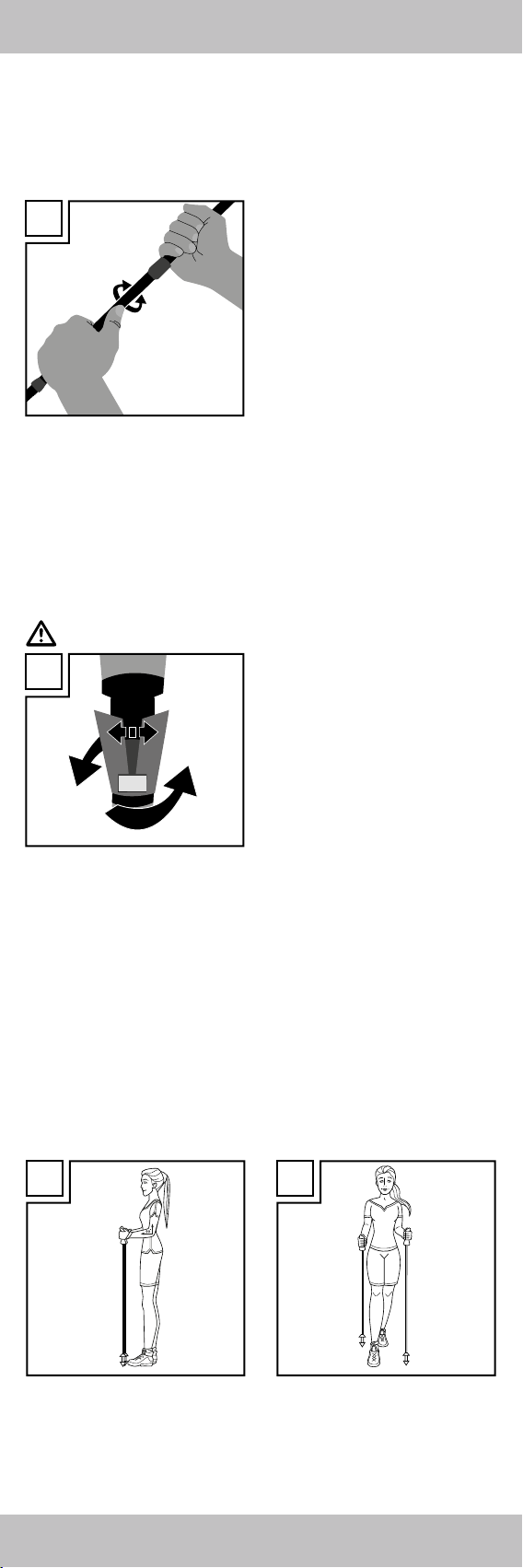
Adjusting the pole length
Your trekking poles are height adjustable from 66 - 135cm and should
be adjusted to your height and the type of use.
Locking/opening (Fig. B)
B
Opening
Locking
The direction for opening and
locking is already indicated at the
top of the trekking pole. Hold the
upper section of the pole with one
hand, you will then be able to
tighten the lower pole sections
turning clockwise, or lock it turning
counter-clockwise. Keep tightening
the screw connection until you’re
unable to turn it any more by typical
force.
Enabling/disabling the damping system
To disable the damping system, secure the pole length as described
under “Adjusting the pole length”.
Then slightly turn the centre section of the trekking pole against the
locking direction. You will now hear a distinct click. The damping system
is now disabled. Turn the centre section slightly in the locking direction to
reactivate the damping system.
Note:
C
damage the damping system.
• If the pole won’t close, remove the respective pole section from the
pole. Turn the locking system 2 - 3 turns by hand until the orange
clamping device begins to slightly spread (see Fig. C). Then reinsert the
individual pole section into the pole and secure to the desired length.
• Walking on level surfaces (Fig. D/E)
Adjust the pole length so your upper arm and forearm are at a 90° angle. Be sure to adjust the poles to the same length. The centre and bottom
stock sections have pole length marks. To adjust the pole to a length of
120cm, secure the centre and bottom pole sections so the 120cm
marking are just visible in the upper pole section.
• After closing check if the fasteners
are secure by slightly leaning onto
the pole.
• Never fasten the pole length
beyond the “STOP” mark!
• When pulled very tightly the
trekking pole locking system with
attain a clamping force of approx.
140kg.
• Loads over 100kg with the
damping system disabled may
D E
3GB
Page 4

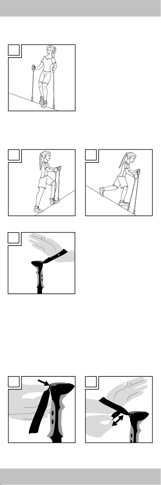
• Walking traverses (Fig. F)
Here the upper pole must be shortened and the low pole extended so
both pieces can provide support.
F
• Climbing (Fig. G/H)
Ascending the poles must be shortened to present a comfortable support.
Descending the poles must be extended so you are in a comfortable
upright position whilst supported.
G H
Using the strap (Fig. I)
I
Attach the strap so the back of your
hand is enclosed by the top section
of the strap.
The Rocktrail logo will be facing
outward. Now hold the grip. Please
note the wrist straps are marked “L”
and “R”!
Adjusting the wrist strap (Fig. J-M)
The size of the wrist strap can be adjusted using the push button. To open
the locking mechanism, press the push button on the strap adjustment
system with your thumb (Fig. J).
The strap is now unlocked and can be adjusted to the correct fit. Pull the
open, bottom strap end to tighten the strap. Pull in the opposite direction
to loosen the strap (Fig. K).
Tighten the strap by holding the pole with one hand, and with the other
pull the upper loop to lock in the push button (Fig. L).
Adjust the size of the loop so it doesn’t cut when wrapping your hand
around the grip (Fig. M).
J K
4 GB
Page 5

L M
Helpful hints for use
• Wear gloves in cold weather.
• Be sure to take sufficient liquids on extended outings (if necessary use a
hydration belt or hydration pack).
• Dress appropriate for the weather.
Combo bracket for asphalt pad & basket
Use the combo bracket to store the asphalt pad and the trekking pole
basket. The asphalt pad is used on rocky and hard surfaces, and the
trekking pole basket for soft surfaces to prevent the trekking pole from sinking in. You may also remove the combo bracket. Pull the tab of the red
rubber ring to remove it from the bracket guide. The bracket may now be
removed from the pole. To attach the combo bracket place it on the pole,
wrap the rubber band once around the pole and reinsert in the guide on
the combo holder. When not using the asphalt pads or the trekking pole
basket for your current route you can attach/insert them in the basket
interchanging system holder.
Warming up and stretching
You should properly warm up and stretch before trekking (see Fig. N-Q).
• Fig. N: Front thigh muscles
Draw your foot toward your bum.
• Fig. O: Rear lower leg muscles
Press your heel into the floor and lean your body slightly forward.
• Fig. P: Inside hip muscles
Slide your pelvis downward at an angle.
• Fig. Q: Calf muscles
Raise and lower your heels several times.
N O
P Q
GB
5
Page 6

Care and cleaning
Clean the hiking poles with a cloth soaked in lukewarm or soapy water.
Do not attempt to clean the poles using detergent or abrasive cleaning
agents. These may permanently damage the plastic parts and printed
marks.
Storage and transport
Do not leave the hiking poles exposed to direct sunlight or excessive
temperatures as this could cause cracks to appear, causing them to
disintegrate, reducing their lifespan and drastically reducing their use.
Store the hiking poles in a dry place. Dry wet poles with a cloth before
collapsing to prevent rust. Always attach the rubber bumpers to the tips
when transporting the poles.
Disposal
Dispose of packaging in an environmentally friendly way. To discard of
hiking poles consult your local waste management authority.
3 year warranty
The product was produced with great care and under constant supervision. You receive a three-year warranty for this product from the date
of purchase. Please retain your receipt.
The warranty applies only to material and workmanship and does not
apply to misuse or improper handling. Your statutory rights, especially the
warranty rights, are not affected by this warranty.
With regard to complaints, please contact the following service hotline
or contact us by e-mail. Our service employees will advise as to the
subsequent procedure as quickly as possible. We will be personally
available to discuss the situation with you.
Any repairs under the warranty, statutory guarantees or through goodwill
do not extend the warranty period. This also applies to replaced and
repaired parts. Repairs after the warranty are subject to a charge.
IAN: 103778
Service Great Britain
Tel.: 0871 5000 720
(10p/min)
E-Mail: deltasport@lidl.co.uk
You can also find spare parts for your product at:
www.delta-sport.com, category Service - Lidl Spare Parts Service
6 GB
Page 7
Gratulujemy! Kupując nasz artykuł zdecydowali się Państwo na
produkt o wysokiej jakości. Przed montażem i pierwszym
zastosowaniem należy zapoznać się z artykułem. W tym celu prosimy
o dokładne przeczytanie poniższej instrukcji dot. montażu i wskazówek
bezpieczeństwa. Produkt należy stosować, jak opisano w instrukcji i
tylko w podanym zakresie użycia. Instrukcję obsługi należy dokładnie
przechowywać. W przypadku przekazania artykułu osobom trzecim,
należy również przekazać im wszystkie dokumenty.
Zastosowanie/Przeznaczenie
Kijek trekkingowy wyposażony jest w końcówkę wykonaną z twardego
metalu i przeznaczoną do użytku podczas spacerów w terenie, na
lodzie lub na innych gładkich powierzchniach. Kijek wyposażony jest
ponadto w nakładkę gumową do chodzenia po asfalcie, którą można w
razie potrzeby w łatwy sposób nakładać i zdejmować. Kijek trekkingowy
przeznaczony jest wyłącznie do spacerów.
Lista części
(1) System regulacji pętli
A
10
9
8
7
1
(2) Pętla na dłoń
2
(3) Nakładki na asfalt
(4) Uchwyt połączenia
3
4
(5) System regulacji wysokości
(6) Wyszlifowany grot
(7) Kijek trekkingowy
(8) Talerz
(9) Klamra do połączenia kijków
(10) Ergonomiczny 2-komponentowy
5
uchwyt
Dane techniczne
Długość: regulacja 66-135 cm
Waga: jeden kijek trekkingowy ok. 278 g
Maksymalne obciążenie: 140 kg
6
Materiał: aluminium
Wskazówki bezpieczeństwa
• Nie należy przeprowadzać napraw, które mogłyby zagrażać
bezpieczeństwu!
• Zaleca się korzystanie z urządzenia mierzącego częstotliwość
uderzeń serca.
• Jeśli użytkownik ma problemy z krążeniem, przed rozpoczęciem
treningu powinien skonsultować się z lekarzem.
• Należy stosować obuwie sportowe wyposażone w odpowiedni profil i
boczne wsparcie.
• Unikać treningu po zmroku względnie stosować po zmroku odblaski
umocowane na ubraniu.
• Przed każdym użyciem należy skontrolować punkty zamocowania
przy kijkach.
• Przed każdym użyciem kijki należy skontrolować pod względem
uszkodzeń.
• W razie stwierdzenia pęknięć lub uszkodzeń w kijkach, nie wolno
stosować kijków i należy je zutylizować.
• W razie możliwości unikać ruchu drogowego, w celu zmniejszenia
ryzyka wypadku.
• Kijki trekkingowe nie są przeznaczone do sportów narciarskich.
• Nie stosować oleju, ponieważ każdy olej może mieć negatywny
wpływ na mechanizm punktów mocujących.
• Należy zwrócić uwagę, że szpice kijków mogą uszkodzić podłogi.
• Nie siadać na kijkach, ponieważ łatwo je można zgiąć.
• Szpice kijków stanowią niebezpieczeństwo dla dzieci!
• Artykuł przeznaczony jest do użytku prywatnego. Gwarancja wygasa
przy użytku komercjalnym.
• System mocowania należy regularnie kontrolować podczas zastoso wania.
PL
7
Page 8
Ustawianie długości kijka
Wysokość kijków trekkingowych można regulować od 66 do 135 cm
i powinna ona być dostosowana do wysokości użytkownika i rodzaju
zastosowania.
Zamykanie/otwieranie (rys. B)
B
Otwieranie
Zamykanie
Kierunek obrotu w celu otwarcia i
zamknięcia jest wskazany na górnej
części kijka trekkingowego.
Górny segment kijka należy mocno
przytrzymać dłonią, dolne segmenty
mogą wtedy przez przekręcenie
w prawo zostać zamknięte a przy
przekręceniu w lewo otwarte.
Dokręcić połączenie śrubowe tak
mocno, aż nie będzie go można
dalej przekręcić przy wykorzystaniu
normalnej siły.
Włączanie/wyłączanie systemu amortyzacji
Aby dezaktywować system amortyzacji należy ustawić długość kijka jak
jest to podane w „Ustawianiu długości kijka“.
Następnie minimalnie obrócić środkową część kijka trekkingowego
w przeciwnym kierunku do zamykania. Usłyszy się wtedy wyraźne
kliknięcie. W ten sposób system amortyzacji jest dezaktywowany.
Aby go aktywować, należy znów przekręcić środkową część lekko w
kierunku zamykania.
Wskazówka:
C
• Przy obciążeniach większych niż 100 kg może to, przy dezaktywacji
systemu amortyzacji, doprowadzić do jego uszkodzenia.
• Jeśli kijka nie będzie można zamknąć, należy z niego wyciągnąć dany
segment. Należy ręcznie przekręcić w prawo system zamykający o
2-3 obroty, aż pomarańczowa blokada zacznie się powoli rozszerzać
(patrz rys. C). Następnie włożyć pojedynczy segment z powrotem do
kijka i unieruchomić go na wybranej długości.
• Chód na równym podłożu (rys. D/E)
Należy ustawić długość kijka tak, aby ramię i przedramię tworzyło
kąt wynoszący 90°. Uważać przy tym na równomierne ustawienie
długości kijków. Wskazanie długości kijka znajduje się każdorazowo
na środkowym i dolnym segmencie. Jeśli chcą Państwo ustawić długość
wynoszącą 120 cm, to należy ustawić środkowy i dolny segment tak,
aby zaznaczenie 120 cm wystawało jeszcze z górnego segmentu.
• Po zamknięciu należy sprawdzić,
czy zamknięcia dobrze trzymają,
w tym celu trzeba się delikatnie
oprzeć na kijku.
• Długości kijka nigdy nie
unieruchamiać za zaznaczeniem
„STOP“!
• Przy bardzo dużych siłach
zacisku system zamykający kijka
trekkingowego osiąga siłę docis ku wynoszącą ok. 140 kg.
D E
8 PL
Page 9
• Chód pod skosem (rys. F)
Tutaj górny kijek musi zostać skrócony a dolny przedłużony tak, aby oba
dawały wsparcie.
F
• Wchodzenie pod górę/schodzenie na dół
(rys. G/H)
Pod górę kijki muszą być tak skrócone, aby dawały wygodną podporę.
W dół powinny być tak bardzo wydłużone, aby podczas podpierania
miało się wygodną, wyprostowaną postawę.
G H
Nakładanie pętli na rękę (rys. I)
I
Pętle tak nałożyć, aby wierzch dłoni
był objęty przez górną część pętli.
Logo Rocktrail wskazuje na
zewnątrz. Następnie należy chwycić
uchwyt. Koniecznie przestrzegać
oznakowania „L“ i „R“ na każdej
pętli.
Regulacja pętli (rys. J-M)
Rozmiar paska można regulować za pomocą przycisku. Aby otworzyć
blokadę należy kciukiem nacisnąć przycisk systemu regulacji (rys. J).
Pętla jest teraz odblokowana i można indywidualnie wyregulować jej
długość. Pociągnąć za otwarty dolny koniec pętli w celu jej zmniejszenia. Pociągnąć w drugą stronę, jeśli chce się ją powiększyć (rys. K).
Na koniec ponownie unieruchomić pętlę, w tym celu należy jedną dłonią
trzymać kijek a drugą pociągnąć u góry pętli i w ten sposób zatrzasnąć
przycisk (rys. L).
Wielkość pętli tak ustawić, aby nie wrzynała się, gdy obejmuje się
uchwyt (rys. M).
J K
PL
9
Page 10

L M
Przydatne informacje dot. użytku
• W chłodne dni zakładać rękawiczki.
• Przy dłuższych wycieczkach należy upewnij się, że mają Państwo przy
sobie dużo napojów (ewentualnie pas lub plecak z bidonem).
• Zakładać ubrania odpowiednie do warunków pogodowych.
Uchwyt połączenia do nakładek na asfalt i
talerzy
Na uchwycie połączenia można przechowywać nakładki na asfalt i
talerze kijków trekkingowych. Nakładki na asfalt należy stosować na
kamiennych i twardych podłożach, talerze na miękkich podłożach, aby
unikać zatapiania się kijków. Uchwyt połączenia można również usunąć.
Pociągnąć czerwony, gumowy pierścień za jego nakładkę z prowadnicy
uchwytu. Następnie można go zdjąć z kijka. Aby przymocować uchwyt
należy go znów wetknąć do kijka, gumowy pierścień poprowadzić
wokół kijka i umieścić w prowadnicę uchwytu. Jeśli nie używa się aktualnie podkładek na asfalt lub talerzy, można je przymocować względnie
wetknąć do systemu wymiany talerzy.
Rozgrzewka i rozciąganie
Przed trekkingiem należy wykonać szeroką gamę ćwiczeń
rozgrzewających i rozciągających (patrz rys. N-Q).
• Rys. N: Przednie mięśnie uda
Stopę przyciągnąć do pośladków.
• Rys. O: Tylne mięśnie goleni
Tylną piętę przycisnąć do podłoża a ciało pochylić równomiernie
do przodu.
• Rys. P: Wewnętrzne mięśnie bioder
Miednicę przesunąć ukośnie w dół.
• Rys. Q: Mięśnie łydek
Pięty podnieść kilka razy na krótko i postawić je z powrotem.
N O
P Q
10
PL
Page 11

Czyszczenie i pielęgnacja
Kije trekkingowe można czyścić ciepłą wodą lub ściereczką namoczoną
w wodzie mydlanej. Nigdy nie należy stosować środków czyszczących,
zawierających rozpuszczalniki lub innych silnych środków czyszczących.
Środki te mogłyby uszkodzić materiały z tworzywa sztucznego i oznakowania.
Przechowywanie i transport
Nigdy nie wystawiać kijków na oddziaływania promieni słonecznych
lub wysoką temperaturę, ponieważ możliwe jest powstanie pęknięć lub
uszkodzeń i tym samym skrócenie żywotności oraz możliwości stosowania. Kijki należy przechowywać w suchych pomieszczeniach. Mokre kijki
wysuszyć przed złożeniem, aby uniknąć rdzewienia. Podczas transportu
należy nałożyć ochraniacze gumowe na szpice.
Utylizacja
Opakowanie należy usunąć zgodnie z zasadami ochrony środowiska.
W przypadku utylizacji kijków należy skierować się do lokalnego
zakładu utylizacji odpadów.
3 lata gwarancji
Produkt został wyprodukowany bardzo starannie i podczas stałej kontroli. Państwo otrzymują na ten produkt trzy lata gwarancji od daty zakupu.
Prosimy o zachowanie paragonu.
Gwarancja obejmuje tylko błędy materiałowe lub fabryczne i traci
ważność podczas używania produktu nie właściwie i nie zgodnie
z jego przeznaczeniem. Państwa prawa, w szczególności zasady
odpowiedzialności z tytułu rękojmi, nie zostaną ograniczone tą
gwarancję.
W razie ewentualnych reklamacji należy skontaktować się pod niżej
podanym numerem infolinii lub poprzez pocztę elektroniczną.
Nasi współpracownicy omówią z Państwem jak najszybciej dalszy przebieg sprawy. Z naszej strony gwarantujemy doradztwo.
Czas gwarancji nie zostanie przedłużony przez ewentualnie podjęte
naprawy na podstawie gwarancji, prawnej odpowiedzialności z tytułu
rękojmi czy dokonania bezpłatnej naprawy. Dotyczy to również wymienionych i naprawionych części. Po upłynięciu czasu gwarancji powstałe
naprawy są płatne.
IAN: 103778
Serwis Polska
Tel.: 22 397 4996
E-Mail: deltasport@lidl.pl
Części zamienne do Waszego produktu znajdziecie także pod adresem:
www.delta-sport.com, Rubryka serwisu - Serwis części zamiennych Lidl
11
PL
Page 12

Čestitamo!
Z nakupom ste se odločili za kakovosten izdelek. Pred montažo
in prvo uporabo izdelka, se z njim najprej seznanite. Natančno preberite
naslednja navodila za montažo in opozorila. Izdelek uporabljajte le, kot
je opisano in za določena področja uporabe. Navodila skrbno shranite.
Pri prenosu izdelka tretji osebi, ji predajte tudi vse dokumente v zvezi z
izdelkom.
Uporabnost/področje uporabe
Treking palica s trdo kovinsko konico je predvidena za hojo po terenu,
po ledu ali drugih gladkih površinah. Opremljena je tudi z blazinico za
asfalt, ki se jo lahko enostavno natakne in sname, ko hodite po asfaltu ali
drugi trdi podlagi. Treking palica je namenjena izključno za pohodništvo.
Seznam delov
(1) Sistem za nastavitev zank
A
10
9
8
7
1
(2) Ročna zanka
2
(3) Konica za asfalt
(4) Kombinirano držalo
3
4
(5) Sistem za nastavitev višine
(6) Konica z vzbočenim brušenjem
(7) Pohodne palice
(8) Plošča
(9) Sponka za spenjanje palic
(10) Ergonomski 2-komponentni ročaj
5
Tehnični podatki
Dolžina: nastavljiva 66–135 cm
Teža: ena palica za treking pribl. 278 g
Maksimalna obremenitev: 140 kg
Material: aluminij
6
Varnostna navodila
• Ne popravljajte ničesar, kar bi lahko vplivalo na varnost!
• Priporočljiva je uporaba merilnika srčne frekvence.
• Če uporabnik ve, da ima težave s srcem in krvnim obtokom, se naj,
preden se začne ukvarjati s tem športom, posvetuje z zdravnikom.
• Uporabljajte športne čevlje z dobrim profilom in stranskim oprijemom.
• Izogibajte se športu v temi ali mraku, oziroma uporabljajte odsevnike,
katere pričvrstite na vrhnja oblačila.
• Pred vsako uporabo preverite trdnost vijakov na palicah.
• Pred vsako uporabo palic preverite, ali so na njih kakršnekoli
poškodbe.
• Takoj ko ugotovite, da je palica na kakšnem delu počena ali da je
njena funkcija okrnjena, izdelka ne uporabljajte več.
• V kolikor je mogoče se izogibajte javnemu cestnemu prometu, da bi
preprečili tveganje nesreč.
• Palici za treking nista primerni za gorski tek na smučeh.
• Ne uporabljajte olja, saj vsaka vrsta olja lahko negativno vpliva na
moč držanja nastavitvenega mehanizma.
• Prosimo upoštevajte, da konice pohodniških palic lahko poškodujejo
podlago.
• Prosimo ne vsedite se na palice, saj se lahko zlomijo.
• Konici palic so nevarne za otroke!
• Pripomoček je predviden za osebno uporabo.
Profesionalna uporaba je izvzeta iz garancije.
• Tudi med uporabo redno kontrolirajte sistem zapiranja.
Nastavitev dolžine palic
Palici za treking imata nastavljivo višino 66–135 cm in ju je treba prilagoditi telesni višini in vrsti uporabe.
12
SI
Page 13

Zapiranje/odpiranje (slika B)
B
Odpiranje
Zapiranje
Smer vrtenja za odpiranje in
zapiranje je navedena že na
zgornjem delu palice za treking.
Z eno roko trdno držite zgornji
segment palice, spodnje segmente
palice pa lahko nato pritrdite z vrtenjem v desno ali zrahljate z vrtenjem
v levo. Navoj privijte do te mere, da
ga z običajno močjo več ne morete
vrteti.
Vklop/izklop sistema blaženja
Če želite deaktivirati sistem blaženja, fiksirajte dolžino palice, kot je to
opisano v poglavju „Nastavitev dolžine palic“.
Zatem srednji del palice za treking spet minimalno zavrtite nazaj v
nasprotni smeri zapiranja. Zaslišali boste razločen klik. Sistem blaženja
je sedaj deaktiviran. Če želite sistem blaženja ponovno aktivirati, ponovno nekoliko zavrtite srednji del v smeri zapiranja.
Nasvet:
C
• Če palice ni mogoče zapreti, povlecite vsak segment palice iz same
palice. Z roko zavrtite zaporni sistem v desno za približno 2–3 obrate,
da se oranžni pritisni element nekoliko razpre (glejte sliko C).
Nato posamezni segment palice ponovno vstavite v palico in ga pritr dite na želeni dolžini.
• Hoja na ravni podlagi (slika D/E)
Nastavite dolžino palic tako, da nadlaket in podlaket tvorita kot 90°.
Bodite pozorni na enakomerno nastavitev dolžine palic.
Navedbo dolžine palice najdete na srednjem in na spodnjem segmentu
palice. Če želite dolžino palice nastaviti na 120 cm, pritrdite srednji in
spodnji segment palice tako, da oznaka 120 cm še komaj vidno moli iz
zgornjega segmenta palice.
• Po zapiranju preverite, ali navoji
dobro držijo, tako da se rahlo
naslonite na palico.
• Dolžine palice nikoli ne pritrdite
za oznako „STOP“!
• Zaporni sistem palice za treking
pri zelo trdnem privijanju doseže
prižemno moč pribl. 140 kg.
• Pri obremenitvah nad 100 kg ob
deaktiviranem sistemu blaženja se
lahko sistem blaženja poškoduje.
D E
• Prečenje vzdolž pobočja (slika F)
Pri tem morate zgornjo palico skrajšati, spodnjo palico pa podaljšati, da
lahko obe nudita ustrezno podporo.
F
13SI
Page 14

• Vzpon/sestop (slika G/H)
Pri vzponu morate palice toliko skrajšati, da nudijo udobno oporo.
Pri spustu morate palice toliko podaljšati, da pri opiranju zagotavljajo
udobno in vzravnano držo telesa.
G H
Nameščanje ročne zanke (slika I)
I
Namestite si zanko tako, da zgornji
del zanke objema hrbtišče roke.
Logotip Rocktrail je pri tem obrnjen
navzven. Nato zagrabite za ročaj.
Obvezno upoštevajte oznaki „L“
(levo) in „R“ (desno) na posameznih
ročnih zankah!
Nastavitev ročne zanke (slika J–M)
Velikost ročne zanke lahko nastavite s pritisnim gumbom. Odprite zaporni mehanizem, tako da s palcem pritisnete pritisni gumb nastavitvenega
sistema zanke (slika J).
Zanka je sedaj sproščena in lahko individualno prilagodite njeno
dolžino. Povlecite odprt spodnji konec zanke, če jo želite zmanjšati.
Povlecite v nasprotno smer, če jo želite povečati (slika K).
Nato ponovno pritrdite zanko, tako da z eno roko držite palico, z drugo
pa povlečete zgornjo zanko in s tem fiksirate pritisni gumb (slika L).
Izberite takšno velikost zanke, da se ne zareže v roko, ko zagrabite ročaj
(slika M).
J K
L M
Koristni nasveti za uporabo
• V hladnem vremenu nosite rokavice.
• Pri daljših turah poskrbite, da boste s seboj imeli dovolj pijače (po
potrebi uporabite pas ali nahrbtnik za nošenje pijače).
• Nosite oblačila, ki ustrezajo vremenu.
14 SI
Page 15

Kombinirano držalo za konico za asfalt in
ploščo
Na kombiniranem držalu lahko shranite konico za asfalt in ploščo.
Konico za asfalt uporabite na kamnitih in trdih podlagah, ploščo pa na
mehkih podlagah, da preprečite pogrezanje palice za treking.
Kombinirano držalo lahko tudi odstranite. Povlecite rdeči gumijasti obroč
za jeziček iz vodila na držalu. Nato lahko držalo povlečete s palice.
Če želite kombinirano držalo ponovno namestiti, ga spet nataknite na
palico, napeljite gumijasti obroč enkrat okoli palice in ga nato ponovno
položite v vodilo na kombiniranem držalu. Če konic za asfalt ali plošče
na trenutnem pohodu ne uporabljate, ju lahko pritrdite oziroma shranite
na pripravo za sistem zamenjave plošč.
Ogrevanje in razgibavanje
Pred pohodom se dobro ogrejte in razgibajte (glejte slike N–Q).
• Slika N: Mišice na sprednji strani stegna
Povlecite nogo proti zadnjici.
• Slika O: Mišice na zadnji strani goleni
Pritisnite peto ob tla in telo enakomerno nagnite naprej.
• Slika P: Mišice na notranji strani kolkov
Kolke prestavite prečno navzdol.
• Slika Q: Mišice na mečih
Večkrat kratko dvignite peti in jih ponovno spustite.
N O
P Q
Čiščenje in nega
Za čiščenje palic za treking lahko uporabite v mlačno vodo ali v milnico
namočeno krpo. Palic za treking nikoli ne čistite z močnimi čistili ali
sredstvi, ki vsebujejo topila. Le-ta lahko načnejo materiale iz umetne mase
in jih za vedno poškodujejo.
Skladiščenje in transport
Palic za treking nikoli ne izpostavljajte neposredni sončni svetlobi ali
povišanemu dovajanju toplote, saj to lahko vpliva na nastanek razpok
ali povzroči razpadanje palic za treking ter s tem bistveno vpliva na
skrajšanje življenjske dobe in uporabnost. Palici za treking načeloma
skladiščite v suhih prostorih. Mokre palice, preden jih zložite, posušite s
krpo, saj tako preprečite nastanek korozije. Za transport vedno nataknite
gumijaste nastavke na konice.
Odstranitev
Prosimo, da embalažo odstranite na način, prijazen do okolja. Če želite
pohodne palice zavreči, se obrnite na Vaše lokalno komunalno podjetje.
15SI
Page 16

3 leta garancije
Izdelek je bil izdelan skrbno in pod stalnim nadzorom. Garancija izdelka
velja 3 leta od datuma nakupa. Prosimo shranite račun.
Garancija velja le za napake v materialu in proizvodnji ter ugasne ob
zlorabi ali neustrezni uporabi izdelka. Vaše pravne koristi, posebno
pravica do garancije, s to garancijo niso omejene. V primeru pritožb se
prosimo obrnite na spodaj navedeno telefonsko številko servisa ali nam
pošljite elektronsko pošto. Naši sodelavci na servisu se bodo tako hitro
kot je le mogoče dogovorili z Vami glede nadaljnjih ukrepov.
Vsekakor bomo osebno stopili v stik z Vami.
Čas garancije se zaradi morebitnih popravil na podlagi garancije, pravnih koristi ali kulantnosti ne podaljša. To velja tudi za nadomeščene ali
popravljene dele. Po poteku garancije so popravila plačljiva.
IAN: 103778
Servis Slovenija
Tel.: 080080917
E-Mail: deltasport@lidl.si
Nadomestne dele za Vaš izdelek najdete na:
www.delta-sport.com, rubrika servis - servis z rezervnimi deli Lidl
Garancijski list
1. S tem garancijskim listom jamčimo
DELTA-SPORT HANDELSKONTOR GMBH, da bo izdelek v
garancijskem roku ob normalni in pravilni uporabi brezhibno
deloval in se zavezujemo, da bomo ob izpolnjenih spodaj
navedenih pogojih odpravili morebitne pomanjkljivosti in
okvare zaradi napak v materialu ali izdelavi oz. po svoji presoji
izdelek zamenjali ali vrnili kupnino.
2. Garancija je veljavna na ozemlju Republike Slovenije.
3. Garancijski rok za proizvod je 3 lega od dneva izročitve balga.
Dan izročitve blaga je enak dnevom prodaje, ki je razviden iz
računa.
4. Kupec je dolžan okvaro javiti pooblaščenemu servisu oz. se
informirati o nadaljnjih postopkih na zgoraj navedeni telefonski
številki.
Svetujemo vam, da pred tem natančno preberete navodila o
sestavi in uporabi izdelka.
5. Kupec je dolžan pooblaščenemu servisu predložiti garancijski
list in račun, kot potrdilo in dokazilo o nakupu.
6. V primeru, da proizvod popravlja nepooblaščeni servis ali
oseba, kupec ne more uveljavljati zahtevkov iz te garancije.
7. Vzroki za okvaro oz. nedelovanje izdelka morajo biti lastnosti
stvari same, in ne vzroki, ki so zunaj proizvajalčeve oz.
prodajalčeve sfere. Kupec ne more uveljavljati zahtevkov iz te
garancije, če se ni držal priloženih navodil za sestavo in upora bo izdelka ali, če je izdelek kakorkoli spremenjen ali nepravilno
vzdrževan.
8. Jamčimo servisiranje in rezervne dele za minimalno dobo, ki je
zahtevana s strani zakonodaje.
9. Obrabni deli oz. potrošni material so izvzeti iz garancije.
10. Vsi potrebni podatki za uveljavljanje garancije se nahajajo na
dveh ločenih dokumentih (garancijski list, račun).
11. Ta garancija proizvajalca ne izključuje pravic potrošnika, ki
izhajajo iz odgovornosti prodajalca za napake na blagu.
Prodajalec:
Lidl d.o.o.k.d., Pod lipami 1, SI-1218 Komenda
16
SI
Page 17

Herzlichen Glückwunsch!
Mit Ihrem Kauf haben Sie sich für ein hochwertiges Produkt entschieden. Machen Sie sich vor der ersten Verwendung mit dem Produkt
vertraut. Lesen Sie hierzu aufmerksam die nachfolgende Bedienungsanleitung. Benutzen Sie das Produkt nur wie beschrieben und für die
angegebenen Einsatzbereiche. Bewahren Sie diese Anleitung gut auf.
Händigen Sie alle Unterlagen bei Weitergabe des Produkts an Dritte
ebenfalls mit aus.
Verwendung/Einsatzgebiet
Dieser Trekkingstock ist mit einer Hartmetallspitze für das Wandern
im Gelände, auf Eis oder anderen glatten Oberflächen vorgesehen.
Er verfügt außerdem über ein Asphalt-Pad, das leicht aufgesteckt und
abgenommen werden kann, wenn Sie auf Asphalt oder anderem harten
Untergrund wandern.
Der Trekkingstock ist ausschließlich zum Wandern vorgesehen.
Teileliste
(1) Schlaufen-Verstellsystem
A
10
9
8
7
1
(2) Handschlaufe
2
(3) Asphaltpad
(4) Kombinationshalterung
3
4
(5) Höhen-Verstellsystem
(6) Hohlschliffspitze
(7) Trekkingstock
(8) Teller
(9) Spange zum Zusammenfügen der
Stöcke
5
(10) Ergonomischer 2-Komponentengriff
Technische Daten
Länge: verstellbar 66 - 135 cm
Gewicht: ein Trekkingstock ca. 278 g
Maximale Belastung: 140 kg
6
Material: Aluminium
Sicherheitshinweise
• Keine Reparaturen durchführen, die die Sicherheit gefährden!
• Es wird empfohlen, einen Herzfrequenzmesser zu verwenden.
• Falls bei den Benutzern Herz-Kreislauf-Probleme bekannt sind, sollte vor
Durchführung der Sportart ein Arzt befragt werden.
• Sportschuhe mit gutem Profil und seitlichem Halt verwenden.
• Die Ausübung des Sports bei Dunkelheit meiden bzw. bei Dämmerung
Reflektoren verwenden, die am Körper getragen werden.
• Überprüfen Sie vor jeder Benutzung die Verschraubung der
Trekking-Stöcke.
• Überprüfen Sie vor jeder Benutzung, ob sich Beschädigungen am
Stock befinden.
• Sobald Sie einen Riss in den Stocksegmenten oder eine nicht einwand freie Funktion des Trekkingstocks feststellen, verwenden Sie diesen
nicht mehr und entsorgen Sie den Stock.
• Meiden Sie, wenn möglich, öffentlichen Straßenverkehr, um das
Unfallrisiko zu minimieren.
• Trekking-Stöcke sind nicht zum alpinen Skilaufen geeignet.
• Bitte kein Öl verwenden, da jedes Öl die Haltekraft des Verstell mechanismus negativ beeinflussen kann.
• Bitte beachten Sie, dass die Spitzen der Trekking-Stöcke Böden
beschädigen könnten.
• Bitte setzen Sie sich nicht auf die Stöcke, da sie abknicken könnten.
• Spitze Stöcke sind grundsätzlich gefährlich für Kinder!
• Das Gerät ist nur für den privaten Zweck bestimmt.
Für die professionelle Nutzung besteht keine Garantie.
• Kontrollieren Sie auch während der Benutzung regelmäßig das
Verschlusssystem.
17DE/AT/CH
Page 18

Einstellen der Stocklänge
Ihre Trekking-Stöcke sind höhenverstellbar von 66 - 135 cm und sollten
nach Ihrer Körpergröße und Art der Anwendung eingestellt werden.
Schließen/Öffnen (Abb. B)
B
Öffnen
Schließen
Die Drehrichtung zum Öffnen und
Schließen ist bereits auf dem oberen
Teil des Trekkingstocks angegeben.
Halten Sie das obere Stocksegment
mit einer Hand fest, die unteren
Stocksegmente können dann rechtsdrehend angezogen und linksdrehend geöffnet werden. Ziehen Sie
die Verschraubung so fest an, bis Sie
mit normaler Kraft nicht weiterdrehen
können.
Ein-/Ausschalten des Dämpfungssystems
Um das Dämpfungssystem zu deaktivieren, fixieren Sie die Stocklänge
wie unter „Einstellen der Stocklänge“ beschrieben.
Drehen Sie anschließend den mittleren Teil des Trekkingstocks entgegen der Verschlussrichtung wieder minimal zurück. Sie hören nun ein
deutliches Klicken. Das Dämpfungssystem ist auf diese Weise deaktiviert.
Drehen Sie den mittleren Teil wieder leicht in Verschlussrichtung, um das
Dämpfungssystem erneut zu aktivieren.
Hinweis:
C
• Bei Belastungen von über 100 kg kann es bei deaktiviertem
Dämpfungssystem zu Beschädigungen des Dämpfungssystem kommen.
• Sollte sich der Stock nicht schließen lassen, ziehen Sie das jeweilige
Stocksegment aus dem Stock heraus. Drehen Sie das Verschlusssystem
von Hand 2 - 3 Umdrehungen rechtsherum, bis die orange Klemmvor richtung sich leicht zu spreizen beginnt (siehe Abb. C).
Anschließend stecken Sie das einzelne Stocksegment wieder in den
Stock und fixieren es auf der gewünschten Länge.
• Laufen auf ebenem Untergrund (Abb. D/E)
Stellen Sie die Stocklänge so ein, dass Ober- und Unterarm einen Winkel
von 90° bilden. Achten Sie dabei auf die gleichmäßige Längeneinstellung der Stöcke. Eine Angabe der Stocklänge finden Sie jeweils auf
dem mittleren und unteren Stocksegment. Wenn Sie die Stocklänge auf
eine Länge von 120 cm einstellen wollen, fixieren Sie das mittlere und
untere Stocksegment jeweils so, dass die 120 cm Markierung gerade
noch sichtbar aus dem oberen Stocksegment herausragt.
• Überprüfen Sie nach dem
Schließen, ob die Verschlüsse
halten, indem Sie sich leicht auf
den Stock auflehnen.
• Fixieren Sie die Stocklänge
niemals hinter der „STOP“ Markierung!
• Bei sehr hohen Anzugskräften
erreicht das Verschlusssystem des
Trekkingstocks eine Klemmkraft
von ca. 140 kg.
D E
18 DE/AT/CH
Page 19

• Laufen auf Querungen (Abb. F)
Hierbei muss der obere Stock verkürzt und der untere Stock verlängert
werden, so dass beide eine Unterstützung bieten können.
F
• Auf-/Abstieg (Abb. G/H)
Bergauf müssen die Stöcke so verkürzt werden, dass sie eine angenehme
Stütze darstellen. Bergab sollten die Stöcke so weit verlängert werden,
dass Sie beim Aufstützen eine bequeme, aufrechte Körperhaltung haben.
G H
Anlegen der Handschlaufe (Abb. I)
I
Legen Sie die Schlaufe so an, dass
Ihr Handrücken vom oberen Teil der
Schlaufe umschlossen wird.
Das Rocktrail-Logo zeigt dabei
nach außen. Greifen Sie anschließend den Handgriff. Beachten Sie
unbedingt die Kennzeichnungen „L“
und „R“ an den jeweiligen Handschlaufen!
Einstellen der Handschlaufe (Abb. J-M)
Die Größe der Handschlaufe kann mithilfe der Drucktaste eingestellt werden. Zum Öffnen des Verriegelungsmechanismus drücken Sie mit dem
Daumen auf die Drucktaste des Schlaufen-Verstellsystems (Abb. J).
Die Schlaufe ist nun entriegelt und Sie können die Schlaufenlänge
individuell einstellen. Ziehen Sie am offenen unteren Schlaufenende, um
die Schlaufe zu verkleinern. Ziehen Sie entgegengesetzt, wenn Sie die
Schlaufe vergrößern möchten (Abb. K).
Abschließend fixieren Sie die Schlaufe wieder, indem Sie mit der einen
Hand den Stock festhalten und mit der anderen an der oberen Schlaufe
ziehen, damit der Druckknopf einrastet (Abb. L).
Stellen Sie die Größe der Schlaufe so ein, dass Sie nicht einschneidet,
wenn Sie den Griff umfassen (Abb. M).
J K
DE/AT/CH
19
Page 20

L M
Nützliche Hinweise zur Benutzung
• Tragen Sie bei kaltem Wetter Handschuhe.
• Bei längeren Touren sollten Sie sicherstellen, ausreichend Getränke
(evtl. Trinkgürtel oder Trinkrucksack) dabei zu haben.
• Tragen Sie dem Wetter entsprechende Kleidung.
Kombinationshalterung für
Asphaltpad & Teller
An der Kombinationshalterung können Sie den Asphaltpad und den
Trekkingstock-Teller aufbewahren. Den Asphaltpad verwenden Sie auf
steinigen und harten Untergründen, den Trekkingstock-Teller verwenden
Sie bei weichen Untergründen, um ein Einsinken des Trekkingstocks
zu verhindern. Sie können die Kombinationshalterung auch entfernen.
Ziehen Sie den roten Gummiring an seiner Lasche aus der Führung der
Halterung. Anschließend kann die Halterung vom Stock abgezogen werden. Zum Anlegen der Kombinationshalterung stecken Sie diese wieder
auf den Stock, führen Sie den Gummiring einmal um den Stock und legen
ihn wieder in die Führung an der Kombinationshalterung. Wenn Sie die
Asphalt-Pads oder die Trekkingstock-Teller für Ihren aktuellen Wanderweg nicht einsetzen, können Sie diese an der Tellerwechselsystemvorrichtung befestigen bzw. einstecken.
Aufwärmen und Stretching
Vor dem Trekking sollten Sie ausgiebig Aufwärm- und Stretchübungen
machen (siehe Abb. N-Q).
• Abb. N: Vordere Oberschenkelmuskulatur
Ziehen Sie Ihren Fuß in Richtung Gesäß.
• Abb. O: Hintere Unterschenkelmuskulatur
Drücken Sie Ihre hintere Ferse auf den Boden und neigen Sie den
Körper gleichmäßig nach vorne.
• Abb. P: Innere Hüftmuskulatur
Schieben Sie Ihr Becken schräg nach unten.
• Abb. Q: Wadenmuskulatur
Heben Sie Ihre Fersen mehrmals kurz an und setzen Sie sie wieder ab.
N O
P Q
20
DE/AT/CH
Page 21

Reinigung und Pflege
Zum Reinigen der Trekking-Stöcke können Sie ein mit lauwarmem Wasser
oder Seifenwasser getränktes Tuch verwenden. Reinigen Sie die TrekkingStöcke niemals mit lösungsmittelhaltigen oder starken Reinigungsmitteln.
Diese könnten die Kunststoffmaterialien und Markierungen angreifen und
auf Dauer beschädigen.
Lagerung und Transport
Setzen Sie die Trekking-Stöcke nicht direkter Sonnenbestrahlung oder
erhöhter Wärmezufuhr aus, da diese Einflüsse an Ihren Trekking-Stöcken
Rissbildungen oder Zersetzungen hervorrufen und somit ihre Lebensdauer
verkürzen und die Gebrauchsfähigkeit erheblich beeinträchtigen können.
Lagern Sie die Trekking-Stöcke grundsätzlich in trockenen Räumen.
Nasse Stöcke vor dem Zusammenschieben mit einem Tuch trocknen, um
Korrosion zu vermeiden. Zum Transport immer die Asphaltpads auf die
Spitzen setzen.
Entsorgung
Bitte entsorgen Sie die Verpackungsmaterialien auf eine umweltgerechte
Art. Wenn Sie die Trekking-Stöcke verschrotten möchten, wenden Sie sich
bitte an Ihren lokalen Müllentsorgungsbetrieb.
3 Jahre Garantie
Das Produkt wurde mit großer Sorgfalt und unter ständiger Kontrolle
produziert. Sie erhalten auf dieses Produkt drei Jahre Garantie ab
Kaufdatum. Bitte bewahren Sie den Kassenbon auf.
Die Garantie gilt nur für Material- und Fabrikationsfehler und entfällt bei
missbräuchlicher oder unsachgemäßer Behandlung. Ihre gesetzlichen
Rechte, insbesondere die Gewährleistungsrechte, werden durch diese
Garantie nicht eingeschränkt.
Bei etwaigen Beanstandungen, wenden Sie sich bitte an die unten
stehende Service-Hotline oder setzen Sie sich per E-Mail mit uns in
Verbindung. Unsere Servicemitarbeiter werden das weitere Vorgehen
schnellstmöglich mit Ihnen abstimmen. Wir werden Sie in jedem Fall
persönlich beraten.
Die Garantiezeit wird durch etwaige Reparaturen aufgrund der
Garantie, gesetzlicher Gewährleistung oder Kulanz nicht verlängert.
Dies gilt auch für ersetzte und reparierte Teile. Nach Ablauf der
Garantie anfallende Reparaturen sind kostenpflichtig.
IAN: 103778
Service Deutschland
Tel.: 0800-5435111
E-Mail: deltasport@lidl.de
Service Österreich
Tel.: 0820 201 222
(0,15 EUR/Min.)
E-Mail: deltasport@lidl.at
Service Schweiz
Tel.: 0842 665566
(0,08 CHF/Min.,
Mobilfunk max. 0,40 CHF/Min.)
E-Mail: deltasport@lidl.ch
Ersatzteile zu Ihrem Produkt finden Sie auch unter:
www.delta-sport.com, Rubrik Service - Ersatzteilservice Lidl
DE/AT/CH2223
21
Page 22

Page 23

Karta zamówienia
103778, ALUMINIOWE KIJKI DO TREKKINGU Delta-Sport Nr. TR-1716
Dostawa naszych elementów wyposażenia następuje
za przedpłatą przelewem bankowym lub przez system
PayPal.
Podaj w tytule zapłaty koniecznie numer artykułu oraz
swoje nazwisko i kod pocztowy.
Dane do przelewu:
Bayerische Hypo- und Vereinsbank AG
Numer konta: 618435358
Kod banku: 20030000
IBAN DE27200300000618435358
BIC HYVEDEMM300
Płatność przez system PayPal proszę przesłać
na: ake@delta-sport.com
Nasz adres pocztowy:
SERVICE.DELTA-SPORT.COM
HÜTTMANNSWEG 11
D-24641 HÜTTBLEK
Tak dokonasz zamówienia w sposób
właściwy: Wpisz drukowanymi literami w rubryce
„Nadawca/Zamawiający“ swoje nazwisko, adres i swój
numer telefonu (dla ewent. pytań).
Nadawca/Zamawiający (proszę wpisać pełne
dane drukowanymi literami)
Additional parts for our products are delivered against
advance payment by bank transfer or Paypal.
Please be sure to state the article number together with
your name and postcode in the reference field when
sending a payment.
Bank transfer:
Nazwisko, imię
Bayerische Hypo- und Vereinsbank AG
Account number: 618435358
Bank code: 20030000
IBAN DE27200300000618435358
BIC HYVEDEMM300
Ulica, numer domu
Kod pocztowy, miejscowość
Please send your Paypal payment to:
ake@delta-sport.com
Our postal address:
Telefon
Alternatywnie możesz zamówić nasze artykuły bezpośrednio w naszym sklepie internetowym:
www.delta-sport.com, Rubryka serwisu - Serwis części zamiennych Lidl
SERVICE.DELTA-SPORT.COM
HÜTTMANNSWEG 11
24641 HÜTTBLEK, GERMANY
Order form
103778, ALUMINIUM HIKING POLES Delta-Sport Nr. TR-1716
Here is how you order:
Under “sender/purchaser”, enter in capital letters your
name, address, and telephone number (in case of any
queries).
Sender/purchaser
(please fill out completely in capital letters)
Surname, given name
House number, street
Town, postcode
Telephone number
Alternatively, you can order all articles directly from our on-line store:
www.delta-sport.com, category Service - Lidl Spare Parts Service
Page 24

www.delta-sport.com, Rubryka serwisu - Serwis części zamiennych Lidl
Alternatywnie możesz zamówić nasze artykuły bezpośrednio w naszym sklepie internetowym:
103778_Talerz
Nr artykułu 80007
103778_Zestaw 4 końcówek do kijków trekkingowych
Nr artykułu 80006
Karta zamówienia
103778, ALUMINIOWE KIJKI DO TREKKINGU Delta-Sport Nr. TR-1716
80006
80007
Koszty wysyłki dotyczą jedynie terytorium Niemiec. Informacje dotyczące kosztów
wysyłki poza granice Niemiec uzyskają Państwo w sklepie internetowym.
IlośćNr artykułu
Szt. x =
www.delta-sport.com, category Service - Lidl Spare Parts Service
jednostkowa
forfait per spese di spedizione
PodpisMiejscowość/data
2,95 €
4,55 €
Cena
Kwota łączna
Suma
€
Alternatively, you can order all articles directly from our on-line store:
Article number 80007
103778_Trekking pole baskets (1 pair)
5,00 €
€
€Szt. x =
103778_Trekking pole tips (4 pieces)
Article number 80006
Order form
103778, ALUMINIUM HIKING POLES Delta-Sport Nr. TR-1716
SignatureDate and place
80006
80007
Please enquire at the Online Shop regarding the shipping rate outside Germany.
QuantityArticle number
pcs x =
The flat shipping rate applies to Germany only.
2,95 €
4,55 €
Unit price
Post and packaging
Total
€
5,00 €
Total
€
€pcs x =
Page 25

Naročilnica
103778, KARBONSKE POHODNE PALICE AX Delta-Sport Nr. TR-1716
Naše dele opreme dostavimo po vnaprejšnjem plačilu
preko bančnega nakazila ali Paypala.
Ob vašem plačilu kot namen uporabe obvezno navedite
številko artikla ter svoje ime in svojo poštno številko.
Nakazilo:
Bayerische Hypo- und Vereinsbank AG
Številka računa 618435358
Bančna številka 20030000
IBAN DE27200300000618435358
BIC HYVEDEMM300
Vaše plačilo preko Paypala pošljite na:
ake@delta-sport.com
Naš poštni naslov:
SERVICE.DELTA-SPORT.COM
HÜTTMANNSWEG 11
D-24641 HÜTTBLEK
Tako boste pravilno naročili:
Pod „Pošiljatelj/naročnik“ s tiskanimi črkami vnesite svoje
ime, svoj naslov in svojo telefonsko številko (za morebitna
vprašanja).
Pošiljatelj/naročnik
(izpolnite v celoti in s tiskanimi črkami)
Die Lieferung unserer Zubehörteile erfolgt gegen
Vorkasse per Banküberweisung oder Paypal.
Geben Sie bei Ihrer Zahlung als Verwendungszweck
bitte unbedingt Artikelnummer sowie Ihren Namen und
Ihre PLZ an.
Überweisung:
Bayerische Hypo- und Vereinsbank AG
Kontonummer 618435358
Priimek, ime
Bankleitzahl 20030000
IBAN DE27200300000618435358
BIC HYVEDEMM300
Ulica, hišna številka
Ihre Paypal-Zahlung schicken Sie bitte an:
ake@delta-sport.com
Poštna št., kraj
Unsere Postadresse:
SERVICE.DELTA-SPORT.COM
Telefon
HÜTTMANNSWEG 11
D-24641 HÜTTBLEK
Alternativno lahko vse izdelke naročite tudi neposredno v naši spletni trgovini:
www.delta-sport.com, rubrika servis - servis z rezervnimi deli Lidl
Bestellkarte
103778, ALUMINIUM-TREKKINGSTÖCKE Delta-Sport Nr. TR-1716
So bestellen Sie richtig:
Tragen Sie unter „Absender/Besteller“ Ihren Namen,
Ihre Anschrift und Ihre Telefonnummer (für evtl.
Rückfragen) in Blockschrift ein.
Absender/Besteller
(bitte vollständig und in Blockschrift ausfüllen)
Name, Vorname
Straße, Hausnummer
PLZ, Ort
Telefon
Alternativ können Sie alle Artikel auch direkt in unserem Online-Shop bestellen:
www.delta-sport.com, Rubrik Service - Ersatzteilservice Lidl
Page 26

www.delta-sport.com, rubrika servis - servis z rezervnimi deli Lidl
Alternativno lahko vse izdelke naročite tudi neposredno v naši spletni trgovini:
Št. artikla 80007
103778_1 par krpljic za treking palice
Poizvedite v spletni trgovini, kateri pavšalni stroški pošiljanja nastanejo izven Nemčije.
80007
Št. artikla 80006
80006
103778_Komplet 4 gumijastih nastavkov za treking palice
103778, KARBONSKE POHODNE PALICE AX Delta-Sport Nr. TR-1716
Naročilnica
KoličinaŠt. artikla
kos. x =
www.delta-sport.com, Rubrik Service - Ersatzteilservice Lidl
Pavšalni stroški pošiljanja veljajo le za Nemčijo.
4,55 €
2,95 €
Pavšalni stroški pošiljanja
Cena na enoto
PodpisKraj/datum
Skupni znesek
Vsota
€
Alternativ können Sie alle Artikel auch direkt in unserem Online-Shop bestellen:
Artikel-Nr. 80007
103778_Trekking Teller 1 Paar
5,00 €
€
€kos. x =
103778_Trekking Pads 4er-Set
Artikel-Nr. 80006
Bestellkarte
103778, ALUMINIUM-TREKKINGSTÖCKE Delta-Sport Nr. TR-1716
UnterschriftOrt/Datum
80006
80007
Bitte erfragen Sie beim Online-Shop, welche Versandkostenpauschale
Die Versandkostenpauschale gilt nur für Deutschland.
MengeArtikel-Nr.
Stk. x =
Einzelpreis
4,55 €
2,95 €
außerhalb Deutschlands anfallen.
Versandkostenpauschale
Gesamtbetrag
Summe
€
5,00 €
€
€Stk. x =
Page 27

27
Page 28

DELTA-SPORT HANDELSKONTOR GMBH
Wragekamp 6
D-22397 Hamburg
Version: 01/2015
Delta-Sport-Nr.:TR-1716
IAN 103778
28 DE
 Loading...