


113298340
[Sears !
owners
manual
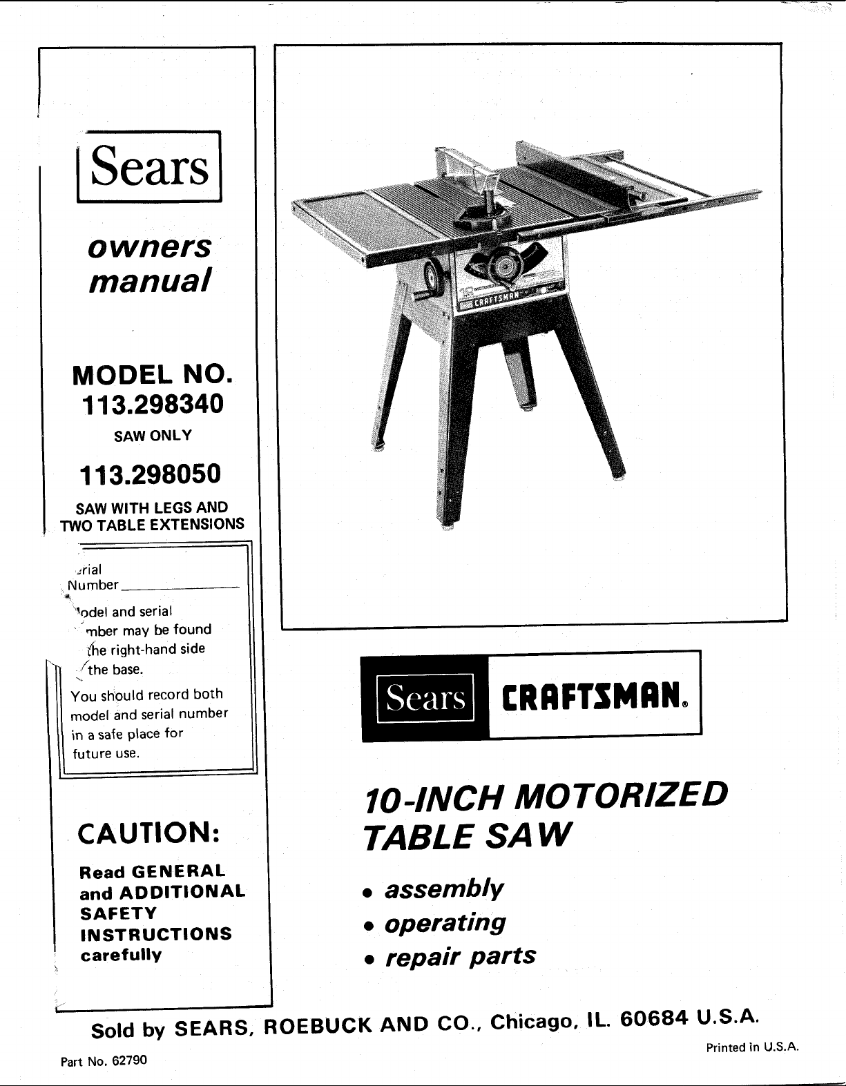
MODEL NO.
113.298340
SAW ONLY
113.298050
SAW WITH LEGS AND
TWO TABLE EXTENSIONS
:rial
Number
%del and serial
tuber may be found
_he right-hand side
" .ifthe base.
You should record both
model and serial number
in a safe place for
future use.
L
CAUTION:
Read GENERAL
and ADDITIONAL
SAFETY
INSTRUCTIONS
carefully
I
Sold by SEARS, ROEBUCK AND CO., Chicago, IL. 60684 U.S.A.
Part No, 62790
[RRFTSMRN°
IO-INC/MO_ED
TABLE SAW
• assembly
•operattng
•repatr parts
Printed in U.S.A.
FULL ONE YEAR WARRANTY ON CRAFTSMAN TABLE SAWS
If within one year from the date of purchase, this Craftsman Table Saw fails due to a defect in material or
workmanship, Sears will repair it, free of charge,
WARRANTY SERVICE IS AVAILABLE BY SIMPLY CONTACTING THE NEAREST SEARS STORE
OR SERVICE CENTER THROUGHOUT THE UNITED STATES.
This warranty gives you specific legal rights, and you may also have other rights which vary fr6m state to
state.
SEARS, ROEBUCK AND CO., Sears Tower, BSC 41-3, Chicago, IL 60684
general safety instructions for power tools
1. KNOW YOUR POWER TOOL
Read and understand the owner's manual and labels
affixed to the tool. Learn its application and
imitations as well as the specific potential hazards
peculiar to this tool.
2. GROUND ALL TOOLS
This tool is equipped with an approved 3-conductor
cord and a 3-prong grounding type _)lug to fit the
proper grounding type receptacle. The green conductor
in the cord is the grounding w=re. Never connect the
green w_re _o a live terminal.
3. KEEP GUARDS IN PLACE
_n working order, and in proper adjustment and
alignment.
4. REMOVE ADJUSTING KEYS
AND WRENCHES
Form habit of checking to see that keys and adjusting
wrenches are removed from tool before turning it on.
5. KEEP WORK AREA CLEAN
Cluttered areas and benches invite accidents. Floor
must not be slippery due to wax or sawdust.
6. AVOID DANGEROUS ENVIRONMENT
Don't use power tools in damp or wet locations or
expose them to rain. Keep work area well lighted.
Provide adequate surrounding work space.
7. KEEP CHILDREN AWAY
All visitors should be kept a safe distance from work
area.
8. MAKE WORKSHOP KID-PROOF
- with padlocks, master switches, or by removing
starter keys.
9. DON'T FORCE TOOL
It wi!l do the job better and'safer at the rate for which
it was designed.
10. USE RIGHT TOOL
Don't force tool or attachment to do a job it was not
designed for.
11. WEAR PROPER APPAREL
Do not wear loose clothing, gloves, neckties or jewelry
(rings, wrist watches) to get caught in moving parts,
Nonslip footwear is recommended. Wear protective
hair covering to contain long hair. Roll long sleeves
above the elbow.
12. USE SAFETY GOGGLES (Head Protection)
Wear Safety goggles (must comply with ANSI Z87.1)
at all times. Everyday eyeglasses only have impact
resistant lenses, they are NOT safety glasses. Also, use
face or dust mask if cutting operation is dusty, and ear
protectors (plugs or muffs) during extended periods of
operation.
13. SECURE WORK
Use clamps or a vise to hold work when practical. It's
safer than using your hand, frees both hands to operate
tool.
14. DON'T OVERREACH
Keep proper footing and balance at all times.
15.
MAINTAIN TOOLS WITH CARE
Keep tools sharp and clean for best and safest
performance. Follow' instructions for lubricating and
changing accessories.
16.
DISCONNECT TOOLS
before servicing; when changing accessories such as
blades, bits, cutters, etc.
17.
AVOID ACCIDENTAL STARTING
Make sure switch is in "OFF" position before plugging
in.
18. USE RECOMMENDED ACCESSORIES
Consult the owner's manual for recommended
accessories. Follow the instructions that accompany
the accessories. The use of improper accessories may
cause hazards,
19' NEVER STAND ON TOOL
Serious injury could occur if the too! is tipped or if the
cutting tool is accidentally contacted:
Do not store materials above or near the tool such that
it is necessary to stand on the tool to reach them,
20.
CHECK DAMAGED PARTS
Before further use of the tool, a guard or other part that
is damaged should be carefully checked to ensure that it
wilf operate properly and perform its intended function.
Check for alignment of moving parts, binding of moving
parts, breakage of parts, mounting, and any other
conditions that may .affect its operation, A guard or
other part that is damaged should be properly repaired
or replaced.
21. DIRECTION OF FEED
Feed work into a blade or cotter against the direction
of rotation of the blade or cutter only.
22. NEVER LEAVE TOOL RUNNING
UNATTENDED
Turn power off. Don't leave tool until it comes to a
complete stop.

ADDITIONAL SAFETY INSTRUCTIONS FOR TABLE SAWS
WARNING: FOR YOUR OWN SAFETY, DO NOT
OPERATE YOUR SAW UNTIL IT IS COMPLETELY
ASSEMBLED AND INSTALLED ACCORDING TO THE
INSTRUCTIONS... AND UNTIL YOU HAVE READ
AND UNDERSTAND THE FOLLOWING,
1. GENERAL SAFETY INSTRUCTIONS FOR POWER
TOOLS... SEE PAGE 2
2. GETTING TO KNOW YOUR SAW... SEE PAGE 15
3. BASIC SAW OPERATION... SEE PAGE 17
4. ADJUSTMENTS... SEE PAGE 24
5. MAINTENANCE,,, SEE PAGE 27
6. STABILITY OF SAW
If there =sany tendency for the saw to tip over or move
during certain cutting operations such as cutting
extremely large heavy panels or long heavy boards, the
saw should be bolted down.
If you attach any kind of table extensions over 24"
wide to either end of the saw, make sure you either
bolt the saw to the bench or floor as appropriate, or
support the outer end of the extension from the bench
or floor, asappropriate.
7. LOCATION
The saw should be positioned so neither the operator
nor a casual observer is forced to stand in line with the
saw blade.
8. KICKBACKS
A "KICKBACK" occurs during a rip:type operation
when a part or all of the workpiece is thrown back
violently toward the operator.
Keep your face and body to one side of the sawblade,
out of line with a possible "Kickback."
Kickbacks - and possible injury from them can
usually be avoided by:
A. Maintaining the rip fence parallel to the sawblade.
B. Keeping the sawblade sharp. Replacing antikickback
pawls when points become dull.
C. Keeping sawblade guard, spreader, and antikickback
pawls in place and operating properly. The spreader
must be in alignment with the sawblade and the
pawls must stop a kickback once it has started.
Check their action before ripping.
D. NOT ripping work that is twisted or warped or does
not have a straight edge to guide along the rip fence.
E. NOT releasing work until you have pushed it all the
way past the sawblade.
F. Using a "PUSH STICK" (See Page 18) for ripping
widths of 2 to 6 in,, and an auxiliary fence and push
block for ripping widths narrower than 2 in. (See
"Basic Saw Operation Using The Rip Fence" section.)
G. NOT confining the cut-off piece when ripping or
crosscutting.
H. When ripping apply the feed force to the section of
the workpiece between the saw blade and the rip
fence.
9. PROTECTION: EYES, HANDS, FACE, EARS, BODY
/_ If any part of your saw is malfunctioning, has been
damaged or broken. . such as the motor switch, or
other operating control, a safety device or the
power cord .. cease operating immediately until
the particular part is properly repaired or replaced.
B. Wear safety goggles that comply with ANSI Z87.1,
and a face shield if operation is dusty. Wear ear
plugs or muffs during extended periods of
operation.
C. Small loose ;)ieces of wood or other objects that
contact the rear of the revolving blade can be
thrown back at the operator at excessive speed. This
can usually be avoided by keeping the guard and
spreader in place for all "THRU-SAWING"
operations (sawing entirely thru the work) AND by
removing all loose pieces from the table with a long
stick of wood IMMEDIATELY after they are cut
off.
D. Use extra caution when the guard assembly is
removed for resawing, dadoing, rabbeting, or
molding - replace the guard as soon as that
operation is corn pleted.
E. NEVER turn the saw "ON" before clearing the
table of all tools, wood scraps, etc., except the
workpiece and related feed or support devices for
the operation planned.
F. NEVER place your face or body in line with the
cutting tool.
G. NEVER place your fingers or hands in the path of
the sawblade or other cutting tool.
H. NEVER reach in back of the cutting tool with
either hand to hold down or support the workpiece,
remove wood scraps, or for any other reason. Avoid
awkward operations and hand positions where a
sudden slip could cause fingers or hand to move
nto a sawblade or other cutting tool.
I DO NOT perform any operation "FREEHAND" -
always use either the rip fence or the miter gauge to
position and guide the work
J. NEVER use the rip fence when crosscutting or the
miter gauge when ripping. DO NOT use the rip
fence as a length stop.
Never hold onto or touch the "free end" of the
workpiece or a "free piece" that is cut off, while
power is "ON" and/or the sawblade is rotating.
K. Shut "OFF" the saw and disconnect the power cord
when removing the table insert, changing the
cutting tool, removing or replacing the blade guard,
or making adjustments.
L. Provide adeauate support to the rear and sides of
the saw table for wider'or long workpieces.
M. Plastic and composition (like hardboard) materials
may be cut on your saw. However, since these are
usually quite hard and slippery, the antikickback
pawls may not stop a kickback.
Therefore, be especially attentive to following
proper set-up and cutting procedures for ripping.
Do not stand, or perm=t anyone else to stand, in line
with a potential kickback.
N. DO NOT perform layout, assembly, or setup work
on the table while the cutting tool is rotating.
O. If you stall or jam the sawblade in the workpiece,
turn saw "OFF", remove the workpiece from the
sawblade, and check to see if the sawblade is
parallel to the miter gauge grooves and if the
spreader is in proper alignment with the sawblade.
If ripping at the time, check to see if the rip fence is
parallel with the sawblade. Readjust as indicated.
P. DO NOT remove small pieces of cut-off material
that may become trapped inside the blade guard
while the saw is running. This could endanger vour
hands or cause a kickback. Turn saw "OFF" and
wait until blade stops.
10. KNOW YOUR CUTTING TOOLS
A. Dull, gummy, or improperly sharpened or setcutting
tools can cause material to stick, jam, stall the saw,
or kickback at the opelator.
Minimize potential injury by proper cutting tool
and machine maintenance.
NEVER ATTEMPT TO FREE A STALLED
SAWBLADE WITHOUT FIRST TURNING THE
SAW OFF.
B. Neverusegrindingwheels,abrasivecut-offwheels.
frictionwheels(metalslittingblades)wirewheelsor
buffingwheels.
11.USE ONLY ACCESSORIES DESIGNED FOR THIS
SAW.
12_.Crosscutting operations are more conveniently worked
and with greater safety if an auxiliary wood facing is
attached to the miter gauge using the holes provided.
However, the facing must not interfere with the proper
functioning of the sawblade guard.
13. Make sure the top of the arbor or cutting tool rotates
toward you when standing in normal operating
position Also make sure the cutting tool, arbor collars
and arbor nut are installed properly. Keep the cutting
tool as low as possible for the operation being
performed. Keep all guards in place whenever possible.
14. Do not use any blade or other cutting tool marked for
an operating speed less than 3450 RPM. Never use a
cutting tool larger in diameter than the diameter for
which the saw was designed. For greatest safety and
efficiency when ripping, use the maximum diameter
blade for which the saw is designed, since under these
conditions the spreader is nearest the blade.
15. Adjust table inserts flush with the table top. NEVER
Operate the saw unless the proper insert is installed.
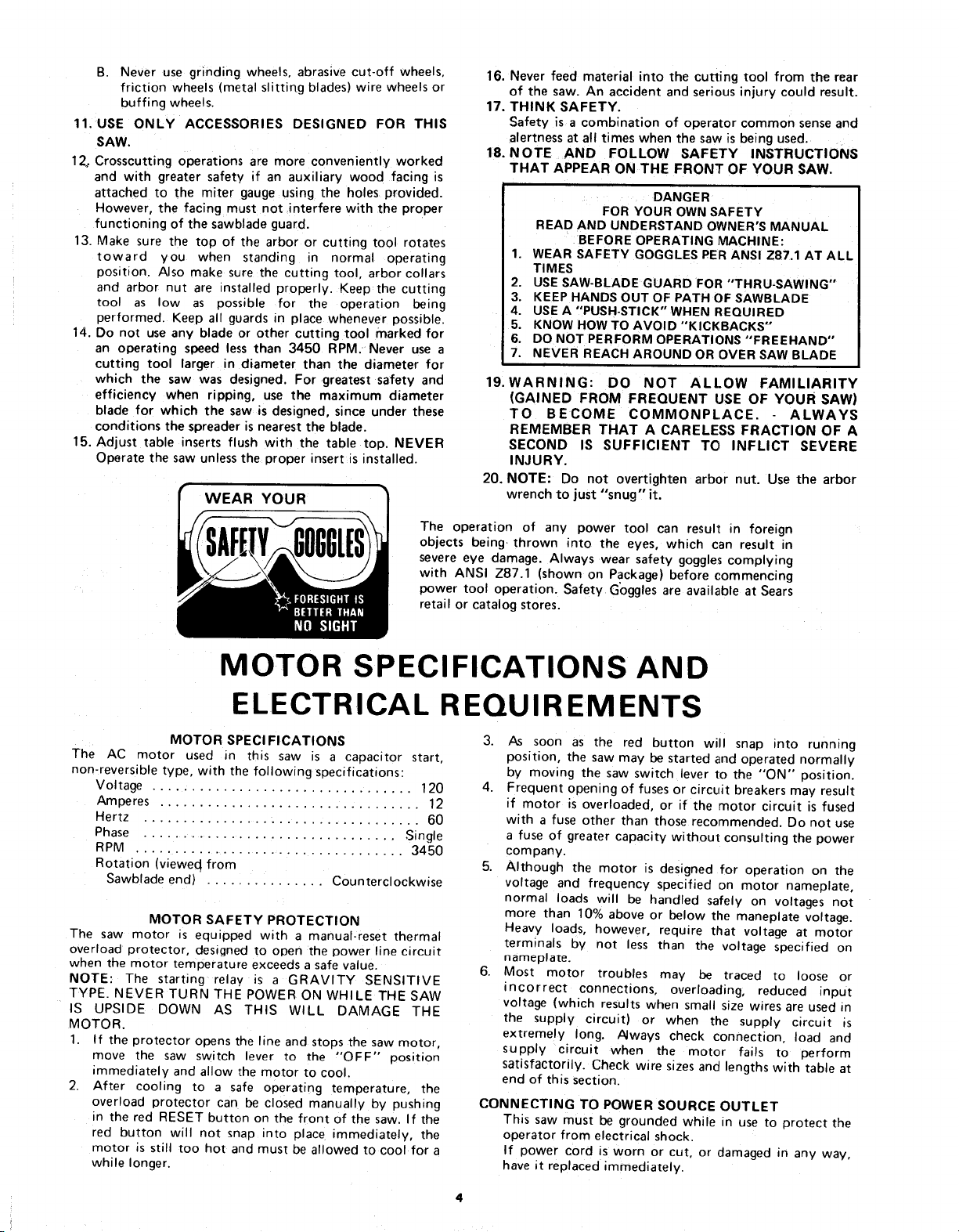
WEAR YOUR
The operation of any power tool can result in foreign
objects being, thrown into the eyes, which can result in
severe eye damage. Always wear safety goggles complying
with ANSI Z87.1 (shown on Package) before commencing
power tool operation. Safety Goggles are available at Sears
16. Never feed material into the cutting tool from the rear
of the saw. An accident and seriousinjury could result.
17. THINK SAFETY.
Safety is a combination of operator common senseand
alertness at all times when the saw is being used.
18. NOTE AND FOLLOW SAFETY INSTRUCTIONS
THAT APPEAR ON THE FRONT OF YOUR SAW,
DANGER
FOR YOUR OWN SAFETY
READ AND UNDERSTAND OWNER'S MANUAL
BEFORE OPERATING MACHINE:
1. WEAR SAFETY GOGGLES PER ANSI Z87.1 AT ALL
TIMES
2. USE SAW-BLADE GUARD FOR "THRU-SAWING"
3. KEEP HANDS OUT OF PATH OF SAWBLADE
4. USE A "PUSH-STICK"WHEN REQUIRED
5. KNOW HOW TO AVOID "KICKBACKS"
6. DO NOT PERFORM OPERATIONS "FREEHAND"
7. NEVER REACH AROUND OR OVER SAW BLADE
19. WARNING: DO NOT ALLOW FAMILIARITY
(GAINED FROM FREQUENT USE OF YOUR SAW)
TO BECOME COMMONPLACE. ALWAYS
REMEMBER THAT A CARELESS FRACTION OF A
SECOND IS SUFFICIENT TO INFLICT SEVERE
INJURY.
20. NOTE: Do not overtighten arbor nut. Use the arbor
wrench to just "snug" it.
retail or catalog stores.
MOTOR SPECIFICATIONS AND
ELECTRICAL REQUIREMENTS
MOTOR SPECI FICATIONS
The AC motor used in this saw is a capacitor start,
non-reversible type, with the following specifications:
Voltage ................................. 120
Amperes ................................. 12
Hertz ................ : .................. 60
Phase ................................ Single
RPM ................................... 3450
Rotation (vieweq from
Sawblade end) ............... Counterclockwise
MOTOR SAFETY PROTECTION
The saw motor is equipped with a manual-reset thermal
overload protector, designed to open the power line circuit
when the motor temperature exceeds a safe value.
NOTE: The starting relay is a GRAVITY SENSITIVE
TYPE. NEVER TURN THE POWER ON WHILE THE SAW
IS UPSIDE DOWN AS THIS WILL DAMAGE THE
MOTOR.
1. If the protector opens the line and stops the saw motor,
move the saw switch lever to the "OFF" position
immediately and allow the motor to cool.
2. After cooling to a safe operating temperature, the
overload protector can be closed manually by pushing
in the red RESET button on the front of the saw. If the
red button will not snap into place immediately, the
motor is still too hot and must be allowed to cool for a
while longer.
3. /ks soon as the red button will snap into running
position, the saw may be started and operated normally
by moving the saw switch lever to the "'ON" position.
4. Frequent opening of fuses or circuit breakers may result
if motor is overloaded, or if the motor circuit is fused
with a fuse other than those recommended. Do not use
a fuse of greater capacity without consulting the power
company.
5. Although the motor is designed for operation on the
voltage and frequency specified on motor nameplate,
normal loads will be handled safely on voltages not
more than 10% above or below the maneplate voltage.
Heavy loads, however, require that voltage at motor
terminals by not less than the voltage specified on
nameplate.
6. Most motor troubles may be traced to loose or
incorrect connections, overloading, reduced input
voltage (which results when small size wires are used in
the supply circuit) or when the supply circuit is
extremely long. Always check connection, load and
supply circuit when the motor fails to perform
satisfactorily. Check wire sizes and lengths with table at
end of this section.
CONNECTING TO POWER SOURCE OUTLET
This saw must be grounded while in use to protect the
operator from electrical shock.
If power cord is worn or cut, or damaged in any way,
have it replaced immediately.
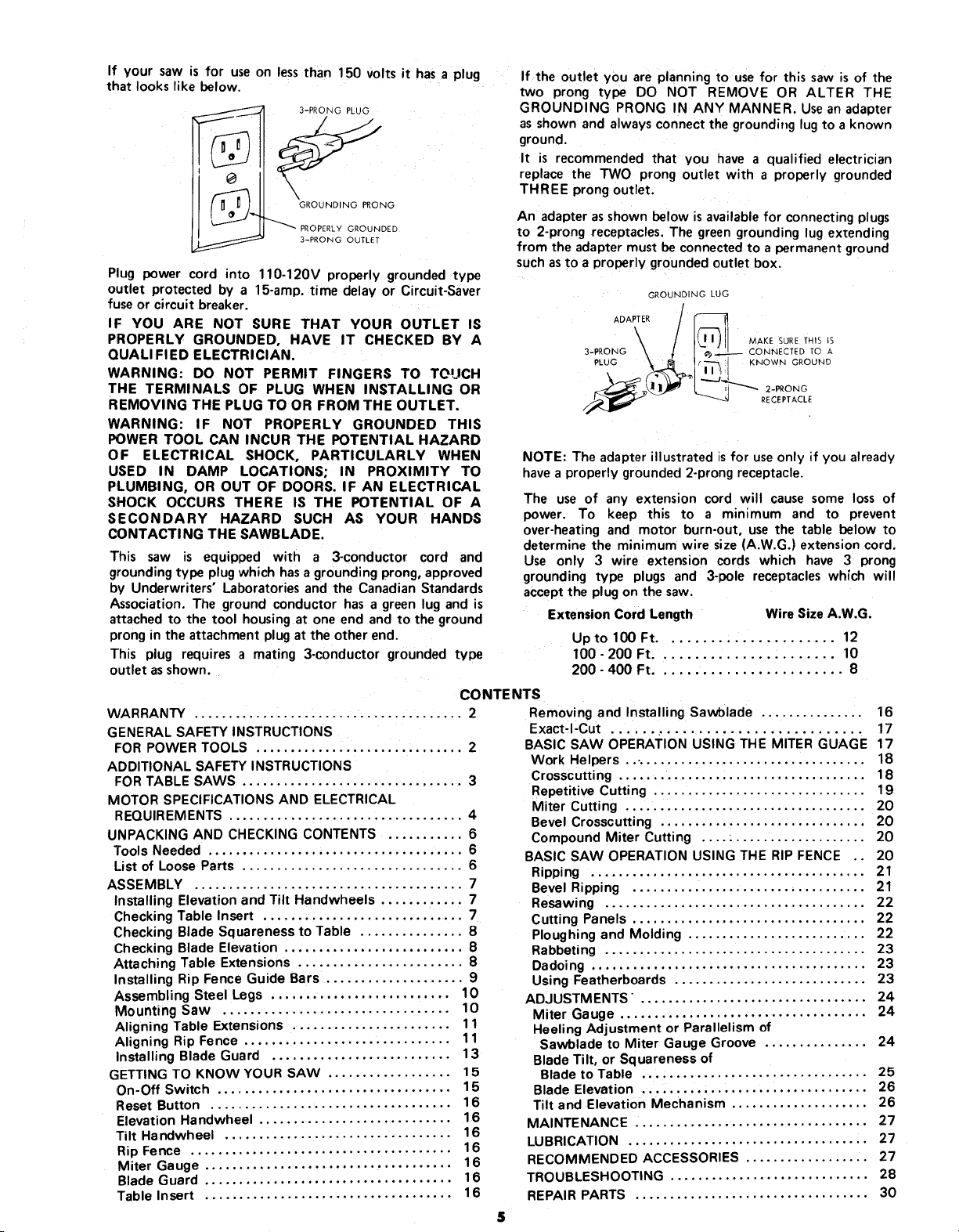
If your saw is for use on less than 150 volts it has a plug
that looks like below.
3-PRONG PLUG
(_ _GROUNDING PRONG
_ PROPERLY GROUNDED
3-PRONG OUTLET
Plug power cord into 110-120V properly grounded type
outlet protected by a 15-amp. time delay or Circuit-Saver
fuse or circuit breaker.
IF YOU ARE NOT SURE THAT YOUR OUTLET IS
PROPERLY GROUNDED, HAVE IT CHECKED BY A
QUALI FlED ELECTRICIAN.
WARNING: DO NOT PERMIT FINGERS TO TOUCH
THE TERMINALS OF PLUG WHEN INSTALLING OR
REMOVING THE PLUG TO OR FROM THE OUTLET.
WARNING: IF NOT PROPERLY GROUNDED THIS
POWER TOOL CAN INCUR THE POTENTIAL HAZARD
OF ELECTRICAL SHOCK, PARTICULARLY WHEN
USED IN DAMP LOCATIONS; IN PROXIMITY TO
PLUMBING, OR OUT OF DOORS. IF AN ELECTRICAL
SHOCK OCCURS THERE IS THE POTENTIAL OF A
SECONDARY HAZARD SUCH AS YOUR HANDS
CONTACTING THE SAWBLADE.
This saw is equipped with a 3-conductor cord and
grounding type plug which has agrounding prong, approved
by Underwriters' Laboratories and the Canadian Standards
Association. The ground conductor has a green lug and is
attached to the tool housing at one end and to the ground
prong in the attachment plug at the other end.
This plug requires a mating 3-conductor grounded type
outlet asshown.
CO NTE NTS
WARRANTY ....................................... 2
GENERAL SAFETY INSTRUCTIONS
FOR POWER TOOLS .............................. 2
ADDITIONAL SAFETY INSTRUCTIONS
FOR TABLE SAWS ................................ 3
MOTOR SPECIFICATIONS AND ELECTRICAL
REQUIREMENTS .................................. 4
UNPACKING AND CHECKING CONTENTS ........... 6
Tools Needed ..................................... 6
List of Loose Parts ................................ 6
ASSEMBLY ....................................... 7
Installing Elevation and Tilt Handwheels ............ 7
Checking Table Insert ............................. 7
Checking Blade Squareness to Table ............... 8
Checking Blade Elevation .......................... 8
Attaching Table Extensions ........................ 8
Installing Rip Fence Guide Bars .................... 9
Assembling Steel Legs .......................... 10
Mounting Saw ................................. 10
Aligning Table Extensions ....................... 11
Aligning Rip Fence .............................. 11
Installing Blade Guard .......................... 13
GETTING TO KNOW YOUR SAW .................. 15
On-Off Switch .................................. 15
Reset Button ................................... 16
Elevation Handwheel ............................ 16
Tilt Ha ndwheel ................................. 16
Rip Fence ...................................... 16
Miter Gauge ................................... 16
Blade Guard .................................... 16
Table Insert .................................... 16
If the outlet you are planning to use for this saw psof the
two prong type DO NOT REMOVE OR ALTER THE
GROUNDING PRONG IN ANY MANNER. Usean adapter
as shown and always connect the grounding lug to a known
ground.
It is recommended that you have a qualified electrician
replace the TWO prong outlet with a properly grounded
THREE prong outlet.
An adapter asshown below is available for connecting plugs
to 2-prong receptacles. The green grounding lug ex_ending
from the adapter must be connected to a permanent ground
suchas to a pro perly grounded outlet box.
GROUNDING LUG
ADAPTER
\
3-PRONG CONNECTED ro A
PLUG KNOWN GROUND
MAKE SURE THIS 15
2-PRONG
RECEPTACLE
NOTE: The adapter illustrated isfor useonly if you already
have a properly grounded 2-prong receptacle.
The use of any extension cord will cause some loss of
power. To keep this to a minimum and to prevent
over-heating and motor burn-out, use the table below to
determine the minimum wire size (A.W.G.) extension cord.
Use only 3 wire extension cords which have 3 prong
grounding type plugs and 3-pole receptacles which will
accept the plug on the saw.
Extension Cord Length Wire Size A.W.G.
Uptol00Ft ...................... 12
100-200 Ft ....................... 10
200-400 Ft........................ 8
Removing and Installing Sawblade ............... 16
Exact-I-Cut ................................ 17
BASIC SAW OPERATION USING THE MITER GUAGE 17
Work Helpers ... ................................. 18
Crosscutting .................................... 18
Repetitive Cutting ............................... 19
Miter Cutting ................................... 20
Bevel Crosscutting .............................. 20
Compound Miter Cutting ........................ 20
BASIC SAW OPERATION USING THE RIP FENCE .. 20
Ripping ........................................ 21
Bevel Ripping .................................. 21
Resawing ...................................... 22
Cutting Panels .................................. 22
Ploughing and Molding .......................... 22
Rabbeting ...................................... 23
Dadoing ........................................ 23
Using Featherboards ............................ 23
ADJUSTMENTS'. ................................ 24
Miter Gauge .................................... 24
Heeling Adjustment or Parallelism of
Sawblade to Miter Gauge Groove ............... 24
Blade Tilt, or Squareness of
Blade to Table ................................. 25
Blade Elevation ................................. 26
Tilt and Elevation Mechanism .................... 26
MAINTENANCE .................................. 27
LUBRICATION ................................... 27
RECOMMENDED ACCESSORIES .................. 27
TROUBLESHOOTING ............................. 28
REPAIR PARTS .................................. 30
UNPACKING AND CHECKING CONTENTS
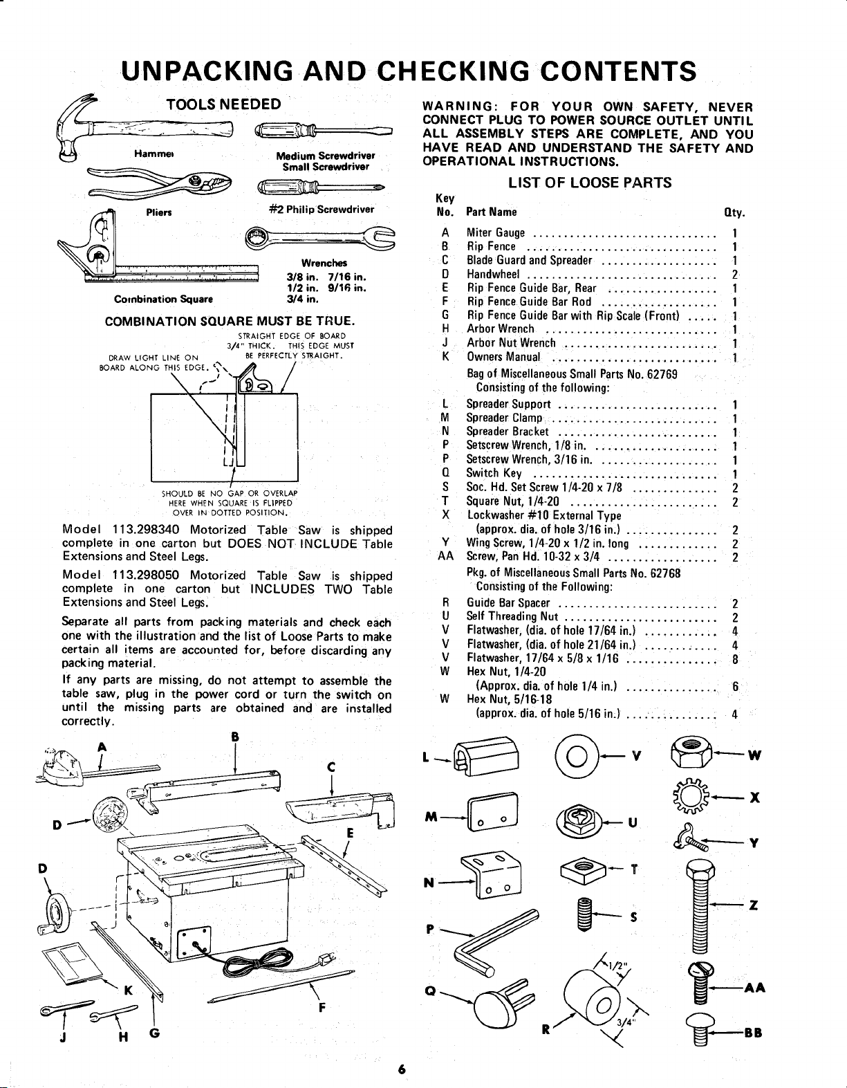
TOOLS NEEDED
Ha I1Rilllel
Pliers _ Philip Screwdriver
_, .:-'i_,.. :, _ ..,... :.._ 3/8 in. 7/16 in.
Combination Square 3/4 in.
, Wec
COMBINATION SQUARE MUST BE TRUE.
DRAW LIGHT LINE ON BE PERFECTLY STRAIGHT.
BOARD ALONG THIS EDGE. "?, ,_ /
3/4" THICK. [HIS EDGE MUST
Medium Screwdriver
Small Screwdriver
112in. 9/16 in.
STRAIGHT EDGE OF BOARD
\ ,--'i'fC_L /
LJII
SHOULD BE NO GAP OR OVERLAP
HERE WHEN SQUARE IS FLIPPED
OVER N DOTTED POSITION.
Model 113.298340 Motorized Table Saw is shipped
complete in one carton but DOES NOT INCLUDE Table
Extensions and Steel Legs.
Model 113.298050 Motorized Table Saw is shipped
complete in one carton but INCLUDES TWO Table
Extensions and Steel Legs.
Separate all parts from packing materials and check each
one with the illustration and the list of Loose Parts to make
certain all items are accounted for, before discarding any
packing material.
If any parts are missing, do not attempt to assemble the
table saw, plug in the power cord or turn the switch on
until the missing parts are obtained and are installed
correctly.
/
B
WARNING: FOR YOUR OWN SAFETY, NEVER
CONNECT PLUG TO POWER SOURCE OUTLET UNTIL
ALL ASSEMBLY STEPS ARE COMPLETE, AND YOU
HAVE READ AND UNDERSTAND THE SAFETY AND
OPERATIONAL INSTRUCTIONS.
LIST OF LOOSE PARTS
Key
No.
Part Name Qty.
A Miter Gauge ............................... 1
B Rip Fence ............................... 1
C Blade Guard and Spreader ................... 1
D Handwheel ............................... 2
E Rip Fence Guide Bar, Rear .................. 1
F Rip Fence Guide Bar Rod ................... 1
G Rip Fence Guide Bar with Rip Scale (Front) ..... 1
H Arbor Wrench ............................ 1
J Arbor Nut Wrench ......................... 1
K Owners Manual ........................... 1
Bagof Miscellaneous Small Parts No. 62769
Consisting of the following:
L Spreader Support .......................... 1
M Spreader Clamp ........................... 1
N Spreader Bracket .......................... 1
P Setscrew Wrench, 1/8 in..................... 1
P Setscrew Wrench, 3/16 in.................... 1
Q Switch Key .............................. 1
S Soc. Hd. Set Screw 1/4-20 x 7/8 .............. 2
T Square Nut, 1/4-20 ........................ 2
X Lockwasher #10 External Type
(approx. dia. of hole 3/16 in.) ............... 2
Y Wing Screw, 1/4-20 x 1/2 in. lung ............. 2
AA Screw, Pan Hd. 10-32 x 3/4 .................. 2
Pkg. of Miscellaneous Small Parts No. 62768
Consisting of the Following:
R Guide Bar Spacer .......................... 2
U Self Threading Nut ......................... 2
V Flatwasher, (dia. of hole 17/64 in.) ............ 4
V Flatwasber, (dia. of hole 21/64 in.) ............ 4
V Flatwasher, 17/64 x 5/8 x 1/16 ............... 8
W Hex Nut, 1/4-20
(Approx. dia. of hole 1/4 in.) ............... 6
W Hex Nut, 5/16-18
(approx. dia. of hole 5/16 in.) ............... 4
D
J H
C
E
Z
F
G
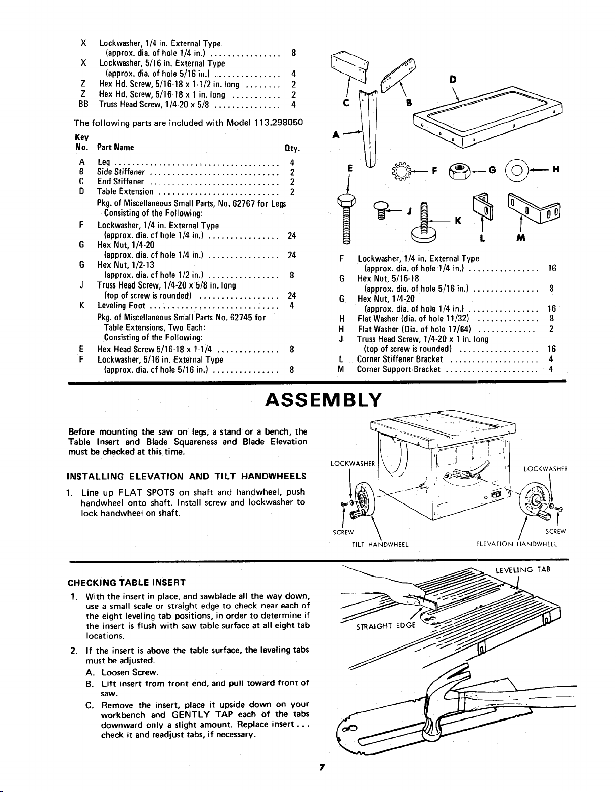
X Lockwasher,1/4 in. ExternalType
(approx.dia. ofhole 1/4in.) ................ 8
X L0ckwasher,5/16 in. ExternalType
(approx.dia.of hole5/16 in.) ............... 4
Z Hex Hd.Screw, 5/16-18 x 1-1/2 in. long ........ 2
Z Hex Hd.Screw, 5/16-18 x 1 in. long ........... 2
BB TrussHeadScrew,1/4-20 x 5/8 ............... 4
"]'hefollowing parts are included with Model 113.298050
Key
No.
Part Name Qty.
A Leg ..................................... 4
B Side Stiffener ............................. 2
C End Stiffener ............................. 2
D Table Extension ........................... 2
Pkg. of Miscellaneous Small Parts, No. 62767 for Legs
Consisting of the Following:
F Lockwasher, 1/4 in. External Type
(approx. dia. of hole 1/4 in.) ................ 24
G Hex Nut, 1/4-20
(approx. dia. of hole 1/4 in.) ................ 24
G Hex Nut, 1/2-13
(approx. dia. of hole 1/2 in.) ................ 8
J Truss Head Screw, 1/4-20 x 5/8 in. long
(top of screwis rounded) .................. 24
K Leveling Foot ............................. 4
Pkg. of Miscellaneous Small Parts No. 62745 for
Table Extensions, Two Each:
Consisting of the Following:
E Hex Head Screw 5/16-18 x 1-1/4 .............. 8
F Lockwasher, 5/16 in. External Type
(approx. dia. of hole 5/16 in.) ............... 8
D
s
!
E
l
L M
F Lockwasher,1/4 in. ExternalType
(approx.dia. of hole1/4 in.) ................ 16
G Hex Nut, 5/16-18
(approx.dia. of hole5/16 in.) ............... 8
G HexNut, 1/4-20
(approx.dia. of hole1/4 in.) ................ 16
H FlatWasher(dia.ofhole 11/32) .............. 8
H Flat Washer(Dia. of hole 17/64) ............. 2
J TrussHeadScrew, 1/4-20x 1in. long
(topof screwisrounded) .................. 16
L CornerStiffener Bracket .................... 4
M CornerSupport Bracket ..................... 4
ASSEMBLY
Before mounting the saw on legs, a stand or a bench, the
Table Insert and Blade Squareness and Blade Elevation
must be checked at this time.
INSTALLING ELEVATION AND TILT HANDWHEELS
1. Line up FLAT SPOTS on shaft and handwheel, push
handwheel onto shaft. Install screw and Iockwasher to
lock handwheel on shaft.
CHECKING TABLE INSERT
1. With the insert in place, and sawblade all the way down,
use a small scale or straight edge to check near each of
the eight leveling tab positions, in order to determine if
the insert is flush with saw table surface at all eight tab
locations,
2. If the insert is above the table surface, the leveling tabs
must be adjusted.
A. LoosenScrew.
B. Lift insert from front end, and pull toward front of
saw.
C. Remove the insert, place it upside down on your
workbench and GENTLY TAP each of the tabs
downward only a slight amount. Replace insert ...
check it and readjust tabs, if necessary.
LOCKWASHER
SCREW
TILT HANDWHEEL
LOCKWASHER
rLEVATION HANDWHEEL
7
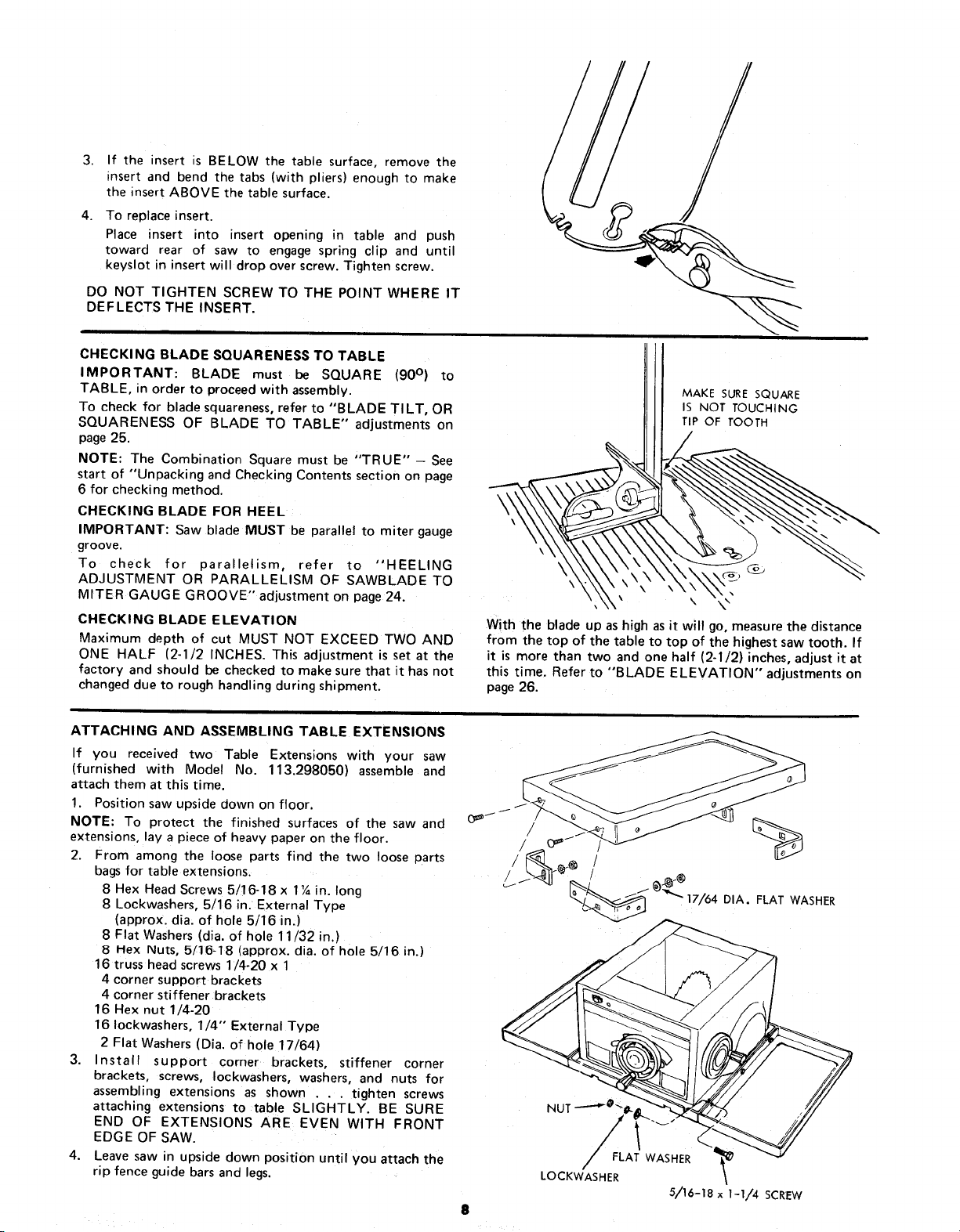
3. If the insert is BELOW the table surface, remove the
insert and bend the tabs (with pliers) enough to make
the insert ABOVE the table surface.
4. To replace insert.
Place insert into insert opening in table and push
toward rear of saw to engage spring clip and until
keyslot in insert will drop over screw. Tighten screw.
DO NOT TIGHTEN SCREW TO THE POINT WHERE IT
DEFLECTS THE INSERT.
CHECKING BLADE SQUARENESS TO TABLE
IMPORTANT: BLADE must be SQUARE (90 ° ) to
TABLE, in order to proceed with assembly.
To check for blade squareness,refer to "BLADE TI LT, OR
SQUARENESS OF BLADE TO TABLE" adjustments on
page 25.
NOTE: The Combination Square must be "TRUE" - See
start of "Unpacking and Checking Contents section on page
6 for checking method.
CHECKING BLADE FOR HEEL
IMPORTANT: Saw blade MUST be parallel to miter gauge
groove.
To check for parallelism, refer to "HEELING
ADJUSTMENT OR PARALLELISM OF SAWBLADE TO
MITER GAUGE GROOVE" adjustment on page 24.
CHECKING BLADE ELEVATION
Maximum depth of cut MUST NOT EXCEED TWO AND
ONE HALF (2-1/2 INCHES. This adjustment is set at the
factory and should be checked to make sure that it has not
changed due to rough handling during shipment.
MAKE SURE SQUARE
IS NOT TOUCHING
TIP OF TOOTH
\
\
\
\
With the blade up as high as it will go, measure the distance
from the top of the table to top of the highest saw tooth. If
it is more than two and one half (2-1/2) inches, adjust it at
this time. Refer to "BLADE ELEVATION" adjustments on
page 26.
ATTACHING AND ASSEMBLING TABLE EXTENSIONS
If you received two Table Extensions with your saw
(furnished with Model No. 113.298050) assemble and
attach them at this time.
1. Position saw upside down on floor.
NOTE: To protect the finished surfaces of the saw and
extensions, lay a piece of heavy paper on the floor.
2. From among the loose parts find the two loose parts
bags for table extensions.
8 Hex Head Screws 5/16-18 x 1_ in. long
8 Lockwashers, 5/16 in. External Type
(approx. dia. of hole 5/16 in.)
8 Flat Washers (dia. of hole 11/32 in.)
8 Hex Nuts, 5/15-18 (approx. dia. of hole 5/16 in.)
16 truss head screws 1/4-20 x 1
4 corner support brackets
4 corner stiffener brackets
16 Hex nut 1/4-20
16 Iockwashers, 1/4" External Type
2 Flat Washers (Dia. of hole 17/64)
3. Install support corner brackets, stiffener corner
brackets, screws, Iockwashers, washers, and nuts for
assembling extensions as shown . . . tighten screws
attaching extensions to table SLIGHTLY. BE SURE
END OF EXTENSIONS ARE EVEN WITH FRONT
EDGE OF SAW.
4. Leave saw in upside down position until you attach the
rip fence guide bars and legs.
NUT ---_
_FLFLAT WASHER
LOCKWASHER
5/16-18 x I-I/4 SCREW

INSTALLING RIP FENCE GUIDE BARS
1. From among the loose parts find the following
hardware:
2 Hex. Head Screws, 5/16 - 18 x 1-1/2 in. long
2 Hex. Head Screws, 5/16- 18 x 1 in. long
4 Hex. Nuts, 5/16 - 18 (approx. dia. of hole 5/16 in.)
4 External Lockwashers, 5/16 in. (approx. dia. of hole
5/16 in.)
4 Flat Washers(Dia. of hole 21/64 in.)
2 Spacers, 3/4 in. dia. x 1/2 in. long
2 Self-threading nuts
2. Position guide bars on floor and install hardware as
shown.., do not screw nuts on all the way.
EXT. LOCKWASHER HEX. HEAD SCREW
5/16 IN. 1 IN. LONG
FLAT WASHER /
HEX NUT
5/16 IN.
/
REAR GUIDE BAR
3. Place front guide bar against saw table and drop it in
place ... engagingthe screwsin the slots. Make sure the
spacersare between the rail and the table.
4. End of front guide bar must be 7-5/16 in. from side of
saw table. This is important so that rip fence Indicator
can be aligned.
5. With the blade of your combination square set to 1/4
in., use it as a gauge and attach the rail so that the edge
of the rail is 1/4 in. ABOVE the edgeof the table.
,
Remove the three screws from rear of table extension.
7.
Insert ends of FENCE GUIDE BAR ROD through
round holesat outer end of bars.
NOTE: The ends of the ROD are not threaded ... the
SELF THREADING NUTS will cut threads on the rod
as they are'screwed on.
o
Attach the rear bar in a similar manner, but make sure
that the end of the bar is 12-3/16 in. from the side of
the saw table.
SAW TABLE
//_// 7-5/16 IN.
FENCE GUIDE BAR ROD
9
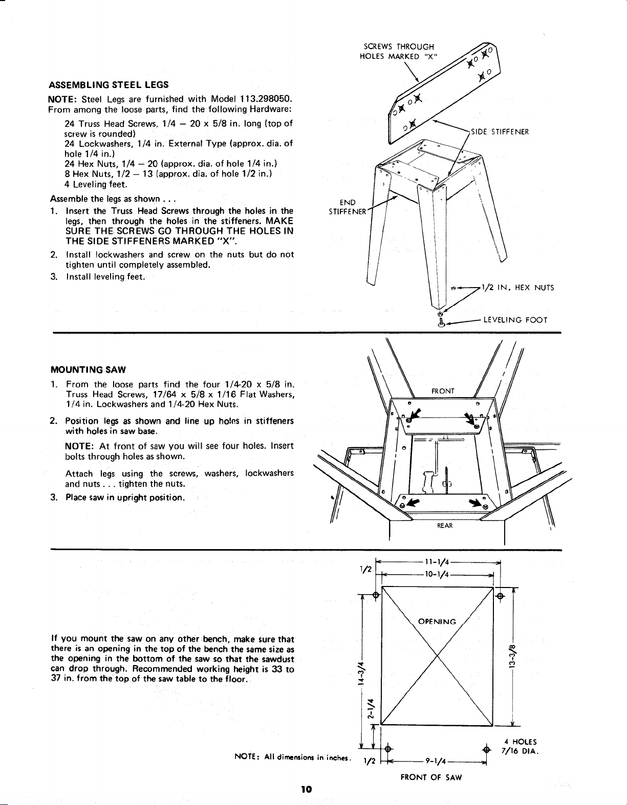
ASSEMBLING STEEL LEGS
NOTE: Steel Legs are furnished with Model 113.298050.
From among the loose parts, find the following Hardware:
24 Truss Head Screws, 1/4 - 20 x 5/8 in. long (top of
screw is rounded)
24 Lockwashers, 1/4 in. External Type (approx. dia. of
hole 1/4 in.)
24 Hex Nuts, 1/4 -- 20 (approx. dia. of hole 1/4 in.)
8 Hex Nuts, 1/2 - 13 (approx. dia. of hole 1/2 in.)
4 Leveling feet.
Assemble the legs as shown...
1. Insert the Truss Head Screws through the holes in the
legs, then through the holes in the stiffeners. MAKE
SURE THE SCREWS GO THROUGH THE HOLES IN
THE SIDE STIFFENERS MARKED "X".
2. Install Iockwashers and screw on the nuts but do not
tighten until completely assembled.
3. Install leveling feet.
SCREWS THROUGH
HOLES MARKED "X"
STIFFENER
END
IN. HEX NUTS
_._.__.------- LEVELING FOOT
MOUNTING SAW
1. From the loose parts find the four 1/4:20 x 5/8 in.
Truss Head Screws, 17/64 x 5/8 x 1/16 Flat Washers,
1/4 in. Lockwashers and 1/4:20 Hex Nuts.
2. Position legs as shown and line up holes in stiffeners
with holes in saw base,
NOTE: At front of saw you will see four holes. Insert
bolts through holes as shown.
Attach legs using the screws, washers, Iockwashers
and nuts.., tighten the nuts.
3.
Place saw in upright position.
If you mount the saw on any other bench, make sure that
there is an opening in the top of the bench the same size as
the opening in the bottom of the saw so that the sawdust
can drop through. Recommended working height is 33 to
37 in. from the:top of the saw table to the floor.
FRONT
REAR
11-I/4
Io-v4
NOTE: All dimensions in inches.
10
4 HOLES
7/16 DIA.
i/4
FRONT OF SAW
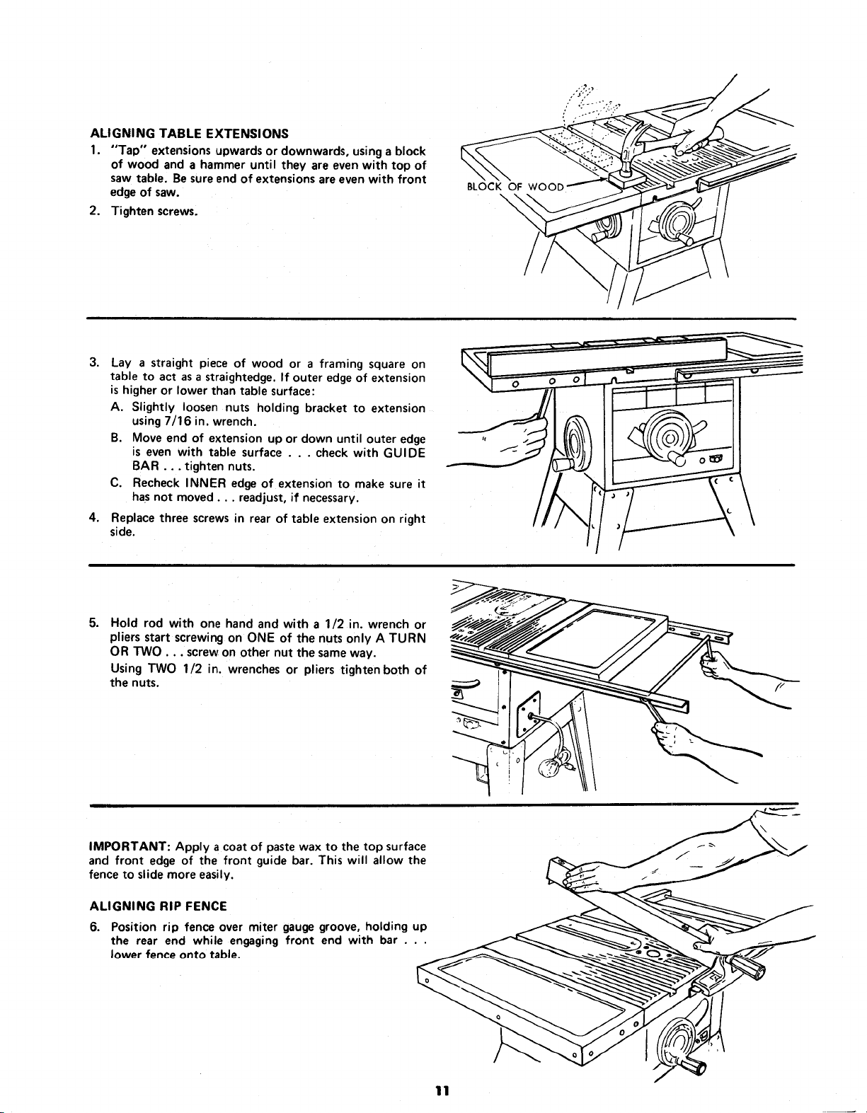
ALIGNING TABLE EXTENSIONS
1. "Tap" extensions upwards or downwards, using a block
of wood and a hammer until they are even with top of
saw table. Be sure end of extensions are even with front
edgeof saw.
2. Tighten screws.
3.
Lay a straight piece of wood or a framing square on
table to act asa straightedge. If outer edgeof extension
ishigher or lower than table surface:
A. Slightly loosen nuts holding bracket to extension
using 7/16 in. wrench.
B. Move end of extension up or down until outer edge
is even with table surface . . . check with GUIDE
BAR... tighten nuts.
C. Recheck INNER edge of extension to make sure it
hasnot moved.., readjust, if necessary.
4. Replace three screws in rear of table extension on right
side.
BLOCK OF WOOE;
\
5. Hold rod with one hand and with a 1/2 in. wrench or
pliers start screwing on ONE of the nuts only A TURN
OR TWO... screwon other nut the sameway.
Using TWO 1/2 in. wrenches or pliers tighten both of
the nuts.
IMPORTANT: Apply a coat of paste wax to the top surface
and front edge of the front guide bar. This will allow the
fence to slide more easily.
ALIGNING RIP FENCE
6. Position rip fence over miter gauge groove, holding up
the rear end while engaging front end with bar . . .
lower fence onto table.
11
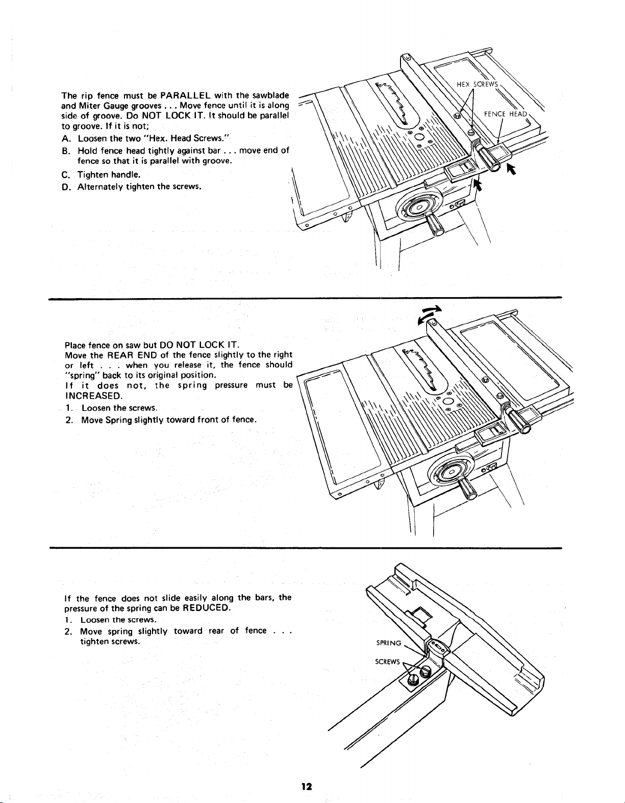
The rip fence must be PARALLEL with the sawblade
and Miter Gauge grooves... Move fence until it isalong
side of groove. Do NOT LOCK IT. It should be parallel
to groove. If it is not,
A. Loosen the two "Hex. Head Screws."
B. Hold fence head tightly against bar.., move end of
fence so that it is parallel with groove.
C. Tighten handle.
D. Alternately tighten the screws.
Place fence on saw but DO NOT LOCK IT.
Move the REAR END of the fence slightly to the right
or left . . . when you release it, the fence should
"spring" back to its original position.
If it does not, the spring pressure must be
INCREASED.
1. Loosen the screws.
2. Move Spring slightly toward front of fence.
\
If the fence does not slide easily along the bars, the
pressure of the spring can be REDUCED.
1. Loosen the screws.
2. Move spring slightly toward rear of fence . . .
tighten screws. SPRING
12
 Loading...