


|
TABLE OF CONTENTS |
Warranty.......................................................................................................................................................................................... |
2 |
Safety Instructions..................................................................................................................................................................................... |
2-3 |
Specifications...................................................................................................................................................... |
3 |
Glossary of Terms............................................................................................................................................ |
4 |
Safety........................................................................................................................................................................... |
5 |
Accessories and Attachments..................................................................................................................................... |
6 |
Carton Contents........................................................................................................................................ |
7 |
Assembly........................................................................................................................................... |
8-9 |
Adjustments...................................................................................................................................... |
10-12 |
Operation........................................................................................................................................ |
13-14 |
Maintenance & Troubleshooting.................................................................................................................................. |
15 |
Parts Diagram................................................................................................................................................................................. |
16 |
Parts Lists............................................................................................................................................ |
17-18 |
Repair Protection Agreement...................................................................................................................................... |
19 |
Español.......................................................................................................................................................................................... |
20 |
CRAFTSMAN ONE YEAR FULL WARRANTY
FOR ONE YEAR from the date of purchase, this product is warranted against any defects in material or workmanship. A defective product will receive free repair or replacement if repair is unavailable.
For warranty coverage details to obtain free repair or replacement, visit the web site: www.craftsman.com
This warranty is void if this product is ever used while providing commercial services or if rented to another person.
This warranty gives you specific legal rights, and you may also have other rights which vary from state to state.
Sears Brands Management Corporation, Hoffman Estates, IL 60179
Proposition 65 Warning:
WARNING: Some dust created by power sanding, sawing, grinding, drilling, and other construction activities contains chemicals known to the State of California to cause cancer and birth defects or other reproductive harm.
SAFETY INSTRUCTIONS
GENERAL SAFETY INSTRUCTIONS
BEFORE USING THE DRILL PRESS
Safety is a combination of common sense, staying alert and knowing how to use this Drill Press.
WARNING: To avoid mistakes that could cause serious injury, do not plug the Drill Press in until you have read and understood the following:
1.READ and become familiar with the entire Operator’s Manual. LEARN the tool’s application, limitations and possible hazards.
2.KEEP GUARDS IN PLACE and in working order.
3.REMOVE ADJUSTING KEYS AND WRENCHES. Form a habit of checking to see that keys and adjusting wrenches are removed from the tool before turning ON.
4.KEEP WORK AREA CLEAN. Cluttered areas and benches invite accidents.
5.DON’T USE IN DANGEROUS ENVIRONMENT. Don’t use power tools in damp or wet locations, or expose them to rain. Keep work area well lighted.
6.KEEP CHILDREN AWAY. All visitors should be kept at a safe distance from work area.
7.MAKE WORKSHOP CHILDPROOF with padlocks.
8.DON’T FORCE THE TOOL. It will do the job better and safer at the rate for which it was designed.
9.USE THE RIGHT TOOL. Do not force tool or attachment to do a job for which it was not designed.
10.USE PROPER EXTENSION CORD. Make sure your extension cord is in good condition. When using an extension cord, be sure to use one heavy enough to carry the current your product will draw. An undersized cord will result in a drop in line voltage and in loss of power that will cause the tool to overheat.
11.WEAR PROPER APPAREL. Do not wear loose clothing, gloves, neckties, rings, bracelets, or other jewelry that may get caught in moving parts. Nonslip footwear is recommended. Wear protective hair covering to contain long hair.
12.ALWAYS WEAR EYE PROTECTION. Any Drill Press can throw foreign objects into the eyes that could cause permanent eye damage. ALWAYS wear Safety Goggles (not glasses). Everyday eyeglasses have only impactresistance lenses. They ARE NOT safety glasses.
13.SECURE WORK. Use clamps or a vise to hold work when practical. It’s safer than using your hand and it frees both hands to operate tool.
14.DISCONNECT TOOLS before servicing; when changing accessories such as blades, bits, cutters, and the like.
15.REDUCE THE RISK OF UNINTENTIONAL STARTING.
Make sure switch is in OFF position before plugging in.
16.USE RECOMMENDED ACCESSORIES. Consult the Operator’s Manual for recommended accessories. The use of improper accessories may cause serious injury.
2

17.NEVER STAND ON TOOL. Serious injury could occur if the tool is tipped or if the cutting tool is unintentionally contacted.
18.CHECK FOR DAMAGED PARTS. Before further use of the tool, a guard or other part that is damaged should be carefully checked to determine that it will operate properly and perform its intended function – check for alignment of moving parts, binding of moving parts, breakage of parts, mounting, and any other conditions that may affect its operation. A guard or other part that is damaged should be properly repaired or replaced.
19.NEVER LEAVE TOOL RUNNING UNATTENDED. TURN POWER “OFF”. Don’t leave tool until it comes to a complete stop.
20.DON’T OVERREACH. Keep proper footing and balance at all times.
21.MAINTAIN TOOLS WITH CARE. Keep tools sharp and clean for best and safest performance. Follow instructions for lubricating and changing accessories.
22.DO NOT use power tools in the presence of flammable liquids or gases.
23.DO NOT OPERATE the tool if you are under the influence of any drugs, alcohol or medication that could affect your ability to use the tool properly.
24.ALWAYS operate the Drill Press in a well-ventilated area and provide for proper dust removal. Use dust collection systems whenever possible. Dust generated from certain materials can be hazardous to your health.
SPECIFIC SAFETY INSTRUCTIONS FOR DRILL PRESS
WARNING: For your own safety, do not try to use your drill press or plug it in until it is completely assembled and installed according to the instructions, and until you have read and understood this instruction manual.
1.THIS DRILL PRESS is intended for use in dry conditions, indoor use only.
2.WEAR EYE PROTECTION. USE a face or dust mask along with safety goggles if drilling operation is dusty. USE ear protectors, especially during extended periods of operation.
3.DO NOT wear gloves, neckties, or loose clothing.
4.DO NOT try to drill material too small to be securely held.
5.ALWAYS keep hands out of the path of a drill bit. Avoid awkward hand positions where a sudden slip could cause your hand to move into the drill bit.
6.DO NOT install or use any drill bit that exceeds 175mm
in length or extends 150mm below the chuck jaws. They can suddenly bend outward or break.
7.DO NOT USE wire wheels, router bits, shaper cutters, circle (fly) cutters, or rotary planers on this drill press.
8.WHEN cutting a large piece of material, make sure it is fully supported at the table height.
9.DO NOT perform any operation freehand. ALWAYS hold the workpiece firmly against the table so it will not rock or twist. Use clamps or a vise for unstable workpieces.
10.MAKE SURE there are no nails or foreign objects in the part of the workpiece to be drilled.
11.CLAMP THE WORKPIECE OR BRACE IT against the left side of the column to prevent rotation. If it is too short or the table is tilted, clamp it solidly to the table.
12.IF THE WORKPIECE overhangs the table such that it will fall or tip if not held, clamp it to the table or provide auxiliary support.
13.SECURE THE WORK. Use clamps or a vise to hold the work when practical. It’s safer than using your hand and it frees both hands to operate tool.
14.MAKE SURE all clamps and locks are firmly tightened before drilling.
15.SECURELY LOCK THE HEAD and table support to the column, and the table to the table support before operating the drill press.
16.NEVER turn your drill press ON before clearing the table of all objects (tools, scraps of wood, etc.).
17.BEFORE STARTING the operation, jog the motor switch to make sure the frill bit does not wobble or vibrate.
18.LET THE SPINDLE REACH FULL SPEED before starting to drill. If your drill press makes an unfamiliar noise or if it vibrates excessively, stop immediately, turn the drill press OFF and unplug. Do not restart the unit until the problem is corrected.
19.DO NOT perform layout assembly or set up work on the table while the drill press is in operation.
20.USE THE RECOMMENDED SPEED for any drill press accessory and for different workpiece material.
21.WHEN DRILLING large diameter holes, clamp the workpiece firmly to the table. Otherwise, the bit may grab and spin the workpiece at high speeds. DO NOT USE fly cutters or multiple part hold cutters, as they can come apart or become unbalanced in use.
22.MAKE SURE the spindle has come to a complete stop before touching the workpiece.
23.TO AVOID INJURY from accidental starting, always turn the switch OFF and unplug the drill press before installing or removing any accessory or attachment or making any adjustment.
SPECIFICATIONS
Motor............................................................. |
3/4 HP |
Base Size............... |
18.11" x 11.02" / 460 X 280mm |
Chuck................................................. |
0.63" / 16mm |
Column............................................... |
2.83" / 72mm |
Spindle Travel..................................... |
3.23" / 82mm |
Swing............................................. |
14.17" / 360mm |
Spindle Taper.................................................... |
MT2 |
Total Height.................................. |
61.61" / 1565mm |
Speed Change................................................... |
16 |
Weight...................................... |
137.79LBS / 62.5kg |
Speeds............................................ |
240 / 3470 rpm |
Box Dimensions.................... |
45.28X19.69"X11.81" |
SAVE THESE INSTRUCTIONS.
Refer to them often.
3

GLOSSARY OF TERMS
BASE – Supports drill press. For additional stability, holes are provided in base to bolt drill press to bench. BACKUP MATERIAL – A piece of scrap wood placed between the workpiece and table. The backup board prevents wood in the workpiece from splintering when the drill passes through the backside of the workpiece. It also prevents drilling into the table top.
HEAD ASSEMBLY – Covers the pulleys and belt during operation of the drill press.
BELT TENSION – Refer to the Assembly Section, “Installing and Tensioning Belt”.
BELT TENSION LOCK KNOBS – Tightening the knobs locks the motor bracket support and the belt tension handle, maintaining correct belt distance and tension. BEVEL SCALE – Shows degree of table tilt for bevel operations. The scale is mounted on the side of the table bracket.
CHUCK – Holds a drill bit or other recommended accessory to perform desired operations.
CHUCK KEY – A self-ejecting chuck key which will pop out of the chuck when you let go of it. This action is designed to help prevent throwing of the chuck key from the chuck when the power is turned ON. Do not use any other key as a substitute; order a new one if Damaged or Lost. COLUMN – Connects the head, table, and base on a one piece tube for easy alignment and movement. COLUMN COLLAR – Holds the rack to the column. The rack remains movable in the collar to permit table support movements.
COLUMN SUPPORT – Supports the column, guides the rack and provides mounting holes for the column to the base.
DEPTH SCALE STOP NUTS – Lock the spindle to a selected depth.
DEPTH SCALE – Indicates depth of hole being drilled. DRILL BIT – The cutting tool used in the drill press to make holes in a workpiece.
DRILL ON/OFF SWITCH – Has a locking feature. This feature is intended to help prevent unauthorized and possible hazardous use by children and others. Insert the key into the switch to turn the drill press on.
DRILLING SPEED – Changed by placing the belt in any of the steps (grooves) in the pulleys. See the Spindle Speed Chart inside belt guard or in the manual.
FEED HANDLE – Moves the chuck up or down. If necessary, one or two of the handles may be removed whenever the workpiece is of such unusual shape that it interferes with the handles.
RACK – Combines with gear mechanism to provide easy elevation of the table by the hand operated table crank.
RPM – Revolutions per minute. The number of turns completed by a spinning object in one minute.
SPINDLE SPEED – The RPM of the spindle.
SPRING CAP – Adjusts the spindle return spring tension.
TABLE BRACKET LOCKING HANDLE – Tightening locks the table support tot he column. Always have it locked in place while operating the drill press.
TABLE – Provides a working surface to support the workpiece.
TABLE ARM – Extends beyond the table support for mounting and aligning the table.
TABLE TILT LOCK BOLT – Locks the table in any position from 0° to 45°.
TABLE CRANK – Elevates and lowers the table. Turn clockwise to elevate the table. Support lock must be released before operating the crank.
TABLE LOCK – Locks the table after it is rotated to various positions.
TABLE BRACKET – Rides on the column to support the table arm and table.
WORKPIECE – Material being drilled.
4

SAFETY
ELECTRICAL REQUIREMENTS
POWER SUPPLY AND MOTOR SPECIFICATIONS
WARNING: To avoid electrical hazards, fire hazards, or damage to the tool, use proper circuit protection. Use a separate electrical circuit for your tools. To avoid shock or fire, if power cord is worn or cut, or damaged in any way, have it replaced immediately.
GROUNDING INSTRUCTIONS
WARNING: This tool must be grounded while in use to protect the operator from electrical shock.
IN THE EVENT OF A MALFUNCTION OR BREAKDOWN, grounding provides a path of least resistance for electric current and reduces the risk of electric shock. This tool is equipped with an electric power cord that contains an equipment-grounding conductor wire and a 3-prong plug with a grounding pin. The plug MUST be plugged into a matching receptacle that is properly installed and grounded in accordance with ALL local codes and ordinances.
DO NOT MODIFY THE PLUG PROVIDED. If it will not fit the receptacle, have the proper receptacle installed by a qualified electrician. IMPROPER CONNECTION of the power cord can result in risk of electric shock. If repair or replacement of the electric cord or plug is necessary, DO NOT plug it into an electrical outlet.
CHECK with a qualified electrician or service person if you do not completely understand the grounding instructions, or if you are not sure the tool is properly grounded.
WARNING: Improper connection of equipment grounding conductor can result in the risk of electrical shock. Equipment should be grounded while in use to protect operator from electrical shock.
-Check with a qualified electrician if you do not understand grounding instructions or if you are in doubt as to whether the tool is properly grounded.
-This tool is equipped with an approved cord and a 3-prong grounding type plug for your protection against shock hazards.
-Grounding plug should be plugged directly into a properly installed and grounded 3-prong grounding-type receptacle, as shown.
-Do not remove or alter grounding pin in any manner. In the event of a malfunction or breakdown, grounding provides a path of least resistance for electrical shock.
WARNING: This Drill Press is for indoor use only. Do not expose to rain or use in damp locations.
GUIDELINES FOR EXTENSION CORDS
USE PROPER EXTENSION CORD. Make sure your extension cord is in good condition. When using an extension cord, be sure to use one heavy enough to carry the current your product will draw. An undersized cord will cause a drop in line voltage, resulting in loss of power and cause overheating.
Be sure your extension cord is properly wired and in good condition. Always replace a damaged extension cord or have it repaired by a qualified person before using it. Protect your extension cords from sharp objects, excessive heat and damp or wet areas.
5
ACCESSORIES AND ATTACHMENTS
CARTON CONTENTS
UNPACKING AND CHECKING CONTENTS
Carefully unpack the Drill Press and all its parts, and compare against the illustration following.
WARNING:
•To avoid injury from unexpected starting, do not plug the power cord into a power source receptacle during unpacking and assembly. This cord must remain unplugged whenever you are assembling or adjusting the drill press.
•If any part is missing or damaged, do not plug the drill press in until the missing or damaged part is replaced, and assembly is complete.
•To protect the drill press from moisture, a protective coating has been applied to the machined surfaces.
Remove this coating with a soft cloth moistened with kerosene .
WARNING: To avoid fire or toxic reaction, never use gasoline, naphtha, acetone, lacquer thinner or similar highly volatile solvents to clean the drill press.
TABLE OF LOOSE PARTS
Unpack carton; check the machine to see parts listed below:
A. Main parts : |
1 |
||
|
|
||
See Fig. 1 |
5 |
||
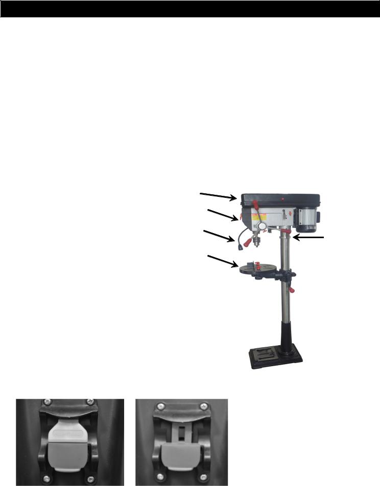
1. |
Head assembly |
||
|
|||
2. |
Column Assembly |
6 |
|
3. Table |
|||
4. |
Base |
2 |
|
5. ON/OFF Switch |
3 |
||
6. Flexible Lamp |
|||
To turn on drill press, lift paddle switch from bottom.
To turn off drill press, push paddle switch down.
To prevent unauthorized use, remove the center key from the switch. Figure 1B and 1C
Drill press cannot be turned ON if key is not inserted.
4 
FIGURE 1
FIGURE 1B |
|
FIGURE 1C |
|
|
|
6
CARTON CONTENTS
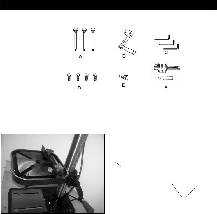
B. Accessories (in one separate box)
See Fig.2
A.Feed handles
B.Crank handle
C.Hex wrenches
D.Hex bolts
E.Chuck key
F.5/8-inch Chuck and chuck removal tool
G Table fence set
Table Fence
Use the supplied hardware to attach the fence to the table as shown in the picture below. Use the fence to align the workpiece and provide a backstop for secure drilling.
NOTE: Table pictured is different shape than equipped with product. Fence attaches through slots in the same manner.
Fence
G
Wingnuts
7

ASSEMBLY
1.Column support to base
1.2Place the column on the base, aligning the holes in the column support with the holes in the base.
1.3Locate the four long hex bolts from the loose parts bag.
1.4Place a bolt in each hole through the column support and the base. Tighten with an adjustable wrench. See Fig. 1
2.Installing the Table
2.1Loosen set screw (1). Remove rack (2) and retaining ring (3) from column (4). Fig. 2A
2.2Place rack inside table assembly bracket (5) with large, unmachined portion of rack to the top. Slide rack into slot in bracket so that teeth of rack engage pinion gear in bracket. Fig. 2A
2.3Slide table assembly with rack over column. Place bottom end of
2.4Slide rack retaining ring (3) over column with beveled edge down. Position ring against top of rack so that rack is in beveled edge of ring. Fig. 2B Secure ring with hex wrench (1). Fig. 2C
2.5Rotate table assembly around column. Adjust rack retaining ring as necessary to prevent binding of rack.
2.6Attach crank handle (6) to shaft (7), rotate to remove slack, and shoulder crank handle against table bracket. Secure handle with screw. Fig. 2B
2.7Tighten table bracket locking handle (9) to secure table assembly.
Fig. 3
|
|
2A |
|
|
|
2B |
||||
|
Figure |
|
Figure |
|||||||
|
|
|
|
|
|
|
|
|
|
|
|
|
|
|
|
|
|
|
|
|
|
|
|
|
|
|
|
|
|
|
|
|
|
|
|
|
|
|
|
|
|
|
|
Figure 1
Figure 2C
Figure 3
3.Installing head assembly
3.1.Carefully lift the head above the column and slide it onto the column.
Make sure the head slides down over the column as far as possible.
Align the head with the base.
3.2.Using the hex wrench, tighten the head lock set screws.
See Fig. 4
4.Installing feed handles
4.1.Locate the three feed handles in the loose parts box.
4.2.Screw the feed handles into the threaded holes in the hub. Tighten.
See Fig. 5.
Figure 4
8 |
Figure 5 |
ASSEMBLY
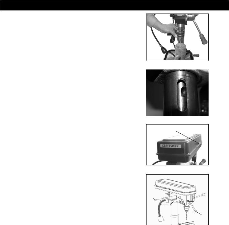
5. Installing the chuck
WARNING: Before any assembly of the chuck and arbor to the drill press head, clean all mating surfaces with a non-petroleum based product; such as alcohol or lacquer thinner. Any oil or grease used in the packing of these parts must be removed; otherwise the chuck may come loose during operation.
5.1Open the jaws of the chuck by rotating the chuck sleeve clockwise. To prevent damage, make sure the jaws are completely receded into the chuck.
5.2Push the chuck shaft into the spindle.
5.3.Use a wooden mallet to firmly tap the chuck securely into place in the spindle. See Fig. 6.
NOTE: To remove chuck perform the following:
-Rotate the chuck sleeve clockwise until the jaws recede completely into the chuck.
-Lower the spindle as far as it will go to reveal the spindle slot. See Fig.6A
-Raise the table to a position just below the the chuck.
-Insert the tip of the chuck removal tool into the spindle slot above the tip of the chuck shaft.
-Tap on the blunt end of the wedge tool until the chuck releases from the spindle.
6.Install knob for the head assembly lid. Fig. 7
7.Flexible lamp
Install the flexible lamp
7.1.Connect the lamp plug contact to the power source plug contact in the drill head as shown.
7.2.Use four pan head screws to install the lamp assembly to the drill head as shown.
7.3.Turn on the flexible lamp switch to check the lighting. Fig. 8
Figure 6
Figure 6A
Knob
Figure 7
Pan head screw
Plug contact
Flex lamp switch
Figure 8
9
ADJUSTMENT
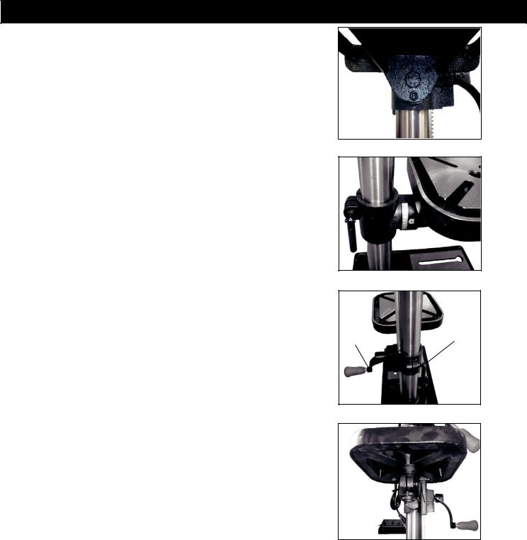
1. Table adjustment
A.Tilting adjustment:
-On underside of table support bracket, loosen the nut (right-handed rotation) with an open end wrench and back out the threaded pin. Loosen large hex head bolt. See Fig.9
-Rotate table to desired angle right or left. Use bevel scale for precise setting.
See Fig.10
-Tighten hex head bolt to secure table tilt. Threaded pin should not come into the hole when table is tilted.
-To return table to level, loosen large hex head bolt. Rotate table to level position. Make nut and thread pin end at the same level position, then push the thread pin into the hole. Securely tighten large hex head bolt.
B.Height adjustment
Loosen the clamp bolt then adjust the table to your desired position by turning the table bracket crank handle. See Fig. 11
C.Swing Adjustment 360°
Loosen the table swing locking handle, then swing table to desired position and retighten the handle. See Fig. 12
Figure 9
Figure 10
Crank |
Clamp bolt |
handle |
Figure 11
Table Swing Locking
Handle
Figure 12
10
ADJUSTMENT
WARNING: To prevent personal injury, always disconnect the plug from the power source when making any adjustment.
2. Feed Depth Adjustment
The depth gauge is located on the feed handle hub. Use the depth gauge to accurately and consistently set the required drilling depth. Loosen the depth stop fixing screw, set the depth stop as required and
subsequently re-tighten the fixing screw.
3. Speed Adjustment
This drill press has 16 speeds shown in the speed label located on the underside of the head assembly lid. To change the speed, loosen the belt tension lock knob on each side of the head. Then use the adjustment lever to draw the motor mounting plate toward the front end of the drill head. Next, change the belt locations on the pulleys.
Tighten the belts by pushing the adjustment lever towards the rear of the drill head and locking the belt tension knobs. See Fig.13 and Fig.13A
4. Spindle Spring Adjustment
The spindle return spring may need adjustment if the tension causes the spindle to return too rapidly or too slowly.
4.1Lower the table for additional clearance.
4.2Place a screwdriver in the lower front notch (1) of the spring cap (2). Hold it in place while loosening and removing only the outer lock nut (3).
4.3With the screwdriver still engaged in the notch loosen the inner
nut (4) just until the notch (5) disengages from the boss (6) on the drill
press head.
CAUTION: DO NOT REMOVE THIS INNER NUT, because the spring will forcibly unwind.
4.4Carefully turn the spring cap (2) counterclockwise with the screwdriver, engaging the next notch.
4.5Lower the spindle to the lowest position by rotating the feed handle in a counterclockwise direction while holding the spring cap (2) in position.
4.6If the spindle moves up and down as easily as you desire, tighten the inner nut (4) with the adjustable wrench. If too loose, repeat steps 2 through 4 to tighten. If too tight, reverse steps 3 and 4. DO NOT OVERTIGHTEN and restrict spindle movement.
4.7Replace the lock nut (3) and tighten against the inner nut (4) to prevent the inner nut from reversing. See Fig.14 and Fig. 14A
5.SPINDLE
Rotate the feed handles counterclockwise to lower spindle to its lowest position. Grasp the spindle and attempt to move it back and forth. If there is play, do the following:
5.1Loosen the spring cap lock nut (1).
5.2Turn the screw (2) clockwise to eliminate the play, but without obstructing the upward movement of the spindle.
5.3Tighten the lock nut (1). See Fig. 15
Figure 12
Figure 13
Adjustment Lever
Lock Knob 
Figure 13A
Figure 14
Spring Cap
Figure 14A
1
2
Figure 15
11
 Loading...