


113196221
S Save This Manual'_
For Future Reference
owner's
manual
MODEL NO.
113.196221
113.196321
SAW WITHLEGS
or
113.196421
CONTRACTOR'S SAW
Serial
Number.
Model and serial numbers
may be found at the front
of the base.
You should record both
model and serial number in
a safe place for future use.
_'_E_A/F_S/ I:RI1FT$MRN
10-1NCH RADIAL SAW
FORYOUR
SAFETY:
• assembly
READ ALL
• operating
INSTRUCTIONS
CAREFULLY
• repair parts
\
Sears Roebuck and Co., Hoffman Estates, IL 60179 U.S.A.
Part No. SP5667 Printed in U.S.A.
Table of Contents
Section Title ................................................................................ Page
Safety ........................................................................................................................ 3
Introduction ............................................................................................................ 12
Assembly ................................................................................................................ 12
Adjustments ............................................................................................................ 19
Alignment ............................................................................................................... 28
Controls .................................................................................................................. 37
Electrical Connections ........................................................................................... 42
Crosscutting ............................................................................................................ 45
Ripping ................................................................................................................... 49
Cutting Aides ......................................................................................................... 58
Accessories ............................................................................................................. 61
Maintenance ........................................................................................................... 63
Troubleshooting ..................................................................................................... 65
Repair Parts ............................................................................................................ 70
FULL ONE YEAR WARRANTY ON CRAFTSMAN STATIONARY TOOL
If, this stationary tool fails due to a defect in material or workmanship within one
year from the date of purchase, CONTACT THE NEAREST SEARS SERVICE
CENTER IN THE UNITED STATES and Sears will repair it, free of charge. This
warranty applies only while this product is in the United States.
If this Radial Saw is used for commercial or rental purposes, this warranty will
apply for ninety days from the date of purchase.
This warranty gives you specific legal rights, and you may also have other rights
which vary from state to state.
SEARS, ROEBUCK AND CO., DEPT 817WA, Hoffman Estates, IL 60179 U.S.A.
Safety
This manual has safety information and
instructions to help users eliminate or reduce
the risk of accidents and injuries, including:
i. Severe cuts, and loss of fingers or other
body parts due to contact with the blade.
2. Eye impact injuries, and blindness, from
being hit by a thrown workpiece, workpiece
chips or pieces of blade.
3. Bodily impact injuries, broken bones, and
internal organ damage from being hit by a
thrown workpiece
4. Shock or electrocution
5. Bums.
M_or Hazards
Three major hazards are associated with
using the radial arm saw for ripping. They
are outfeed zone hazard, kickback, and
wrong way feed.
This section only briefly explains these haz-
ards. Read the ripping and crosscutting safe-
ty sections for more detailed explanations of
these and other hazards.
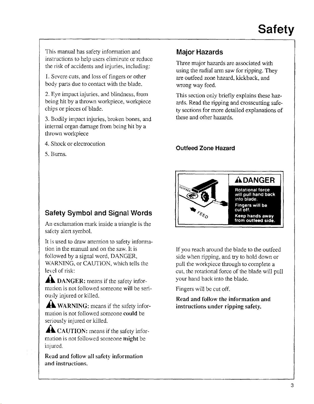
Outfeed Zone Hazard
Ai_kDANGER
Safety Symbol and Signal Words
An exclamation mark inside a triangle is the
safety alert symbol.
It is used to draw' attention to safety info_Tna-
tion in the manual and on the saw. It is
followed by a signal word, DANGER,
WARNING, or CAUTION, which tells the
level of risk:
,_ DANGER: means if the safety infor-
mation is not followed someone will be seri-
ously injured or killed.
A
,_ WARNING: means if the safety infor-
mation is not followed someone could be
seriously injured or killed.
A
,_ CAUTION: means if the safety infor-
mation is not followed someone might be
inj are&
Read and follow all safety information
and instructions.
If you reach around the blade to the outfeed
side when ripping, and try to hold down or
pull the workpiece through to complete a
cut, the rotational force of the blade will pull
your hand back into the blade.
Fingers will be cut off.
Read and follow the information and
instructions under ripping safety.
Safety
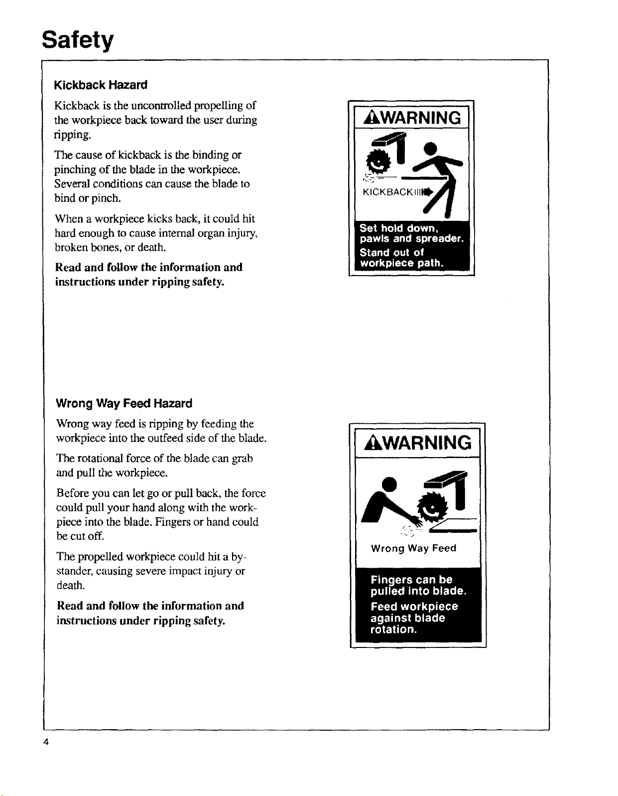
Kickback Hazard
Kickback is the uncontrolled propelling of
the workpiece back toward the user during
ripping.
The cause of kickback is the binding or
pinching of the blade in the workpiece.
Several conditions can cause the blade to
bind or pinch.
When a workpiece kicks back, it could hit
hard enough to cause internal organ injury,
broken bones, or death.
Read and follow the information and
instructions under ripping safety.
WARNING
KICKBACKIII_
Wrong Way Feed Hazard
Wrong way feed is ripping by feeding the
workpiece into the outfeed side of the blade.
The rotational force of the blade can grab
and pull the workpiece.
Before you can let go or pull back, the force
could pull your hand along with the work-
piece into the blade. Fingers or hand could
be cut off.
The propelled workpiece could hit a by-
stander, causing severe impact injury or
death.
Read and follow the information and
instructions under ripping safety.
WARNING
Wrong Way Feed
4
Guard Function and Features
The guard is a very important safety feature,
designed to reduce the risk of injury associ-
ated with blade contact. Install the guard
correctly. Follow the specific instructions
in the ripping and crosscutting sections to
set and use the guard correctly for each
ty pe of cut.
Guard Features Include:
Safety
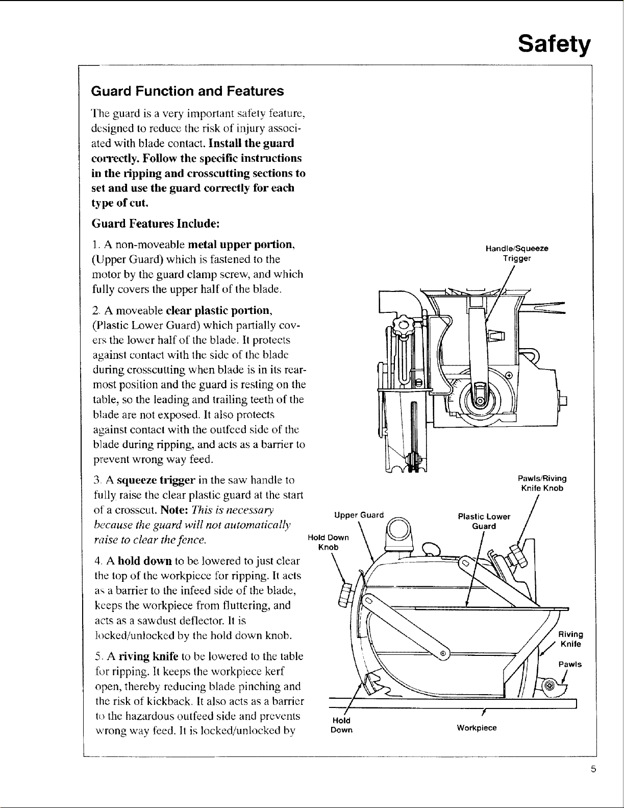
1 A non-moveable metal upper portion,
(Upper Guard) which is fastened to the
motor by the guard clamp screw, and which
fully covers the upper half of the blade.
2. A moveable clear plastic portion,
(Plastic Lower Guard) which partially cov-
ers the lower half of the blade. It protects
against contact with the side of the blade
during crosscutting when blade is in its rear-
most position and the guard is resting on the
table, so the leading and trailing teeth of the
blade are not exposed. It also protects
against contact with the outfced side of the
blade during ripping, and acts as a barrier to
prevent wrong way feed.
3 A squeeze trigger in the saw handle to
rally raise the clear plastic guard at the start
of a crosscut. Note: 1"his' is necessary
because the guard will not automatically
raise to clear the fence.
4. A hold down to be lowered to just clear
the top of the workpiece for ripping. It acts
a_ a barrier to the infeed side of the blade,
keeps the workpiece from fluttering, and
acts as a sawdust deflector. It is
locked/unlocked by the hold down knob.
5 A riving knife to be lowered to the table
for ripping. It keeps the workpiece kerf
open, thereby reducing blade pinching and
the risk of kickback. It also acts as a barrier
to the hazardous outfeed side and prevents
wrong way feed. It is locked/unlocked by
Upper Guard
Hold Down
Knob
Hold
Down
Handle!Squeeze
Trigger
Pawls/Riving
Knife Knob
Plastic Lower
Guard
Riving
Knife
Pawls
?
Workpiece
Safety
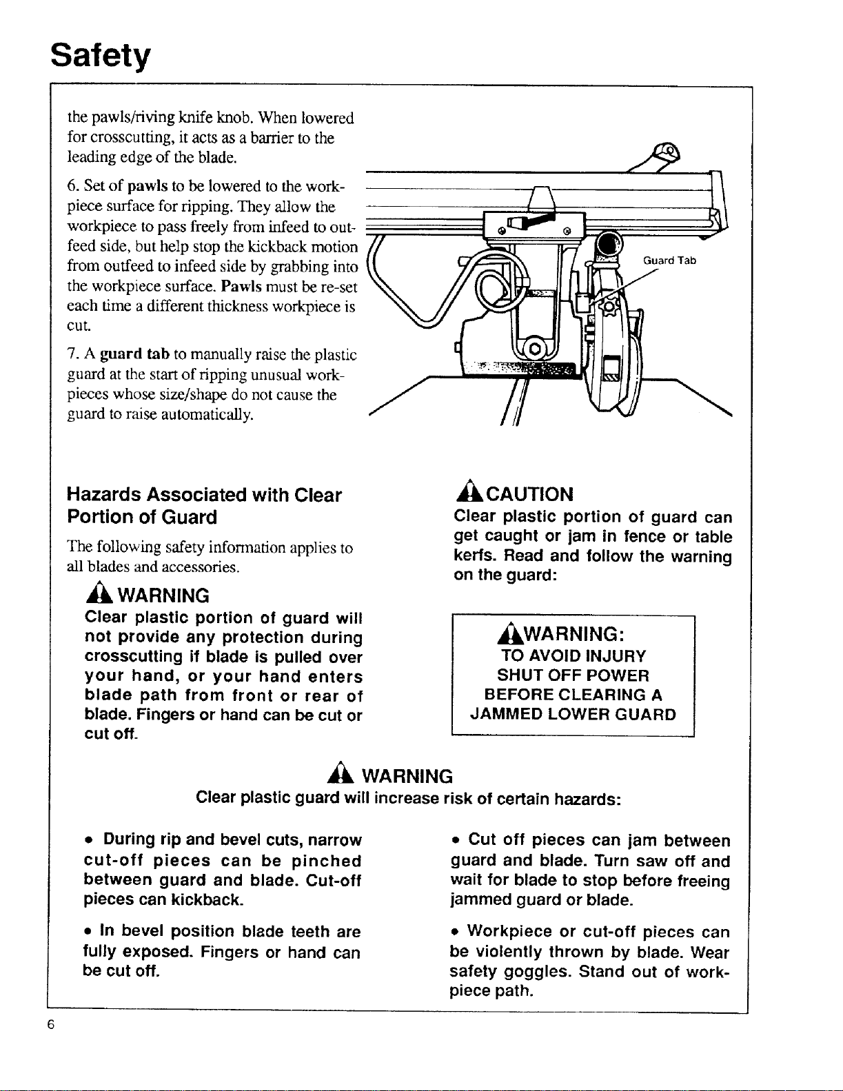
the pawls/riving knife knob. When lowered
for crosscutting, it acts as a barrier to the
leading edge of the blade.
6. Set of pawls to be lowered to the work-
piece surface for ripping. They allow the
workpiece to pass freely from infeed to out-
feed side, but help stop the kickback motion
from ouffeed to infeed side by grabbing into
the workpiece surface. Pawls must be re-set
each time a different thickness workpiece is
cut.
7. A guard tab to manually raise the plastic
guard at the start of ripping unusual work-
pieces whose size/shape do not cause the
guard to raise automatically.
Guard Tab
Hazards Associated with Clear
Portion of Guard
The following safety information applies to
all blades and accessories.
WARNING
Clear plastic portion of guard will
not provide any protection during
crosscutting if blade is pulled over
your hand, or your hand enters
blade path from front or rear of
blade. Fingers or hand can be cut or
cut off.
Clear plastic guard will increase risk of certain hazards:
• During rip and bevel cuts, narrow
cut-off pieces can be pinched
between guard and blade. Cut-off
pieces can kickback.
_CAUTION
Clear plastic portion of guard can
get caught or jam in fence or table
kerfs. Read and follow the warning
on the guard:
,_WARNING:
TO AVOID INJURY
SHUT OFF POWER
BEFORE CLEARING A
JAMMED LOWER GUARD
WARNING
• Cut off pieces can jam between
guard and blade. Turn saw off and
wait for blade to stop before freeing
jammed guard or blade.
• In bevel position blade teeth are
fully exposed. Fingers or hand can
be cut off.
• Workpiece or cut-off pieces can
be violently thrown by blade. Wear
safety goggles. Stand out of work-
piece path.
Safety Instructions
Read and follow all safety instructions.
Personal Safety Instructions
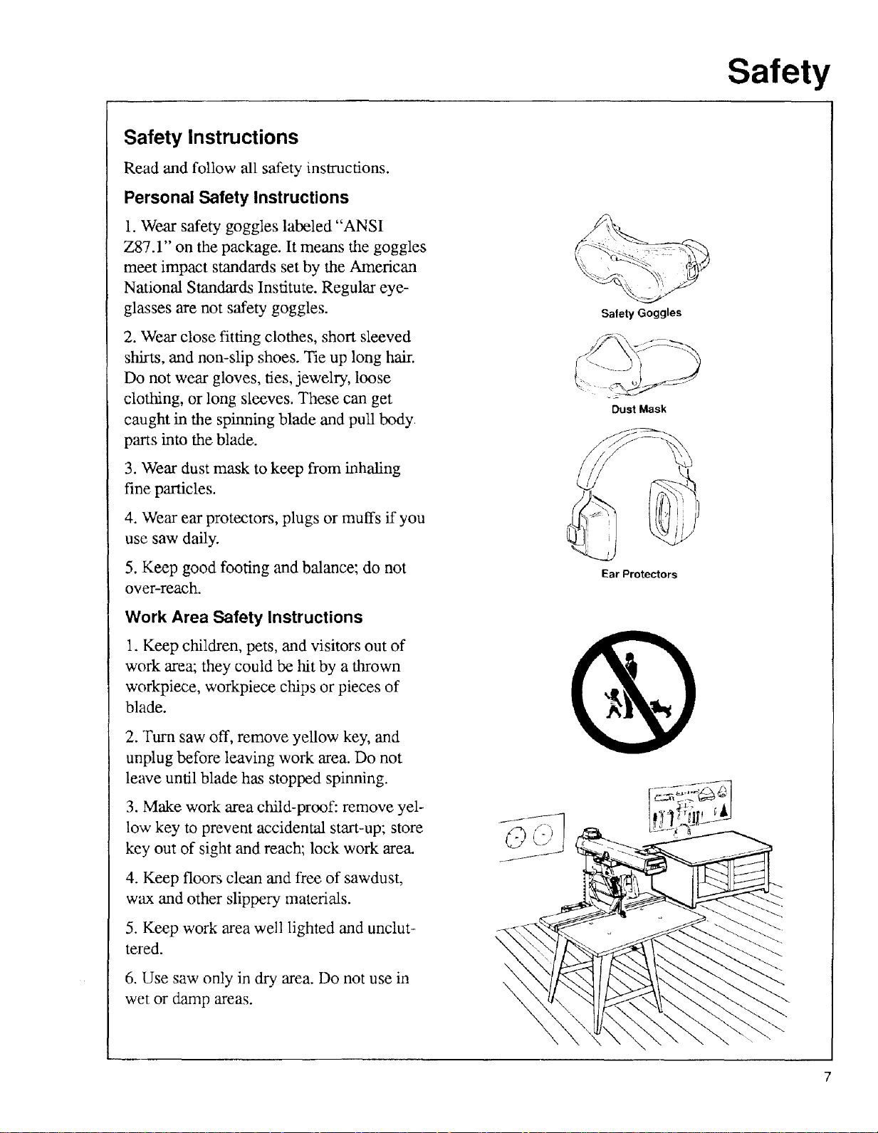
1. Wear safety goggles labeled "ANSI
Z87.1" on the package. It means the goggles
meet impact standards set by the American
National Standards Institute. Regular eye-
glasses are not safety goggles.
2. Wear close fitting clothes, short sleeved
shirts, and non-slip shoes. Tie up long hair.
Do not wear gloves, ties, jewelry, loose
clothing, or long sleeves. These can get
caught in the spinning blade mad pull body
parts into the blade.
3. Wear dust mask to keep from inhaling
fine particles.
Safety
Safety Goggles
Dust Mask
4. Wear ear protectors, plugs or muffs if you
use saw daily.
5. Keep good footing and balance; do not
over-reach.
Work Area Safety Instructions
1. Keep children, pets, and visitors out of
work area; they could be hit by a thrown
workpiece, workpiece chips or pieces of
blade.
2. Turn saw off, remove yellow key, and
unplug before leaving work area. Do not
leave until blade has stopped spinning.
3. Make work area child-proof: remove yel-
low key to prevent accidental start-up; store
key out of sight and reach; lock work area.
4. Keep floors clean and free of sawdust,
wax and other slippery materials.
5. Keep work area well lighted and unclut-
tered.
6. Use saw only in dry area. Do not use in
wet or danap areas.
Ear Protectors
\
\
\
Safety
Saw Safety Instructions
1. Use guard, pawls and riving knife accord-
ing to instructions. Keep them in working
order.
2. Routinely check saw for broken or dam-
aged parts. Repair or replace damaged parts
before using saw. Check new or repaired
parts for alignment, binding, and correct
installation.
3. Unplug saw before doing maintenance,
making adjustments, correcting alignment,
or changing blades.
4. Do not force saw. Use saw, blades and
accessories only as intended.
5. Have yellow key out and saw switched off
before plugging in power cord.
6. Before turning on saw, clear table of all
objects except workpiece to be cut and nec-
essary fixtures, clamps, or feather-boards.
7. If blade jams, turn saw off immediately,
remove yellow key, the free blade. Do not
try to free blade with saw on.
8. Turn saw off if it vibrates too much or
makes an odd sound. Correct any problem
before restarting saw.
9. Do not layout, assemble, or setup work
with saw on, or while blade is spinning.
10. Keep saw table clean.
11. Store items away from saw. Do not
climb on saw or stand on saw table to reach
items because saw can tip over.
Workpiece Safety Instructions
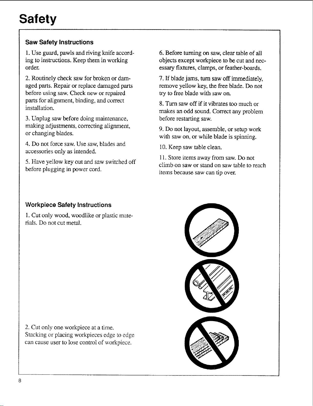
1. Cut only wood, woodlike or plastic mate-
fins. Do not cut metal.
2. Cut only one workpiece at a time.
Stacking or placing workpieces edge to edge
can cause user to lose control of workpiece.
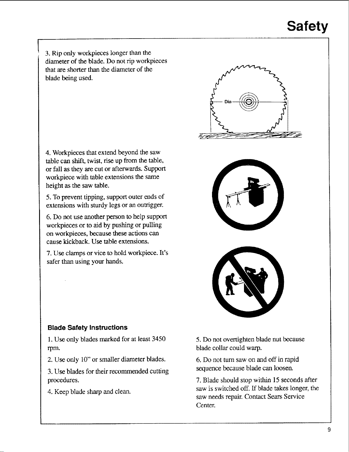
3. Rip only workpieces longer than the
diameter of the blade. Do not rip workpieces
that are shorter than the diameter of the
blade being used.
4. Workpieces that extend beyond the saw
table can shift, twist, rise up from the table,
or fall as they are cut or afterwards. Support
workpiece with table extensions the same
height as the saw table.
Safety
5. To prevent tipping, support outer ends of
extensions with sturdy legs or an outrigger.
6. Do not use another person to help support
workpieces or to aid by pushing or pulling
on workpieces, because these actions can
cause kickback. Use table extensions.
7. Use clamps or vice to hold workpiece. It's
safer than using your hands.
Blade Safety Instructions
1. Use only blades marked for at least 3450
rpm.
2. Use only 10" or smaller diameter blades.
3. Use blades for their recommended cutting
procedures.
4. Keep blade sharp and clean.
5. Do not overtighten blade nut because
blade collar could warp.
6. Do not turn saw on and off in rapid
sequence because blade can loosen.
7. Blade should stop within 15 seconds after
saw is switched off. ff blade takes longer, the
saw needs repair. Contact Sears Service
Center.
Safety
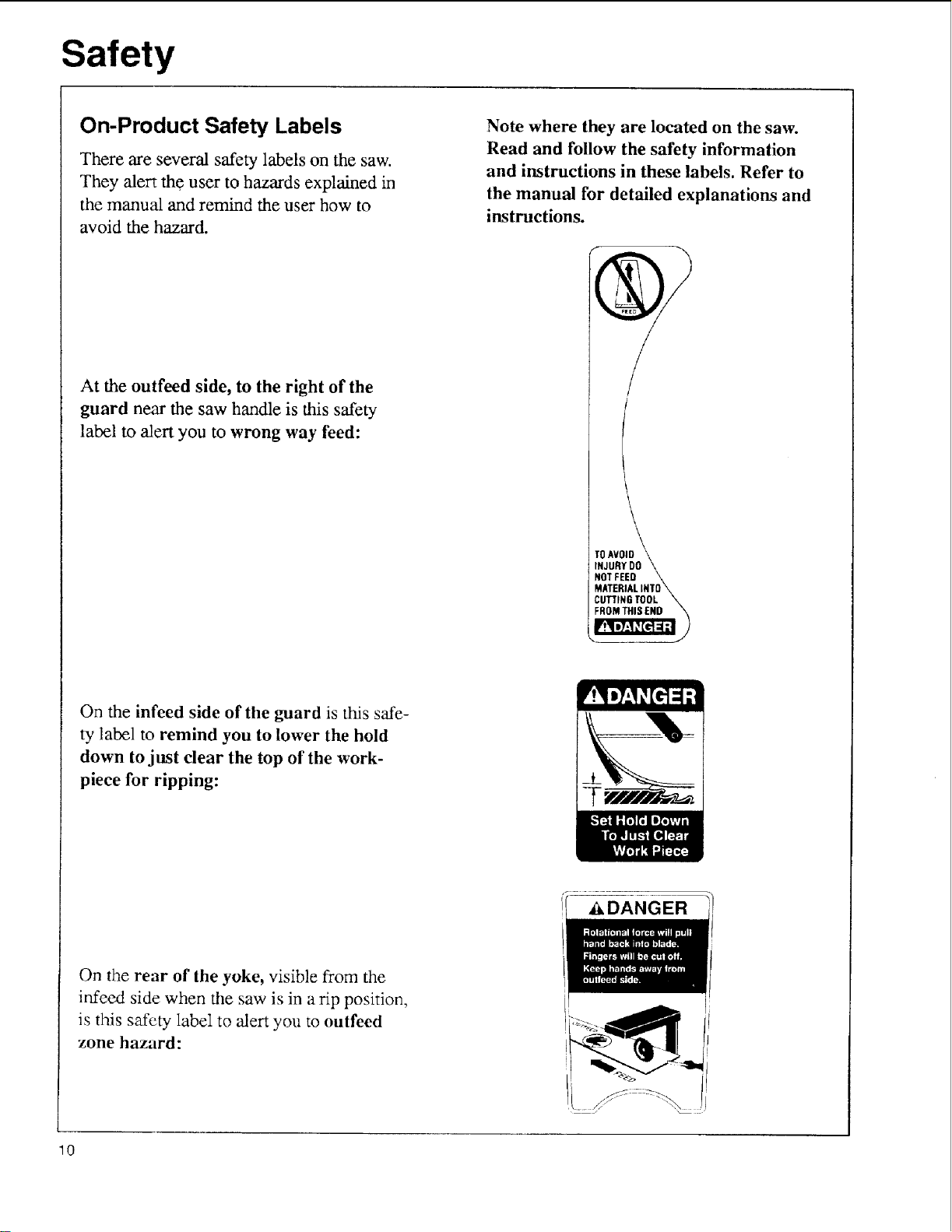
On-Product Safety Labels
There are several safety labels on the saw.
They alert the user to hazards explained in
the manual and remind the user how to
avoid the hazard.
At the outfeed side, to the right of the
guard near the saw handle is this safety
label to alert you to wrong way feed:
Note where they are located on the saw.
Read and follow the safety information
and instructions in these labels. Refer to
the manual for detailed explanations and
instructions.
/
I
TOAVOID \\
INJURYDO \,.
NOT FEED \
MATERIALINTO\
I CUTTINGTOOL
On the infeed side of the guard is this sde-
ty label to remind you to lower the hold
down to just clear the top of the work-
piece for ripping:
On the rear of the yoke, visible from the
infeed side when the saw is in a rip position,
is this safety label to alert you to outfeed
zone hazard:
10
_DANGER
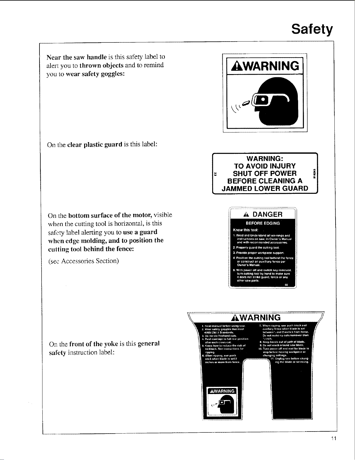
Near the saw handle is dais safety label to
"alert you to thrown objects and to remind
you to wear safety goggles:
On the clear plastic guard is this label:
Safety
,&WARNING
TO AVOID INJURY
=
SHUT OFF POWER !
BEFORE CLEANING A
JAMMED LOWER GUARD ,,
WARNING: I
On the bottom surface of the motor, visible
when the cutting tool is horizontal, is this
safety label alerting you to use a guard
when edge molding, and to position the
culling tool behind the fence:
(see Accessories Section)
On the front of the yoke is dais general
safety instruction label:
DANGER
,_WARNING
11
Assembly
Introduction
In order to get the most enjoyment out of your radial saw it is important that the machine by properly
assembled, adjusted, and aligned. This procedure, although not difficult, takes time; perhaps eight
hours or longer for the inexperienced user. However, after this initial set-up a weekly tune-up can be
completed in approximately ten minutes by checking the alignment and only adjusting those settings
which are incorrect.
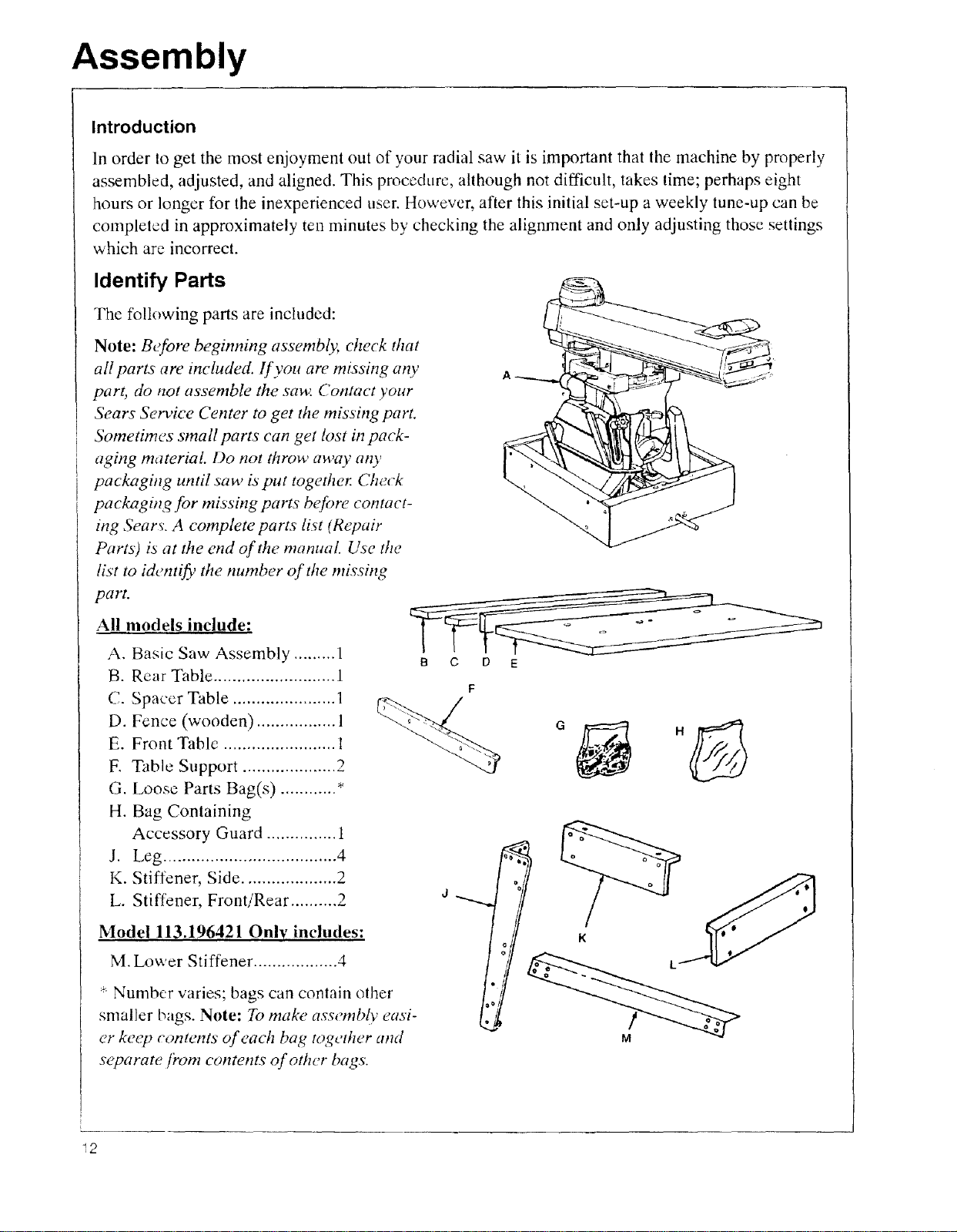
Identify Parts
The following parts are included:
Note: Before beginning assembly, check that
all parts are included. If you are missing any
part, do not assemble the saw Contact your
Sears Service Center to get the missing part.
Sometimes small parts can get lost in pack-
aghzg material Do not throw away arty
packagi,g until saw is put together. Check
pacl_zgh_g for missh_g parts before contact-
ing Sears. A complete parts list (Repair
Parts) is at the end of the manual. Use the
list to identify the number of the missing
part.
All models include:
A. Basic Saw Assembly ......... 1
B. Rear Table .......................... 1
C. Spacer Table ...................... 1
D. Fence (wooden) ................. 1
E. Front Table ........................ 1
F. Table Support .................... 2
G. Loose Parts Bag(s) ............ *
H. Bag Containing
Accessory Guard ............... 1
J. Leg ..................................... 4
K. Stiffener, Side .................... 2
L. Stiffener, Front!Rear .......... 2
Model 113.196421 Only includes:
M. Lower Stiffener .................. 4
* Number varies; bags can contain other
smaller bags. Note: To make assembly easi-
er keep contents of each bag tog_¢ther and
separate from contents of other bags.
B C D
F
d
K L
_2
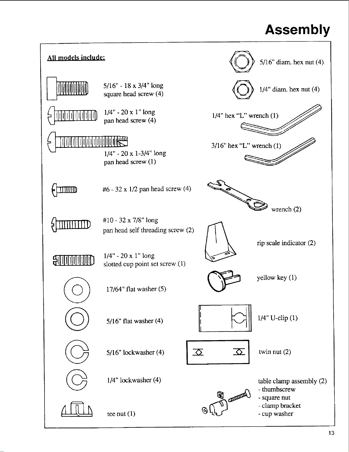
All models include:
5/16" - 18 x 3/4" long
square head screw (4)
Assembly
5/16" diam. hex nut (4)
1/4" diam. hex nut (4)
_llqqillllll[tllllliO1/4"-20x 1"long
pan head screw (4)
_ IillJllilll_liH_l_l_lilllllil,lt_
1/4" - 20 x 1-3/4" long
pan head screw (1)
#6 - 32 x 1/2 pan head screw (4)
#10 - 32 x 7/8" long
_lllllllllll)
_illllllllltlllllil7
pan head self threading screw (2)
1/4" - 20 x 1" long
slotted cup point set screw (1)
1/4" hex "_
3/16" hex "L'_
wrench (2)
rip scale indicator (2)
yellow key (1)
©
©
©
17/64" fiat washer (5)
5/16" flat washer (4)
5/16" lockwasher (4)
1/4" lockwasher (4)
tee nut (1)
i
1/4"U-clip (1)
--6"
] twin nut (2)
table clamp assembly (2)
- thumbscrew
- square nut
- clamp bracket
- cup washer
13

Assembly
C)
@
crank
1/4" diam. x 5/8" long
truss head screw (24)
(40 for 113.196421)
leveling foot (4)
3/8" diatn, hex nut (8)
5/16" diam. hex nut
(4)
©
@
@
arm cap
1/4" external tooth
lockwasher (24)
(40 for 113.196421)
5/16" diam. external
lockwasher (4)
11/32" x 11/16" x 1/16"
washer (8)
1/4" diam. hex nut
©
(40 for 113.196421)
Tools needed for Assembly and Alignment
7116" Wrench
@' _ 1,'2" Wrench
@ ........ @ 9/16"Wrench
Small Hammer
(24)
15/16" Wrench
5/16" diam. x 5/8" long
hex head screw (4)
Wrench
Pliers Phillips Screwdriver
Pencil
I
Medium Screwdriver
Framing Square
14
Assembly
_k WARNING
Plugging in saw during assembly
could result in electrical shock, or
severe cuts from contact with spin-
ning blade.
Do not plug in saw at any time dur-
ing assembly.
Plug in saw only when it is to be
used.
Assembly Steps
It is important for your safety and to get
accurate cuts that you put the saw together
according to these instructions.
Fol!ow these steps in order.
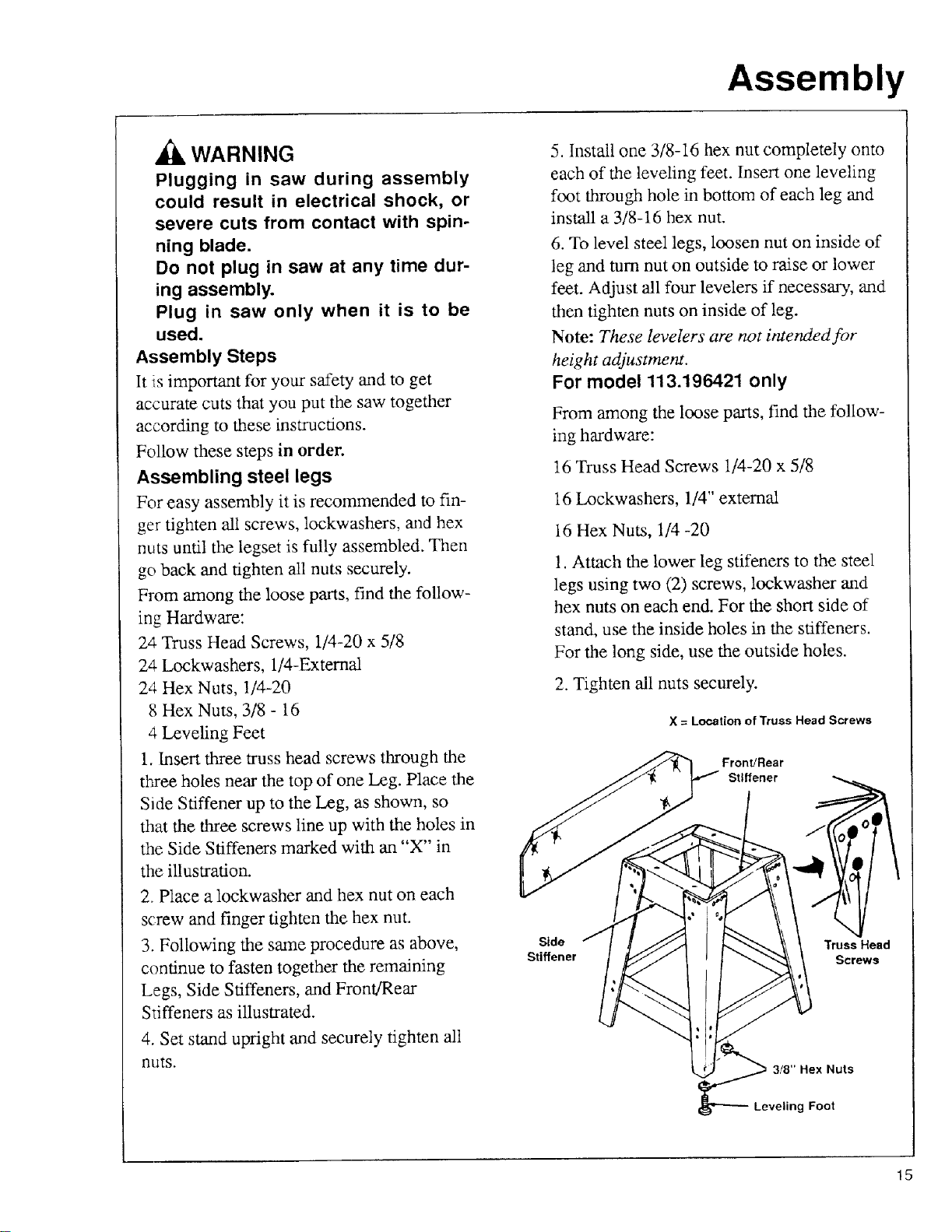
Assembling steel legs
For easy assembly it is recommended to fin-
ger tighten all screws, lockwashers, and hex
nuts until the legset is fully assembled. Then
go back and tighten all nuts securely.
From among the loose parts, find the follow-
ing Hardware:
24 Truss Head Screws, 1/4-20 x 5/8
24 Lockwashers, 1/4-External
24 Hex Nuts, !/4-20
8 Hex Nuts, 3/8 - 16
4 Leveling Feet
1. Insert three truss head screws through the
three holes near the top of one Leg. Place the
Side Stiffener up to the Leg, as shown, so
that the three screws line up with the holes in
the Side Stiffeners marked with an "X" in
the illustration.
2. Place a lockwasher and hex nut on each
screw and finger tighten the hex nut.
3. Following the same procedure as above,
continue to fasten together the remaining
Legs, Side Stiffeners, and Front/Rear
Stiffeners as illustrated.
5. Install one 3/8-16 hex nut completely onto
each of the leveling feet. Insert one leveling
foot through hole in bottom of each leg and
install a 3/8-16 hex nut.
6. To level steel legs, loosen nut on inside of
leg and turn nut on outside to raise or lower
feet. Adjust all four levelers if necessary, and
then tighten nuts on inside of leg.
Note: These levelers" are not intended for
height adjustment.
For model 113.196421 only
From among the loose parts, find the follow-
ing hardware:
16 Truss Head Screws 1/4-20 x 5/8
16 Lockwashers, 1/4" external
16 Hex Nuts, 1/4 -20
!. Attach the lower leg stifeners to the steel
legs using two (2) screws, lockwasher and
hex nuts on each end. For the short side of
stand, use the inside holes in the stiffeners.
For the long side, use the outside holes.
2. Tighten all nuts securely.
X = Location of Truss Head Screws
Front/Rear
Stiffener
Side Truss Head
Stiffener Screws
4. Set stand upright and securely tighten all
nuts.
3/8" Hex Nuts
Leveling Foot
15
Assembly
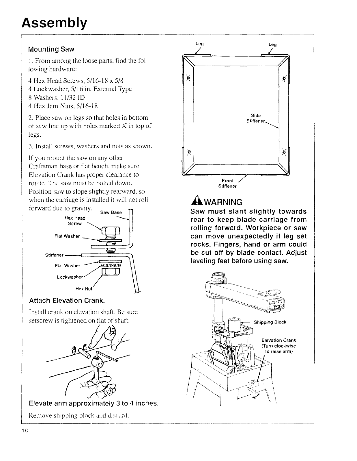
Mounting Saw
1. From _mlong tile loose p'-w'ts,find the fol--
lowing hmdware:
4 ttex tlead Screws, 5/16-18 x 5/8
4 Lockwasher, 5/16 in. External Type
8 Washers, 11/32 ID
4 Hex Jam Nuts, 5/16-t8
2. Place saw on legs so that holes in bottom
of saw line up with holes marked X in top of
legs.
3. Install screws, washers and nuts as shown.
If you mount the saw on any other
Craftsman base or Slat bench, make sure
Elevation Crm_k has proper clearance to
rotate. The saw must be bolted down.
Position saw to slope slightly rearward, so
when tile carriage is installed it will not roll
forward due to gravity. SawBase
Hex Head _ I
Stiffener
Flat Washer
Leg Leg
/ , ,/
%, //
Front /
Sliffener
_WARNING
Saw must slant slightly towards
rear to keep blade carriage from
rolling forward. Workpiece or saw
can move unexpectedly if leg set
rocks. Fingers, hand or arm could
be cut off by blade contact. Adjust
leveling feet before using saw.
Lockwasher
Hex Nut
Attach Elevation Crank.
Install crank on elevation shaft. Be sure
setscrew is tightened on flat of shaft.
Elevate arm approximately 3 to 4 inches.
Remove shipping block mid discurd.
16
Shipping Block
Elevation Crank
(Turn clockwise
to raise arm)
\
\
\
\
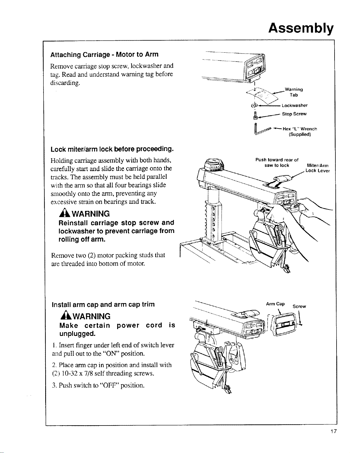
Attaching Carriage - Motor to Arm
Remove carriage stop screw, lockwasher and
tag. Read and understand warning tag before
discarding.
Assembly
Warning
Tab
(_j_ Lockwasher
_,.......,._-_ Stop Screw
Lock miter/arm lock before proceeding.
Holding carriage assembly with both hands,
carefully start and slide the carriage onto the
tracks. The assembly must be held parallel
with the arm so that all four bearings slide
smoothly onto the arm, preventing any
excessive strain on bearings and track.
WARNING
Reinstall carriage stop screw and
Iockwasher to prevent carriage from
rolling off arm.
Remove two (2) motor packing studs that
are threaded into bottom of motor.
_ "'-'- Hex "L" Wrench
Push toward rear of
saw to lock
(Supplied)
Miter/Arm
Lever
Install arm cap and arm cap trim
,_WARNING
Make certain power cord is
unplugged.
1 Insert finger under left end of switch lever
and pull out to the "ON" position.
2 Place arm cap in position and install with
(2) 10-32 x 7/8 self threading screws.
3. Push switch to "OFF" position.
Arm Cap
Screw
17
Assembly
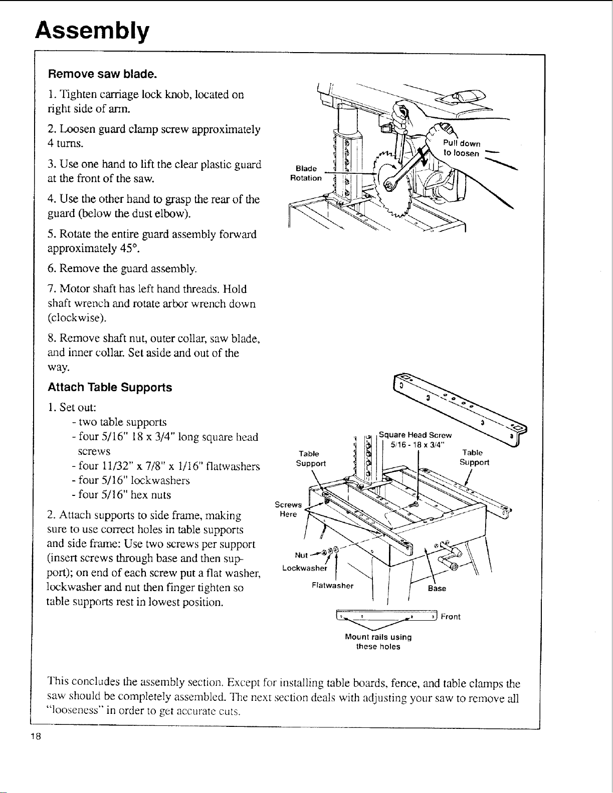
Remove saw blade.
1. Tighten carriage lock knob, located on
right side of ann.
2. Loosen guard clamp screw approximately
4 turns.
3. Use one hand to lift the clear plastic guard
at the front of the saw.
4. Use the other hand to grasp the rear of the
guard (below the dust elbow).
5. Rotate the entire guard assembly forward
approximately 45°.
6. Remove the guard assembly.
7. Motor shaft has left hand threads. Hold
shaft wrench and rotate arbor wrench down
(clockwise).
Purl down
to |oo_er}
Blade
Rotation
8. Remove shaft nut, outer collar, saw blade,
and inner collar. Set aside and out of the
way.
Attach Table Supports
1. Set out:
- two table supports
- four 5/16" 18 x 3/4" long square head
screws
- four 11/32" x 7/8" x 1/16" flatwashers
- four 5/16" lockwashers
- four 5/16" hex nuts
2. Attach supports to side frame, making
sure to use correct holes in table supports
and side frame: Use two screws per support
(insert screws through base and then sup-
port); on end of each screw put a flat washer,
lockwasher and nut then finger tighten so
table supports rest in lowest position.
SCreWS
Here
Lockwasher
Table
Support
\
Nut ""_
Flatwasher
Table
Support
Base
_] Front
Mount rails using
these holes
This concl_tdes the assembly section. Except for installing table bonds, fence, and table clamps the
saw should be completely assembled. The next section deals with adjusting your saw to remove 'all
"looseness" in order to get accurate cuts.
18
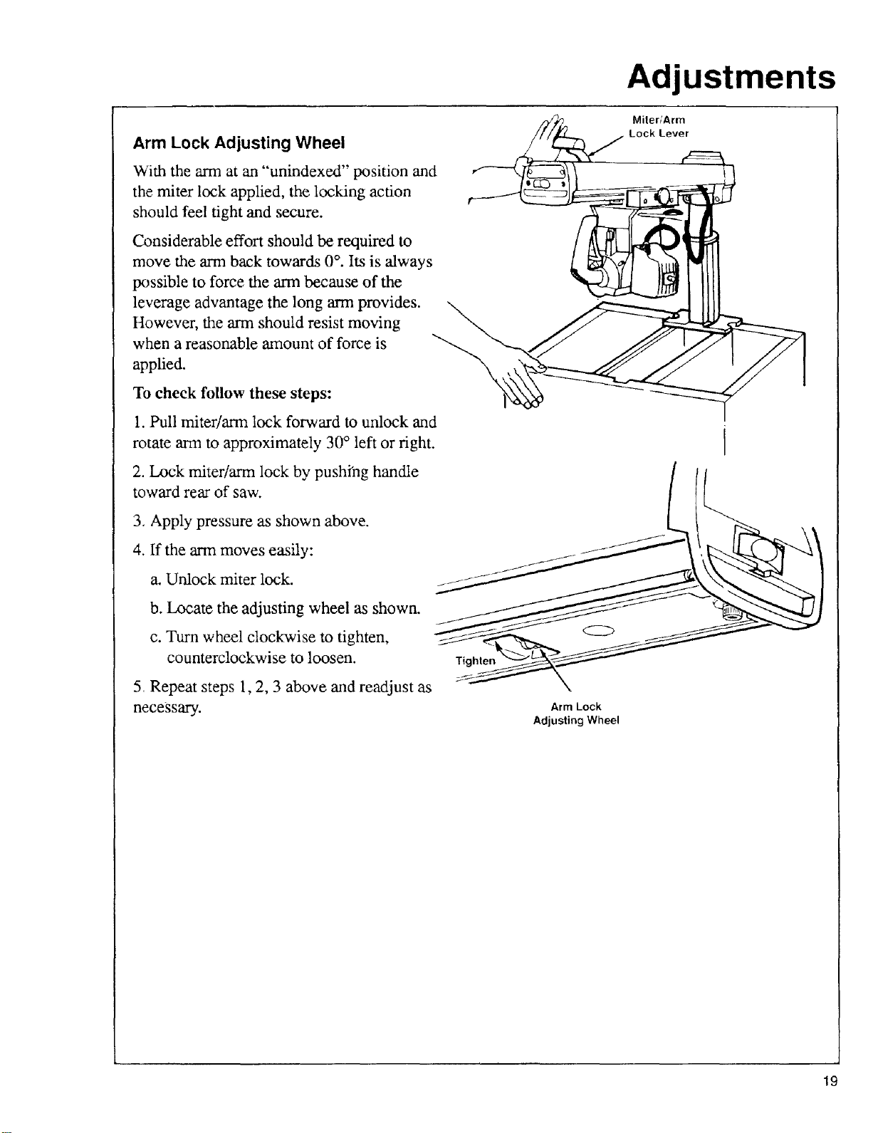
Arm Lock Adjusting Wheel
With the arm at an "unindexed" position and
the miter lock applied, the locking action
should feel tight and secure.
Considerable effort should be required to
move the ann back towards 0 °. Its is "always
possible to force the arm because of the
leverage advantage the long arm provides.
However, the arm should resist moving
when a reasonable amount of force is
applied.
To check follow these steps:
1. Pull miter/arm lock forward to unlock and
rotate ann to approximately 30° left or right.
2. Lock miter/arm lock by pushfng handle
toward rear of saw.
Adjustments
Miter/Arm
Lock Lever
3. Apply pressure as shown above.
4. If the arm moves easily:
a. Unlock miter lock.
b. Locate the adjusting wheel as shown.
c. Turn wheel clockwise to tighten,
counterclockwise to loosen.
5 Repeat steps 1, 2, 3 above and readjust as
necessary.
Arm Lock
Adjusting Wheel
19
Adjustments
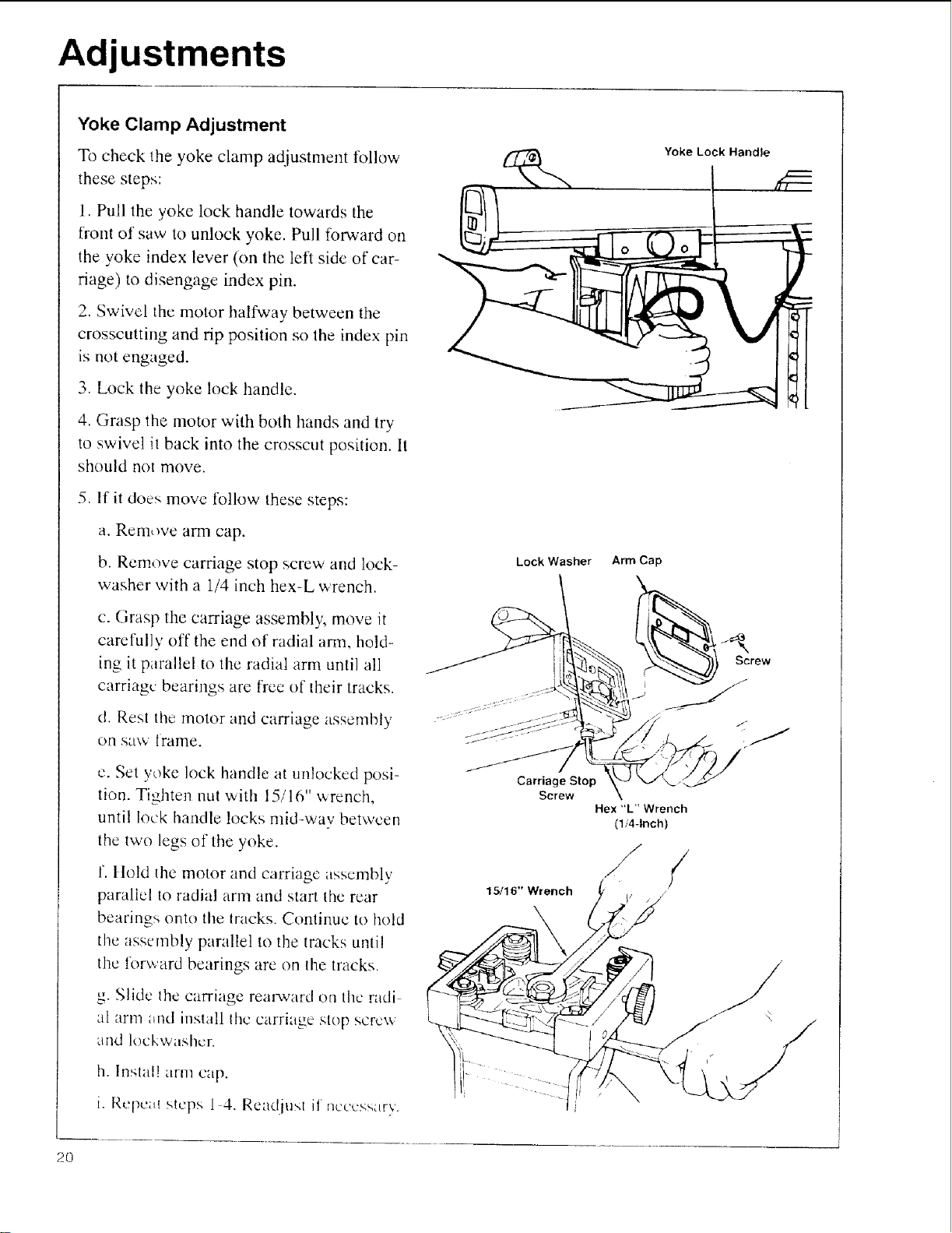
Yoke Clamp Adjustment
To check the yoke clamp adjustment follow
these steps:
1. Pull the yoke lock handle towards the
front of saw to unlock yoke. Pull forward on
the yoke index lever (on the left side of car-
riage) to disengage index pin.
2. Swivel the motor halfway between the
crosscutting and rip position so the index pin
is not engaged.
3. Lock the yoke lock handle.
4. Grasp the motor with both hands and try
to swivel it back into the crosscut position. It
should not move.
5_
If it does move tbllow these steps:
Yoke Lock Handle
a. Rein,we arm cap.
b. Remove carriage stop screw and lock-
washer with a 1/4 inch hex-L wrench.
c. Grasp the carriage assembly, move it
careful] v off the end of radial ann, hold-
ing it parallel to the radial arm until all
carriage bearings are free of their tracks.
d. Rest lhe motor and carriage assembly
on saw frame.
e. Set yoke lock handle at unlocked posi-
tion. Tighten nut with 15/16" x_,renctl,
until lock handle locks mid-way between
the two legs of the yoke.
f. ltold the motor and carriage assembly
parallel to radial arm and starl the rear
bearings onto the tracks. Continue to hold
the assembly parallel to the tracks unlil
the forward bearings are on the tracks.
Lock Washer
Carriage Stop
Screw
15/16" Wrench
Arm Cap
Screw
Hex "L" Wrench
(1i44nch)
/
/
g. Slide the carriage rearward on the radi
a[ arn-t tmlld install the carriage stop screw
and lockwashcr.
h. Instal! arm cap.
i. Rcpcul steps 1 4. Read usl if nccc_<s',try.
2O
I

Adjustments
Bevel Lock Lever
The purpose of the bevel lock lever is to
lock the motor at any angle. To check follow
these steps:
1. Unlock the bevel lock lever. Move the,
bevel index pin to the left and rotate the saw
to approximately 30 °. Lock the bevel lock
lever.
2. Use both hands as shown and try to force
the motor out of position. If the motor
moves, the bevel lock lever needs to be
tightened. On the other hand if it is extreme-
ly hard to lock the bevel lock lever it has
been over -tightened.
3. Follow these steps to adjust:
a. Remove the socket set screw with hex
wrench as shown.
b. Use the bevel lock lever as a wrench to
tighten or loosen the clamp bolt. Do not
over tighten.
c. Repeat steps 1 and 2. Re-adjust if nec-
essary
d. Replace bevel lock lever in the locked
position.
e. Tighten the set screw.
l 1
©
Bevel
Index
Pin
Bevel
Lock
Lever
\
[_ Bevel Lock
Lever
Lockwasher
Note: The clamp bolt has a left handed
thread. Therefore, to increase the clamping
effect, rotate the bevel lock lever - when
used as a wrench -from right to left, or
clockwise when viewed from above. If you
accidentally rotate it the wrong way and dis-
engage the bolt from the matching steel nut,
it will be necessary to remove the Yoke
Handle, and Bevel Scale, in order to rein-
stall the bolt into the nut.
1/8" Hex "C" Wrench
\
Bevel Lock Lever
In Locked Position
21
Adjustments
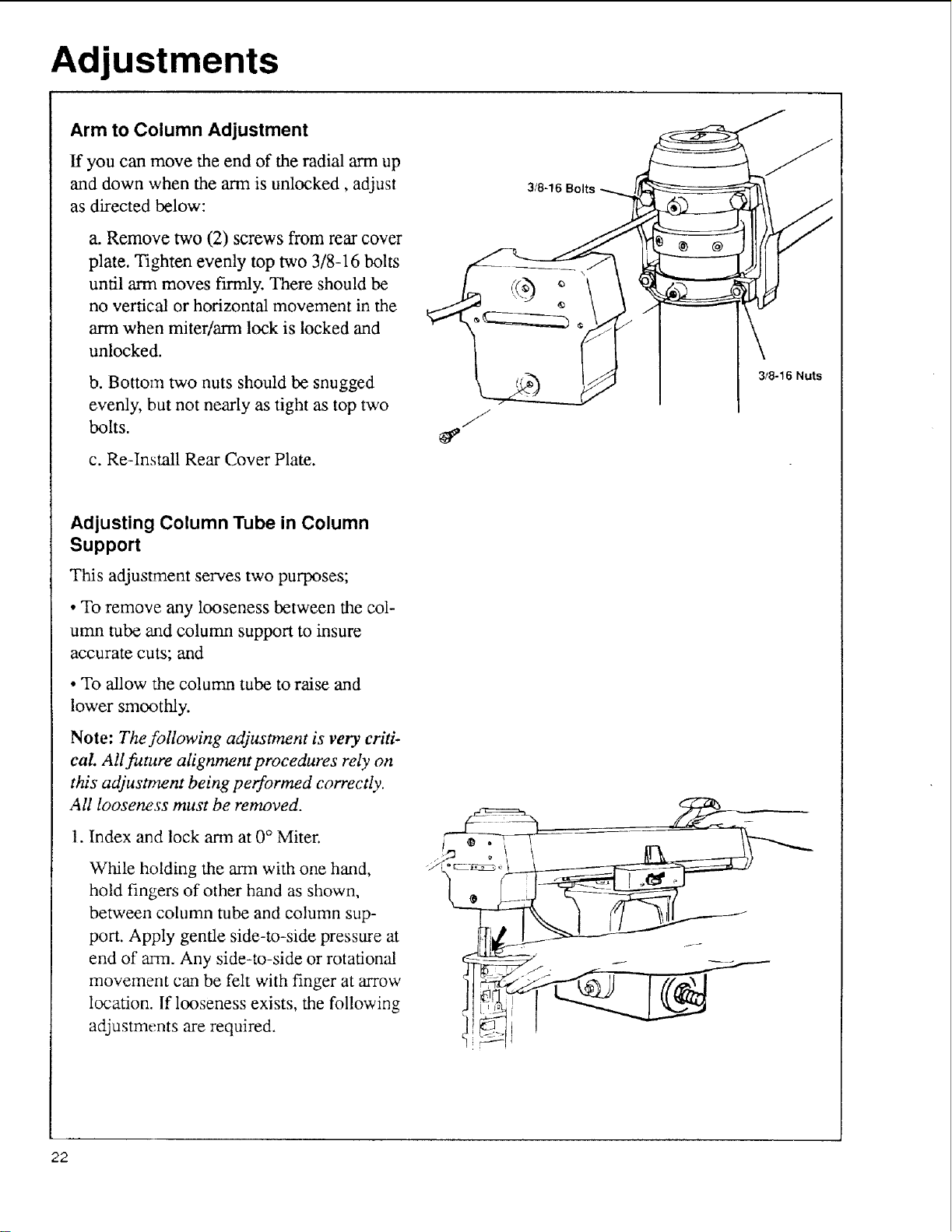
Arm to Column Adjustment
If you can move the end of the radial arm up
and down when the ann is unlocked, adjust
as directed below:
a. Remove two (2) screws from rear cover
plate. Tighten evenly top two 3/8-16 bolts
until arm moves firmly. There should be
no vertical or horizontal movement in the
arm when miter/arm lock is locked and
unlocked.
b. Bottom two nuts should be snugged
evenly, but not nearly as tight as top two
bolts.
c. Re-Install Rear Cover Plate.
3/8-16 Bolts
3/8-16 Nuts
Adjusting Column Tube in Column
Support
This adjustment serves two purposes;
• To remove any looseness between the col-
umn tube and column support to insure
accurate cuts; and
• To allow the column tube to raise and
lower smoothly.
Note: The following adjustment is very criti-
cal All future alignment procedures rely on
this adjustment being performed correctly.
All looseness must be removed.
1. Index and lock arm at 0 ° Miter.
While holding the arm with one hmad,
hold fingers of other hand as shown,
between column tube and column sup-
port. Apply gentle side-to-side pressure at
end of arm. Any side-to-side or rotational
movement can be felt with finger at arrow
location. If looseness exists, the following
adjustments are required.
22
Adjustments
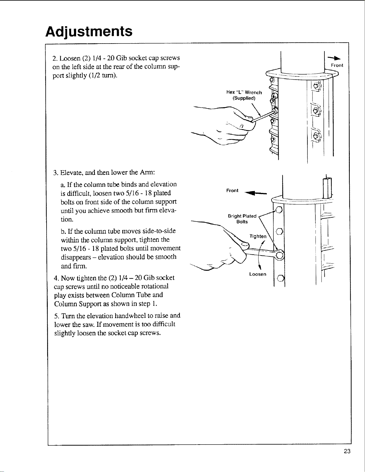
2. lax)sen (2) 1/4 - 20 Gib socket cap screws
on the left side at the rear of the column sup-
port slightly (1/2 turn).
3. Elevate, and then lower the Ann:
a. If the column tube binds and elevation
is difficult, loosen two 5/16 - 18 plated
bolts on front side of the column support
until you achieve smooth but firm eleva-
tion.
b. If the column tube moves side-to-side
within the column support, tighten the
two 5/16 - 18 plated bolts until movement
disappears - elevation should be smooth
and firm.
-
Hex "L" Wrench _ _ "_
(Supplied) 1_ I
Front
J
5
Bright Plated
Bolts
1
Front
/
t
4. Now tighten the (2) 1/4 - 20 Gib socket
cap screws until no noticeable rotational
play exists between Column Tube and
Column Support as shown in step 1.
5. Turn the elevation handwheel to raise and
lower the saw. If movement is too difficult
slightly loosen the socket cap screws.
©
23
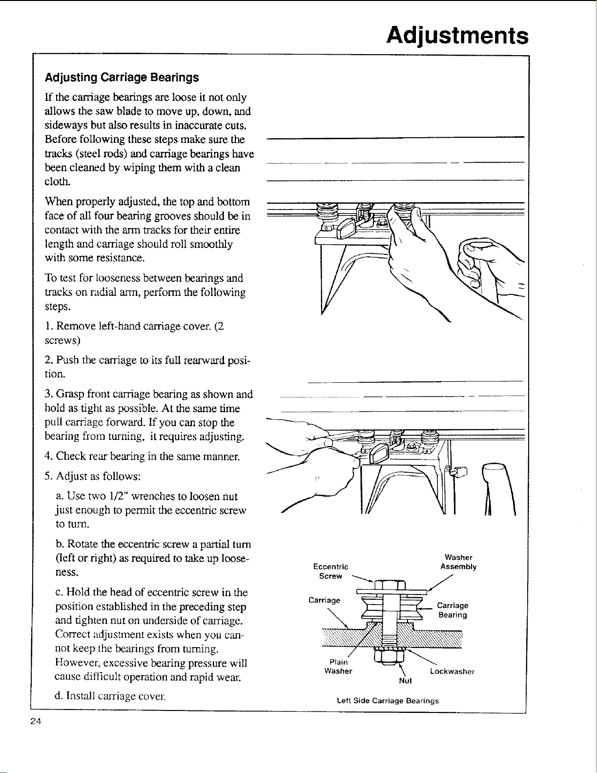
Adjusting Carriage Bearings
ff the carriage bearings are loose it not only
allows the saw blade to move up, down, and
sideways but also results in inaccurate cuts.
Before following these steps make sure the
tracks (steel rods) and carriage bearings have
been cleaned by wiping them with a clean
cloth.
When properly adjusted, the top and bottom
face of all four bearing grooves should be in
contact with the arm tracks for their entire
length and carriage should roll smoothly
with some resistance.
To test for looseness between bearings and
tracks on radial arm, perform the following
steps.
Adjustments
1. Remove left-hand carriage cover. (2
screws)
2. Push the carriage to its full rearward posi-
tion.
3. Grasp front carriage bearing as shown and
hold as tight as possible. At the same time
pull carriage forward. If you can stop the
bearing from turning, it requires adjusting.
4. Check rear bearing in the same manner.
5. Adjust as follows:
a. Use two 1/2" wrenches to loosen nut
just enough to permit the eccentric screw
to turn.
b. Rotate the eccentric screw a partial turn
Oefl or right) as required to take up loose-
ness.
c. Hold the head of eccentric screw in the
position established in the preceding step
and tighten nut on underside of carriage.
Correct adjustment exists when you can-
not keep the bearings from turning.
However, excessive bearing pressure will
cause difficult operation and rapid wear.
Eccentric
Screw
Carriage
Plain
Washer Loekwasher
Nut
Washer
Assembly
Carriage
Bearing
d. Install carriage cove1;
24
Left Side Carriage Bearings
 Loading...