


113.239291
Sears
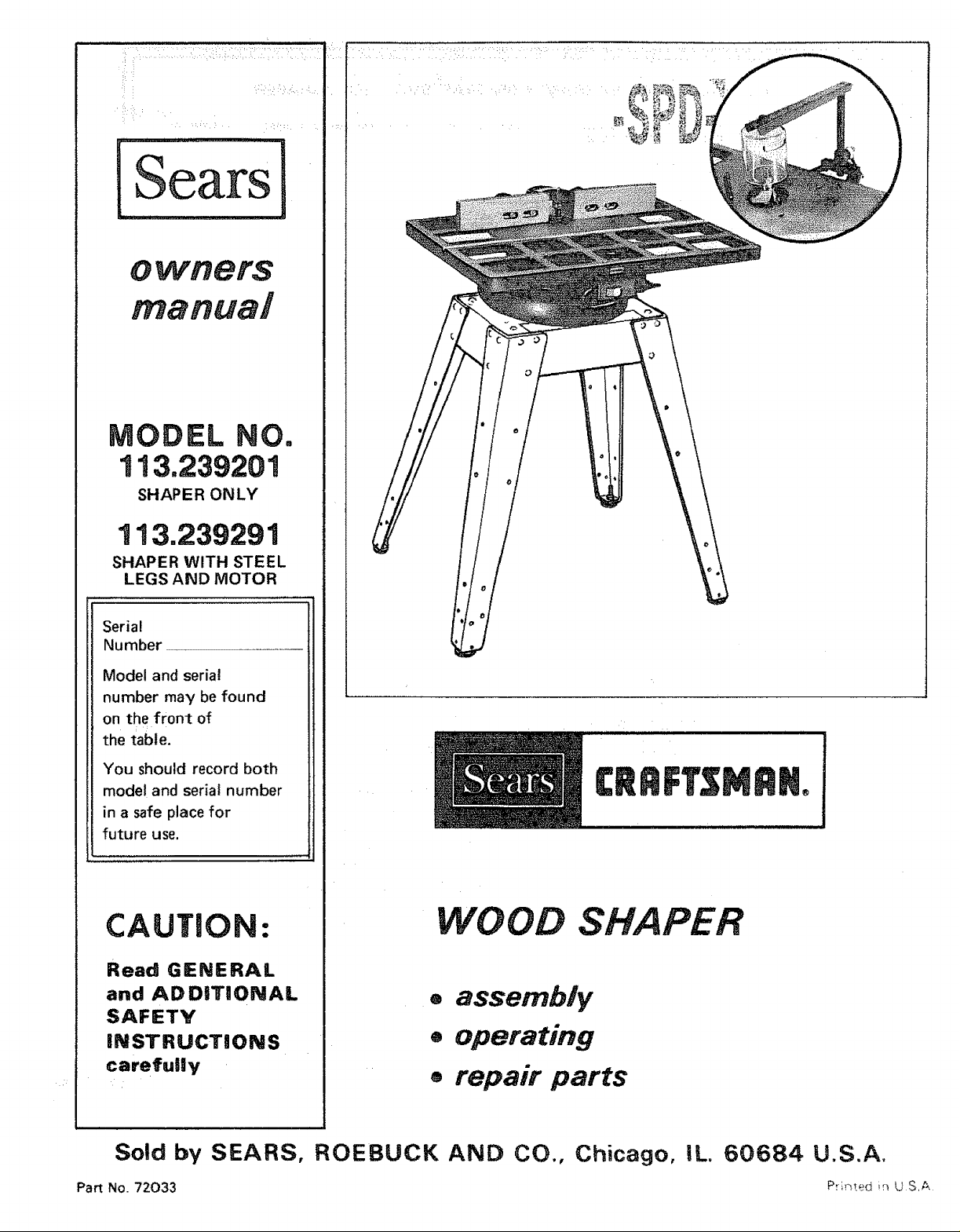
MODEL NO,
113.239201
SHAPER ONLY
113.239291
SHAPER WITH STEEL
LEGS AND MOTOR
Serial
Number
Model and serial
number may be found
on the front of
the table.
You should record both
model and serial number
in a safe place for
future use.
CAUTION:
Read GENERAL
and ADDITIONAL
SAFETY
iNSTRUCTiONS
carefui|y
WOOD SHAPER
o assembly
+ operating
o repair parts
Sold by SEARS, ROEBUCK AND CO., Chicago, IL 60684 U.S.A.
Part No. 72033 Pr',_ed in U S,A
ON CRAFTSMAN WOOD:SHAPER
this Craftsman: Wood Shaper fails duel to a defect in material or
AVAILABLE BY SIMPLY CONTACTING THE NEAREST SEARS STORE OR SERVICE
_her rights which vary from state to state,
Sears Tower. Chicago, IL 60684
general safety
-, :i • : rInstructions fo power tools
1. KNOW YOUR POWER TOOL
Read and understand the owner's manual and labels
affixed to the toot. Learn its application and
limitations as wel! as the specific potential hazards
peculiar to this too!,
2. GROUND ALL TOOLS
This tool is equipped w_th an approved 3-conductor
Cord and a 3-prong grounding type plug to fit the
proper grounding type receptacle. The green conductor
in the cord is the grounding wire. Never connect the
green wire to a live terminal.
3. KEEP GUARDS tN PLACE
in working order, and in proper adjustment and
alignment,
4, REMOVE ADJUSTING KEYS
AND WRENCHES
Form habit of checking to see that keys and adjusting
wrenches are removed from tool before turning it on.
5. KEEP WORK AREA CLEAN
Cluttered areas and benches inwte accidents. Floor
must notbe slippery due to wax or sawdust.
6.:AVOID DANGEROUS ENVIRONMENT
Don't-use power:tools in damp or wet locations or
expose them tO Cain. Keepw0(k' area we lighted.
Provide adequate surrounding work space.
7, KEEP CHtLDREN AWAY
All vis=tors sho_J|d be kept-a safedistance from work
area.
8. MAKE WORKSHOP KID-PROOF
with padlocks, master switches, or by removing
starter keys.
9. DON'T FORCE TOOL
It will do the job better and safer at the rate for which
tt was desMgned
10. USE RIGHT TOOL
Don't force tool or attachmem to do a job _t was not
designed for.
11. WEAR PROPER APPAREL
DO not wear loose clothing, gloves, neckties or jewelry
(rings, wrist watches) to get caught in moving parts.
Nonsfip footwear is recommended. Wear protective
hair covering to contain long hair. Roll long sleeves
above the el bow.
12. USE SAFETY GOGGLES (Head Protection)
Wear Safety goggles (must comply with ANSi Z87.1)
-at all times.: Everyday eyeglasses 0nly have impact
resistant _lenSes,;they: are NOT-safety glasses.,Also, use
face or dust mask if cutting operation is dusty, and ear
protectors (plugs or muffs) during extended periods of
operation,
13. SECURE WORK
Use clamps or a vise to hold work when practical, It's
safer than using your hand, frees both hands to operate
tool
14. DON'T OVERREACH
Keep proper footing and balance at all times.
15.
MAINTAIN TOOLS WITH CARE
Keep tools sharp and clean for best and safest
performance. Follow instructions for lubricating and
changing accessories.
16. DISCONNECT TOOLS
before servicing; when changing accessories such as
blades, bits, cutters, etc.
17. AVOID ACCIDENTAL STARTING
Make sure switch is in "OFF" position before plugging
in,
18. USE RECOMMENDED ACCESSORIES
Consult the owner's manual for recommended
_accessories, Follow the instructions that accompany
i::,!!:i:i;_:!:,i:::!::tfi_:'accessories. The use of improper accessories mav
hazards,
STAND ON TOOL
.... Serious injury could occur if the tool is tipped or if the
: cutting tool is accidentally contacted.
Do not store materials above or near the toot such that
it _snecessary to stand on the tool to reach them.
20. CHECK DAMAGED PARTS
Before further use of the tool, a guard or other part that
is damaged should be carefully checked to ensure that it
will operate properly and perform _ts intended function.
Check for alignment of moving parts, binding of mowng
parts, breakage of parts, mounting, and any other
conditions that may .affect its operation. A guard or
other part that is damaged should be properly repaired
or replaced.
21. DIRECTION OF FEED
Feed work into a blade or cutter against the direction
of rotation of the blade or cutter only,
22. NEVER LEAVE TOOL RUNNING
UNATTENDED
Turn power off. Don't leave tool until it comes to a
complete stop.

:ilADDITIONAL SAFETY INSTRUCTIONS
FOR WOOD SHAPER
CAUTION: Turn motor switch "OFF" and disconnect 18, DO NOT perform layout, assembly, or set-Up work on
Power Cord when changing Shaper cutters or making
adjustments.
Safety is a combination of operator common sense and
alertness at all times when the Wood Shaper is being used,
WARNING: FOR YOUR OWN SAFETY, DO NOT
ATTEMPT TO OPERATE YOUR WOOD SHAPER UNTIL
IT IS COMPLETLY ASSEMBLED AND INSTALLED
ACCORDING TO THE INSTRUCTIONS.,. AND UNTIL
YOU HAVE READ AND UNDERSTAND THE
FOLLOWING:
PAGE
1. General Safety Instructions for Power Tools ..... 2
2, Getting to Know your Wood Shaper ............ 11
3. Basic Wood Shaper Operation ................. t4
4. Maintenance .............................. t8
5. Stability of Machine
The Shaper must be bolted securely to a stand or work
bench, in addition, if there is any tendency for the
Shaper to tip over or move during certain operations, it
should be bolted to the floor.
6, Location
The Shaper should be positioned so neither the
operator nor a casual observer is forced to stand in line
with the workpiece when straight line shaping. This
Shaper is intended for indoor use only.
7. Protection: Eyes, Hands, Face, Ears, Body
Wear safety goggles that comply with ANSI Z87.1
1968. Wear ear plugs or muffs during extended periods
of operation, Do not wear gloves .., roll long sleeves
above the elbow,
8, Always feed against rotation of the cutter. NEVER
"back up" the workpiece.
9. Do not take deep cuts or feed the stock too rapidly.
10. Be particularly careful in shaping wood that contains
cross grains or knots, as these may cause the hands to
be thrown into the cutter or cause kickbacks.
11. Before applying power, make sure the keyed washer is
installed immediately under the spindle nut and the
spindle nut is securely fastened, and all guards are in the
proper position, Make sure cutters are sharp,
12. Avoid awkward hand positions, where a sudden slip
could cause a hand to move into the cutt:er. Never reach
in back of or around the cutter with either hand to hold
down the workpiece.
13. Accumulations of stock or of finished work should not
be allowed on the table. Never clear table while cutter is
rotating.
14. Rubbish, shavings, stock, or other objects or material
should not be allowed on the floor where they may be a
tripping hazard.
15. Use working forms, patterns or holders wherever
possible, and keep them maintained, Care should be
taken that the work is securely fastened in these
fixtures, Stock is often of such size or shape that it
must be clamped in a holder before being shaped, The
inside jaws which clamp directly against the stock
should be lined with sand paper, Guards may also be
:mounted on a holder to afford additional protection.
16: When the fence is used, make sure it Ts securely fastened
and will not slip, and is properly adjusted.
17, Do not wear gloves, neckties, loose sleeves, or ragged or
torn clothing of any kind. Wear safety goggles
complying with ANSI Z87,1-t968 to protect your eyes
from dust or flying particles.
the table while the cutting tool is rotating.
19. NEVER perform freehand shaping - Use either the
fence, or a starting pin in the table and a collar on the
spindle, or a pattern.
20. Do not place your fingers or hands near edge of
material being cut.
21. NEVER perform irregular shaping operations with the
cutter guard removed. Be positive it is installed and
adjusted per instructions.
22. NEVER perform internal shaping operations on this
Shaper.
23. Do not use your hands to remove objects or materials
from around cutters; use a brush.
24. Do not tamper with guards nor make them inoperative
in any way.
25. ALWAYS joint or plane edge on surface of workpiece
that will be in contact with fence and/or table.
26. NEVER attempt to shape warped or twisted or bowed
work pieces.
27. Before leaving the machine, make sure the motor switch
is "OFF" the power cord is disconnected from the
power source, and the cutter has stopped revolving.
28. Never operate the Shaper without a protective cover on
the ur_used shaft end of a double ended motor.
29. If any part of this Shaper should break, bend, or fail in
any way or any electrical component fail to perform
properly, or if any is missing, shut off power switch,
remove power supply cord from power supply and
replace damaged missing and/or failed parts before
resuming operation.
WARNING: DO NOT ALLOW FAMILIARITY (GAINED
FROM FREQUENT USE OF YOUR WOOD SHAPER)TO
BECOME COMMONPLACE, ALWAYS REMEMBER
THAT A CARELESS FRACTION OF A SECOND IS
SUFFICIENT TO INFLICT SEVERE INJURY.
30. Note and follow Safety Instructions that appears on the
Shape:r fence.
WAR NIN G
A KEYED WASHER MUST ALWAYS
BE USED UNDER THE SPINDLE NUT
31. Note and follow Safety Instructions that appear on the
Shaper Switch assembly.
DANGER
FOR YOUR OWN SAFETY:
_EAO AND UNDERSTANO OWN£R S
MANUAL BEFORE OPERATING MACH_N£
1 W£AR S_FET¥ GOGGLES PStq AN$!2'87 t
AT ALL TIME&t
2 BE POStTIVE KEYED _,_,q-_,_._ _S DER_CTLY
LINDE_ gPIN_LE NU? A_ SPJNDL£" NLET IS
TtGHT _E_OR_. T'ORNtN{_ S_4*_.P_R "ON
3 ALWAYS cEED WO_KPIEC£ AGA!N_T
ROTATION OF CUTTER MOTOR AND
CUTTER _OTATE tN SAME QIRECTIO_
4 AVOId" AWK_A_ F,[_._ _OSJ'TIONS
5 _EEP F_NGE_S AWAY _ROM REVOLVING
C{JTTER _ US_ FI×TURE_ WHEN
N_CESSA_tY
6 tJSE OVERHEAD GUARD WH_4 ADJUS1-
ABL_. F_NC£ _S NOT JN PLACE
WARNING: THE 4-3/8" FLAT PULLEY AND THE 2"
MOTOR PULLEY FURNISHED, WILL RUN THE
CUTTER APPROXIMATELY 9000 R,P,M. WHEN
USED WITH A 3450 MOTOR, NEVER SUBSTITUTE
THESE PULLEYS TO INCREASE THIS SPEED
BECAUSE IT COULD BE DANGEROUS.
resultin foreign
objectsbeingthrownintothe,eyes;whichcanresultin
ilseve:re:eyedamageiAlWayswearsafetyg0gglescomplying
;i:_i;_hANSI:Z87_1(shoWnOnPackage)beforecommencing
powe_tooloperation.SafetyGogglesare available at Sears
retaiFbr catalog stores.
MOTOR SPECUFRCATIONS AND
ELECTRICAL REQUIREMENTS
TtiiS rnachine is designed to use a 3450 R.P.M. Motor only.
DOnot use any motor that runs faster than 3450 R.P.M. It
is: wired for _peration on 115 volts, 60 Hz., alternating
current; IT MUST NOT BE CONVERTED TO OPERATE
ON 230 VOLTS, EVEN THOUGH SOME OF THE
RECOMMENDED MOTORS ARE DUAL VOLTAGE.
THESE CRAFTSMAN MOTORS HAVE BEEN FOUND TO
BE ACCEPTABLE FOR USE ON THIS TOOL.
HP RPM VOLTS CATALOG NO.
1/2 3450 115 12!6
1/2 3450 115 1218
_:3/4 3450 115 1219
115 1226
1/2, _ 3450 115 1269"
"MOtor has reversing switch
CAUTION: Do notuse blower or washing machi ne motors
or any motor with an automatic reset overload protector as
their use may be hazardous.
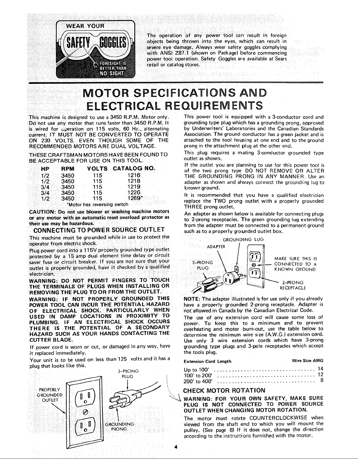
CONNECTING TO POWER SOURCE OUTLET
This machine must be grounded While in use to protect the
This power tool is equipped with a 3-conductor cord and
grounding type plug which has a grounding prong, approved
by Underwriters' Laboratories and the Canadian Standards
Association. The ground conductor has a green jacket and is
attached to the toot housing at one end and to the ground
prong in the attachment plug at the other end.
This plug requires a mating 3-conductor grounded type
outlet as shown.
If the outlet you are planning to use for this power tool is
of the two prong type DO NOT REMOVE OR ALTER
THE GROUNDING PRONG IN ANY MANNER. Use an
adapter as shown and always connect the grounding lug to
known ground,
It is recommended that you have a qualified electrician
replace the TWO prong outlet with a properly grounded
THREE prong outlet,
An adapter as shown below is available for connecting plugs
to 2-prong receptacles. The green grounding lug extending
from the adapter must be connected to a permanent ground
such as to a properly grounded outlet box.
GROUNb|NG LUG
Plug power _ord idto a i 15v properly :grounded type outlet ADAPTER .........
sa;_er fUse:o[: ch:cuit breaker. If you:are not: sure that _0Qr S-PRoNG \_ _ t CONNECTED TO A
WARNING: DO NOT PERMIT FINGERS TO TOUCH 2-PRONG
THE TERMINALS OF PLUGS WHEN INSTALLING OR RECEPTACLE
REMOVING THE PLUG TO OR FROM THE OUTLET.
WARNING:: IF NOT PROPERLY GROUNDED THIS
POWER TOOL CAN INCUR THE POTENTIAL HAZARD
OF ELECTRICAL SHOCK. PARTICULARLY WHEN
USED IN DAMP LOCATIONS IN PROXIMITY TO
PLUMBING. IF AN ELECTRICAL SHOCK OCCURS
THERE iS THE POTENTIAL OF A SECONDARY
HAZARD SUCH AS YOUR HANDS CONTACTING THE
CUTTER BLADE.
If power cord is worn or cut, or damaged in any way, have
it replaced immediately.
Your unit is to be used on less than 125 volts and it has a
plttg that looks like this.
3-PRONG
PLUG ,
PROPERLY___ _ _:
RouND oII-Fn Ui
i OUT GROUNDING
_ PRONG
i
NOTE: The adapter illustrated is for useonly if you already
have a properly grounded 2-prong receptacle. Adapter is
not allowed in Canada by the Canadian Electrica! Code,
The use of any extension cord will cause some loss of
power, To keep this to a minimum and to prevent
overheating and motor burn-out, use the table below to
determine the minimum wire stze (A.W.G.) extension cord.
Use only 3 wire extension cords which have 3-prong
grounding type plugs and 3-pote receptacles which accept
the tools plug.
Extension Cord Length
Wire Size AWG
Up to100' . ................................. 14
100' to 200' . .................................. 12
200' to 400' . ................................ 8
CHECK MOTOR ROTATION
WARNING: FOR YOUR OWN SAFETY, MAKE SURE
PLUG IS NOT CONNECTED TO POWER SOURCE
OUTLET WHEN CHANGING MOTOR ROTATION.
The motor must rotate COUNTERCLOCKWISE when
viewed from the shaft end to which you will mount the
pulley. (See page 8) If it does not, change the direction
according to the instructions furnished with the motor.
UNPACKmNG: AND
CONTENTS
WARRANTY ................................
General Safety Instruction for Power Tools .........
Additional Safety Instructions for Wood Shaper .....
Motor Specifications and Electrical Requirements ....
UNPACKING AND CHECKING CONTENTS .......
List of Loose Parts ..........................
ASSEMBLY .................................
Tools Needed ..............................
Installing Elevating Rod and Table Support .......
Mounting Belt Guard and Motor to Motor Mount +.
Checking Motor Rotation .....................
Installing Motor Pulley .......................
Mounting Motor Support Assembly to Shaper .....
Mounting Switch Assembly ...................
CHECKING CONTENTS
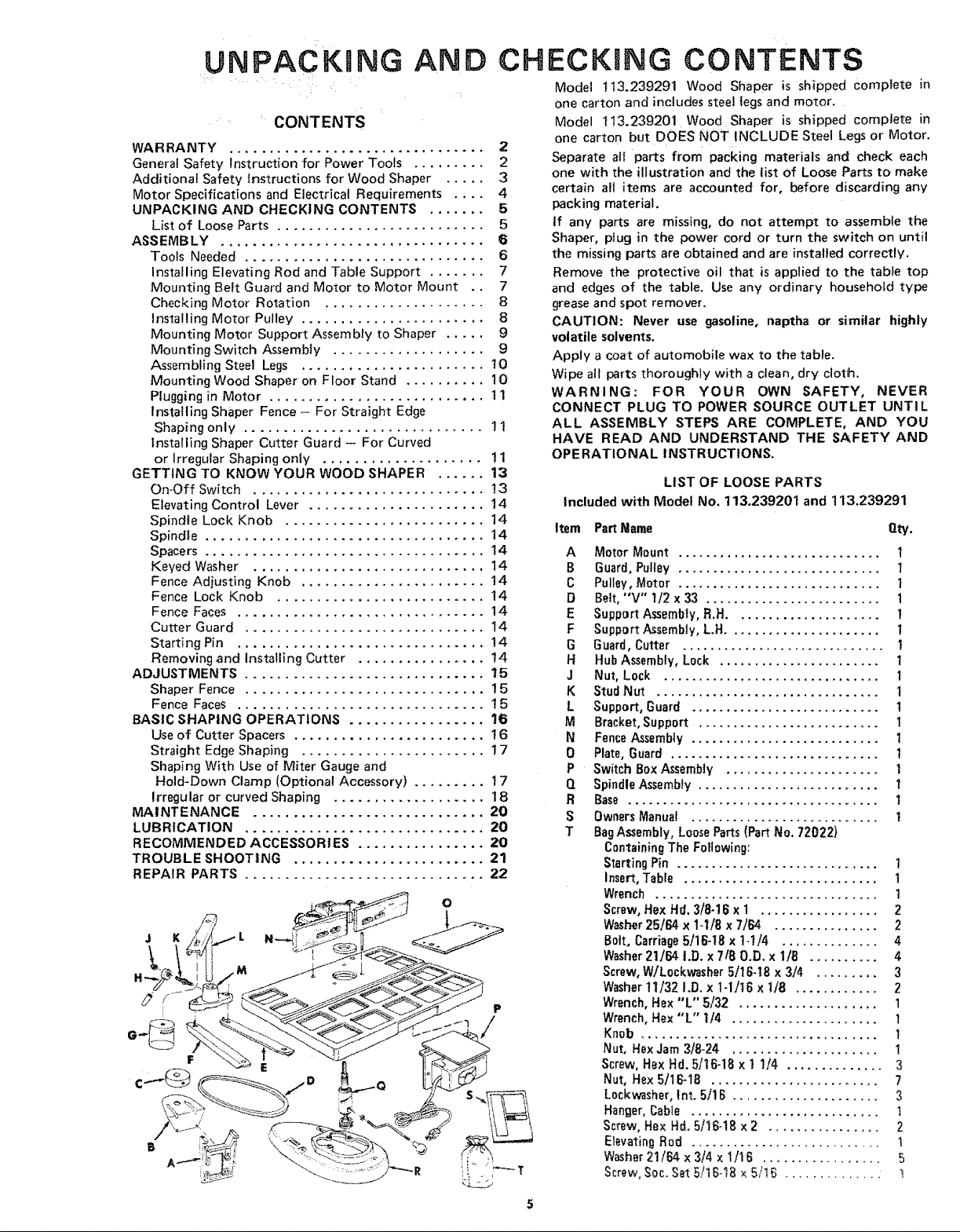
Model 113.239291 Wood ShaPer is shipped Complete in
one carton and includes steel legs and motor.
Model 113.239201 Wood Shaper is shipped complete in
one carton but DOES NOT INCLUDE Steel Legs or Motor.
2
2 Separate all parts from packing materials and check each
3 one with the illustration and the list of Loose Parts to make
4 certain all items are accounted for, before discarding any
5 packing material.
5 tf any parts are missing, do not attempt to assemble the
6 Shaper, plug in the power cord or turn the switch on until
6 the missing parts are obtained and are installed correctly.
7 Remove the protective oil that is applied to the table top
7 and edges of the table. Use any ordinary household type
8 grease and spot remover.
8 CAUTION: Never use gasoline, naptha or similar highly
9 volatile solvents.
9 Apply a coat of automobile wax to the table.
Wipe all parts thoroughly with a clean, dry cloth.
WARNING: FOR YOUR OWN SAFETY, NEVER
CONNECT PLUG TO POWER SOURCE OUTLET UNTIL
ALL ASSEMBLY STEPS ARE COMPLETE, AND YOU
HAVE READ AND UNDERSTAND THE SAFETY AND
OPERATIONAL INSTRUCTIONS.
Assembling Steel Legs ....................... 10
Mounting Wood Shaper on Floor Stand ............ 10
Plugging in Motor ........................... 1 1
Installing Shaper Fence + For Straight Edge
Shaping only .............................. 1 t
Installing Shaper Cutter Guard - For Curved
or Irregular Shaping only .................... 11
GETTING TO KNOW YOUR WOOD SHAPER ...... 13
On-Off Switch ............................. !3
Elevating Control Lever ...................... 14
Spindle Lock Knob ......................... 14
Spindle ................................... 14
Spacers .................................... 14
Keyed Washer ............................. 14
Fence Adjusting Knob ....................... 14
Fence Lock Knob .......................... 14
Fence Faces ............................... 14
Cutter Guard .............................. 14
Starting Pin ............................... 14
Removing and Installing Cutter ................ 14
ADJUSTMENTS .............................. 15
Shaper Fence .............................. 1 5
Fence Faces ............................... 1 5
BASIC SHAPING OPERATIONS ................. 16
Use of Cutter Spacers ........................ t 6
Straight Edge Shaping ....................... 1 7
Shaping With Use of Miter Gauge and
Hold+Down Clamp (Optional Accessory) ......... 1 7
Irregular or curved Shaping ................... 18
MAINTENANCE ............................. 20
LUBRICATION .............................. 20
RECOMMENDED ACCESSORIES ................
TROUBLE SHOOTING ........................ 21
REPAIR PARTS .............................. 22
LIST OF LOOSE PARTS
Included with Model No, 113.239201 and 113.239291
Item PartName Qty.
A
B
C
D
E
F
G
H
J
K
L
M
N
0
P
Q
R
S
T
Motor Mount ............................. I
Guard, Pulley ............................. 1
Pulley, Motor ............................. 1
Belt, "'V'" 1/2 x 33 ......................... 1
Support Assembly, R.H ..................... !
Support Assembly,LH ...................... I
Guard,Cutter ............................. +
Hub Assembly,Lock ....................... I
Nut,Lock ............................... I
StudNut ................................ I
Support, Guard ........................... 1
Bracket, Support .......................... 1
Fence Assembly ........................... 1
Plate, Guard .............................. 1
Switch Box Assembly ...................... I
Spindle Assembly .......................... 1
Base .................................... 1
Owners Manua{ ........................... 1
Bag Assembly, Loose Parts (Part No. 72022)
Containing The Following:
Starting Pin ............................. 1
Insert, Table ............................ 1
Wrench ................................ 1
Screw, Hex Hd. 3/8-1B x 1 ................. 2
Washer25164x 1-118x 7164 ............... 2
B01t+ Carriage 5/16-18 x 1-114 .............. 4
Washer 21]64 I.D. x 7 tB 0.D. x lib .......... 4
Screw, W/L0ckwasher 5]16-t8 x 3/4 ......... 3
Washer11/321.D. x1+1116 x1/8 ............ 2
Wrench, Hex "L" 5]32 .................... 1
Wrench, Hex "L" I/4 ..................... 1
Knob .................................. 1
Nut, Hex Jam 3/8-24 ..................... !
Screw, Hex Hd+ 5/16-18 x 1 1/_, .............. 3
Nut, Hex 5/16-18 ........................ 7
L0ckwasher, Int. 5]! B ..................... 3
Hanger,Cable ........................... 1
Screw, He× Hd. 5/_6-18 x 2 ................ 2
Elevating Rod ........................... 1
Washer 21/84 x 3/4 x 1/16 ................. 5
Screw, Soc. Set 5/1E;..l_ x 5/1_ 1
i ii:izzi ¸/:! ! iii ¸¸:,
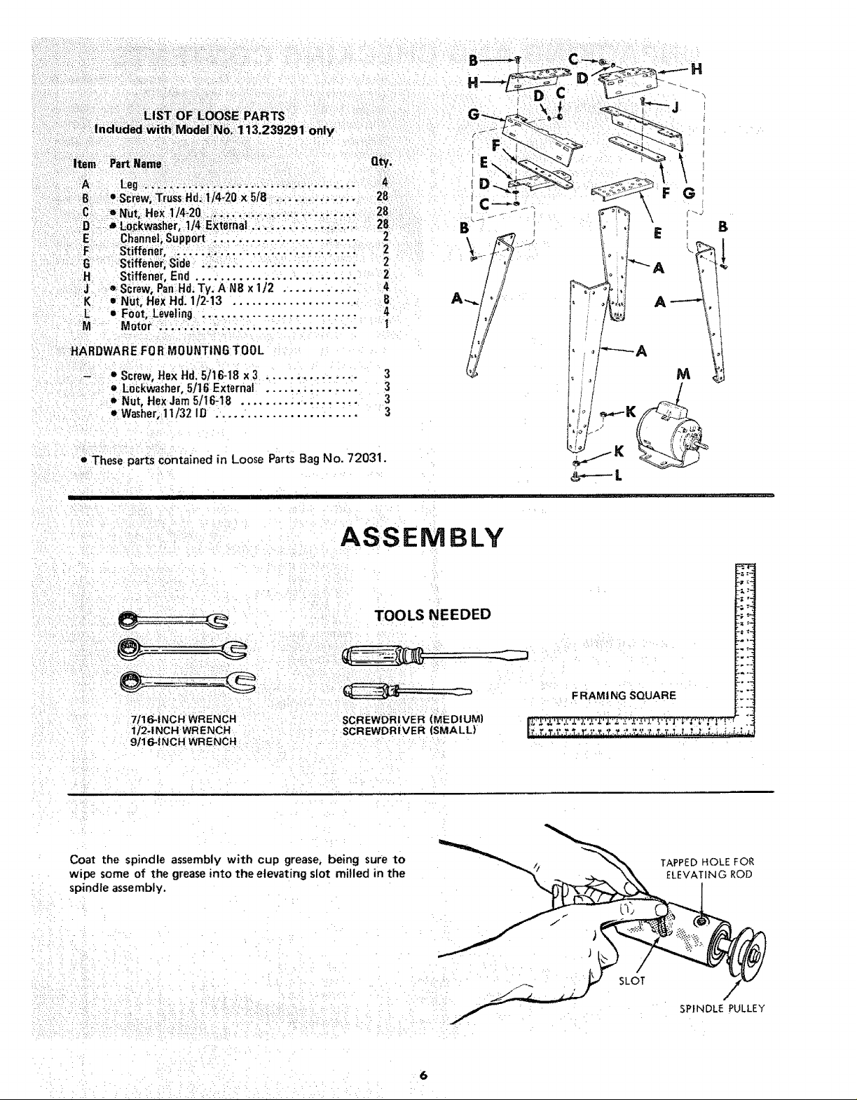
Induded With ModeiNo;: 113.239291 only
¢
nty.
8 _=.Screw,Truss:Hd_Ii4o20x 5/B: ,,,:.............. 28
c:i:D_"Nut,_RexIJ4_2o...:;.........................2B
....i:Loci(washer; 1/4:External. _.;. :.:,. .... _=.,;L,. 28
......E Cl_anneliSuppb_ti.,. .......... .. ,. _,.., 2
F
Stiffener, i....!_.;...,,,,... .... :.i...; 2
..... G ::-Stiffener; Side ......................... 2
.H Stiffener, End .......................... 2
e;Screw,Pan Hd.Ty, A N8 x 1/2 ............ 4
Nut, HeXHd. 1/2-13 .................... B
L • Foot, Leveling .......................... 4
M Motor ......... ; ...................... 1
:HARDWAREFOR MOUNTING TOOL
_ • Screw,Hex Hd,5/16-18 x 3 3
• Lockwasher,5/lBExterna _!_:.ii_i_i_ 3
oNut, Hex Jarn5/16-18 ................... 3
• Washer,11/32 ID ....................... 3
• These parts contained in Loose Parts Bag No. 72031.
' III
C
B
A
_----L
ASSEMBLY
i
7/16-INCH WRENCH
1I2-1NCH WR ENCH ......
9/16-_ NCH WRENCH
TOOLS NEEDED
SCREWDRIVER (MEDIUM}
SCREWDRIVER (SMALL)
F RAMI NG SQUARE
Coat the spindle assembly with cup grease, being sure to
wipe some of the greaseinto the elevating slot milled in the
spindle assembly.
SLOT
TAPPED HOLE FOR
ELEVATING ROD
SPINDLE PULLEY
6
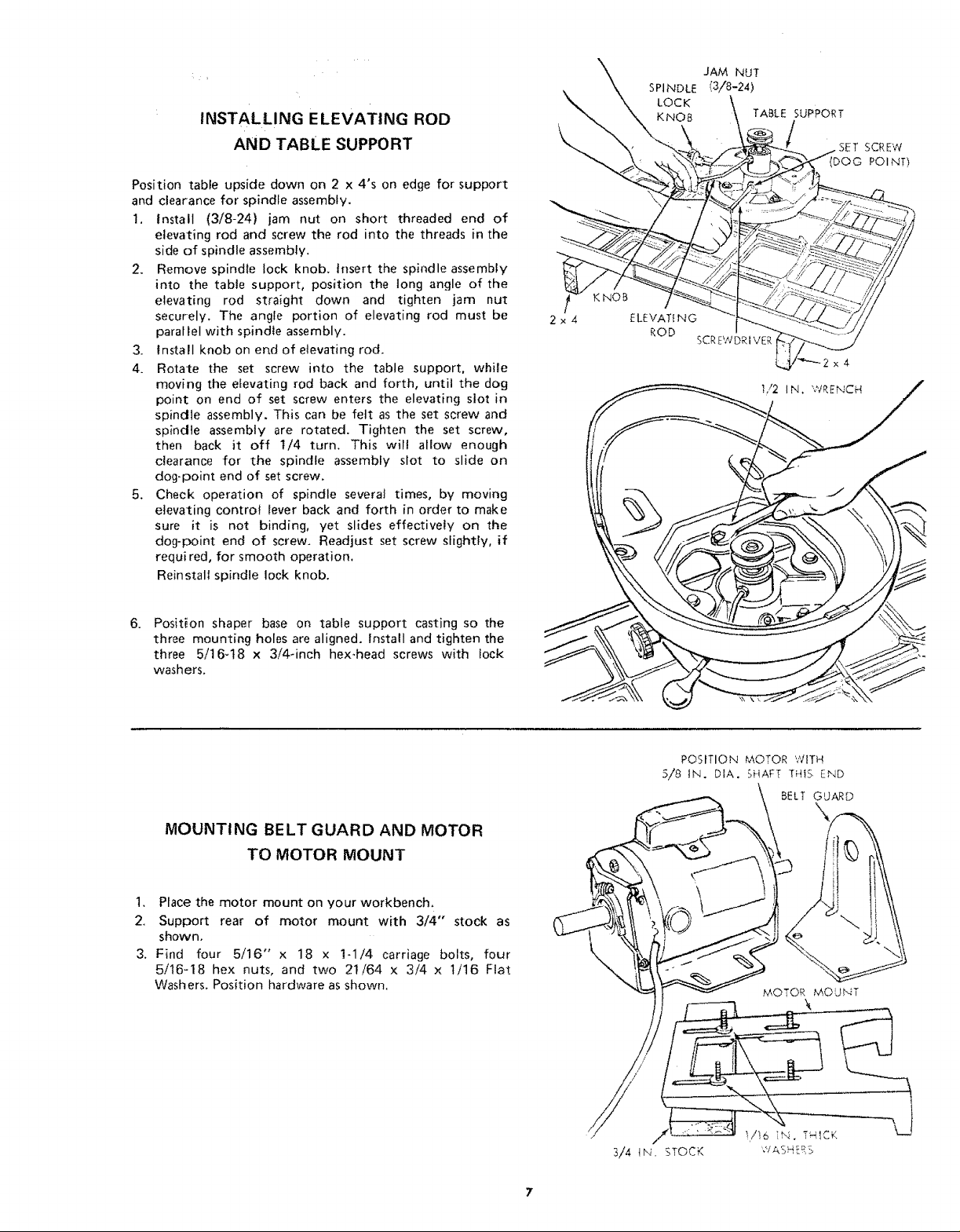
INSTALLING ELEVATING ROD
AND TABLE SUPPORT
Position table upside down on 2 x 4's on edge for support
and clearance for spindle assembly.
1. Install (3/8-24) jam nut on short threaded end of
elevating rod and screw the rod into the threads in the
side of spindle assembly.
2. Remove spindle lock knob. htsert the spindle assembly
into the table support, position the tong angle of the
elevating rod straight down and tighten jam nut
securely. The angle portion of elevating rod must be
parallel with spindle assembly.
3. Install knob on end of elevating rod.
4. Rotate the set screw into the table support, while
moving the elevating rod back and forth, until the dog
point on end of set screw enters the elevating slot in
spindle assembly. This can be felt as the set screw and
spindle assembly are rotated. Tighten the set screw,
then back it off 1/4 turn. This wilt allow enough
clearance for the spindle assembly slot to slide on
dog-point end of set screw,
5. Check operation of spindle several times, by moving
elevating control lever back and forth in order to make
sure it is not binding, yet slides effectively on the
dog-point end of screw. Readjust set screw slightly, if
requi red, for smooth operation.
Reinstall spindle lock knob.
6.
Position shaper base on table support casting so the
three mounting holes are aligned. Install and tighten the
three 5/16-18 x 3i4dnch hex-head screws with fock
washers.
MOUNTING BELT GUARD AND MOTOR
TO MOTOR MOUNT
1. Place the motor mount on your workbench.
2. Support rear of motor mount with 3/4" stock as
shown.
3. Find four 5/16" x 18 x 1-1/4 carriage bolts, four
5/16-18 hex nuts, and two 2t/64 x 3/4 x 1/16 Flat
Washers. Position hardware as shown.
POSITION MOTOR WITH
.5/8 IN. DIA, SHAFT THiS END
BELT GUARD
MOTOR MOUNT
3/4 IN. STOCK
{ u ::
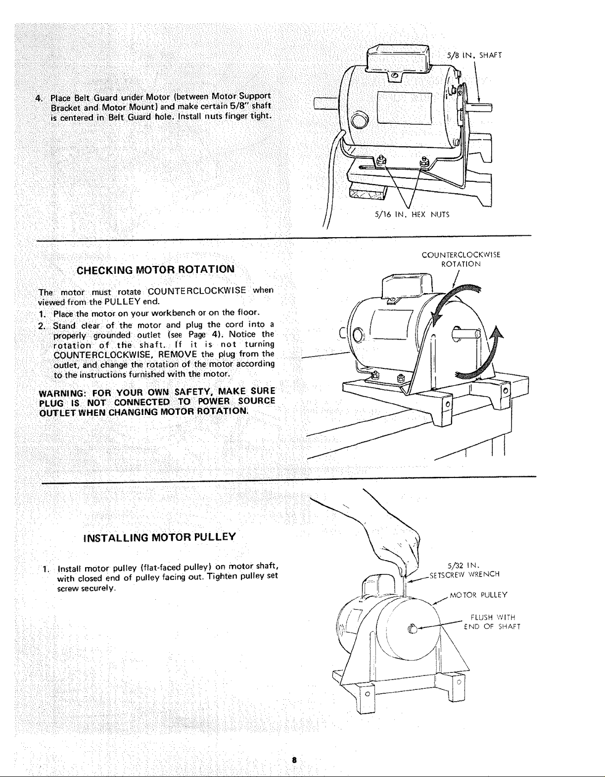
:::4.;!:::Place:':Belti::G_ard iunde_iMotor (between; Motor Support
' i:iB_a_ket and M0torll Mount )and makd certaln 518' shaft
: :is Centeied in •Bblt Guard hoie. :inStall nuts finger tight,
?i!!
5/8 IN. SHAFT
i1t,
5/t6 IN. HEX NUTS
CHECKING MOTOR ROTATION
The motor must rotate COUNTERCLOCKWISE when
viewed from the PULLEY end.
1. Place the motor on your workbench or on the floor.
2. Stand clear of the motor and plug the cord into a
properly,grounded outlet (see Page 4). Notice the
rotation of the shaft, If it is not turning
COUNTERCLOCKWISE, REMOVE the plug from the
Outlet and change the:irotation of the motor according
tO the instructions furnished with the: motor,
WARNING_ FOR YOUR OWN SAFETY, MAKE SURE
PLUG IS NOT CONNECTEDi:TO POWER SOURCE
OUTLET WHEN CHANGING MOTOR ROTATION.
COU NTERCLOCKW]SE
ROTATION
1.
INSTALLING MOTOR PULLEY
\
Install motor pulley (flat-faced pulley) on motor shah,
with closed end of pulley facing out. Tighten pulley set
screw securely.
5/32 lN.
TSCREWWRENCH
MOTOR PULLEY
\
FLUSH WITH
END OF SHAFT
k• ••/, : • .
.
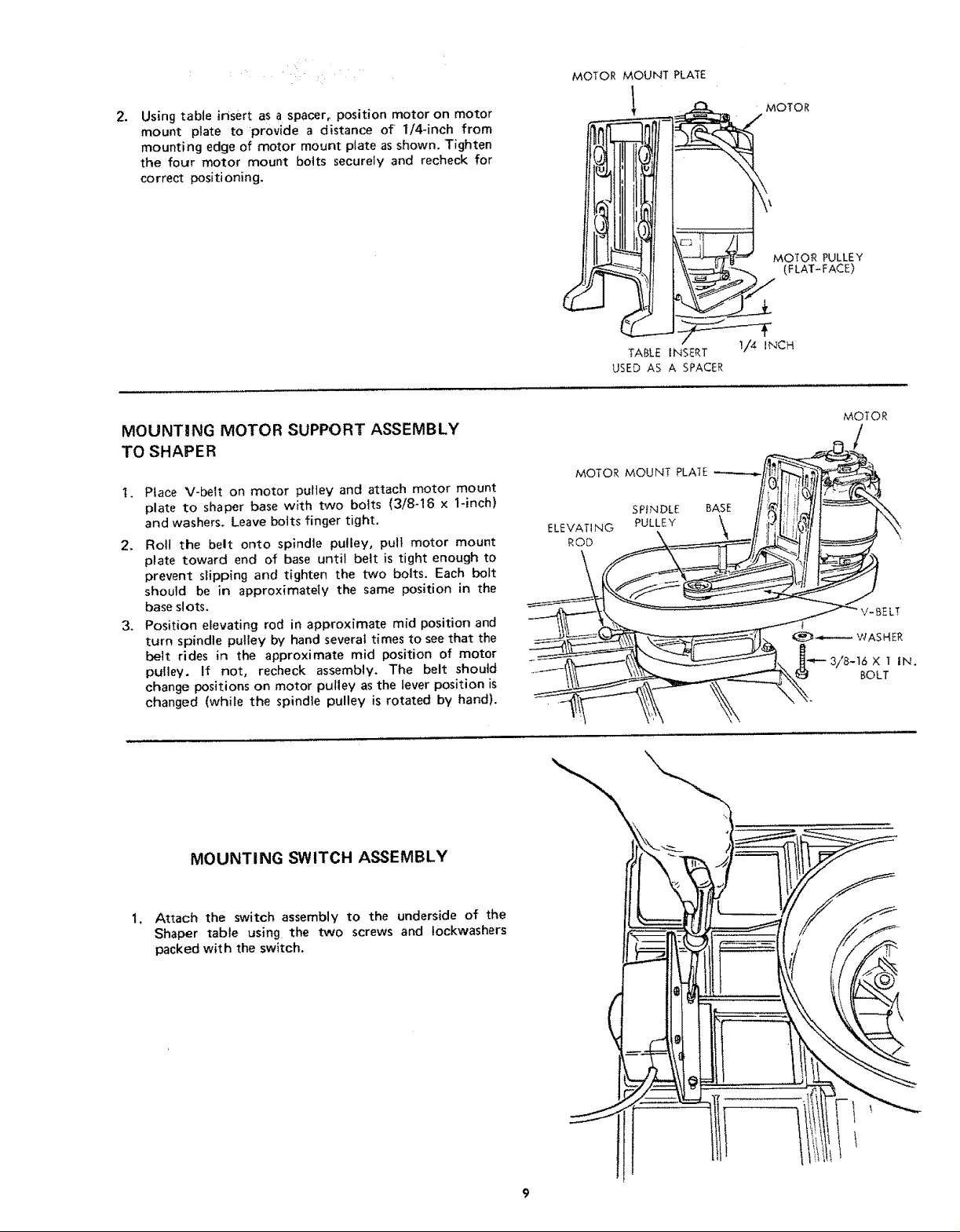
Using table insert as a spacer, position motor on motor
mount plate to provide a distance of 1/4-inch from
mounting edge of motor mount plate as shown. Tighten
the four motor mount bolts securely and recheck for
correct positioning.
MOTOR MOUNT PLATE
MOTOR
MOTOR PULLEY
(FLAT-FACE)
TABLE iNSERT I/4 INCH
USED AS A SPACER
MOUNTING MOTOR SUPPORT ASSEMBLY
TO SHAPER
t. PLace V-belt on motor pulley and attach motor mount
plate to shaper base with two bolts (3/8-16 x 1-inch)
and washers. Leave bolts finger tight.
2. Roll the belt onto spindle pulley, pull motor mount
plate toward end of base until belt is tight enough to
prevent slipping and tighten the two bolts. Each bolt
should be in approximately the same position in the
base slots.
3. Position elevating rod in approximate mid position and
turn spindle pulley by hand several times to see that the
belt rides in the approximate mid position of motor
pulley. If not, recheck assembly. The belt should
change positions on motor pulley as the lever position is
changed (while the spindte pulley is rotated by hand).
MOTOR MOUNT PLATE
SPINDLE
ELEVATING PULLEY
ROD
BASE
MOTOR
"J,
MOUNTING SWITCH ASSEMBLY
Attach the switch assembly to the underside of the
Shaper table using the two screws and lockwashers
packed with the switch.
 Loading...