

Page 1
LINE THERMAL PRINTER
MODEL CT-S601
User’s Manual
Mode d’emploi
Benutzerhandbuch
Manuale dell’utente
Manual de Usuario
Page 2

WEEE MARK
If you want to dispose of this product, do not mix it with general household waste. There is a
En
separate collection systems for used electronics products in accordance with legislation under
the WEEE Directive (Directive 2002/96/EC) and is effective only within European Union.
Wenn Sie dieses Produkt entsorgen wollen, dann tun Sie dies bitte nicht zusammen mit dem
Ge
Haushaltsmüll. Es gibt im Rahmen der WEEE-Direktive innerhalb der Europäischen Union
(Direktive 2002/96/EC) gesetzliche Bestimmungen für separate Sammelsysteme für gebrauchte
elektronische Geräte und Produkte.
Si vous souhaitez vous débarrasser de cet appareil, ne le mettez pas à la poubelle avec vos
Fr
ordures ménagères. Il existe un système de récupération distinct pour les vieux appareils
électroniques conformément à la législation WEEE sur le recyclage des déchets des
équipements électriques et électroniques (Directive 2002/96/EC) qui est uniquement valable
dans les pays de l’Union européenne.
Les appareils et les machines électriques et électroniques contiennent souvent des matières
dangereuses pour l’homme et l’environnement si vous les utilisez et vous vous en débarrassez
de façon inappropriée.
Si desea deshacerse de este producto, no lo mezcle con residuos domésticos de carácter
Sp
general. Existe un sistema de recogida selectiva de aparatos electrónicos usados, según
establece la legislación prevista por la Directiva 2002/96/CE sobre residuos de aparatos
eléctricos y electrónicos (RAEE), vigente únicamente en la Unión Europea.
Se desiderate gettare via questo prodotto, non mescolatelo ai rifiuti generici di casa. Esiste
It
un sistema di raccolta separato per i prodotti elettronici usati in conformità alla legislazione
RAEE (Direttiva 2002/96/CE), valida solo all’interno dell’Unione Europea.
Deponeer dit product niet bij het gewone huishoudelijk afval wanneer u het wilt verwijderen. Er
Du
bestaat ingevolge de WEEE-richtlijn (Richtlijn 2002/96/EG) een speciaal wettelijk
voorgeschreven verzamelsysteem voor gebruikte elektronische producten, welk alleen geldt
binnen de Europese Unie.
Hvis du vil skille dig af med dette produkt, må du ikke smide det ud sammen med dit almindelige
Da
husholdningsaffald. Der findes et separat indsamlingssystem for udtjente elektroniske produkter
i overensstemmelse med lovgivningen under WEEE-direktivet (direktiv 2002/96/EC), som
kun er gældende i den Europæiske Union.
Se quiser deitar fora este produto, não o misture com o lixo comum. De acordo com a legislação
Por
que decorre da Directiva REEE – Resíduos de Equipamentos Eléctricos e Electrónicos (2002/
96/CE), existe um sistema de recolha separado para os equipamentos electrónicos fora de
uso, em vigor apenas na União Europeia.
Jeżeli zamierzasz pozbyć się tego produktu, nie wyrzucaj go razem ze zwykłymi
Pol
domowymi odpadkami. Według dyrektywy WEEE (Dyrektywa 2002/96/EC)
obowiązującej w Unii Europejskiej dla używanych produktów elektronicznych
należy stosować oddzielne sposoby utylizacji.
Page 3

Declaration of Conformity
This printer conforms to the following Standards:
The Low Voltage Directive 2006/95/EC, the EMC Directive 2004/108/EC, the RoHS
Directive 2002/95/EC, and the WEEE Directive 2002/96/EC.
LVD : EN60950-1
EMC: EN55022 Class A
EN61000-3-2
EN61000-3-3
EN55024
This declaration applies only to the 230-V model.
IMPORTANT: This equipment generates, uses, and can radiate radio frequency
energy and if not installed and used in accordance with the instruction manual, may
cause interference to radio communications. It has been tested and found to comply
with the limits for a Class A computing device pursuant to Subpart J of Part 15 of FCC
Rules, which are designed to provide reasonable protection against such interference
when operated in a commercial environment. Operation of this equipment in a
residential area is likely to cause interference, in which case the user at his own
expense will be required to take whatever measures may be necessary to correct the
interference.
CAUTION: Use shielded cable for this equipment.
Sicherheitshinweis
Die Steckdose zum Anschluß dieses Druckers muß nahe dem Gerät angebracht und
leicht zugänglich sein.
For Uses in Canada
This Class A digital apparatus complies with Canadian ICES-003.
This digital apparatus does not exceed the Class A limits for radio noise emissions
from digital apparatus, as set out in the radio interference regulations of the Canadian
department of communications.
Pour L’utilisateurs Canadiens
Cet appareil numérique de la Classe A est conforme à la norme NMB-003 du Canada.
Cet appareil numérique ne dépasse pas les limites de carégorie a pour les émissions
de bruit radio émanant d’appareils numériques, tel que prévu dans les réglements sur
l’interférence radio du départment Canadien des communications.
Page 4

ENGLISH
Page 5

GENERAL PRECAUTIONS
z Before using this product, be sure to read through this manual. After
having read this manual, keep it in a safe, readily accessible place for
future reference.
z The information contained herein is subject to change without prior
notice.
z Reproduction or transfer of part or all of this document in any means is
prohibited without permission from Citizen Systems.
z Note that Citizen Systems is not responsible for any operation results
regardless of omissions, errors, or misprints in this manual.
z Note that Citizen Systems is not responsible for any trouble caused as a
result of using options or consumables that are not specified in this
manual.
z Except explained elsewhere in this manual, do not attempt to service,
disassemble, or repair this product.
z Note that Citizen Systems is not responsible for any damage attributable
to incorrect operation/handling or improper operating environments that
are not specified in this manual.
z Data is basically for temporary use and not stored for an extended period
of time or permanently. Please note that Citizen Systems is not
responsible for damage or lost profit resulting from the loss of data
caused by accidents, repairs, tests or other occurrences.
z If you find omissions, errors, or have questions, please contact your
Citizen Systems dealer.
z If you find any pages missing or out of order, contact your Citizen Systems
dealer for a replacement.
—1—
Page 6
SAFETY PRECAUTIONS
Before using this product for the first time, carefully read these SAFETY PRECAUTIONS.
Improper handling may result in accidents (fire, electric shock or injury).
In order to prevent injury to operators, third parties, or damage to property, special
warning symbols are used in the User’s Manual to indicate important items to be strictly
observed.
z After having read this Manual, keep it in a safe, readily accessible place for future
reference.
z Some of the descriptions contained in this manual may not be relevant to some printer
models.
The following describes the degree of hazard and damage that could occur if the printer
is improperly operated by ignoring the instructions indicated by the warning symbols.
...WHICH SHOULD BE STRICTLY OBSERVED
WARNING
Neglecting precautions indicated by this symbol may result in fatal or serious injury.
CAUTION
Neglecting precautions indicated by this symbol may result in injury or damage to
property.
This symbol is used to alert your attention to important items.
This symbol is used to alert you to the danger of electric shock or electrostatic
damage.
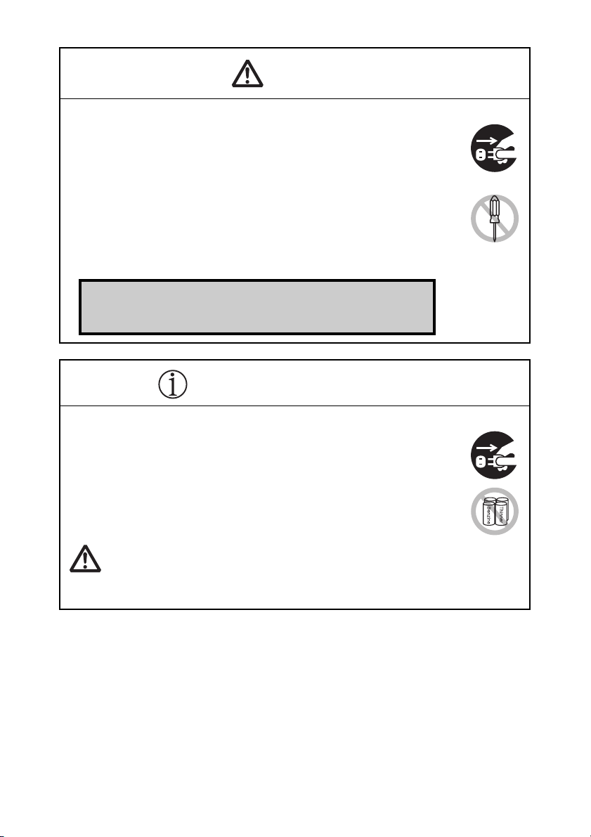
This symbol denotes a request to unplug the printer from the wall outlet.
This symbol is used to indicate that the power supply must be grounded.
This symbol is used to indicate useful information, such as procedures,
instructions or the like.
This symbol is used to indicate prohibited actions.
—2—
Page 7
PRECAUTIONS ON PRINTER INSTALLATION
WARNING
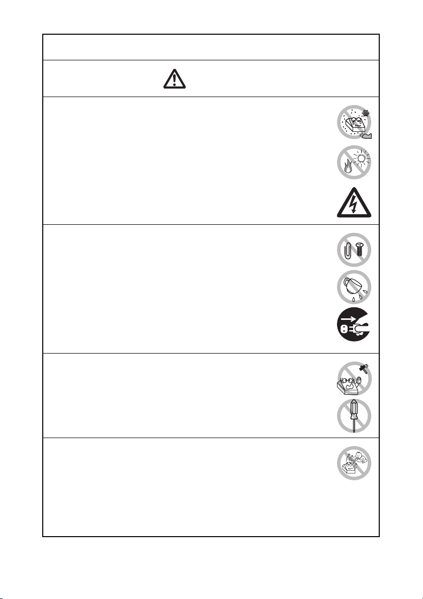
Do not use or store this product in a place where it will be exposed to:
* Flames or moist air.
* Direct sunlight.
* Hot airflow or radiation from a heating device.
* Salty air or corrosive gases.
* Ill-ventilated atmosphere.
* Chemical reactions in a laboratory.
* Airborne oil, steel particles, or dust.
* Static electricity or strong magnetic fields.
• Neglecting these warnings may result in printer failure, overheating,
emission of smoke, fire, or electric shock.
Do not drop any foreign object nor spill liquid into the printer. Do not
place any object on the printer either.
Do not drop any metallic object such as paper clips, pins or screws
into the printer.
Do not place a flower vase, pot, or anything containing water on the
printer.
Do not spill coffee, soft drinks, or any other liquid into the printer.
Do not spray insecticide or any other chemical liquid over the printer.
• Dropping a metallic foreign object into the printer, may cause printer
failure, fire, or electric shock. Should it occur, immediately turn the
printer off, unplug it from the supply outlet, and call your local Citizen
Systems dealer.
Do not handle the printer in the following ways:
Do not subject the printer to strong impacts or hard jolts (e.g., being
stepped on, dropped or struck).
Never attempt to disassemble or modify the printer.
• Neglecting to handle properly may result in printer failure,
overheating, emission of smoke, fire, or electric shock.
Install, use, or store the printer out of the reach of children.
• Electric appliances could cause an unexpected injury or accident if
they are handled or used improperly.
• Keep the power cord and signal cables out of the reach of children.
Also children should not be allowed to gain access to any internal
part of the printer.
• The plastic bag the printer came in must be disposed of properly or
kept away from children. Wearing it over the head may lead to
suffocation.
—3—
Page 8
CAUTION
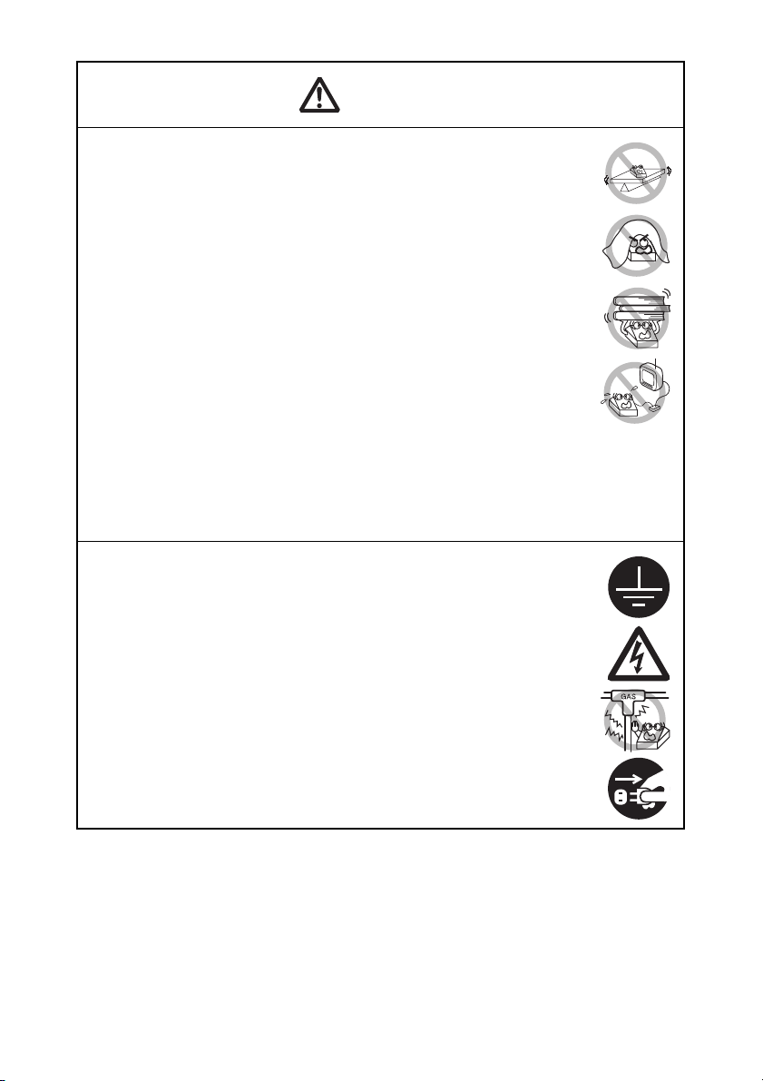
Do not use the printer under the following conditions.
Avoid locations subject to vibration or instability.
Avoid locations where the printer is not level.
• The printer may fall and cause an injury.
• The quality of printing may deteriorate.
Do not obstruct the printer’s air vents.
Do not place anything on the printer.
Do not cover or wrap the printer in cloth or blankets.
• Doing so could cause heat to build up and deform the case or start a
fire.
Avoid using the printer near a radio or TV set or from supplying it from
the same electric outlet as these appliances.
Avoid using the printer interconnected with a cable or cord that has
no protection against noise. (For interconnections, use shielded or a
twisted pair of cables and ferrite cores, or other anti-noise devices.)
Avoid using the printer with a device that is a strong source of noise.
• The printer may have an adverse effect on nearby radio or TV
transmissions. There may also be cases when nearby electrical
appliances adversely influence the printer, causing data errors or
malfunction.
Installed in any orientation other than those specified.
• Malfunction, failure, or electric shock may result.
Connect the printer to a ground.
• Electric leakage may cause an electric shock.
Do not connect the printer’s ground to any of the following:
* Gas piping
• A gas explosion could result.
* Telephone line ground
* Lightning rod
• If lightning strikes a large surge of current may cause fire or
shock.
* Water pipes
• Plastic water pipes should not be used for grounding. (Those
approved by a Waterworks Department may be used.)
Before connecting or disconnecting the grounding lead to or from the
printer, always unplug it from the electric outlet.
—4—
Page 9

PRECAUTIONS IN HANDLING THE PRINTER
WARNING
Please observe the following precautions for power source and power
cord:
Do not plug or unplug the power cord with a wet hand.
Use the printer only at the specified supply voltage and frequency.
Use only the specified AC adapter with the printer.
Check to make sure that the supply outlet from which the printer is
powered has a sufficient capacity.
Do not supply the printer from a power strip or current tap shared with
other appliances.
Do not plug the power cord into an electric outlet with dust or debris
left on the plug.
Do not use a deformed or damaged power cord.
Do not move the printer while its power is on.
• Neglecting to handle it properly may result in printer failure, emission
of smoke, fire, or electric shock.
• An overload may cause the power cord to overheat, catch fire, or the
circuit breaker to trip.
Do not allow anything to rest on the power cord. Do not place the
printer where the power cord may be stepped on.
Do not use or carry the printer with its power cord bent, twisted, or
pulled.
Do not attempt to modify the power cord unnecessarily.
Do not place the power cord near any heating device.
• Neglecting these cautions may cause wires or insulation to break,
which could result in electric leakage, electric shock, or printer failure.
If the power cord sustains damage, contact your Citizen Systems
dealer.
Do not leave things around the electric outlet.
Supply power to the printer from a convenient electric outlet, readily
accessible in an emergency.
• Pull the plug to immediately shut it down in an emergency.
Insert the power plug fully into the outlet.
If the printer will not be used for a long time, disconnect it from its
electric outlet.
Hold the plug and connector when plugging or unplugging the power
cord or signal cable after turning off the printer and the appliance
connected to it.
—5—
Page 10
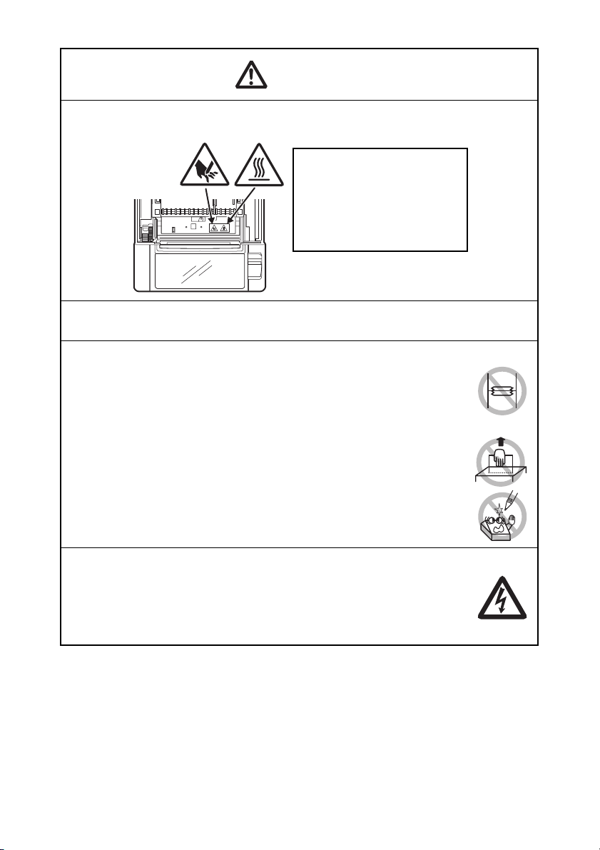
CAUTION
Caution label is attached in the position shown in the following figure. Carefully read
the handling precautions before using the printer.
THIS LABEL INDICATES THE
RISK OF BURNS DUE TO THE
HIGH TEMPERATURE OF THE
PRINT HEAD AND A RISK OF
BEING CUT BY THE MANUAL
AND AUTO CUTTERS WHILE
THE PAPER COVER IS OPEN.
Do not transport this printer with the paper roll inside.
• Printer failure or damage may occur.
To prevent possible malfunction or failure observe the following.
Avoid operating the printer without paper properly loaded.
Avoid the use of paper not complying with specifications.
• May result in poor print quality.
Avoid using torn pieces of paper or paper spliced with plastic adhesive
tape.
Avoid forcibly pulling already loaded paper by hand.
Avoid using a sharp pointed device to operate panel buttons.
Be sure to firmly insert the cable plugs into their mating sockets.
• A cross connection may damage the printer’s internal electronics or
the host system’s hardware.
Only use the printer with devices that have designated solenoid
specifications for the cash drawer interface connector.
• Neglecting this caution may result in malfunction or failure.
—6—
Page 11
CAUTION
To prevent injury and printer failures from worsening, observe the following:
While the paper cover is open, be careful to not touch the manual
cutter that is in the paper eject slot.
Do not touch the printing surface of the thermal head.
Do not touch any of the moving parts (e.g., paper cutter, gears, active
electric parts) while the printer is working.
In case of trouble do not attempt to repair the printer. Ask Citizen
Systems service for repair.
Be careful that the covers do not pinch your hands or fingers.
Be careful of the sharp edges on the printer. Do not allow them to
injure you or damage property.
• May result in electric shock, burn, or injury.
If the printer emits smoke, an odd smell, or unusual noise while
printing, immediately abort the current print session and
unplug the printer from the electric outlet.
DAILY MAINTENANCE
Observe the following precautions for daily maintenance.
When cleaning the printer, always turn it off and unplug it from the
electric outlet.
Use a soft, dry cloth for cleaning the surface of the printer case.
For severe stains, use a soft cloth slightly dampened with water.
Never use organic cleaning solvent such as alcohol, paint thinner,
trichloroethylene, benzene, or ketone. Never use a chemically
processed cleaning cloth.
To remove paper dust, use a soft brush.
CAUTION
• The thermal head is at a dangerously high temperature immediately after printing.
Allow it to cool off before starting maintenance work.
Visit the following site to get documentation, drivers, utilities, and other
information.
http://www.citizen-systems.co.jp/english/support/index.html
—7—
Page 12

THE TABLE OF CONTENTS
1. GENERAL OUTLINE ....................................................................9
1.1 Features .......................................................................................... 9
1.2 Unpacking .................................................................................... 10
1.3 Model Classification .................................................................... 10
1.4 Basic Specifications..................................................................... 11
2. EXPLANATION OF PRINTER PARTS .......................................12
2.1 Printer Appearance...................................................................... 12
2.2 Inside the paper cover................................................................. 15
2.3 Other Built-in Functions .............................................................. 16
3. SETUP ........................................................................................17
3.1 Connecting the AC Power Cord.................................................. 17
3.2 Connecting Interface Cables ....................................................... 18
3.3 Connecting the Cash Drawer ...................................................... 19
3.4 Precautions for Installing the Printer ......................................... 21
3.5 Partition for Paper Roll ................................................................ 22
3.6 Setting the DIP Switch on the Serial Interface Board ............... 23
3.7 Adjusting the Paper Near-end Sensor ....................................... 24
3.8 Setting Paper Thickness.............................................................. 25
3.9 Loading Paper.............................................................................. 26
3.10 Attaching the Power Switch Cover........................................... 27
3.11 Attaching the Interface Cover ................................................... 28
3.12 Removing the Interface Cover .................................................. 28
4. MAINTENANCE AND TROUBLESHOOTING........................... 29
4.1 Periodic Cleaning......................................................................... 29
4.2 Clearing a Cutter Lock (1)............................................................ 30
4.3 Clearing a Cutter Lock (2)............................................................ 31
4.4 Self-printing ................................................................................. 32
4.5 Hexadecimal Dump Printing....................................................... 33
4.6 Error Messages ............................................................................ 34
5. OTHER .......................................................................................36
5.1 External Views and Dimensions................................................. 36
5.2 Printing Paper .............................................................................. 37
5.3 Manual Setting of Memory Switches ........................................ 38
—8—
Page 13

1. GENERAL OUTLINE
The CT-S601 line thermal printer series is designed for use with a broad array
of terminal equipment including data, POS, and kitchen terminals.
These printers have extensive features so they can be used in a wide range of
applications.
1.1 Features
z High-speed (200 mm/s) printing.
z Design so compact it can be installed anywhere (maximum 3-inch (83-mm)
paper roll size)
z Choose from two models with either 3-inch (83/80 mm) or 2-inch (60/58 mm)
wide paper rolls.
z Built-in power supply or AC adapter types available
z Printer status and errors indicated by LED and a buzzer
z Equipped with a fast and quiet cutter
z Easy to clear cutter jams
z Interchangeable interface
z Built-in cash drawer kick-out interface
z Memory switches make customization possible
z Store user-defined characters and logos on user memory
z Barcode and 2D barcode printing supported
z 2-color printing supported (when specified paper used)
z Driver and utility software included
—9—
Page 14
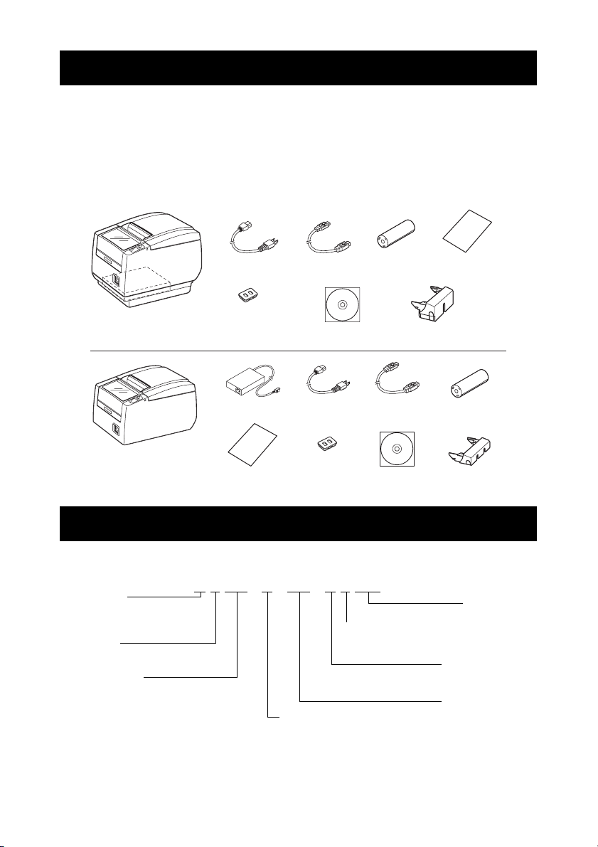
1.2 Unpacking
Make sure the following items are included with your printer.
z Printer: 1
z Interface cover: 1
z AC power cord: 1
z Power switch cover: 1
z Sample paper roll: 1 roll
z CD-ROM: 1
z Quick Start Guide: 1
z AC adapter
z USB cable
Notes:
*1: CT-S601A only
*2: USB interface types only
In designated markets
*1:1
*2:1
Interface coverCD-ROM
Quick Start
Guide
Sample
paper roll
Interface cover
CT-S601S
(Built-in power supply type)
36AD3 AC adapter built in
CT-S601A
(AC adapter type)
AC power cord
Power switch
cover
AC adapter
(36AD2)
Quick Start
Guide
USB cable
AC power
cord
Power switch
cover
Sample
paper roll
USB cable
CD-ROM
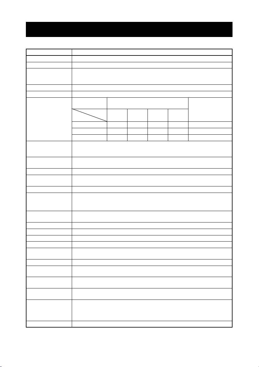
1.3 Model Classification
Model numbers indicate printer features according to the following system.
Power supply
DC:No power source
S: Built-in power supply type
A: AC adapter type
Paper width
3: 3 inch (80/83 mm)
2: 2 inch (58/60 mm)
Note:
*: AC power cord, serial I/F screw, firmware and other specifications vary according to markets.
CT - S601S 3 RS E - BK - P L M1
Interface
PA: Parallel
RS: Serial RS-232C
UB: USB only
UH: USB with hub
ET: Ethernet (standard type)
ES: Ethernet (multi-function type)
UP: Powered USB
*
Market:
J: Japanese E: Europe/Asia
U: North America
C: China
—10—
Label
:No
L: Label printing
BM sensor
:No
M1: Left side
M2: Right
side
PNE sensor
:No
P: PNE sensor
Body case color
WH: Cool white
BK: Black
Page 15
1.4 Basic Specifications
Item Specifications
Model CT-S601
Print method Line thermal dot print method
Print width
Dot density 8 × 8 dots/mm (203 dpi)
Print speed 200 mm/s (fastest, print density 100%), 1600 dot-lines/s
Number of print
columns
Character size
Character type Alphanumeric, international, PC437/850/852/857/858/860/863/864/865/866/
User memory 384 KB (capable of storing user-defined characters and logos)
Bar code types UPC-A/E, JAN (EAN) 13/8 columns, ITF, CODE39, CODE128, CODABAR (NW-7),
Line spacing 4.25 mm (1/6 inch) (changeable using commands)
Paper roll
Interface Serial (RS-232C compliant), parallel (IEEE 1284 compliant), USB, USB with
Cash drawer kick-out Supports 2 cash drawers
Buffer size 4 k bytes/45 bytes
Supply voltage DC 24 V ±5%
Power consumption Approximately 45 W (normal printing), 3 W (standby)
AC adapter
(36AD2, 36AD3)
Weight CT-S601S: Approx. 2 kg, CT-S601A: Approx. 1.6 kg
Outside dimensions CT-S601S: 145 (W) × 192 (D) × 148 (H) mm
Operating temperature
and humidity
Storage temperature
and humidity
Reliability Print head life: 150 km, 200 million pulses (at normal temperature and
Safety standard
*1 80 mm/640 dots, 72 mm/576 dots, 64 mm/512 dots, 54.5 mm/436 dots,
54 mm/432 dots, 52.5 mm/420 dots, 48 mm/384 dots, 45 mm/360 dots,
48.75 mm/390 dots, 68.25 mm/546 dots
*2
—
Paper width
Font
Maximum number of characters
(columns)
83 mm 80 mm 60 mm 58 mm
Dot configuration
Font A 53483635 12 × 24
Font B 71644846 9 × 17
Font C 80725452 8 × 16
*3 Font A: 1.50 × 3.00 mm
Font B: 1.13 × 2.13 mm
Font C: 1.00 × 2.00 mm
WPC1252/katakana/Thai code 18
CODE93, PDF417, QR Code
Paper roll: 83 mm/80 mm/60 mm/58 mm × maximum φ83 mm
Paper thickness: 65-75 μm (core tube diameter: inner 12 mm/outer 18 mm)
+0
-1
+0
-1
+0
-1
+0
-1
75-85 μm (core tube diameter: inner 25.4 mm/outer 32 mm)
hub, Ethernet, Powered USB
*4
Rated input: AC 100 to 240 V, 50/60 Hz, 150 VA
Rated output: DC 24 V, 2.1 A
CT-S601A: 145 (W) × 192 (D) × 120 (H) mm
5 to 45°C, 10 to 90% RH (no condensation)
-20 to 60°C, 10 to 90% RH (no condensation)
humidity using recommended paper)
Auto cutter life: 2 million cuts (at normal temperature/humidity, using
recommended paper and paper thickness)
*5 UL, C-UL, FCC Class A, TÜV-Bauart, CE Marking
(dots)
—11—
Page 16
Notes:
*1: When paper width is 83, 80, 60, or 58 mm.
*2: The number of printable columns is selected using a memory switch.
The number of columns noted in this table refer to typical models. The number of columns varies
depending on specifications.
*3: Characters appear small because the dimensions include a blank area surrounding each
character.
*4: The 36AD2 is the AC adapter packaged as an accessory with the CT-S601A.
The 36AD3 is the AC adapter built in to the CT-S601S.
*5: Compliant if the Citizen Systems AC adapter (36AD2/36AD3) is used.
2. EXPLANATION OF PRINTER PARTS
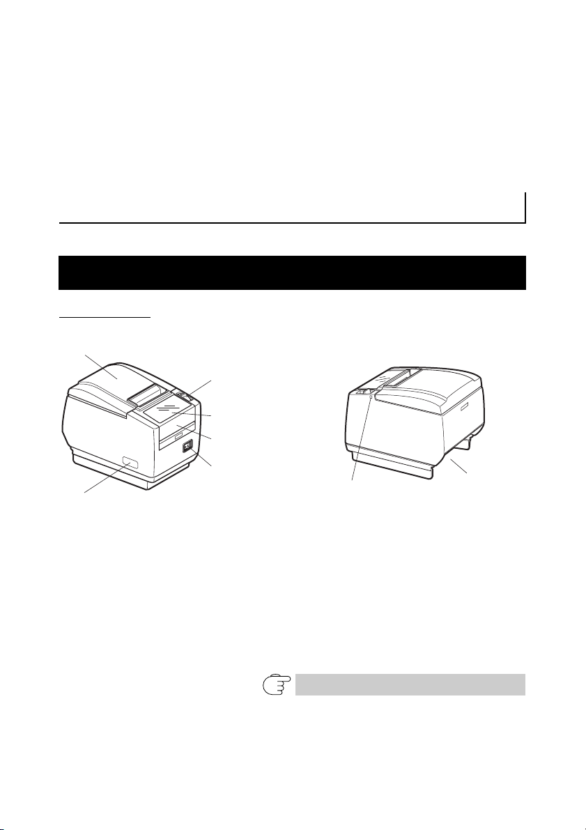
2.1 Printer Appearance
Names of parts
Paper cover
Cover open lever
Operation panel
Front cover
Power switch
Maintenance cover
(Front view) (Rear view)
z Paper cover
Open to load paper.
z Cover open lever
Use this lever to open the paper cover.
z Front cover
Open and close this cover to clear a cutter lock.
Refer to 4.3 Clearing a Cutter Lock (2)
z Front cover release button
Press this button to open the front cover.
—12—
Front cover
release button
Rear connectors
Page 17
z Power switch
Press this button to turn the power on or off.
z Maintenance cover
Not applicable for this product.
CAUTION
Do not open the maintenance cover.
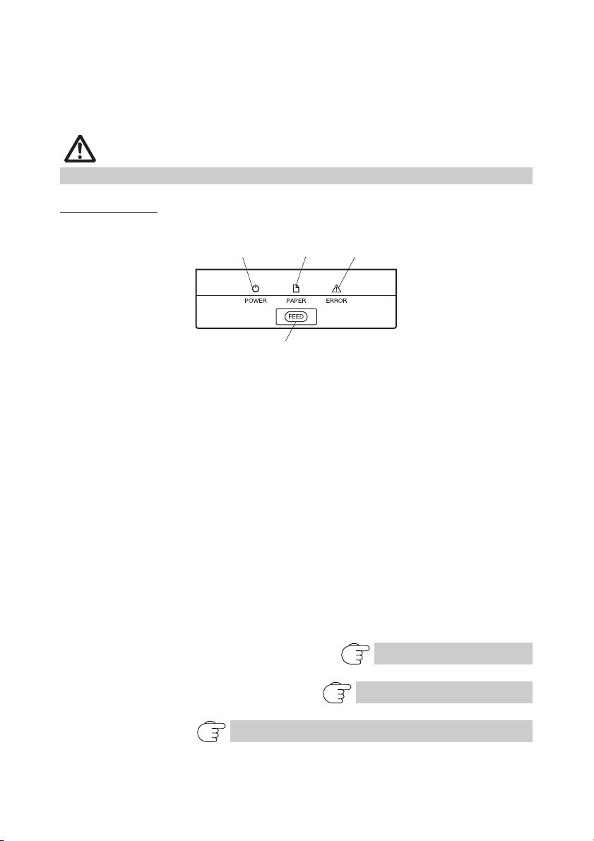
Operation panel
POWER LED (green)
PAPER LED
(orange)
FEED button
ERROR LED (red)
z POWER LED (green)
Lights when the power is on, turns off when the power is off.
Flashes when data is incoming or a memory error has occurred.
z PAPER LED (orange)
Lights orange when paper is low (paper near-end) or there is no paper (paper
end).
z ERROR LED (red)
Flashes if the print head is hot, the paper cover is open, a cutter lock occurs,
and so forth.
z FEED button
Press this button to feed paper.
In case of a cutter lock, remove the cause of the lock, close the paper cover,
and then press the FEED button.
The printer enters the mode for setting memory switches and running selfprinting.
Refer to 4.4 Self-printing
Refer to 4.6 Error Messages
Refer to 5.3 Manual Setting of Memory Switches
—13—
Page 18

Rear connectors
Interface connector
(serial, parallel, USB, etc.)
Cash drawer
kick-out
connector
AC inlet (built-in power supply type)
Power connector (AC adapter type)
z Interface connector (serial, parallel, USB, etc.)
Connects to the interface cable.
The serial interface board is equipped with a DIP switch.
z Cash drawer kick-out connector
Connects to the cable from the cash drawer.
z Power connector (AC adapter type)
Connects to the AC adapter cable.
z AC inlet (built-in power supply type)
Connects to the AC power cord.
—14—
Page 19
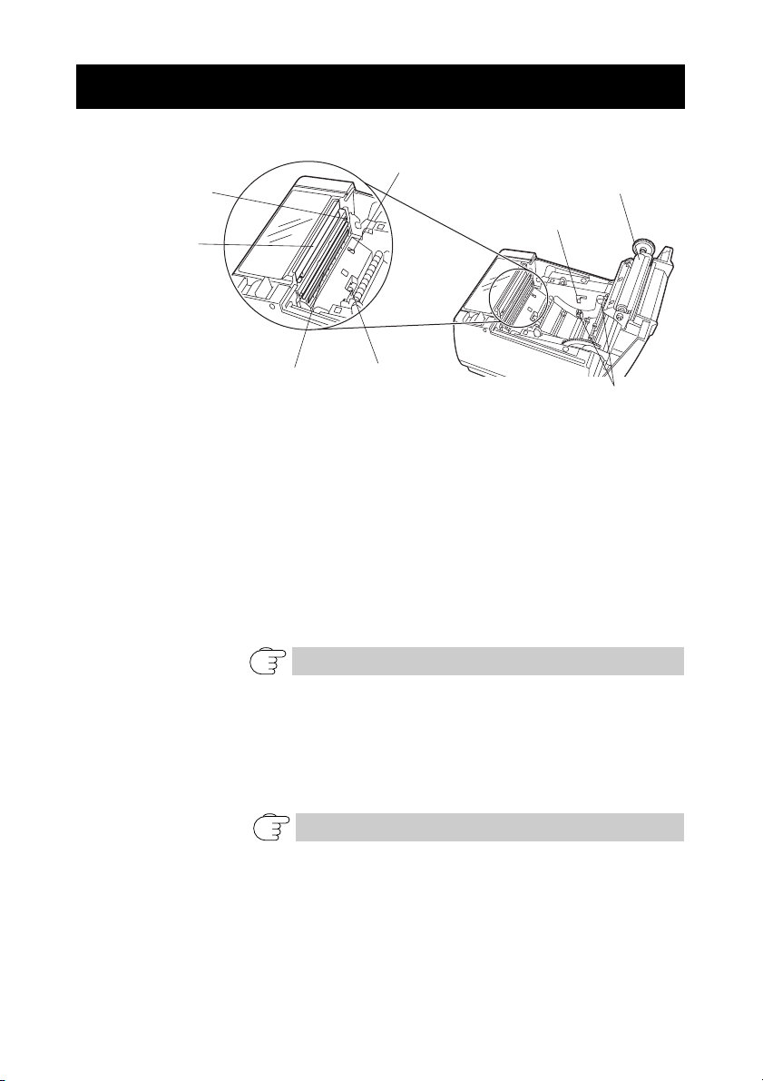
2.2 Inside the paper cover
Paper-end sensor
(PE sensor)
Auto cutter
Manual cutter
Platen
Button to change paper
near-end sensor
Print head (thermal)
Paper thickness
selection lever
Paper near-end sensor
(PNE sensor)
z Platen
Feeds the paper.
z Paper near-end sensor (PNE sensor)
Detects when the paper is near the end of the roll. Adjust the position of the
sensor to determine when it detects the end of the paper is near.
z Button to change paper near-end sensor
Change the position of the paper near-end sensor to match the paper being
used.
Refer to 3.7 Adjusting the Paper Near-end Sensor
z Manual cutter
For cutting the paper manually when printing is finished.
z Auto cutter
Automatically cuts the paper when printing is finished.
Refer to 5.3 Manual Setting of Memory Switches
z Print head (thermal)
Prints characters and graphic data on paper (paper rolls).
z Paper end sensor (PE sensor)
Detects when there is no paper. Printing stops when this sensor detects there
is no paper.
—15—
Page 20

z Paper thickness selection lever
Use this lever to select regular or thick paper according to the thickness of the
paper being loaded.
CAUTION
Do not change the position of the paper thickness selection lever from the factory
setting.
Refer to 3.8 Setting Paper Thickness
2.3 Other Built-in Functions
z Buzzer
Buzzes when errors occur or when operations or command operations are
performed.
Refer to 4.6 Error Messages
z User memory
You can save user-defined logo and character data in this memory. Data
remains stored in this memory even if the printer is turned off. For
information on how to save data, refer to the Command Reference.
z Memory switch
Setting of various kinds of functions can be stored in memory. Settings
remain stored in the memory even if the printer is turned off.
—16—
Page 21
3. SETUP
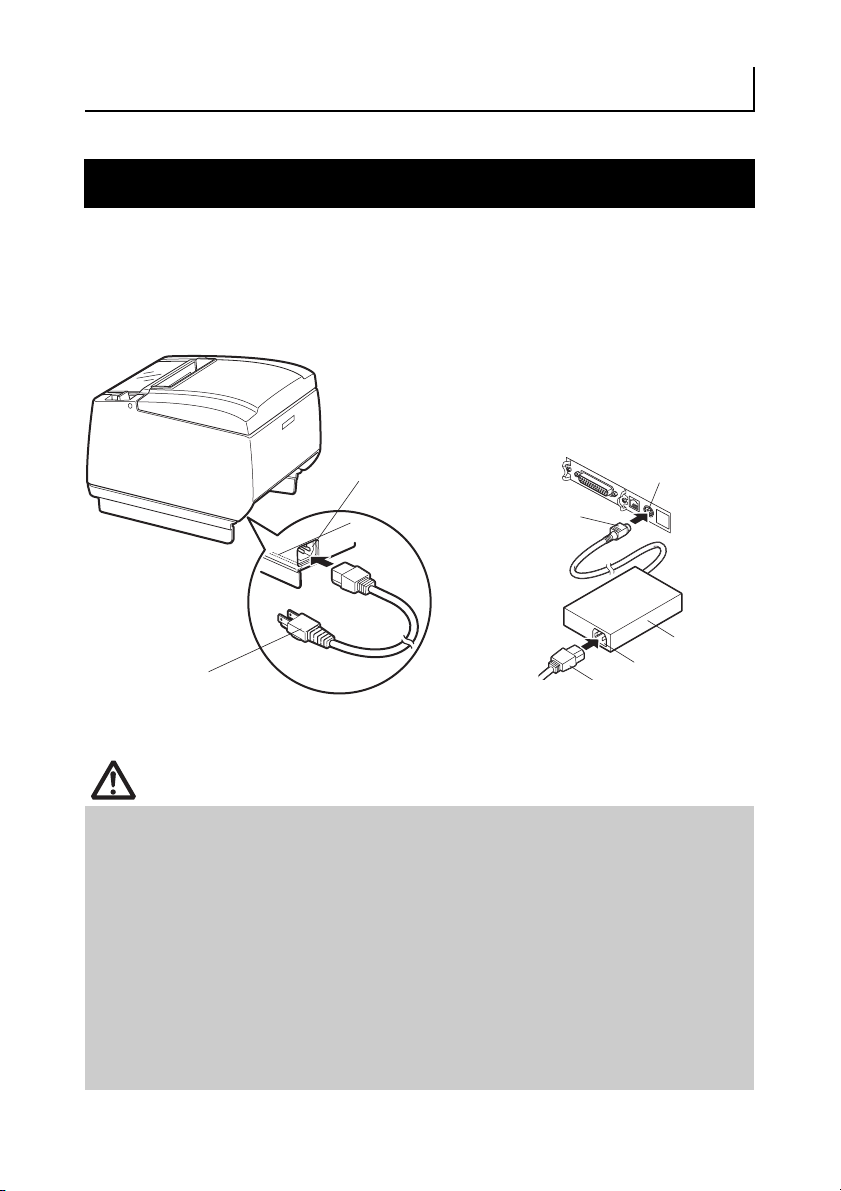
3.1 Connecting the AC Power Cord
1. Turn off the power.
2. z For the built-in power type printer, connect the AC power cord to the AC inlet, and
insert the plug into an electric outlet.
z For the AC adapter type printer, connect the cable connector of the AC adapter to
the power connector. Next, connect the AC power cord to the AC inlet, and insert
the plug into an electric outlet.
AC inlet
Cable connector
AC power cord
Built-in power supply type
Power connector
AC adapter
AC inlet
AC power cord
AC adapter type
CAUTION
Use only an AC adapter that complies with the specified ratings.
Always hold the AC adapter’s cable connector by the connector when removing or
inserting it.
Use an AC power source that does not also supply power to equipment that
generates electromagnetic noise.
Pulling on the AC power cord may damage it, cause a fire, electric shock, or break a
wire.
If a lightning storm is approaching, unplug the AC power cord from the electric outlet.
A lightning strike may cause a fire or electric shock.
Keep the AC power cord away from heat generating appliances. The insulation on the
AC power cord may melt and cause a fire or electric shock.
If the printer is not going to be used for a long time, unplug the AC power cord from
the electric outlet.
Place the AC power cord so that people do not trip on it.
—17—
Page 22
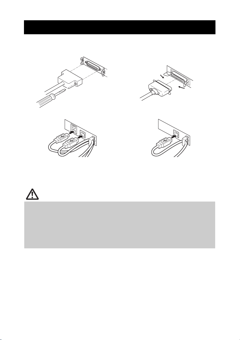
3.2 Connecting Interface Cables
1. Turn off the power.
2. Orient the interface cable correctly and insert it into the interface connector.
Serial interface
USB interface (hub type) USB interface
Parallel interface
Ethernet and Powered USB interfaces are available as options in addition to
those listed here.
CAUTION
Always unplug the AC adapter from the printer before connecting the printer to a
Powered USB interface. Failure to do so may damage the host PC. For information
about installing a Powered USB interface, contact your Citizen Systems dealer.
When disconnecting the cable, always hold the connector.
Be careful not to insert the USB interface cable into the cash drawer kick-out
connector.
To connect more than one printer to a single computer via a USB interface you must
change the serial number of the USB interface.
—18—
Page 23
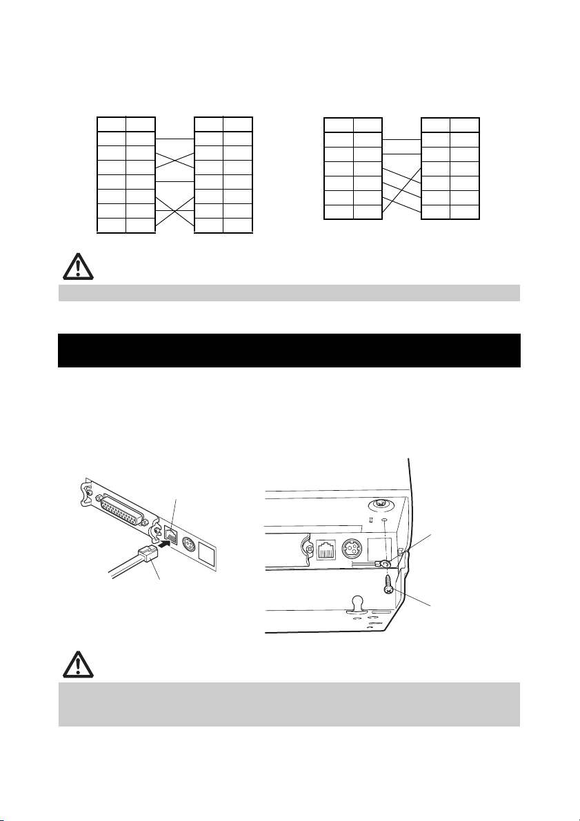
Use a serial interface cable with the connection layout shown below.
25-pin - 25-pin cable
9-pin - 25-pin cable
PC Printer
Signal
Pin Pin
FG 1 1 FG
TXD 2 2 TXD
RXD 3 3 RXD
CTS 5 4 RTS
DSR 6 6 DSR
SG 7 7 SG
DTR 20 20 DTR
Signal
PC Printer
Signal
Pin Pin
RXD 2 2 TXD
TXD 3 3 RXD
DTR 4 4 RTS
SG 5 6 DSR
DSR 6 7 SG
CTS 8 20 DTR
Signal
CAUTION
Place the interface cable so people do not trip on it.
3.3 Connecting the Cash Drawer
1. Turn off the power.
2. Confirm the orientation of the cash drawer kick-out cable connector and connect it
to the cash drawer kick-out connector at the back of the printer.
3. Remove the screw for the ground wire.
4. Screw the cash drawer’s ground wire to the body of the printer.
Cash drawer kick-out
connector
Ground wire
Cash drawer kick-out cable
connector
Screw for ground
wire
CAUTION
Connect only the cash drawer kick-out cable connector to the cash drawer kick-out
connector. (Do not connect a telephone line.)
Signals cannot be output from the cash drawer kick-out connector while printing.
—19—
Page 24
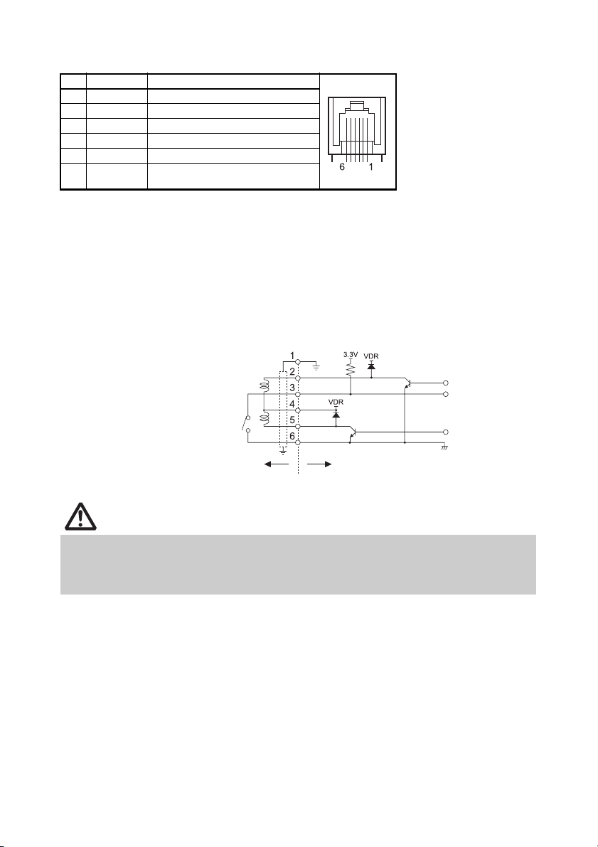
(1) Connector pin configuration
No. Signal Function
1 FG Frame ground Connector used:
2 DRAWER1 Cash drawer 1 drive signal
3 DRSW Cash drawer switch input
4 VDR Cash drawer drive power supply
5 DRAWER2 Cash drawer 2 drive signal
6 GND Signal ground (common ground on
circuits)
TM5RJ3-66 (Hirose) or
equivalent
Applicable connector:
TM3P-66P (Hirose) or
equivalent
(2) Electric characteristics
1) Drive voltage: 24 VDC
2) Drive current: Approx. 1 A max. (not to exceed 510 ms.)
3) DRSW signal: Signal levels: “L” = 0 to 0.8 V, “H” = 2 to 3.3 V
(3) DRSW signal
DRSW signal status can be tested with the DLE+EOT, GS+a, or GS+r
command or at pin 34 on the parallel interface port.
(4) Drive circuit
Cash drawer kick-out connector
Shielded
Cash drawer open/
close switch
Cash drawer Printer
CAUTION
Cash drawers 1 and 2 cannot be operated at the same time.
The solenoid used for the cash drawer should be 24 Ω or more. Do not allow the
electric current to exceed 1 A. Excessive current could damage or burn out the
circuits.
—20—
Page 25
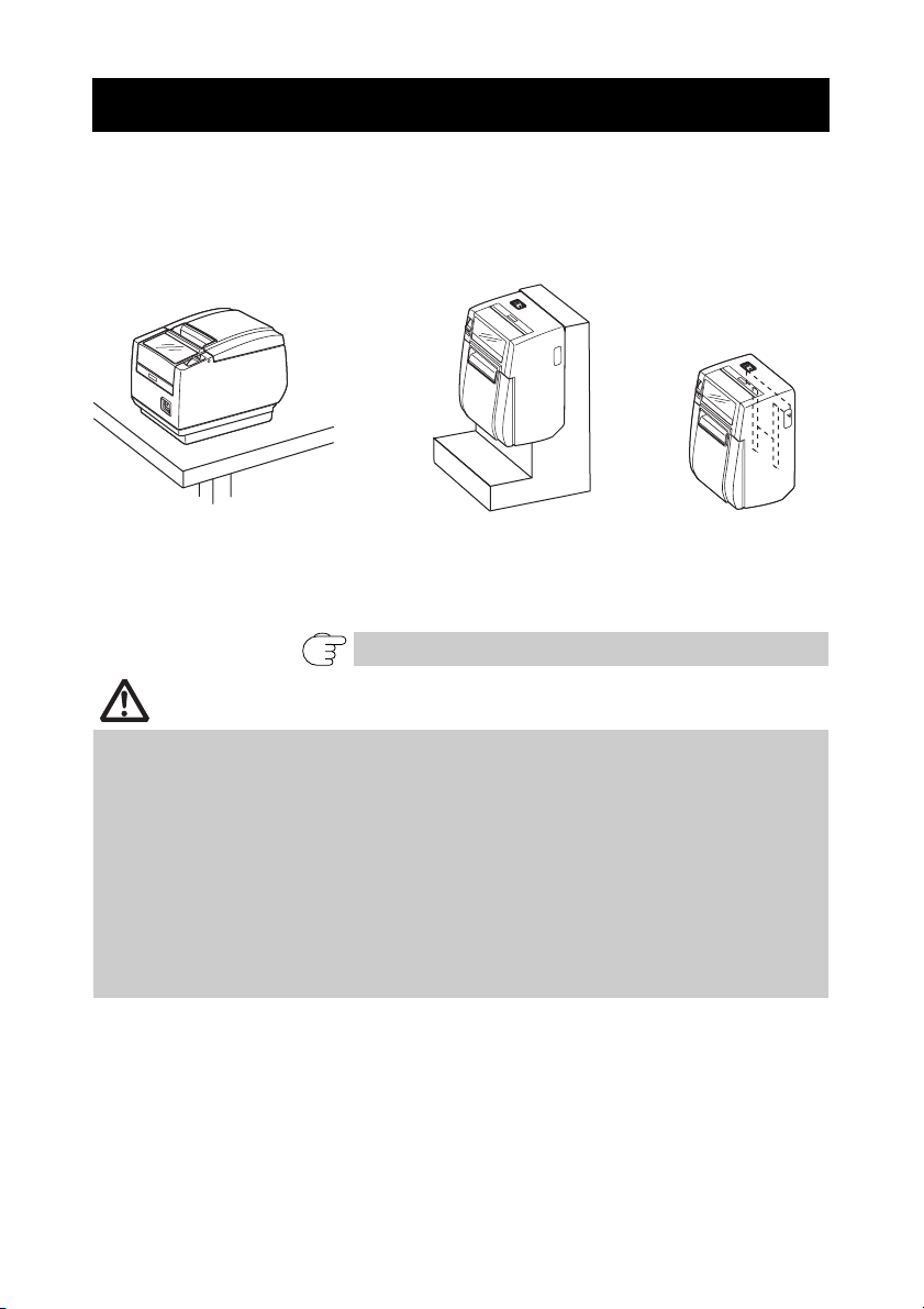
3.4 Precautions for Installing the Printer
The printer can be used horizontally, vertically, or installed on a wall. However,
the CT-S601S (built-in power supply type) cannot be used vertically or installed
on a wall.
Use the optional stand for vertical applications, and the optional brackets for
wall installations. Please refer to the manual for further details.
Horizontal position
Vertical position Wall installation
Change the paper near-end sensor settings for vertical and wall installations.
(The factory setting for the paper near-end sensor is for horizontal installations.)
Refer to 3.7 Adjusting the Paper Near-end Sensor
CAUTION
Do not use the printer under the following conditions.
Locations subject to vibration or instability.
Locations that are very dirty or dusty
Locations where the printer is not level.
• The printer may fall and cause an injury.
• The quality of printing may deteriorate.
Oriented other than as specified.
• The printer may malfunction, be damaged, or cause an electric shock.
Precautions for horizontal installations
Do not set cutting to full cut. Doing so may cause cutter jams.
Precautions for vertical/wall installations
Adjust the paper near-end sensor.
—21—
Page 26
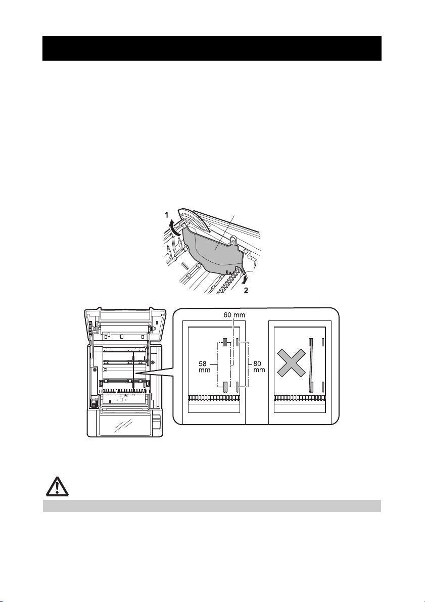
3.5 Partition for Paper Roll
Set the partition to the width of the paper roll you are loading.
The partition is set at the factory to the position shown below.
z For 3-inch type: 80-mm wide paper roll
z For 2-inch type: 58-mm wide paper roll
1. Turn off the power.
2. Press the cover open lever.
3. Open the paper cover.
4. Set the partition in a slot that matches the size of the paper roll you are using.
However, to use an 83-mm wide paper roll, remove the partition.
5. Refer to “5.3 Manual Setting of Memory Switches” to change the paper width
settings.
Partition
*1
*1
*2
Notes:
*1: 2-inch type (58/60 mm)
*2: 3-inch type (80/83 mm)
CAUTION
Make sure the partition is not slanted when setting it for 58-mm or 60-mm paper rolls.
—22—
Page 27
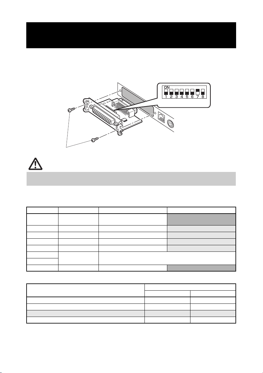
3.6 Setting the DIP Switch on the Serial Interface Board
1. Turn off the printer and unplug the power cord from the electric outlet.
2. Remove the mounting screws of the serial interface board.
3. Remove the serial interface board from the printer.
4. Set the DIP switch according to the following table.
DIP switch
Serial interface board mounting screws
CAUTION
When setting the DIP switch, do not remove any screws except the serial interface board
mounting screws.
The function of each switch is shown below. (Shaded values are factory
settings. However, factory settings differ depending on the destination market.)
Switch no. Function ON OFF
1 Communication
condition setting
2 Hand shake XON/XOFF
3 Bit length 7 bits
4 Parity check Yes
5 Parity selection Even parity
6
Baud rate
selection
7
8 INIT Reset
According to DIP switch settings
Refer to table below.
According to memory switch
settings
DTR/DSR
8 bits
No
Odd parity
Invalid
Baud rate selection
Baud rate (bps)
2400 OFF OFF
4800 ON OFF
9600 OFF ON
19200 ON ON
Switch no.
67
When switch no. 1 is set to OFF, you can use a command or a memory switch
to select 1200, 38400, 57600, or 115200 bps.
—23—
Page 28
3.7 Adjusting the Paper Near-end Sensor
Change the settings of the paper near-end sensor to set the position at which
the near-end of the paper is detected.
1. Use a pointed object, such as a pen, to gently press the button to change the paper
near-end sensor.
2. Press and hold down the button while moving the paper near-end sensor up, down,
right and left. The sensor positions are shown below for the various diameters of the
paper roll used.
(Unit: mm)
Sensor position Diameter when detected as near end Diameter of core of paper roll used
A, a φ31 φ18
B
*, b φ23 φ18
C Paper near-end sensor function is off
Note:
*: Position of sensor when shipped from factory. However, factory settings differ depending on the
destination market.
CAUTION
The amount of paper remaining on the roll (diameter of the roll) depends on the type
of paper used.
The paper roll diameters in the table are guidelines.
Button to change paper
near-end sensor
(“A” and “B” are for horizontal installations, and “a” and “b” are for vertical or
wall installations.)
—24—
Page 29
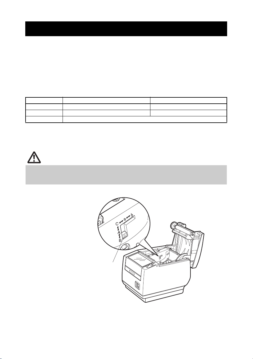
3.8 Setting Paper Thickness
Set the paper thickness selection lever to the thickness of the paper. (Thick
paper can only be used with the label-printing model)
To get the best print quality, do not change the factory settings unless printing
on thick paper or there is a problem with the print density.
Refer to 1.3 Model Classification
1. Turn off the power.
2. Press the cover open lever.
3. Open the paper cover.
4. Set the paper thickness selection lever to A for thick paper or B for regular paper.
Gently press on the side of the lever with a pointed object, such as a pen, to
move the paper thickness selection lever.
Paper thickness
selection lever
A: Thick paper 85 μm - 150 μm
B: Regular paper 65 μm - 85 μm (Factory setting)
—25—
Page 30
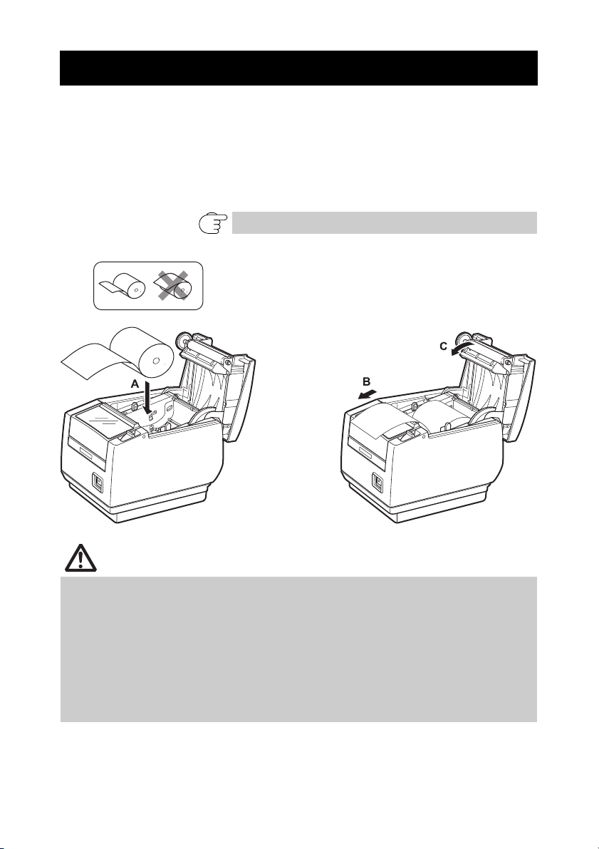
3.9 Loading Paper
1. Press the cover open lever while the power is on.
2. Open the paper cover.
3. Load the paper roll so that the printable side of the paper is facing down, as shown
by arrow A.
4. Pull a few cm of paper straight out in the direction of arrow B.
5. Close the paper cover in the direction of arrow C until you hear a click. Paper is fed
and cut automatically, if the factory settings are set.
Refer to 5.3 Manual Setting of Memory Switches
CAUTION
Always use the specified types of paper rolls.
Confirm that the paper roll is set correctly.
If the paper is skewed and not coming straight out of the paper cover, open it and
straighten the paper.
Always pull a few cm of paper straight out of the printer if you open the paper cover
while paper is loaded.
Press on the center of the paper cover to close it securely.
Be careful of paper cuts while loading the paper.
Do not touch the print head, manual cutter, or auto cutter while the paper cover is
open. Doing so may cause a burn or cut.
—26—
Page 31

3.10 Attaching the Power Switch Cover
Attach this cover to prevent the power switch from being used.
1. Press the power switch cover onto the power switch compartment until it clicks.
Power switch cover
Put a screwdriver or other pointed object into the grooves on the power switch
cover to remove it.
—27—
Page 32

3.11 Attaching the Interface Cover
Attach the interface cover to the back of the printer.
The shape of the interface cover is different depending on the type of power
source.
1. Press the interface cover as shown in the diagram until you hear it click.
CT-S601S
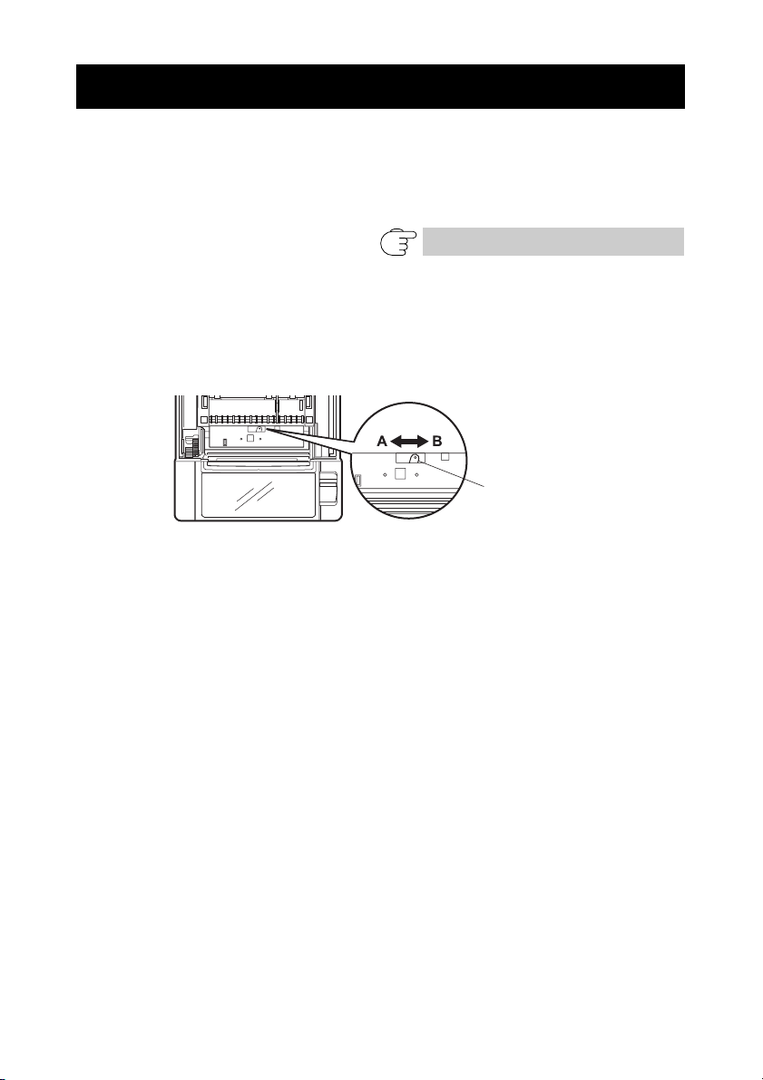
3.12 Removing the Interface Cover
Press in on both sides at the point indicated by A to remove the interface cover.
CT-S601S
—28—
Page 33

4. MAINTENANCE AND TROUBLESHOOTING
4.1 Periodic Cleaning
A dirty print head or platen may reduce printing quality or cause malfunctions.
Also, if paper dust collects on the sensor’s protective sheet, paper cannot be
detected correctly. We recommend cleaning the printer periodically (every 2 to
3 months) as shown below.
1. Turn off the power.
2. Press the cover open lever.
3. Open the paper cover. Wait a few minutes until the print head cools.
4. Use a cotton swab dampened with ethyl alcohol to wipe off any dirt and dust that is
on the print head and platen.
5. Use a cotton swab dampened with a little water to wipe off the sensor’s protective
sheet.
Make sure there are no water drops on the cotton swab before wiping.
Platen
Print head
Sensor’s protective sheet
CAUTION
The print head is hot immediately after printing. Do not touch it.
Do not touch the print head with bare hands or metal objects.
Do not use alcohol or cleansers to clean the surface of the sensor’s protective sheet.
Doing so may fog the sensor’s protective sheet.
Paper scraps may stick to the platen when adhesive labels are full cut depending on
the printer’s environment, the diameter of the paper roll, and the quality of the label
backing.
—29—
Page 34

4.2 Clearing a Cutter Lock (1)
The ERROR LED flashes and the auto cutter blade remains extended because a
foreign object or paper jam is obstructing it.
If the ERROR LED is flashing, clear the locked cutter as shown below.
1. Press the cover open lever while the power is on.
2. Open the paper cover.
3. Remove any jammed paper including any scraps of paper. (Remove the paper roll
that is loaded in the holder also.)
4. Reload the paper roll and close the paper cover.
CAUTION
The print head is hot immediately after printing. Do not touch it.
Do not touch the print head with bare hands or metal objects.
If the paper cover does not open, the auto cutter blade is still extended (cutter
lock).
Refer to 4.3 Clearing a Cutter Lock (2)
—30—
Page 35

4.3 Clearing a Cutter Lock (2)
The paper cover is designed to be opened if the cutter locks by pressing the
cover open lever. If this does not open the paper cover, use the following
procedure to clear the locked cutter.
1. Turn off the printer and unplug the power cord from the electric outlet.
2. Press the front cover release button with a pointed object, such as a pen, and open
the front cover in the direction of arrow A.
Slide the front cover 3 to 4 mm in the direction of arrow A and rotate it forward.
3. Lift the protective sheet and turn the cutter gear in the direction of arrow B to return
the auto cutter to a position where the paper cover can be opened.
Turn the cutter gear until the auto cutter blade retracts in the direction of arrow C. If
the blade of the auto cutter does not move when you turn the cutter gear in the
direction of arrow B, turn it in the other direction.
4. Press the cover open lever.
5. Open the paper cover.
6. Remove whatever caused the cutter to lock.
7. Close the front cover.
Rotate the front cover in the opposite direction of arrow A and then slide it until it
clicks.
8. Load a paper roll and close the paper cover.
9. Insert the power cord plug into an electric outlet and turn the power on.
Check that the POWER LED lights.
Protective sheet
Paper cover
Cutter gear
Front cover
Auto cutter blade
Front cover release button
Cover open lever
—31—
Page 36

CAUTION
Before starting to do maintenance work, be sure to turn off the printer and unplug the
power cord from the electric outlet.
Be careful not to touch the manual cutter while the front cover is open.
Be careful not to touch the opening for the auto cutter while the paper cover is open.
The print head is hot immediately after printing. Do not touch it.
Do not touch the print head with bare hands or metal objects.
If the above procedure does not retract the auto cutter, contact your Citizen Systems
dealer.
4.4 Self-printing
While paper is loaded, press and hold the FEED button while turning the power
on. Hold the FEED button down for about one second and then release it to start
self-printing. The printer prints its model name, version, DIP switch settings,
memory switch settings, and a list of built-in fonts.
Firmware version
Interface
Serial communication
status
(USB or Serial interface
models only)
Buffer size
DIP switch settings*
(USB or Serial interface
models only)
Note:
*: Printers with a USB interface do not have DIP switches, so the DIP switches all appear off on the
self-printing printout.
Memory
switch
setting
—32—
Page 37

4.5 Hexadecimal Dump Printing
Print received data in hexadecimal. If problems such as missing or duplicated
data occur, this function allows you to check whether or not the printer is
receiving data correctly.
How to do hexadecimal dump printing
1. Load paper.
2. While the paper cover is open, press and hold the FEED button while turning the
power on, and then close the paper cover.
3. The printer prints “HEX dump print mode” followed by the received data printed in
hexadecimal numbers and some characters.
How to stop hexadecimal dump printing
Do one of the following to stop printing.
z Press the FEED button three times in a row
z Turn off the power
z Receive a reset command from an interface
CAUTION
The printer prints “.” if there is no character corresponding to the data.
None of the commands function during hexadecimal dump printing.
If print data does not cover a complete line, press the FEED button to advance the
paper.
Print example
HEX dump print mode
61 62 63 64 65 66 67 0A 0D 0D 0D 0D abcdefg.....
0D 0D 0D .....
—33—
Page 38

4.6 Error Messages
z Paper-end
The end of the roll of paper is detected at two stages, paper near-end and
paper-end.
When paper near-end is detected, the PAPER LED lights. Prepare a new paper
roll.
When paper end is detected, the PAPER LED and ERROR LED light. Load a
new paper roll.
z Paper cover open
Do not open the paper cover during printing. If the paper cover is opened, the
ERROR LED lights or flashes. Check the paper and always pull a few cm of
paper straight out of the printer before closing the paper cover. Printing
resumes. Sending a command to resume printing may be required depending
on the memory switch setting.
z Cutter locked
If the auto cutter cannot move because of a paper jam or something else, the
ERROR LED flashes. Remove the cause of the trouble and press the FEED
button. If the auto cutter still does not operate and the paper cover does not
open, refer to “4.3 Clearing a Cutter Lock (2)”.
Refer to 4.3 Clearing a Cutter Lock (2)
z Print head hot
When you print dense characters, dark images, or for an extended time in a
hot environment, the print head temperature increases. If the print head
exceeds a specified temperature, the printer stops printing and waits for the
print head to cool. When this happens, the ERROR LED flashes. Printing
resumes automatically when the print head cools.
—34—
Page 39

The status display for various messages is shown below.
Status
POWER LED
(green)
PAPER LED
(orange)
ERROR LED
(red)
Buzzer
Paper near-end Lights Lights — —
Paper-end Lights Lights Lights Yes
Paper cover open or front
cover open
Paper cover open or front
cover open
*1
*2
Lights — Lights Yes
Lights — Yes
Cutter locked Lights — Yes
Black Mark detection error Lights — —
Memory error — — Yes
Print head hot Lights — Yes
Low-voltage error Lights — Yes
High-voltage error Lights — Yes
Waiting for macro to execute Lights — —
Notes:
*1: If the paper cover or front cover is open in standby.
*2: If the paper cover or front cover is open when printing or feeding paper.
*3: Buzzer sounds when MSW5-1 (buzzer setting) is set to ON.
*3
—35—
Page 40

5. OTHER
5.1 External Views and Dimensions
(Unit: mm)
145
148
16
140
192
155
Built-in power supply type
145 192
120
31
31
AC adapter type
—36—
Page 41

5.2 Printing Paper
Use the paper shown in the following table or paper of the same quality.
Paper type Product name
Recommended
paper roll
Paper width 83
Maximum print area 80
TF50KS-E2D from Nippon Paper
PD150R or PD160R from Ohji Paper
PA220AG, HP220A, HP220AB-1, F230AA, P220AB, or PB670 (2-color paper) from
Mitsubishi Paper
(Unit: mm)
+0
-1
Paper width 80
Maximum print area 72
+0
-1
Printable side
φ80 or less
Paper width 60
Maximum print area 48
(Initial setting)
+0
-1
Paper width 58
Maximum print area 48
(Initial setting)
CAUTION
Use paper that is wound as follows:
Not creased and fits tight to the core.
Not folded.
Not glued to the core.
Rolled with the printable side out.
—37—
+0
-1
Paper
thickness (μm)
Core inner
diameter d
(mm)
Core outer
diameter D
(mm)
65-75 75-85
φ12 φ25.4
φ18 φ32
Page 42

5.3 Manual Setting of Memory Switches
Memory switches are used to set various printer settings. The memory switches
can be set manually (set by hand on the printer) or by commands. This section
explains how to perform manual settings.
For information on how to set the memory switches using commands, please
refer to the Command Reference.
Quick setting mode
The settings for the memory switches for a replacement printer’s manufacturer,
model, paper width, and character spacing can be set at the same time to the
optimum settings.
Do the settings while confirming the selected items on the printout.
1. Load paper.
2. While the paper cover is open, press and hold the FEED button while turning the
power on.
3. Press the FEED button three times and close the paper cover.
The printer enters memory switch quick setting mode.
The selectable item “Manufacturer” and the selection are printed.
Selectable item
4. Press the FEED button.
A selection is printed in order through the cycle each time the FEED button is pressed.
Press the FEED button until the selection you want is printed.
5. Press the FEED button for at least two seconds.
The selection is set.
If there is another selectable item, it and the selection are printed.
6. Repeat steps 4 and 5 to select and set the printer’s model, paper width, character
spacing (EPSON T88 only).
When all the items are set, “Save To Memory” is printed.
7. Press the FEED button for at least two seconds.
The changed memory switch settings are saved and a list of them is printed.
The printer exits quick setting mode when printing is finished.
Selection
—38—
Page 43

Selected item
Paper
Manufacturer Model
CITIZEN CBM1000 58 mm — Auto
CT-S300 58 mm — WaitData Invalid 384dots —
CT-S2000 58 mm — Auto
EPSON T88 58 mm 0dot WaitData Invalid 360dots 0dot
203dpi 58 mm — WaitData Invalid 420dots —
Character
width
80 mm — Auto
80 mm — WaitData Invalid 576dots —
60 mm — Auto
80 mm — Auto
83 mm — Auto
80 mm 0dot WaitData Invalid 512dots 0dot
60 mm — WaitData Invalid 436dots —
80 mm — WaitData Invalid 576dots —
space
1dot WaitData Invalid 390dots 1dot
1dot WaitData Invalid 546dots 1dot
Automatic memory switch settings
MSW2-4
Full Col
Print
linefeed
linefeed
linefeed
linefeed
linefeed
linefeed
MSW3-7
CBM1000
Mode
Valid 432dots —
Valid 576dots —
Valid 432dots —
Valid 436dots —
Valid 576dots —
Valid 640dots —
MSW8-1
Print
Width
MSW6-2
Character
Space
Individual setting mode
Set the memory switches individually.
Do the settings while confirming the memory switch function and settings on
the printout.
1. Load paper.
2. While the paper cover is open, press and hold the FEED button while turning the
power on.
3. Press the FEED button twice and close the paper cover.
The printer enters the mode for setting memory switches individually.
The printer prints “Memory SW (1)” and the current setting, 0 (off) or 1 (on).
(The current settings for memory switches 7 to 10 are not printed.)
Current memory switch
Current setting
4. Press the FEED button.
The list of memory switches cycles through in order from “Memory SW (1)” →
“Memory SW (2)” → ... “Memory SW (10)” → “Save To Memory” → “Memory SW
(1)” → each time the FEED button is pressed.
Press the FEED button until the number for the memory switch you want to change is
printed.
—39—
Page 44

5. Press the FEED button for at least two seconds.
A setting for the memory switch is printed, through the cycle, each time the FEED
button is pressed for at least two seconds.
Press the FEED button for at least two seconds to cycle through the list until the
function of the memory switch you want to change is printed.
Memory switch function
6. Press the FEED button.
A setting is printed each time the FEED button is pressed in order through the cycle.
When the current settings are printed, the ERROR LED lights.
Press the FEED button until the setting you want is printed.
7. Press the FEED button for at least two seconds.
The selected settings are set.
The next memory switch function and settings are printed.
8. Repeat steps 5 to 7 to change different functions for the current memory switch
number.
9. Open the paper cover and close it.
The changed memory switch settings are printed.
10. Repeat steps 4 to 9 to change functions for a different memory switch number.
11. Press the FEED button until “Save To Memory” is printed.
12. Press the FEED button for at least two seconds.
The changed memory switch settings are saved and a list of them is printed.
The printer exits individual setting mode when printing is finished.
Current setting
Memory switch initialization
Set all the memory switches to the factory settings.
1. Do steps 1 through 3 of the procedure to enter individual setting mode.
2. Press the FEED button until “Save To Memory” is printed.
3. Open the paper cover.
4. Press the FEED button for at least two seconds.
All memory switches change to the factory settings.
5. Close the paper cover.
—40—
Page 45

The function of each memory switch is shown in the following table. (Shaded
values are factory settings.)
Switch no. Function OFF ON
MSW1-1 Power ON Info
MSW1-2 Buffer Size
MSW1-3 Busy Condition
MSW1-4 Receive Error
MSW1-5 CR Mode
MSW1-6 Reserved
MSW1-7 DSR Signal
MSW1-8 Init Signal
Va li d Not Send
4K bytes 45 bytes
Full/Err Full
Print“?” No Print
Ignored LF
Fixed —
Invalid Val id
Invalid Val id
MSW2-1 Reserved —
MSW2-2 Auto Cutter Invalid
* MSW2-3 Spool Print
MSW2-4 Full Col Print LineFeed
MSW2-5 Resume aft PE
MSW2-6 Reserved
MSW2-7 Reserved
MSW2-8 PNE Sensor
MSW3-1 Resume Cttr Err
MSW3-2 PE signal by PNE Valid
MSW3-3 Parallel 31 Pin
MSW3-4 Reserved
MSW3-5 Reserved
MSW3-6 Reserved
MSW3-7 CBM1000 Mode
MSW3-8 Resume Open Err
MSW4-1 Reserved
MSW4-2 Reserved
MSW4-3 Feed&Cut at TOF Invalid
MSW4-4 Reserved
MSW4-5 Reserved
MSW4-6 Reserved
MSW4-7 Reserved
MSW4-8 Partial Only Invalid
MSW5-1 Buzzer
MSW5-2 Line Pitch
MSW5-3 USB Mode Virtual COM
MSW5-4 Reserved
MSW5-5 Reserved
MSW5-6 Reserved
MSW5-7 Reserved
MSW5-8 Reserved
Invalid Val id
Next To p
Fixed —
Fixed —
Va li d Invalid
Va li d Invalid
Va li d Invalid
Fixed —
Fixed —
Fixed —
Invalid Val id
Close Command
Fixed —
Fixed —
Fixed —
Fixed —
Fixed —
Fixed —
Va li d Invalid
1/360 1/406
Fixed —
Fixed —
Fixed —
Fixed —
Fixed —
Fixed
Valid
WaitData
Invalid
Valid
Valid
Printer Class
—41—
Page 46

Switch no. Function OFF ON
MSW6-1 Act. For Driver
MSW6-2 Character Space
MSW6-3 Reserved
MSW6-4 Reserved
MSW6-5 Reserved
MSW6-6 Reserved
MSW6-7 Reserved
MSW6-8 Reserved
Switch no. Function Initial setting Setting value
MSW7-1 Baud Rate
MSW7-2 Data Length
MSW7-3 Stop Bit
MSW7-4 Parity
MSW7-5 Flow Control
MSW7-6 DMA Control
MSW7-7 VCom Protocol
9600 bps 1200 bps, 2400 bps, 4800 bps, 9600 bps, 19200 bps,
38400 bps, 57600 bps, 115200 bps
8bits 7bits, 8bits
1bit 1bit, 2bits
NONE NONE, EVEN, ODD
DTR/DSR DTR/DSR, XON/XOFF
Valid Valid, Invalid
PC Setting PC Setting, DTR/DSR, XON/XOFF
Invalid Val id
Invalid Val id
Fixed —
Fixed —
Fixed —
Fixed —
Fixed —
Fixed —
MSW8-1 Print Width
MSW8-2 Paper Type
MSW9-1 Code Page
MSW9-2 Int’Char Set
MSW9-3 Kanji
MSW9-4 JIS/Shift JIS
MSW10-1 Print Density
MSW10-2 Print Speed
MSW10-3 ACK Timing
MSW10-4 Reserved
MSW10-5 Reserved
MSW10-6 Buzzer Sound
Note:
*: If print data is very dense, the print head is hot, data transmission is slow, or some other conditions,
the motor and printing may occasionally stop which causes white stripes in the printout. To print
high-density data, set MSW2-3 (Spool Print) to ON to reduce striping, although this increases the
time before printing starts.
For a serial interface, increase the transmission speed to prevent the motor from stopping.
576dots
(3-inch type)
384dots
(2-inch type)
1 Color
Normal
PC 437 PC 437, Katakana, PC 850,858, PC 860, PC 863,
USA USA, France, Germany, England, Denmark,
OFF ON, OFF
JIS JIS, Shift JIS
100 % 70 %, 75 %, 80 %, 85 %, 90 %, 95 %, 100 %, 105 %,
Level 9 Level 1, Level 2, Level 3, Level 4, Level 5, Level 6,
Before Busy Before Busy, Same Period, After Busy
Tone 2 Tone 1, Tone 2, Tone 3, Tone 4
640dots, 576dots, 512dots, 436dots, 432dots,
420dots, 384dots, 360dots, 390dots, 546dots,
390dots, 546dots
1 Color Normal, 2 Color Normal
PC 865, PC 852, PC 866, PC 857, WPC1252,
Space page, PC 864, Thai Code 18
Sweden, Italy, Spain, Japan, Norway, Denmark 2,
Spain 2, Latin America, Korea, Croatia, China
110 %, 115 %, 120 %, 125 %, 130 %, 135 %, 140 %
Level 7, Level 8, Level 9
—42—
Page 47

FRANÇAIS
Page 48

PRÉCAUTIONS GÉNÉRALES
z Veillez à lire le présent manuel avant d’utiliser le produit. Après l’avoir lu,
le conserver dans un emplacement sûr, aisément accessible pour une
future référence.
z Les informations contenues dans ce manuel sont sujettes à des
changements sans préavis.
z La reproduction ou le transfert d’une partie ou de tout ce document par
n’importe quel moyen est interdite sans l’autorisation de Citizen Systems.
z Notez que Citizen Systems ne peut être tenu responsable des
conséquences du fonctionnement, quelles que soient les omissions,
erreurs ou fautes d’impression présentes dans ce manuel.
z Citizen Systems n’est pas responsable d’aucun problème causé par
l’utilisation des options ou produits consommables qui ne sont pas
indiqués dans ce manuel.
z Sauf en cas de spécification contraire dans ce manuel, ne pas essayer
d’entretenir, démonter ou réparer cet appareil.
z Noter que Citizen Systems n’est pas responsable d’aucun dommage
attribuable à une opération/manipulation incorrecte ou à un
environnement inexact d’opération qui ne sont pas indiqués dedans ce
manuel.
z Les données sont prévues fondamentalement pour un usage provisoire,
et ne sont pas stockées pendant une longue période ou de manière
permanente.
Notez que Citizen Systems ne peut être tenu responsable des dommages
ou pertes de profits résultant de pertes de données occasionnées par des
accidents, des réparations, des tests ou autres.
z Si vous trouvez des omissions ou des erreurs ou si vous avez des
questions, veuillez contacter votre revendeur Citizen Systems.
z S’il manque des pages ou si des pages sont inversées, contactez votre
revendeur Citizen Systems afin qu’il procède à leur remplacement.
—1—
Page 49

PRÉCAUTIONS DE SÉCURITÉ
Veuillez lire attentivement ces PRÉCAUTIONS DE SÉCURITÉ avant d’utiliser l’appareil
pour la première fois.
La manipulation incorrecte peut avoir comme conséquence des accidents (incendie,
décharge électrique ou blessures). Afin d’éviter des blessures aux opérateurs, tiers, ou
des dommages à la propriété, des symboles d’avertissement spéciaux sont utilisés dans
le Mode d’Emploi pour indiquer les items importants à observer rigoureusement.
z Après avoir lu ce mode d’emploi, conservez-le dans un endroit sûr et facilement
accessible pour référence ultérieure.
z Certaines des descriptions contenues dans ce mode d’emploi peuvent ne pas
s’appliquer à certains modèles d’imprimantes.
Ce qui suit indique le degré de danger et de dommage encouru si l’imprimante n’est pas
utilisée correctement, sans tenir compte des instructions indiquées par les symboles
d’avertissement.
..QUI DEVRAIENT ÊTRE OBSERVÉES RIGOUREUSEMENT
AVERTISSEMENT
Le non-respect des précautions indiquées par ce symbole peut provoquer des
blessures mortelles ou graves.
ATTENTION
Le non-respect des consignes indiquées par ce symbole peut provoquer des
blessures ou des dommages matériels.
Ce symbole sert à attirer votre attention sur des points importants.
Ce symbole sert à vous avertir d’un risque d’électrocution ou de dommage
électrostatique.
Ce symbole indique la nécessité de débrancher l’imprimante de la prise murale.
Ce symbole indique que l’alimentation électrique doit être mise à la terre.
Ce symbole est utilisé pour indiquer l’information utile, telle que procédures,
instructions ou autres données dans ce genre.
Ce symbole sert à indiquer des actions interdites.
—2—
Page 50

PRÉCAUTIONS À L’INSTALLATION DE L’IMPRIMANTE
AVERTISSEMENT
N’utilisez pas et ne rangez pas cet appareil dans un endroit où il sera exposé à:
* des flammes ou de l’air humide.
* la lumière directe du soleil.
* de l’air chaud ou aux radiations d’un appareil de chauffage.
* de l’air salin ou des gaz corrosifs.
* une atmosphère mal ventilée.
* des réactions chimiques en laboratoire.
*
de l’huile, des particules d’acier ou de la poussière contenue dans l’air.
* de l’électricité statique ou des champs magnétiques puissants.
• Le non-respect de ces avertissements risque de provoquer des pannes
de l’imprimante, une surchauffe, des émissions de fumée, un incendie
ou une électrocution.
Ne laissez pas pénétrer des objets étrangers et ne renversez pas de liquide
dans l’imprimante. Ne placez pas non plus d’objet sur l’imprimante
Ne faites pas tomber d’objets métalliques, tels que des trombones,
des punaises ou des vis, dans l’imprimante.
Ne placez pas de vase, de pot de fleurs ou d’objets contenant de l’eau
sur l’imprimante.
Ne renversez pas de café, de boissons gazeuses ou tout autre liquide
dans l’imprimante.
Ne vaporisez pas d’insecticide ou tout autre produit chimique liquide sur l’imprimante
• Faire tomber objet métallique accidentellement dans l’imprimante risque de
provoquer une panne, un incendie ou une électrocution. Dans ce cas,
mettez immédiatement l’imprimante hors tension, débranchez-la de la prise
d’alimentation et faites appel à votre revendeur local Citizen Systems.
.
.
Ne manipulez pas l’imprimante de la manière suivante:
Ne soumettez pas l’imprimante à de forts impacts ou à des secousses
violentes (ne marchez pas sur l’imprimante, ne la faites pas tomber,
ne la heurtez pas, etc.).
Ne tentez pas de démonter ou de modifier l’imprimante.
• Le non-respect des procédures correctes risque de provoquer une
panne de l’imprimante, une surchauffe, une émission de fumée, un
incendie ou une électrocution.
Installez, utilisez et rangez l’imprimante hors de la portée des enfants.
•
Les appareils électriques risquent de provoquer des blessures ou des
accidents inattendus s’ils sont manipulés ou utilisés de manière incorrecte
• Laissez le cordon d’alimentation et les câbles de signaux hors de la
portée des enfants. Les enfants doivent également être interdits
d’accès aux pièces internes de l’imprimante.
• Le sac en plastique dans lequel l’imprimante est emballée doit être
mis au rebut correctement et conservé hors de la portée des enfants.
Une suffocation peut se produire si le sac est mis sur la tête.
—3—
.
Page 51

ATTENTION
N’utilisez pas l’imprimante dans les conditions suivantes.
Évitez les emplacements soumis à des vibrations ou une certaine
instabilité.
Évitez les emplacements où l’imprimante n’est pas de niveau.
• L’imprimante pourrait tomber et entraîner des blessures.
• La qualité de l’impression peut se détériorer.
N’obstruez pas les orifices d’aération de l’imprimante.
Ne placez rien sur l’imprimante.
Ne couvrez pas et n’enroulez pas l’imprimante dans de la toile ou des
couvertures.
• De la chaleur pourrait s’accumuler et déformer le boîtier ou
déclencher un incendie.
Évitez d’utiliser l’imprimante à proximité d’une radio ou d’un
téléviseur ou de l’alimenter à partir de la même prise électrique que
ces appareils.
Éviter d’utiliser l’imprimante connectée ensemble avec un câble ou
une corde qui ne présente aucune protection contre les parasites.
(Pour les interconnexions, utilisez des câbles armés ou torsadés et
des noyaux en ferrite, ou d’autres dispositifs anti-parasites).
Eviter d’utiliser l’imprimante avec un appareil produisant une source
de bruit puissante.
• L’imprimante peut avoir un effet négatif sur les transmissions radio
ou télévisées. Dans certains cas également, les appareils électriques
proches peuvent influencer l’imprimante et causer des erreurs de
données ou des pannes.
Installée dans un sens autre que ceux indiqués.
• Un défaut de fonctionnement, une panne, ou une décharge électrique
peuvent se produire.
Reliez l’imprimante à la terre.
• Les fuites électriques peuvent entraîner des décharges électriques.
Ne connectez pas la terre de l’imprimante aux éléments suivants :
* Tuyaux de gaz
• Une explosion de gaz peut se produire.
* Terre d’une ligne téléphonique
* Paratonnerre
• En cas de foudre, une surtension de courant importante peut
provoquer un incendie ou des chocs électriques.
* Conduites d’eau
• Les tuyaux d’eau en plastique ne doivent pas être utilisés pour
la mise à la terre. (Ceux approuvés par le Département des
Eaux peuvent être utilisés.)
Avant de connecter ou de déconnecter le fil de terre qui mène à ou qui
provient de l’imprimante, débranchez toujours l’imprimante de la
prise électrique.
—4—
Page 52

PRÉCAUTIONS À LA MANIPULATION DE L’IMPRIMANTE
AVERTISSEMENT
Observez les précautions suivantes pour l’alimentation électrique et le
cordon d’alimentation:
Ne branchez pas et ne débranchez pas le cordon d’alimentation avec
les mains mouillées.
Utilisez l’imprimante uniquement avec la tension d’alimentation et la
fréquence spécifiées.
Utilisez uniquement l’adaptateur secteur spécifié avec l’imprimante.
Vérifiez si la prise sur laquelle l’imprimante est alimentée a une
capacité suffisante.
N’alimentez pas l’imprimante à partir d’un circuit d’alimentation ou
d’une prise de courant servant déjà à d’autres appareils.
Ne branchez pas le cordon d’alimentation dans une prise électrique
comportant de la poussière ou des débris.
N’utilisez pas un cordon déformé ou endommagé.
Ne déplacez pas l’imprimante lorsqu’elle est sous tension.
• Toute manipulation incorrecte peut entraîner une panne de
l’imprimante, des émissions de fumée, un incendie ou une décharge
électrique.
• Une surcharge peut entraîner une surchauffe et une inflammation du
cordon d’alimentation ou le déclenchement du disjoncteur.
Ne posez pas d’objet sur le cordon d’alimentation. Ne placez pas
l’imprimante à un emplacement où le cordon d’alimentation risque
d’être piétiné.
N’utilisez pas et ne transportez pas l’imprimante avec le cordon
d’alimentation plié, tordu ou tiré.
Ne tentez pas de modifier inutilement le cordon d’alimentation.
Ne placez pas le cordon d’alimentation à proximité d’un appareil de
chauffage.
• Le non-respect de ces avertissements peut provoquer la rupture des
fils ou de l’isolation, ce qui peut entraîner une fuite électrique, une
décharge électrique ou une panne de l’imprimante. Si le cordon
d’alimentation subit des dommages, veuillez contacter votre
revendeur Citizen Systems.
Ne laissez rien autour de la prise électrique.
Alimentez l’imprimante à partir d’une prise électrique pratique et
facile d’accès en cas d’urgence.
• Retirez la fiche de manière à arrêter immédiatement l’imprimante en
cas d’urgence.
Introduisez à fond la fiche d’alimentation dans la prise.
Si vous ne comptez pas utiliser l’imprimante pendant une période de
temps prolongée, déconnectez-la de la prise électrique.
Tenez la prise et le connecteur quand vous effectuez le branchement
ou le débranchement du cordon du secteur ou du câble de signal
après avoir déactiver l’imprimante et l’appareil qui est connecté à elle.
—5—
Page 53

ATTENTION
L’étiquette d’avertissement est apposée à l’emplacement indiqué sur la figure
suivante. Lisez soigneusement les consignes de manipulation avant d’utiliser
l’imprimante.
CETTE ÉTIQUETTE SIGNALE LE RISQUE
DE BRÛLURES LIÉES À LA
TEMPÉRATURE ÉLEVÉE DE LA TÊTE
D’IMPRESSION ET LE RISQUE DE
COUPURES OCCASIONNÉES PAR LES
MÉCANISMES DE DÉCOUPE MANUELS
ET AUTOMATIQUES LORSQUE LE CAPOT
DU PAPIER EST OUVERT.
Ne pas transporter cette imprimante avec un rouleau de papier à
l’intérieur.
• Une panne de l’imprimante ou des dommages peuvent survenir.
Pour éviter les problèmes de fonctionnement ou les pannes éventuelles,
observez ce qui suit:
Evitez de faire fonctionner l’imprimante sans rouleau de papier
correctement chargé.
Evitez l’usage de papier non conforme aux spécifications.
• Ceci risque de fournir une qualité d’impression médiocre.
Évitez d’utiliser des morceaux de papier déchirés ou du papier collé
avec du ruban adhésif plastique.
Evitez de tirer à la main en forçant du papier déjà chargé.
Evitez d’utiliser un dispositif pointu pour manipuler les touches du
panneau.
Veillez à insérer fermement les fiches de câble dans leur douille de
connexion.
• Un branchement croisé risque d’endommager les pièces électroniques
internes de l’imprimante ou le matériel du système hôte.
Utilisez l’imprimante uniquement avec des dispositifs ayant des
spécifications solénoïde pour le connecteur de l’ouverture du tiroircaisse.
• Le non-respect de cette précaution risque de provoquer un problème
de fonctionnement ou une panne.
—6—
Page 54

ATTENTION
Pour éviter d’empirer les pannes ou les problèmes de l’imprimante,
observez ce qui suit:
Lorsque le capot du papier est ouvert, veillez à ne pas toucher le
mécanisme de découpe manuel situé dans la fente d’éjection du
papier.
Ne touchez pas à la surface d’impression de la tête thermique.
Ne touchez pas aux pièces mobiles (mécanisme de découpe du papier,
engrenages, pièces électriques actives, par exemple) lorsque
l’imprimante fonctionne.
En cas de problème, ne tentez pas de réparer l’imprimante. Confiez-la
au service de Citizen Systems pour la réparation.
Veillez à ne pas vous coincer les mains ou les doigts dans les capots.
Faites attention aux bords tranchants de l’imprimante. Ils risquent de
vous blesser ou de provoquer des dommages matériels.
• Risque de provoquer une électrocution, des brûlures ou des blessures.
Si l’imprimante émet de la fumée, une odeur étrange ou un
bruit anormal lors de l’impression, quittez immédiatement la
session d’impression en cours et débranchez l’imprimante de la
prise électrique.
ENTRETIEN JOURNALIER
Observez les précautions suivantes pour l’entretien quotidien.
Lors du nettoyage de l’imprimante, mettez-la toujours hors tension et
débranchez-la de la prise électrique.
Utilisez un chiffon doux et sec pour nettoyer la surface du boîtier de
l’imprimante.
Pour les taches tenaces, utilisez un chiffon doux légèrement imbibé
d’eau.
N’utilisez jamais de solvants de nettoyage organiques, tels que de
l’alcool, du diluant, du trichloroéthylène, du benzène ou de la cétone.
N’utilisez jamais de chiffon de nettoyage traité de manière chimique.
Pour enlever la poussière de papier, utiliser une brosse souple.
ATTENTION
• La tête thermique conserve une température dangereusement élevée
immédiatement après usage. Laissez-la refroidir avant de démarrer les travaux
d’entretien.
Consultez le site suivant pour obtenir de la documentation, des pilotes, des
utilitaires et d’autres informations.
http://www.citizen-systems.co.jp/english/support/index.html
—7—
Page 55

TABLE DES MATIÈRES
1. PRÉSENTATION GÉNÉRALE......................................................9
1.1 Fonctionnalités............................................................................... 9
1.2 Déballage...................................................................................... 10
1.3 Classification des modèles ......................................................... 10
1.4 Spécifications de base................................................................. 11
2. EXPLICATION DES COMPOSANTS DE L’IMPRIMANTE........ 12
2.1 Apparence extérieure de l’imprimante ...................................... 12
2.2 À l’intérieur du capot papier ....................................................... 15
2.3 Autres fonctions intégrées.......................................................... 16
3. INSTALLATION .........................................................................17
3.1 Branchement du cordon d’alimentation CA.............................. 17
3.2 Branchement des câbles d’interface .......................................... 18
3.3 Branchement du tiroir-caisse...................................................... 19
3.4 Précautions pour l’installation de l’imprimante ........................ 21
3.5 Partition pour rouleau de papier ................................................22
3.6 Réglage du commutateur DIP sur la carte d’interface série..... 23
3.7 Réglage du capteur de fin de papier proche ............................. 24
3.8 Réglage de l’épaisseur du papier ............................................... 25
3.9 Chargement du papier ................................................................ 26
3.10 Fixation du capot du commutateur d’alimentation ................ 27
3.11 Fixation du capot d’interface .................................................... 28
3.12 Retrait du capot d’interface....................................................... 28
4. ENTRETIEN ET DÉPANNAGE...................................................29
4.1 Nettoyage périodique.................................................................. 29
4.2 Déverrouillage d’un verrou du système de découpe (1) .......... 30
4.3 Déverrouillage d’un verrou du système de découpe (2) .......... 31
4.4 Auto test ....................................................................................... 32
4.5 Impression hexadécimale avec vidage de la mémoire ............33
4.6 Messages d’erreur ....................................................................... 34
5. DIVERS ......................................................................................36
5.1 Vues et dimensions externes...................................................... 36
5.2 Papier d’impression..................................................................... 37
5.3 Réglage manuel des commutateurs de mémoire..................... 38
—8—
Page 56

1. PRÉSENTATION GÉNÉRALE
L’imprimante thermique par ligne de la série CT-S601 est conçu pour une
utilisation avec une grande variété d’équipements, y compris des postes
terminaux, des terminaux de points de vente et des terminaux de cuisine.
Ces imprimantes possèdent des fonctionnalités étendues de façon qu’elles
puissent être utilisées avec une grande plage d’applications.
1.1 Fonctionnalités
z Impression à grande vitesse (200 mm/s)
z Design si compact qu’il peut être installé n’importe où (83 mm maximum (3
pouces), taille du rouleau de papier)
z Choisissez parmi deux modèles contenant des rouleaux de papier de 83/80
mm (3 pouces) ou de 60/58 mm (2 pouces).
z Types avec alimentation intégrée ou adaptateur CA disponibles
z État de l’imprimante et erreurs indiqués par DEL et un signal sonore
z Muni d’un système de découpe rapide et silencieux
z Bourrages de papier de découpe faciles à éliminer
z Interface interchangeable
z Interface d’arrêt du tiroir-caisse intégrée
z Commutateurs de mémoire permettant une personnalisation
z Caractères et logos définis par l’utilisateur dans la mémoire de l’utilisateur
z Prise en charge des codes à barres et des codes à barres 2D
z Impression bicolore possible (avec le papier spécifié)
z Pilote et logiciel utilitaire fournis
—9—
Page 57

1.2 Déballage
Assurez-vous que les éléments suivants sont fournis avec l’imprimante.
z Imprimante: 1
z Capot d’interface: 1
z Cordon d’alimentation CA: 1
z Capot du commutateur
d’alimentation: 1
z Rouleau de papier
échantillon: 1
rouleau
z CD-ROM: 1
z Guide de démarrage rapide: 1
z Adaptateur CA
z Câble USB
Remarques:
*1: CT-S601A uniquement
*2: Types à interface USB uniquement
Pour les marchés désignés
*1:1
*2:1
Guide de
démarrage rapide
Rouleau de
papier
échantillon
Capot d’interface
CT-S601S
(type à alimentation intégrée)
36AD3 adaptateur CA intégré
CT-S601A
(type à adaptateur CA)
Cordon
d’alimentation CA
Capot du
commutateur
d’alimentation
Adaptateur CA
(36AD2)
Guide de
démarrage rapide
Câble USB
Cordon
d’alimentation
CA
Capot du
commutateur
d’alimentation
Rouleau de
papier
échantillon
Capot d’interfaceCD-ROM
Câble USB
CD-ROM
1.3 Classification des modèles
Les numéros de modèle indiquent les fonctionnalités des imprimantes en
fonction du système suivant.
Alimentation
DC:Pas de source d’alimentation
S: Type à alimentation intégrée
A: Type à adaptateur CA
Largeur de papier
3: 80/83 mm (3 pouces)
2: 58/60 mm (2 pouces)
Remarque:
*: Le cordon d’alimentation CA, vis d’interface série, programme ainsi que d’autres spécifications varient en fonction du marché.
CT - S601S 3 RS E - BK - P L M1
Interface
PA: Parallèle
RS: Série RS-232C
UB: USB uniquement
UH: USB avec concentrateur
ET: Ethernet (type standard)
ES: Ethernet (type multi-fonction)
UP: Powered USB
—10—
*
Marché:
J: Japonais E: Europe/Asie
U: Amérique du Nord
C: Chine
Étiquette
:Non
L: Impression d’étiquettes
Capteur BM
:Non
M1: Côté gauche
M2: Côté droit
Capteur PNE
:Non
P: Capteur PNE
Couleur du boîtier
WH: Blanc
BK: Noir
Page 58

1.4 Spécifications de base
Rubrique Caractéristiques
Modèle CT-S601
Méthode d’impression
Largeur
d’impression
Densité de point 8 × 8 points/mm (203 dpi)
Vitesse d’impression
Nombre de colonnes
d’impression
Taille des
caractères
*3
Type de caractère Alphanumérique, international, PC437/850/852/857/858/860/863/864/865/866/
Mémoire utilisateur 384 Ko (capable de stocker les caractères et les logos définis par l’utilisateur)
Types de codes de
barres
Espacement de lignes
Rouleau de papier
Interface Série (conforme à RS-232C), Parallèle (conforme à IEEE 1284), USB, USB avec
Arrêt du tiroir-caisse Prend en charge 2 tiroirs caisse
Taille de tampon 4 k octets/45 octets
Tension d’alimentation
Consommation électrique
Adaptateur CA *4
(36AD2, 36AD3)
Poids CT-S601S: Environ 2 kg, CT-S601A: Environ 1,6 kg
Dimensions externes CT-S601S: 145 (L) × 192 (P) × 148 (H) mm
Température et humidité
de fonctionnement
Température et
humidité de stockage
Fiabilité
Standard de sécurité *5UL, C-UL, FCC Class A, TÜV-Bauart, CE Marking
Méthode d’impression matricielle thermique par ligne
80 mm/640 points, 72 mm/576 points, 64 mm/512 points, 54,5 mm/436 points,
*1
54 mm/432 points, 52,5 mm/420 points, 48 mm/384 points, 45 mm/360 points,
48,75 mm/390 points, 68,25 mm/546 points
200 mm/s (le plus rapide, densité d’impression de 100%), 1600 lignes de points/s
*2
—
Largeur de papier
Police
Nombre de caractères maximum (colonnes)
83 mm 80 mm 60 mm 58 mm
Configuration des
Police A 53483635 12 × 24
Police B 71644846 9 × 17
Police C 80725452 8 × 16
Police A: 1,50 × 3,00 mm
Police B: 1,13 × 2,13 mm
Police C: 1,00 × 2,00 mm
WPC1252/katakana/Thaï 18
UPC-A/E, JAN (EAN) 13/8 colonnes, ITF, CODE39, CODE128, CODABAR (NW-7),
CODE93, PDF417, QR Code
4,25 mm (1/6 pouce) (modifiable en utilisant les commandes)
Rouleau de papier: 83 mm/80 mm/60 mm/58 mm × maximum φ83 mm
Épaisseur papier : 65-75 μm (diamètre du noyau du rouleau: intérieur 12 mm/extérieur 18 mm)
+0
-1
75-85 μm (diamètre du noyau du rouleau: intérieur 25,4 mm/extérieur 32 mm)
+0
-1
+0
-1
+0
-1
concentrateur, Ethernet, Powered USB
CC 24 V ±5%
Environ 45 W (impression normale), 3 W (attente)
Entrée nominale: 100 à 240 V CA, 50/60 Hz, 150 VA
Sortie nominale: 24 V CC, 2,1 A
CT-S601A: 145 (L) × 192 (P) × 120 (H) mm
De 5 à 45°C, 10 à 90% RH (sans condensation)
De -20 à 60°C, 10 à 90% RH (sans condensation)
Durée de vie de la tête d’impression: 150 km, 200 millions d’impulsions (à une température et
humidité normale et en utilisant le papier recommandé)
Durée du vie du système de découpe automatique: 2 millions de découpes (à une température et
humidité normale et en utilisant le papier recommandé et l’épaisseur de papier recommandée)
points
(points)
—11—
Page 59

Remarques:
*1: Quand la largeur de papier est de 83, 80, 60 ou 58 mm.
*2: Le nombre de colonnes imprimables est sélectionné avec le commutateur de mémoire.
Le nombre de colonnes noté dans ce tableau se rapporte à des modèles typiques. Le nombre de
colonnes varie en fonction des spécifications.
*3: Les caractères apparaissent plus petits parce que les dimensions comprennent une zone blanche
autour de chaque caractères.
*4: Le 36AD2 est l’adaptateur CA livré en tant qu’accessoire avec le CT-S601A.
Le 36AD3 est l’adaptateur CA intégré dans le modèle CT-S601S.
*5: Compatible si l’adaptateur CA de Citizen Systems (36AD2/36AD3) est utilisé.
2. EXPLICATION DES COMPOSANTS DE L’IMPRIMANTE
2.1 Apparence extérieure de l’imprimante
Nom des composants
Capot papier
Levier d’ouverture du
capot
Panneau de commande
Capot avant
Commutateur
d’alimentation
Capot de maintenance
(Vue de face) (Vue arrière)
Touche de déverrouillage
du capot avant
Connecteurs arrière
z Capot papier
Ouvrez pour charger le papier.
z Levier d’ouverture du capot
Utilisez ce levier pour ouvrir le capot papier.
z Capot avant
Ouvrez et fermez ce capot pour déverrouiller le verrou du système de découpe.
Reportez-vous à 4.3 Déverrouillage d’un verrou du système de découpe (2)
z Touche de déverrouillage du capot avant
Appuyez sur cette touche pour ouvrir le capot avant.
—12—
Page 60

z Commutateur d’alimentation
Appuyez sur ce commutateur pour mettre l’appareil sous ou hors tension.
z Capot de maintenance
Non applicable pour ce produit.
ATTENTION
N’ouvrez pas le capot de maintenance.
Panneau de commande
POWER LED (verte)
PAPER LED
(orange)
Touche FEED
ERROR LED (rouge)
z POWER LED (verte)
S’allume lorsque l’appareil est sous tension, s’éteint lorsque l’appareil est
hors tension.
Clignote lorsque des données sont en cours de réception ou lorsqu’une erreur
mémoire est survenue.
z PAPER LED (orange)
S’allume en orange lorsqu’il ne reste pas beaucoup de papier (fin de papier
proche) ou qu’il n’y a plus de papier (pas de papier).
z ERROR LED (rouge)
Clignote si la tête d’impression est chaude, si le capot papier est ouvert, si un
verrou de système de découpe se produit, etc..
z Touche FEED
Appuyez sur cette touche pour faire avancer le papier.
En cas de verrou du système de découpe, éliminez la cause du verrouillage,
fermez le capot papier, puis appuyez sur la touche FEED.
L’imprimante entre en mode pour le réglage des commutateurs de mémoire
et l’exécution d’un auto test.
Reportez-vous à 4.4 Auto test
Reportez-vous à 4.6 Messages d’erreur
Reportez-vous à 5.3 Réglage manuel des commutateurs de mémoire
—13—
Page 61

Connecteurs arrière
Connecteur d’interface
(série, parallèle, USB, etc.)
Connecteur
d’arrêt du tiroircaisse
Prise CA (type à alimentation intégrée)
Connecteur d’alimentation (type à
adaptateur CA)
z Connecteur d’interface (série, parallèle, USB, etc.)
Connecté au câble d’interface.
La carte d’interface série est munie d’un commutateur DIP.
z Connecteur d’arrêt du tiroir-caisse
Connecté au câble du tiroir-caisse.
z Connecteur d’alimentation (type à adaptateur CA)
Connecté au câble de l’adaptateur CA.
z Prise CA (type à alimentation intégrée)
Connecté au cordon d’alimentation CA.
—14—
Page 62

2.2 À l’intérieur du capot papier
Capteur de fin de papier
(capteur PE)
Système de découpe
automatique
Système de
découpe manuelle
Touche pour changer le capteur
de fin de papier proche
Cylindre
Tête d’impression
(thermique)
Levier de sélection de
l’épaisseur du papier
Capteur de fin de papier
proche (capteur PNE)
z Cylindre
Fait avancer le papier.
z Capteur de fin de papier proche (capteur PNE)
Détecte quand le papier est proche de la fin du rouleau. Ajustez la position du
capteur pour déterminer quand il détecte que la fin du papier est proche.
z Touche pour changer le capteur de fin de papier proche
Changez la position du capteur de fin de papier proche en fonction papier
utilisé.
Reportez-vous à 3.7 Réglage du capteur de fin de papier proche
z Système de découpe manuelle
Pour couper le papier manuelle quand l’impression est terminée.
z Système de découpe automatique
Coupe automatiquement le papier quand l’impression est terminée.
Reportez-vous à 5.3 Réglage manuel des commutateurs de mémoire
z Tête d’impression (thermique)
Imprime les caractères et les données graphiques sur le papier (rouleaux de
papier).
—15—
Page 63

z Capteur de fin de papier (capteur PE)
Détecte quand il n’y a pas de papier. L’impression s’arrête quand ce capteur
détecte qu’il n’y a pas de papier.
z Levier de sélection de l’épaisseur du papier
Utilisez ce levier pour choisir un papier ordinaire ou épais en fonction de
l’épaisseur du papier chargé.
ATTENTION
Ne changez pas la the position du levier de sélection de l’épaisseur du papier réglée en
usine.
Reportez-vous à 3.8 Réglage de l’épaisseur du papier
2.3 Autres fonctions intégrées
z Vibreur
Un signal sonore est émis en cas d’erreur ou quand des opérations ou des
commandes sont effectuées.
Reportez-vous à 4.6 Messages d’erreur
z Mémoire utilisateur
Vous pouvez sauvegarder un logo défini et des caractères définis par
l’utilisateur dans cette mémoire. Les données restent stockées dans cette
mémoire même si l’imprimante est mise hors tension. Pour savoir comme
sauvegarder des données, reportez-vous à la Référence des commandes.
z Commutateur de mémoire
Le réglage de divers types de fonctions peut être mémorisé. Les réglages
restent stockées dans la mémoire même si l’imprimante est mise hors
tension.
—16—
Page 64

3. INSTALLATION
3.1
1. Mettez l’appareil hors tension.
2. z Pour l’imprimante à alimentation intégrée, connectez le cordon d’alimentation CA
Cordon d’alimentation CA
Branchement du cordon d’alimentation CA
sur la prise CA et branchez la fiche sur une prise électrique.
z Pour l’imprimante à adaptateur CA, connectez le connecteur de câble de
l’adaptateur CA au connecteur d’alimentation. Ensuite, connectez le cordon
d’alimentation CA à la prise CA, et branchez la fiche sur une prise électrique.
Connecteur
d’alimentation
Adaptateur CA
Prise CA
Cordon d’alimentation CA
Type à alimentation intégrée
Prise CA
Connecteur de câble
Type à adaptateur CA
ATTENTION
Utilisez uniquement un adaptateur CA compatible avec les valeurs spécifiées.
Tenez toujours le connecteur de câble de l’adaptateur CA par le connecteur quand
vous le branchez ou le débranchez.
Utilisez un source d’alimentation CA qui n’est pas aussi utilisée pour alimenter un
appareil qui génère du bruit électromagnétique.
Tirez directement sur le cordon d’alimentation CA peut l’endommager, et être la
cause d’un incendie, d’un choc électrique ou de la rupture d’un fil.
En cas d’approche d’un orage, débranchez le cordon d’alimentation CA de la prise
électrique. La foudre pourrait provoquer un incendie ou un choc électrique.
Maintenez le cordon d’alimentation CA éloigné des appareils de chauffage. L’isolant
du cordon d’alimentation CA peut fondre et entraîner un incendie ou un choc
électrique.
Si vous n’avez pas l’intention d’utiliser l’imprimante pendant une longue période,
débranchez le cordon d’alimentation CA de la prise électrique.
Placez le cordon d’alimentation CA de façon que personne ne marche dessus.
—17—
Page 65

3.2 Branchement des câbles d’interface
1. Mettez l’appareil hors tension.
2. Orientez correctement le câble d’interface et introduisez-le dans le connecteur
d’interface.
Interface série
Interface USB (type à concentrateur) Interface USB
Interface parallèle
Des interfaces Ethernet et Powered USB sont disponibles en option pour les
modèles suivants.
ATTENTION
Débranchez toujours l’adaptateur CA de l’imprimante avant de raccorder
l’imprimante à une interface Powered USB. Ne pas suivre cette
recommandation risque d’endommager l’ordinateur hôte. Pour de plus
amples informations concernant l’installation d’une interface Powered USB,
contactez votre revendeur de systèmes Citizen.
En débranchant le câble, tenez toujours le connecteur.
Faire attention à ne pas insérer le câble d’interface USB dans le connecteur d’arrêt du
tiroir-caisse.
Pour connecter plus d’une imprimante à un seul ordinateur via une interface USB,
vous devez changer le numéro de série de l’interface USB.
—18—
Page 66

Utilisez un câble d’interface série avec la méthode de connexion ci-dessous.
Câble 25 broches - 25 broches
Câble 9 broches - 25 broches
Ordinateur Imprimante
Signal
Broche Broche
FG 1 1 FG
TXD 2 2 TXD
RXD 3 3 RXD
CTS 5 4 RTS
DSR 6 6 DSR
SG 7 7 SG
DTR 20 20 DTR
Signal
Ordinateur Imprimante
Signal
Broche Broche
RXD 2 2 TXD
TXD 3 3 RXD
DTR 4 4 RTS
SG 5 6 DSR
DSR 6 7 SG
CTS 8 20 DTR
Signal
ATTENTION
Placez le câble d’interface de façon que personne ne marche dessus.
3.3 Branchement du tiroir-caisse
1. Mettez l’appareil hors tension.
2. Vérifiez l’orientation du connecteur du câble d’arrêt du tiroir-caisse et connectez-le
au connecteur d’arrêt du tiroir-caisse à l’arrière de l’imprimante.
3. Retirez la vis pour le fil de terre.
4. Visser le fil de terre du tiroir-caisse au corps de l’imprimante.
Connecteur d’arrêt
du tiroir-caisse
Fil de terre
Connecteur du câble
d’arrêt du tiroir-caisse
Vis pour file de
terre
ATTENTION
Connectez uniquement le connecteur du câble d’arrêt du tiroir-caisse au connecteur
d’arrêt du tiroir-caisse. (Ne le connectez pas à une ligne téléphonique.)
Les signaux ne peuvent pas être sortis par le connecteur d’arrêt du tiroir-caisse
pendant une impression.
—19—
Page 67

(1) Configuration des broches du connecteur
No. Signal Fonction
1 FG Terre du cadre Connecteur utilisé:
2 DRAWER1 Signal de commande du tiroir-
3 DRSW Entrée du commutateur du tiroir-
4 VDR Alimentation de commande du
5 DRAWER2 Signal de commande du tiroir-
6 GND Terre du signal (terre commune sur
caisse 1
caisse
tiroir-caisse
caisse 2
les circuits)
TM5RJ3-66 (Hirose) ou
équivalent
Connecteur utilisable:
TM3P-66P (Hirose) ou
équivalent
(2) Caractéristiques électriques
1) Tension de commande: 24 VCC
2) Courant de commande: Environ 1 A max. (ne doit pas excéder 510 ms.)
3) Signal DRSW: Niveaux de signal: «L» = 0 à 0,8 V, «H» = 2 à 3,3 V
(3) Signal DRSW
Le statut du signal DRSW peut être testé avec la commande DLE+EOT,
GS+a, ou GS+r ou sur la broche 34 du port d’interface parallèle.
(4) Circuit de commande
Connecteur d’arrêt du tiroir-caisse
Blindé
Commutateur d’ouverture/
fermeture du tiroir-caisse
Tiroir-caisse Imprimante
ATTENTION
Les tiroirs-caisse 1 et 2 ne peuvent pas être commandés en même temps.
Le solénoïde utilisée pour le tiroir-caisse doit être de 24 Ω ou plus. Ne laissez pas le
courant électrique dépasser 1 A. Un courant trop élevé peut endommager ou brûler
les circuits.
—20—
Page 68

3.4 Précautions pour l’installation de l’imprimante
L’imprimante peut être utilisé horizontalement, verticalement ou installée sur
un mur. Cependant, la CT-S601S (type à alimentation intégrée) ne peut pas être
utilisée verticalement ou installée sur un mur.
Utilisez le socle optionnel pour une utilisation verticale, et les appliques
optionnelles pour une installation au mur. Veuillez vous reporter au manuel
pour en savoir plus.
Position horizontale
Position verticale Installation au mur
Changez les réglages du capteur de fin de papier proche pour les installations
verticale et au mur. (Le réglage d’usine pour le capteur de fin de papier proche
est pour l’installation horizontale.)
Reportez-vous à 3.7 Réglage du capteur de fin de papier proche
ATTENTION
N’utilisez pas l’imprimante dans les conditions suivantes.
Dans des emplacements soumis à des vibrations ou une certaine instabilité.
Dans des emplacements très sales ou poussiéreux.
Dans des emplacements où l’imprimante n’est pas de niveau.
• L’imprimante pourrait tomber et entraîner des blessures.
• La qualité de l’impression peut se détériorer.
Orientée d’une autre façon que ce qui est spécifié.
• L’imprimante peut mal fonctionner, être endommagée ou causer un choc électrique.
Précautions pour une installation horizontale
Ne réglez pas la découpe sur la découpe complète. Cela pourrait entraîner un blocage
du système de découpe.
Précautions pour une installation verticale ou au mur
Ajustez le capteur de fin de papier proche.
—21—
Page 69

3.5 Partition pour rouleau de papier
Réglez la partition pour la largeur du rouleau de papier que vous chargez.
La partition est réglée à l’usine sur la position montrée ci-dessous.
z Pour le type 3 pouces: rouleau de papier de 80 mm de largeur
z Pour le type 2 pouces: rouleau de papier de 58 mm de largeur
1. Mettez l’appareil hors tension.
2. Appuyez sur le levier d’ouverture du capot.
3. Ouvrez le capot papier.
4. Réglez la partition dans la fente qui correspond à la taille du rouleau de papier que
vous utilisez. Cependant, si vous utilisez un rouleau de papier de 83 mm de largeur,
enlevez la partition.
5. Reportez-vous à «5.3 Réglage manuel des commutateurs de mémoire» pour changer
les réglages de la largeur du papier.
Partition
*1
*1
*2
Remarques:
*1: Type 2 pouces (58/60 mm)
*2: Type 3 pouces (80/83 mm)
ATTENTION
Assurez-vous que la partition n’est pas penchée lors du réglage pour les rouleaux de
papier de 58 mm ou 60 mm.
—22—
Page 70

3.6 Réglage du commutateur DIP sur la carte d’interface série
1. Mettez l’imprimante hors tension et débranchez le cordon d’alimentation de la prise
électrique.
2. Retirez la vis de montage de la carte d’interface série.
3. Retirez la carte d’interface série de l’imprimante.
4. Réglez le commutateur DIP en reportant au tableau suivant.
Commutateur DIP
Vis de montage de la carte d’interface série
ATTENTION
Lors du réglage du commutateur DIP, ne retirez aucune autre vis en dehors des vis de
montage de la carte d’interface série.
La fonction de chaque commutateur est indiquée ci-dessous. (Les valeurs en
gris correspondent aux réglages de l’usine. Cependant, les réglages de l’usine
diffèrent en fonction du marché de destination.)
No du
commutateur
1
2 Contrôle de flux XON/XOFF
3 Longueur de bit 7 bits
4 Contrôle de parité Oui
5 Sélection parité Parité paire
6
7
8 INIT Réenclenchement
Sélection du taux de baud
Quand le commutateur No 1 est réglé sur OFF, vous pouvez utiliser une commande ou
un commutateur de mémoire pour choisir 1200, 38400, 57600 ou 115200 bps.
Fonction ON OFF
Réglage de la condition
de communication
Sélection du taux
de baud
Taux de baud (bps)
2400 OFF OFF
4800 ON OFF
9600 OFF ON
19200 ON ON
En fonction des réglage du
commutateur DIP
Reportez-vous au tableau ci-dessous.
En fonction des réglage du
commutateur de mémoire
No du commutateur
67
—23—
DTR/DSR
8 bits
Non
Parité impaire
Invalide
Page 71

3.7
Réglage du capteur de fin de papier proche
Changez les réglages du capteur de fin de papier proche pour régler la position
dans laquelle la proximité de la fin du papier est détectée.
1. Utilisez un objet pointu, tel qu’un stylo, pour appuyez doucement sur la touche et
changer le capteur de fin de papier proche.
2. Maintenez la touche pressée tout en bougeant le capteur de fin de papier proche vers
le haut, le bas, la droite et la gauche. Les positions du capteur sont indiquées cidessous pour les divers diamètres des rouleaux de papier utilisés.
(Unité: mm)
Position du
capteur
A, a φ31 φ18
B
*, b φ23 φ18
C La fonction du capteur de fin de papier proche est hors service
Remarque:
*: Position du capteur à l’expédition de l’usine. Cependant, les réglages de l’usine diffèrent en fonction
du marché de destination.
Diamètre lors de la détection de la
proximité de la fin
Diamètre du noyau du rouleau de
papier utilisé
ATTENTION
La quantité de papier restant sur le rouleau (diamètre du rouleau) dépend du type de
papier utilisé.
Les diamètres des rouleaux de papier indiqués dans le tableau sont des guides.
Touche pour changer le capteur
de fin de papier proche
(«A» et «B» sont pour les installations horizontales, et «a» et «b» sont pour les
installations verticales ou au mur.)
—24—
Page 72

3.8 Réglage de l’épaisseur du papier
Réglez le levier de sélection de l’épaisseur du papier sur l’épaisseur
correspondant au papier. (Un papier épais ne peut être utilisé qu’avec le modèle
permettant d’imprimer des étiquettes)
Pour obtenir la meilleure qualité d’impression, ne changez pas les réglages
d’origine à moins d’imprimer sur du papier épais ou s’il y a un problème avec
la densité d’impression.
Reportez-vous à 1.3 Classification des modèles
1. Mettez l’appareil hors tension.
2. Appuyez sur le levier d’ouverture du capot.
3. Ouvrez le capot papier.
4. Réglez le levier de sélection de l’épaisseur du papier sur A pour un papier épais et sur
B pour un papier ordinaire.
Appuyez doucement sur le côté du levier avec un objet pointu, tel qu’un stylo,
pour déplacer le levier de sélection de l’épaisseur du papier.
Levier de sélection de
l’épaisseur du papier
A: Papier épais 85 μm - 150 μm
B: Papier ordinaire 65 μm - 85 μm (Réglage d’origine)
—25—
Page 73

3.9 Chargement du papier
1. Appuyez sur le levier d’ouverture du capot pendant que l’imprimante est sous
tension.
2. Ouvrez le capot papier.
3. Chargez le rouleau de papier de façon que la face imprimable du papier soit dirigée
vers le bas, comme indiqué par la flèche A.
4. Tirez quelques centimètres de papier droit vers l’extérieur dans la direction de la
flèche B.
5. Fermez le capot papier dans la direction de la flèche C jusqu’à ce que vous entendiez
un déclic. Le papier est avancé et coupé automatiquement si les réglages d’usine
sont en place.
Reportez-vous à 5.3 Réglage manuel des commutateurs de mémoire
ATTENTION
Utilisez uniquement les types de rouleaux de papier spécifiés.
Vérifiez que le rouleau de papier est placé correctement.
Si le papier est de biais et ne sort pas droit du capot papier, ouvrez ce dernier et
remettez le papier droit.
Tirez toujours quelques centimètres de papier en dehors de l’imprimante si vous
ouvrez le capot papier quand du papier est chargé.
Appuyez sur le centre du capot papier pour le fermer correctement.
Faites attention aux découpes du papier lors du chargement du papier.
Ne touchez pas la tête d’impression, le système de découpe manuelle ou le système
de découpe automatique pendant que le capot papier est ouvert. Vous pourriez vous
brûler ou vous couper.
—26—
Page 74

3.10 Fixation du capot du commutateur d’alimentation
Fixez ce capot pour éviter que le commutateur d’alimentation soit utilisé
accidentellement.
1. Poussez le capot du commutateur d’alimentation sur le compartiment du
commutateur d’alimentation jusqu’à ce que vous entendiez un déclic.
Capot du commutateur d’alimentation
Insérez la lame d’un tournevis ou un autre objet pointu dans les fentes du capot
du commutateur d’alimentation pour le retirer.
—27—
Page 75

3.11 Fixation du capot d’interface
Fixez le capot d’interface à l’arrière de l’imprimante.
La forme du capot d’interface est différente en fonction du type de source
d’alimentation.
1. Poussez le capot d’interface de la façon montrée sur l’illustration jusqu’à ce que vous
entendiez un déclic.
CT-S601S
3.12 Retrait du capot d’interface
Appuyez de chaque côté du capot d’interface aux endroits indiqués par A pour
le retirer.
CT-S601S
—28—
Page 76

4. ENTRETIEN ET DÉPANNAGE
4.1 Nettoyage périodique
Une tête d’impression ou un cylindre sale peut réduire la qualité de l’impression
ou causer des mauvais fonctionnements. De plus, si de la poussière s’accumule
sur la feuille de protection du capteur, le papier ne peut pas être détecté
correctement. Nous recommandons de nettoyer l’imprimante périodiquement
(environ tous les 2 ou 3 mois) comme expliqué ci-dessous.
1. Mettez l’appareil hors tension.
2. Appuyez sur le levier d’ouverture du capot.
3. Ouvrez le capot papier. Attendez quelques minutes que la tête d’impression
refroidisse.
4. Utilisez un coton-tige imprégné d’alcool pour frotter les saletés et la poussière de la
tête d’impression et du cylindre.
5. Utilise un coton-tige imprégné d’un peu d’eau pour frotter la feuille de protection du
capteur.
Assurez-vous qu’il n’y a aucune goutte d’eau sur le coton-tige avant de l’utiliser.
Cylindre
Tête d’impression
Feuille de protection du
capteur
ATTENTION
La tête d’impression chauffe immédiatement après l’impression. Ne la touchez pas.
Ne touchez pas la tête d’impression avec les mains nues ou des objets métalliques.
N’utilisez pas d’alcool ou de diluants pour nettoyer la surface de la feuille de
protection du capteur. Cela pourrait voiler la feuille de protection du capteur.
Des bouts de papier peuvent adhérer au cylindre quand des étiquettes autocollante
sont découpées entièrement, en fonction de l’environnement de l’imprimante, du
diamètre du rouleau de papier et de la qualité des étiquettes.
—29—
Page 77

4.2
Déverrouillage d’un verrou du système de découpe (1)
La ERROR LED clignote et la lame du système de découpe automatique ne peut
plus rentrer car un corps étranger ou un bourrage papier la gêne.
Si la ERROR LED clignote, annulez le verrouillage du système de découpe de la
manière indiquée ci-dessous.
1. Appuyez sur le levier d’ouverture du capot pendant que l’imprimante est sous
tension.
2. Ouvrez le capot papier.
3. Retirez le bourrage de papier y compris tous les petits morceaux de papier. (Retirez
aussi le rouleau de papier chargé dans le support.)
4. Chargez de nouveau le rouleau de papier et fermez le capot papier.
ATTENTION
La tête d’impression chauffe immédiatement après l’impression. Ne la touchez pas.
Ne touchez pas la tête d’impression avec les mains nues ou des objets métalliques.
Si le capot papier ne s’ouvre pas c’est que la lame du système de découpe
automatique est toujours étendue (verrou du système de découpe).
Reportez-vous à 4.3 Déverrouillage d’un verrou du système de découpe (2)
—30—
Page 78

4.3
Déverrouillage d’un verrou du système de découpe (2)
Le capot papier est conçu pour être ouvert si le système de découpe est
verrouillé en appuyant sur le levier d’ouverture du capot. Si cela ne permet pas
d’ouvrir le capot papier, utilisez la procédure suivante pour déverrouiller le
système de découpe verrouillé.
1. Mettez l’imprimante hors tension et débranchez le cordon d’alimentation de la prise
électrique.
2. Appuyez sur la touche de déverrouillage du capot avant avec un objet pointu, tel
qu’un stylo, et ouvrez le capot avant dans la direction de la flèche A.
Faites glisser le capot avant de 3 ou 4 mm dans la direction de la flèche A et faites-le
tourner vers l’avant.
3. Soulevez la feuille de protection et tournez l’engrenage du système de découpe dans
la direction de la flèche B pour ramener le système de découpe automatique dans
une position où le capot papier peut être ouvert.
Tournez l’engrenage du système de découpe jusqu’à ce que la lame du système de
découpe se rétracte automatique dans la direction de la flèche C. Si la lame du
système de découpe automatique ne bouge pas quand vous tournez l’engrenage du
système de découpe dans la direction de la flèche B, tournez-le dans l’autre direction.
4. Appuyez sur le levier d’ouverture du capot.
5. Ouvrez le capot papier.
6. Retirez ce qui cause le verrouillage du système de découpe.
7. Fermez le capot avant.
Faites tourner le capot avant dans la direction opposée de la flèche A, puis faites-le
glisser jusqu’à ce que vous entendiez un déclic.
8. Chargez le rouleau de papier et fermez le capot papier.
9. Insérez la fiche du cordon d’alimentation dans une prise électrique et mettez
l’appareil sous tension.
Assurez-vous que la POWER LED s’allume.
Feuille de protection
Capot papier
Engrenage du
système de découpe
Capot avant
Levier d’ouverture du capot
—31—
Lame du système de
découpe
automatique
Touche de déverrouillage du
capot avant
Page 79

ATTENTION
Avant de démarrer le travail de maintenance, assurez-vous de mettre l’imprimante
hors tension et de débrancher le cordon d’alimentation de la prise électrique.
Faites attention de ne pas toucher le système de découpe manuelle pendant que le
capot avant est ouvert.
Faites attention de ne pas toucher le système de découpe automatique pendant que le
capot papier est ouvert.
La tête d’impression chauffe immédiatement après l’impression. Ne la touchez pas.
Ne touchez pas la tête d’impression avec les mains nues ou des objets métalliques.
Si la procédure ci-dessus ne permet pas de rétracter le système de découpe
automatique, veuillez contacter votre fournisseur Citizen Systems.
4.4 Auto test
Pendant que du papier est chargé, maintenez enfoncée la touche FEED tout en
mettant l’imprimante sous tension. Maintenez la touche FEED enfoncée
pendant une seconde, ensuite, relâchez-la pour démarrer l’auto test.
L’imprimante imprime son nom de modèle, la version, le réglage des
commutateurs DIP, le réglage du commutateur de mémoire et la liste des
polices intégrées.
Version du programme
Interface
État de la communication
sérielle
(Modèles à interface USB
ou série uniquement)
Taille de tampon
Réglage du
commutateur DIP*
(Modèles à interface
USB ou série
uniquement)
Remarque:
*: Les imprimantes munies d’une interface USB n’ont pas de commutateur DIP, les commutateurs DIP
apparaissent donc tous éteints sur l’impression de l’auto test.
Réglage du
commutateur
de mémoire
—32—
Page 80

4.5 Impression hexadécimale avec vidage de la mémoire
Imprimez les données reçues en hexadécimal. Si des problèmes tels que des
données manquantes, des duplications de données se produisent, cette
fonction permet de vérifier si l’imprimante reçoit ou non les données
correctement.
Comment réaliser l’impression hexadécimale avec vidage de la mémoire
1. Chargez le papier.
2. Alors que le capot papier est ouvert, maintenez enfoncée la touche FEED tout en
mettant l’imprimante sous tension, puis fermez le capot papier.
3. L’imprimante imprime tout d’abord «HEX dump print mode», et elle imprime ensuite
toutes les données envoyées en mode hexadécimal.
Comment arrêter l’impression hexadécimale avec vidage de la mémoire
Réalisez une des choses suivante pour arrêter l’impression.
z Appuyez sur la touche FEED à trois reprises de manière consécutive
z Mettez l’appareil hors tension
z Recevez une commande de réinitialisation d’une interface
ATTENTION
S’il n’y a pas de caractère disponible pour correspondre aux données reçues, « . » est
imprimé à la place du caractère.
Aucune commande ne fonctionne pendant l’impression hexadécimale avec vidage de
la mémoire.
Si les données imprimées ne couvrent pas une ligne complète, appuyez sur la touche
FEED pour faire avancer le papier.
Exemple d’impression
HEX dump print mode
61 62 63 64 65 66 67 0A 0D 0D 0D 0D abcdefg.....
0D 0D 0D .....
—33—
Page 81

4.6 Messages d’erreur
z Fin de papier
La fin du rouleau de papier a été détectée à deux niveaux, fin de papier proche
et fin de papier.
Lorsque la fin de papier proche est détectée, la PAPER LED s’allume. Préparez
un nouveau rouleau de papier.
Lorsque la fin de papier est détectée, les DEL PAPER LED et ERROR LED
s’allument. Chargez un nouveau rouleau de papier.
z Capot papier est ouvert
N’ouvrez pas le capot papier pendant l’impression. Si le capot papier est
ouvert, la DEL ERROR LED s’allume ou clignote. Vérifiez le papier et tirez
toujours quelques centimètres de papier en dehors de l’imprimante avant de
refermer le capot papier. L’impression reprend. L’envoi d’une commande de
reprise de l’impression peut être nécessaire selon le réglage du commutateur
de mémoire.
z Système de découpe verrouillé
Si le système de découpe automatique ne peut pas bouger à cause d’un
bourrage de papier ou d’autre chose, la DEL ERROR LED clignote. Éliminez la
cause du problème et appuyez sur la touche FEED. Si le système de découpe
automatique ne fonctionne toujours pas et que le capot papier ne s’ouvre pas,
reportez-vous à «4.3 Déverrouillage d’un verrou du système de découpe (2)».
Reportez-vous à 4.3 Déverrouillage d’un verrou du système de découpe (2)
z Erreur de tête d’impression
Quand vous imprimez des caractères denses, des images sombres, ou
pendant une longue durée dans un environnement chaux, la température de
la tête d’impression augmente. Si la tête d’impression dépasse une
température spécifiée, l’imprimante s’arrête d’imprimer et attend que la tête
d’impression refroidisse. Lorsque cela survient, la DEL ERROR LED clignote.
L’impression reprend automatiquement quand la tête d’impression a refroidi.
—34—
Page 82

L’affichage d’état pour divers messages apparaît ci-dessous.
État
POWER LED
(verte)
PAPER LED
(orange)
ERROR LED
(rouge)
Signal
sonore
Fin de papier proche S’allume S’allume — —
Fin de papier S’allume S’allume S’allume Oui
Capot papier ouvert ou capot
avant ouvert
Capot papier ouvert ou capot
avant ouvert
*1
*2
Système de découpe
S’allume — S’allume Oui
S’allume — Oui
S’allume — Oui
verrouillé
Erreur de detection de
Marque Noire
S’allume — —
Erreur mémoire — — Oui
Erreur de tête d’impression S’allume — Oui
Erreur de basse tension S’allume — Oui
Erreur de haute tension S’allume — Oui
Attente d’exécution d’une
Remarques:
*1: Si le capot papier ou le capot avant est ouvert en attente.
*2: Si le capot papier ou le capot avant est ouvert pendant une impression ou un chargement papier.
*3: Le signal sonore retentit quand MSW5-1 (réglage du signal sonore) est réglé sur ON.
macro
S’allume — —
*3
—35—
Page 83

5. DIVERS
5.1 Vues et dimensions externes
(Unité: mm)
145
148
16
140
192
155
Type à alimentation intégrée
145 192
120
31
31
Type à adaptateur CA
—36—
Page 84

5.2 Papier d’impression
Utilisez le papier indiqué dans le tableau suivant ou un papier de qualité
équivalente.
Type de papier Nom du produit
Rouleau de
papier
recommandé
Largeur de papier 83
Surface d’impression maximum 80
TF50KS-E2D de Nippon Paper
PD150R ou PD160R de Ohji Paper
PA220AG, HP220A, HP220AB-1, F230AA, P220AB ou PB670 (papier 2 couleurs) de
Mitsubishi Paper
(Unité: mm)
+0
-1
Largeur de papier 80
Surface d’impression maximum 72
+0
-1
Côté imprimable
φ80 ou moins
Largeur de papier 60
Surface d’impression
maximum 48
(Réglage initial)
+0
-1
Largeur de papier 58
Surface d’impression
maximum 48
(Réglage initial)
+0
-1
ATTENTION
Utilisez un papier qui est enroulé de la façon suivante:
Non froissé et bien serré sur le noyau.
Non plié.
Non collé au noyau.
Enroulé avec la face imprimable vers l’extérieur.
—37—
Épaisseur du
papier (μm)
Diamètre
intérieur du
noyau d
(mm)
Diamètre
extérieur du
noyau D
(mm)
65-75 75-85
φ12 φ25,4
φ18 φ32
Page 85

5.3 Réglage manuel des commutateurs de mémoire
Les commutateurs de mémoire sont utilisés pour effectuer divers réglages de
l’imprimante. Les commutateurs de mémoire peuvent être réglés
manuellement (directement sur l’imprimante) ou par des commandes. Cette
section explique comme réaliser des réglages manuels.
Pour en savoir plus sur le réglage des commutateurs de mémoire, veuillez vous
reporter à la Référence des commandes.
Mode Quick setting
Les réglages pour les commutateurs de mémoire pour le remplacement du
fabricant d’imprimante, du modèle, de l’épaisseur papier et de l’espacement
des caractères peuvent être définis en même temps aux réglages optimum.
Procédez aux réglages conformément aux éléments sélectionnés sur
l’impression.
1. Chargez le papier.
2. Alors que le capot papier est ouvert, appuyez et maintenez enfoncée la touche FEED
tout en mettant l’imprimante sous tension.
3. Appuyez à trois reprises sur la touche FEED et fermez le capot papier.
L’imprimante entre en mode de réglage rapide du commutateur de mémoire.
L’élément sélectionnable «Manufacturer» et la sélection sont imprimés.
Élément sélectionnable
4. Appuyez sur la touche FEED.
Une sélection est imprimée dans l’ordre chaque fois que la touche FEED est enfoncée.
Appuyez sur la touche FEED jusqu’à ce que la sélection désirée soit imprimée.
5. Appuyez sur la touche FEED pendant au moins deux secondes.
La sélection est réglée.
S’il y a un autre élément sélectionnable, ce dernier et la sélection sont imprimés.
6. Répétez les étapes 4 et 5 pour sélectionner et régler le modèle d’imprimante,
l’épaisseur papier, l’espacement des caractères (EPSON T88 uniquement).
Lorsque tous les éléments sont réglés, «Save To Memory» s’imprime.
7. Appuyez sur la touche FEED pendant au moins deux secondes.
Les réglages du commutateur de mémoire modifiés sont enregistrés et une liste de
ces derniers est imprimée.
L’imprimante quitte le mode de réglage rapide lorsque l’impression est terminée.
Sélection
—38—
Page 86

Élément sélectionné Réglages automatiques du
commutateur de mémoire
Paper
Manufacturer Model
CITIZEN CBM1000 58 mm — LineFeed Valid 432dots —
CT-S300 58 mm — WaitData Invalid 384dots —
CT-S2000 58 mm — LineFeed Valid 432dots —
EPSON T88 58 mm 0dot WaitData Invalid 360dots 0dot
203dpi 58 mm — WaitData Invalid 420dots —
Character
width
80 mm — LineFeed Valid 576dots —
80 mm — WaitData Invalid 576dots —
60 mm — LineFeed Valid 436dots —
80 mm — LineFeed Valid 576dots —
83 mm — LineFeed Valid 640dots —
80 mm 0dot WaitData Invalid 512dots 0dot
60 mm — WaitData Invalid 436dots —
80 mm — WaitData Invalid 576dots —
space
1dot WaitData Invalid 390dots 1dot
1dot WaitData Invalid 546dots 1dot
MSW2-4
Full Col
Print
MSW3-7
CBM1000
Mode
MSW8-1
Print
Width
MSW6-2
Character
Space
Mode de réglage individuel
Réglez les commutateurs de mémoire individuellement.
Procédez aux réglages après la vérification de la fonction du commutateur de
mémoire et des réglages sur l’impression.
1. Chargez le papier.
2. Alors que le capot papier est ouvert, appuyez et maintenez enfoncée la touche FEED
tout en mettant l’imprimante sous tension.
3. Appuyez à deux reprises sur la touche FEED et fermez le capot papier.
L’imprimante entre en mode permettant de régler les commutateurs de mémoire
individuellement.
L’imprimante sort «Memory SW (1)» et le réglage actuel est 0 (off) ou 1 (on).
(Les réglages actuels pour les commutateurs de mémoire de 7 à 10 ne sont pas
imprimés.)
Commutateur de mémoire actuel
Réglage actuel
4. Appuyez sur la touche FEED.
La liste des commutateurs de mémoire défile dans l’ordre de «Memory SW (1)» →
«Memory SW (2)» → ... «Memory SW (10)» → «Save To Memory» → «Memory SW
(1)» → chaque fois que vous appuyez sur la touche FEED.
Appuyez sur la touche FEED jusqu’à ce que le numéro du commutateur de mémoire
que vous souhaitez modifier s’imprime.
—39—
Page 87

5. Appuyez sur la touche FEED pendant au moins deux secondes.
Un réglage pour le commutateur de mémoire est imprimé, par le cycle, chaque fois
que la touche FEED est enfoncée pendant au moins deux secondes.
Appuyez sur la touche FEED pendant au moins deux secondes pour faire défiler la
liste jusqu’à ce que la fonction du commutateur de mémoire que vous souhaitez
modifier soit imprimée.
Fonction de commutateur de mémoire
6. Appuyez sur la touche FEED.
Un réglage est imprimé chaque fois que la touche FEED est enfoncée dans l’ordre de
défilement.
Lorsque les réglages actuels sont imprimés, la DEL ERROR LED s’allume.
Appuyez sur la touche FEED jusqu’à ce que le réglage désiré soit imprimé.
7. Appuyez sur la touche FEED pendant au moins deux secondes.
Les réglages sélectionnés sont définis.
La fonction suivante du commutateur de mémoire et les réglages sont imprimés.
8. Répétez les étapes de 5 à 7 pour changer les fonctions différentes pour le numéro du
commutateur de mémoire actuel.
9. Ouvrez le capot papier et fermez-le.
Les réglages du commutateur de mémoire modifiés sont imprimés.
10. Répétez les étapes de 4 à 9 pour changer les fonctions pour un numéro de
commutateur de mémoire différent.
11. Appuyez sur la touche FEED jusqu’à ce que «Save To Memory» soit imprimé.
12. Appuyez sur la touche FEED pendant au moins deux secondes.
Les réglages du commutateur de mémoire modifiés sont enregistrés et une liste de
ces derniers est imprimée.
L’imprimante quitte le mode de réglage individuel lorsque l’impression est terminée.
Réglage actuel
Initialisation du commutateur de mémoire
Réglez tous les commutateurs de mémoire aux réglages d’origine.
1. Effectuez les étapes de 1 à 3 de la procédure pour entrer en mode de réglage
individuel.
2. Appuyez sur la touche FEED jusqu’à ce que «Save To Memory» soit imprimé.
3. Ouvrez le capot papier.
4. Appuyez sur la touche FEED pendant au moins deux secondes.
Tous les commutateurs de mémoire changent aux réglages de l’usine.
5. Fermez le capot papier.
—40—
Page 88

La fonction de chaque commutateur de mémoire est indiquée dans le tableau
suivant. (Les valeurs en gris correspondent aux réglages de l’usine.)
No du commutateur
MSW1-1 Power ON Info
MSW1-2 Buffer Size
MSW1-3 Busy Condition
MSW1-4 Receive Error
MSW1-5 CR Mode
MSW1-6 Reserved
MSW1-7 DSR Signal
MSW1-8 Init Signal
MSW2-1 Reserved —
MSW2-2 Auto Cutter Invalid
* MSW2-3 Spool Print
MSW2-4 Full Col Print LineFeed
MSW2-5 Resume aft PE
MSW2-6 Reserved
MSW2-7 Reserved
MSW2-8 PNE Sensor
MSW3-1 Resume Cttr Err
MSW3-2 PE signal by PNE Valid
MSW3-3 Parallel 31 Pin
MSW3-4 Reserved
MSW3-5 Reserved
MSW3-6 Reserved
MSW3-7 CBM1000 Mode
MSW3-8 Resume Open Err
Fonction OFF ON
Va li d Not Send
4K bytes 45 bytes
Full/Err Full
Print“?” No Print
Ignored LF
Fixed —
Invalid Val id
Invalid Val id
Fixed
Valid
Invalid Val id
WaitData
Next To p
Fixed —
Fixed —
Va li d Invalid
Va li d Invalid
Invalid
Va li d Invalid
Fixed —
Fixed —
Fixed —
Invalid Val id
Close Command
MSW4-1 Reserved
MSW4-2 Reserved
MSW4-3 Feed&Cut at TOF Invalid
MSW4-4 Reserved
MSW4-5 Reserved
MSW4-6 Reserved
MSW4-7 Reserved
MSW4-8 Partial Only Invalid
MSW5-1 Buzzer
MSW5-2 Line Pitch
MSW5-3 USB Mode Virtual COM
MSW5-4 Reserved
MSW5-5 Reserved
MSW5-6 Reserved
MSW5-7 Reserved
MSW5-8 Reserved
Fixed —
Fixed —
Fixed —
Fixed —
Fixed —
Fixed —
Va li d Invalid
1/360 1/406
Fixed —
Fixed —
Fixed —
Fixed —
Fixed —
—41—
Valid
Valid
Printer Class
Page 89

No du commutateur
MSW6-1 Act. For Driver
MSW6-2 Character Space
MSW6-3 Reserved
MSW6-4 Reserved
MSW6-5 Reserved
MSW6-6 Reserved
MSW6-7 Reserved
MSW6-8 Reserved
Fonction OFF ON
Invalid Val id
Invalid Val id
Fixed —
Fixed —
Fixed —
Fixed —
Fixed —
Fixed —
No du
commutateur
MSW7-1 Baud Rate
MSW7-2 Data Length
MSW7-3 Stop Bit
MSW7-4 Parity
MSW7-5 Flow Control
MSW7-6 DMA Control
MSW7-7 VCom Protocol
MSW8-1 Print Width
MSW8-2 Paper Type
MSW9-1 Code Page
MSW9-2 Int’Char Set
MSW9-3 Kanji
MSW9-4 JIS/Shift JIS
MSW10-1 Print Density
MSW10-2 Print Speed
MSW10-3 ACK Timing
MSW10-4 Reserved
MSW10-5 Reserved
MSW10-6 Buzzer Sound
Fonction Réglage initial Valeur réglée
9600 bps 1200 bps, 2400 bps, 4800 bps, 9600 bps, 19200 bps,
8bits 7bits, 8bits
1bit 1bit, 2bits
NONE NONE, EVEN, ODD
DTR/DSR DTR/DSR, XON/XOFF
Valid Valid, Invalid
PC Setting PC Setting, DTR/DSR, XON/XOFF
576dots
(type 3 pouces)
384dots
(type 2 pouces)
1 Color Normal 1 Color Normal, 2 Color Normal
PC 437 PC 437, Katakana, PC 850,858, PC 860, PC 863,
USA USA, France, Germany, England, Denmark,
OFF ON, OFF
JIS JIS, Shift JIS
100 % 70 %, 75 %, 80 %, 85 %, 90 %, 95 %, 100 %, 105 %,
Level 9 Level 1, Level 2, Level 3, Level 4, Level 5, Level 6,
Before Busy Before Busy, Same Period, After Busy
Tone 2 Tone 1, Tone 2, Tone 3, Tone 4
38400 bps, 57600 bps, 115200 bps
640dots, 576dots, 512dots, 436dots, 432dots,
420dots, 384dots, 360dots, 390dots, 546dots,
390dots, 546dots
PC 865, PC 852, PC 866, PC 857, WPC1252,
Space page, PC 864, Thai Code 18
Sweden, Italy, Spain, Japan, Norway, Denmark 2,
Spain 2, Latin America, Korea, Croatia, China
110 %, 115 %, 120 %, 125 %, 130 %, 135 %, 140 %
Level 7, Level 8, Level 9
Remarque:
*: Si les données d’impression sont très dense, la tête d’impression est chaude, la transmission des
données est lente, ou dans certaines autres conditions, le moteur et l’impression peuvent s’arrêter
occasionnellement et cela peut causer des bandes blanches dans l’impression. Pour imprimer des
données très denses, réglez MSW2-3 (Spool Print) sur ON pour réduire le problème de bandes,
même si cela augmente le temps avant que l’impression commence.
Pour une interface série, augmentez la vitesse de transmission pour éviter que le moteur s’arrête.
—42—
Page 90

DEUTSCH
Page 91

ALLGEMEINE VORSICHTSMASSNAHMEN
z Lesen Sie sich das vorliegende Benutzerhandbuch sorgfältig durch, bevor
Sie das Gerät verwenden. Verwahren Sie es danach an einem sicheren,
leicht zugänglichen Ort, um bei Bedarf darauf zurückgreifen zu können.
z Der Hersteller behält sich vor, die hierin enthaltenen Informationen ohne
vorherige Ankündigung zu ändern.
z Jegliche Reproduktion und Weitergabe von Teilen oder der Gesamtheit
des Dokuments ohne vorherige Genehmigung von Citizen Systems ist
untersagt.
z Beachten Sie, dass Citizen Systems jegliche Haftung für Folgen aus dem
Betrieb des Geräts unabhängig von im vorliegenden Handbuch
enthaltenen Auslassungen, Fehlern oder Druckfehlern ausschließt.
z Beachten Sie, dass Citizen Systems keine Haftung für jegliche Störungen
übernimmt, die infolge der Verwendung von in diesem Handbuch nicht
autorisierten Zubehörteilen oder Verbrauchsmaterialien entstehen.
z Mit Ausnahme der in diesem Handbuch genannten Fälle darf das Gerät
nicht selbst gewartet, zerlegt oder repariert werden.
z Beachten Sie, dass Citizen Systems keine Haftung für jegliche Störungen
übernimmt, die infolge von unsachgemäßer Verwendung oder nicht
geeigneter Betriebsumgebungen auftreten, auch wenn in diesem
Handbuch nicht darauf hingewiesen wird.
z Daten sind im Allgemeinen für temporären Gebrauch und gespeichert
nicht während eines ausgedehnten Zeitabschnitts oder dauerhaft.
Beachten Sie, dass Citizen Systems jegliche Haftung für Schäden oder
entgangene Verluste ausschließt, die aus Datenverlusten infolge von
unvorgesehenen Ereignissen, Reparaturen, Tests oder sonstigen
Umständen entstehen.
z Wenn Ihnen Auslassungen oder Fehler auffallen oder Sie Fragen haben,
wenden Sie sich an Ihren Citizen Systems-Händler.
z Wenn Ihnen fehlende oder falsch sortierte Seiten auffallen, wenden Sie
sich zwecks Ersatz an Ihren Citizen Systems-Händler.
Authorisierte Repräsentanz in Europa: Citizen Systems Europe GmbH
Maschinenlärminformations-Verordnung - 3. GPSGV, der höchste
Schalldruckpegel beträgt 70 dB(A) gemäss EN ISO 7779
Das Gerät ist nicht für die Benutzung am Bildschirmarbeitsplatz gemäss
BildscharbV vorgesehen.
Mettinger Strasse 11
D-73728 Esslingen
Germany
—1—
Page 92

SICHERHEITSMASSNAHMEN
Lesen Sie sich vor der erstmaligen Verwendung des Produkts die
SICHERHEITSMASSNAHMEN sorgfältig durch.
Falsche Handhabung kann zu Unfällen führen (Brände, elektrische Schläge oder
Verletzungen). Um Verletzungen von Benutzern und Dritten sowie materielle Schäden zu
vermeiden, werden im Handbuch spezielle Warnsymbole verwendet, die auf wichtige
Informationen hinweisen.
z Bewahren Sie das Handbuch danach an einem sicheren, leicht zugänglichen Ort auf,
um bei Bedarf darauf zurückgreifen zu können.
z Einige der im Handbuch enthaltenen Beschreibungen sind möglicherweise für Ihr
Druckermodell nicht von Bedeutung.
Nachstehend wird der Grad der Gefahren und Schäden beschrieben, die bei
unsachgemäßem Betrieb des Druckers oder Nichtbeachtung der durch die Warnsymbole
gekennzeichneten Hinweise entstehen können.
...DIE SIE STRIKT EINHALTEN MÜSSEN
WARNHINWEIS
Bei Nichtbeachtung derartig gekennzeichneter Informationen kann es zu schweren
oder tödlichen Verletzungen kommen.
VORSICHT
Die Nichtbeachtung von mit diesem Symbol gekennzeichneten Informationen kann
zu Verletzungen oder materiellen Schäden führen.
Dieses Symbol wird verwendet, um Sie auf wichtige Informationen aufmerksam
zu machen.
Dieses Symbol weist auf Gefahren durch elektrische Schläge und mögliche
Schäden durch statische Elektrizität hin.
Dieses Symbol weist darauf hin, dass der Netzstecker des Geräts zu ziehen ist.
Dieses Symbol weist darauf hin, dass die Spannungsversorgung geerdet sein
muss.
Dieses Symbol wird verwendet, um nützliche Informationen, wie Verfahren oder
Anweisungen zur Benutzung hervorzuheben.
Dieses Symbol dient zur Warnung vor unzulässigen Eingriffen.
—2—
Page 93

VORSICHTSMASSNAHMEN BEIMAUFSTELLEN DES DRUCKERS
WARNHINWEIS
Verwenden und lagern Sie das Gerät nicht an Orten, an denen es
folgenden Einflüssen ausgesetzt ist:
* Flammen oder hohe Luftfeuchtigkeit.
* Direkte Sonneneinstrahlung.
* Heißluftströme oder Abwärme von Heizgeräten.
* Salzige Luft oder korrosive Gase.
* Unzureichende Belüftung.
* Chemische Reaktionen in Laboren.
* Ölnebel, Stahlpartikel oder Staub.
* Statische Elektrizität oder starke Magnetfelder.
• Die Nichtbeachtung dieser Warnhinweise kann zu Ausfällen des Druckers,
Überhitzung sowie Rauch, Feuer oder elektrischen Schlägen führen.
Keine Gegenstände in den Drucker einführen. Keine Flüssigkeiten in
den Drucker spritzen. Keine Gegenstände auf dem Drucker ablegen.
Lassen Sie keine Metallgegenstände wie Büroklammern,
Heftklammern oder Schrauben in den Drucker fallen.
Stellen Sie keine Blumenvasen, Töpfe oder sonstige Behälter mit
Flüssigkeiten auf dem Drucker ab.
Achten Sie darauf, dass keine Getränke oder sonstigen Flüssigkeiten
in den Drucker geraten.
Keine Insektenvertilgungsmittel oder sonstige Chemikalien auf den Drucker sprühen.
• Wenn metallische Fremdkörper in den Drucker fallen, kann dies einen
Ausfall des Druckers, Feuer oder Stromschläge verursachen. In
derartigen Fällen ist der Drucker sofort abzuschalten und vom Netz zu
trennen. Wenden Sie sich an Ihren örtlichen Citizen Systems-Händler.
Gehen Sie stets sachgemäß mit dem Drucker um:
Setzen Sie den Drucker keinen heftigen Stößen oder starken
Erschütterungen aus (z. B. durch Darauftreten, Fallenlassen oder
Schlageinwirkungen).
Den Drucker nicht demontieren oder sonstig modifizieren.
• Bei nicht sachgemäßem Umgang kann es zum Ausfall des Druckers,
Überhitzung sowie Brand- und Rauchentwicklung oder elektrischen
Schlägen kommen.
Platzieren, verwenden und lagern Sie den Drucker außerhalb der Reichweite von Kindern.
• Von elektrischen Geräten können bei unsachgemäßer Handhabung
oder Verwendung Unfall- und Verletzungsrisiken ausgehen.
• Achten Sie darauf, dass sich das Netzkabel und die Signalkabel außerhalb
der Reichweite von Kindern befinden. Der Drucker ist so aufzustellen, dass
Kinder keinen Zugang zum Geräteinnern erlangen können.
• Die Kunststoffhülle, in der sich der Drucker bei der Lieferung befindet, ist ordnungsgemäß zu
entsorgen oder außerhalb der Reichweite von Kindern aufzubewahren. Wenn die Hülle über
den Kopf gezogen wird, besteht Erstickungsgefahr.
—3—
Page 94

VORSICHT
Unter folgenden Bedingungen darf der Drucker nicht verwendet werden:
Vibrierende oder instabile Aufstellungsorte vermeiden.
Standorte vermeiden, an denen keine waagerechte Aufstellung des
Druckers möglich ist:
• Der Drucker kann herunterfallen und Verletzungen verursachen.
• Die Druckqualität kann sich verschlechtern.
Die Belüftungsöffnungen des Druckers nicht abdecken.
Keine Gegenstände auf den Drucker stellen oder legen.
Den Drucker nicht mit Tüchern oder Decken abdecken oder einhüllen.
• Der entstehende Wärmestau könnte Gehäuseverformungen
verursachen oder einen Brand entstehen lassen.
Stellen Sie den Drucker nicht in der Nähe von Rundfunk- oder
Fernsehempfängern auf und schließen Sie ihn nicht an dieselbe
Netzsteckdose an wie diese Geräte.
Vermeiden Sie es, den Drucker über nicht abgeschirmte Kabel oder
Leitungen zu betreiben. (Verwenden Sie für die Signalleitungen
abgeschirmte Kabel oder verdrillte Doppelkabel mit Ferritkernen oder
andere Abschirmverfahren.)
Benutzen Sie den Drucker nicht zusammen mit Geräten, die starke
Störstrahlung abgeben.
• Der Drucker kann den Radio- oder Fernsehempfang in der Umgebung
beeinträchtigen. Es besteht auch die Möglichkeit, dass benachbarte
elektrische Geräte den Drucker beeinflussen und dadurch Datenfehler
oder Funktionsstörungen auftreten.
Installation in einer anderen Ausrichtung als vorgeschrieben.
• Andernfalls besteht die Gefahr von Fehlfunktionen, Ausfällen oder
Stromschlag.
Der Drucker muss mit einem Erdungsanschluss verbunden werden.
• Erdschlüsse können elektrische Schläge verursachen.
Schließen Sie die Erdung des Druckers nicht an folgende
Gegenstände an:
* Gasleitungen
• Andernfalls besteht die Gefahr von Gasexplosionen.
* Erdungen von Telefonleitungen
* Blitzableiter
• Andernfalls besteht bei Blitzeinschlägen durch
Spannungsspitzen Brand- oder Stromschlaggefahr.
* Wasserleitungen
• Wasserleitungen aus Kunststoff sind zur Erdung nicht geeignet
(sofern keine Zustimmung der zuständigen Wasserwerke
vorliegt).
Ziehen Sie vor dem Anschließen oder Trennen des Drucker-
Erdungsleiters stets den Netzstecker des Geräts.
—4—
Page 95

VORSICHTSMASSNAHMEN BEI DERHANDHABUNG DES DRUCKERS
WARNHINWEIS
Beachten Sie die nachstehenden Vorsichtsmaßnahmen zur
Stromversorgung und zum Netzkabel:
Den Netzstecker nicht mit feuchten Händen anschließen oder ziehen.
Betreiben Sie den Drucker ausschließlich mit der angegebenen
Netzspannung und -frequenz.
Verwenden Sie für den Drucker ausschließlich das angegebene externe
Netzteil.
Stellen Sie sicher, dass die Netzsteckdose, an die der Drucker
angeschlossen ist, eine ausreichende Belastbarkeit aufweist.
Verwenden Sie zur Stromversorgung keine Anschlussleisten oder
Mehrfachsteckdosen, an die gleichzeitig auch andere Geräte
angeschlossen sind.
Säubern Sie den Netzstecker vor dem Anschließen an eine Steckdose
von Staub und anderen Ablagerungen.
Verwenden Sie keine verformten oder beschädigten Netzkabel.
Bewegen Sie den Drucker nicht in eingeschaltetem Zustand.
• Eine unsachgemäße Handhabung kann zum Ausfall des Druckers, zu
Brand- und Rauchentwicklung oder elektrischen Schlägen führen.
• Bei Überlastung kann sich das Netzkabel überhitzen und in Brand
geraten oder der Schutzschalter ausgelöst werden.
Stellen Sie keine Gegenstände auf das Netzkabel. Stellen Sie den
Drucker so auf, dass nicht auf das Netzkabel getreten wird.
Achten Sie darauf, dass das Netzkabel beim Benutzen und
Transportieren des Druckers nicht verbogen oder verdreht und keinem
Zug ausgesetzt wird.
Versuchen Sie nicht, das Netzkabel zu modifizieren.
Bringen Sie das Netzkabel nicht in die Nähe von Heizgeräten.
• Die Nichtbeachtung dieser Vorsichtsmaßnahmen kann Aderbrüche
oder Beschädigungen der Isolierung zur Folge haben, wodurch die
Gefahr von Kriechströmen, elektrischen Schlägen oder Fehlfunktionen
des Druckers besteht. Wenn das Netzkabel beschädigt wurde, wenden
Sie sich bitte an Ihren Citizen-Systems-Händler.
Achten Sie darauf, dass der Zugang zu der verwendeten Steckdose
nicht durch abgestellte Gegenstände behindert wird.
Versorgen Sie den Drucker über eine günstig platzierte Steckdose, die
im Notfall schnell erreichbar ist.
• Ziehen Sie in einem Notfall zur schnellen Abschaltung den
Netzstecker.
Stecken Sie den Netzstecker ordnungsgemäß in die Steckdose.
Ziehen Sie bei längerer Nichtbenutzung des Druckers den Netzstecker
aus der Steckdose.
Nach dem Abschalten des Druckers und des daran angeschlossenen
Geräts beim Trennen des Netzkabels oder der Signalleitung den
Stecker und den Anschluss greifen.
—5—
Page 96

VORSICHT
Der Warnaufkleber befindet sich an der in der untenstehenden Zeichnung gezeigten
Position. Lesen Sie die Vorsichtsmaßnahmen sorgfältig durch, bevor Sie den Drucker
in Betrieb nehmen.
DIESER AUFKLEBER WEIST DARAUF HIN,
DASS BEI GEÖFFNETER
PAPIERABDECKUNG
VERBRENNUNGSGEFAHR DURCH HOHE
TEMPERATUREN AM DRUCKKOPF SOWIE
DIE GEFAHR VON
SCHNITTVERLETZUNGEN DURCH DEN
MANUELLEN UND AUTOMATISCHEN
PAPIERSCHNEIDER BESTEHT.
Transportieren Sie diesen Drucker nicht mit eingesetzter Papierrolle.
• Es besteht die Gefahr von Fehlfunktionen oder Schäden am Drucker.
Beachten Sie die folgenden Hinweise, um Fehlfunktionen zu vermeiden.
Den Drucker nicht mit nicht ordnungsgemäß eingesetzter Papierrolle
verwenden.
Kein Papier verwenden, dass nicht den Spezifikationen entspricht.
• Mögliche Beeinträchtigung der Druckqualität.
Verwenden Sie kein eingerissenes oder mit Klebestreifen
zusammengefügtes Papier.
Nicht mit der Hand gewaltsam am bereits eingesetzten Papier ziehen.
Betätigen Sie die Tasten des Bedienungsfelds nicht mit spitzen
Gegenständen.
Achten Sie darauf, dass die Kabelstecker fest in die zugehörigen
Buchsen eingesteckt sind.
• Bei Querschaltung kann es zu Beschädigungen der Druckerelektronik
oder der Hardware des Host-Systems kommen.
Schließen Sie den Drucker mit Geldlade-Kickout-Funktion
ausschließlich an Geräte an, die ein Solenoid mit für die GeldladeKickout-Buchse geeigneten technischen Daten besitzen.
• Bei Nichtbeachtung dieser Vorsichtsmaßnahme können
Funktionsfehler und Störungen auftreten.
—6—
Page 97

VORSICHT
Beachten Sie die folgenden Hinweise, um bei Ausfällen des Geräts
Verletzungen und Beschädigungen zu vermeiden.
Achten Sie bei geöffneter Papierabdeckung darauf, nicht den
manuellen Papierschneider zu berühren, der sich im
Papierauswurfschlitz befindet.
Die Druckoberfläche des Thermokopfes nicht berühren.
Berühren Sie während des Druckerbetriebs keine beweglichen Teile im
Inneren des Druckers (z. B. Papierschneider, Zahnräder und aktive
elektrische Bauteile).
Versuchen Sie nicht, den Drucker bei etwaigen Problemen selbst zu
reparieren. Verständigen Sie den Citizen Systems-Kundendienst.
Achten Sie darauf, sich an der Druckerabdeckung nicht die Hände oder
Finger einzuklemmen.
Achten Sie darauf, sich an scharfen Kanten am Drucker nicht zu
verletzen und damit keine anderen Gegenstände zu beschädigen.
• Hier besteht Stromschlag-, Verbrennungs- und Verletzungsgefahr.
Falls beim Drucken Rauch, ungewöhnliche Gerüche oder
Geräusche entstehen, brechen Sie den Druckvorgang sofort ab
und ziehen Sie den Netzstecker aus der Steckdose.
TÄGLICHE WARTUNG
Beachten Sie bei der täglichen Wartung die folgenden
Vorsichtsmaßnahmen:
Vor dem Reinigen schalten Sie stets den Drucker aus und ziehen Sie
den Netzstecker.
Zum Abwischen des Oberfläche des Druckergehäuses ein weiches,
trockenes Tuch verwenden.
Hartnäckige Verschmutzungen mit einem weichen Tuch entfernen, das
leicht mit Wasser befeuchtet wurde.
Verwenden Sie keine organischen Lösungsmittel wie Alkohol,
Verdünner, Trichlorethen, Benzol oder Keton. Verwenden Sie keine
chemisch behandelten Reinigungstücher.
Zum Entfernen von Papierstaub einen weichen Pinsel verwenden.
VORSICHT
• Unmittelbar nach dem Drucken ist der Thermokopf sehr heiß, sodass
Verbrennungsgefahr besteht. Warten Sie vor der Durchführung von
Wartungsarbeiten ab, bis der Thermokopf abgekühlt ist.
Auf der folgenden Website finden Sie die Dokumentation, Treiber,
Dienstprogramme und weitere Informationen:
http://www.citizen-systems.co.jp/english/support/index.html
—7—
Page 98

INHALTSVERZEICHNIS
1. ALLGEMEINE ÜBERSICHT .........................................................9
1.1 Funktionen...................................................................................... 9
1.2 Auspacken .................................................................................... 10
1.3 Modellklassifizierung................................................................... 10
1.4 Grundlegende technische Daten................................................ 11
2. ERLÄUTERUNG DER DRUCKERKOMPONENTEN.................. 12
2.1 Ansicht des Druckers................................................................... 12
2.2 Unter der Papierabdeckung ........................................................ 15
2.3 Weitere integrierte Funktionen................................................... 16
3. EINRICHTUNG...........................................................................17
3.1 Anschließen des Netzkabels ....................................................... 17
3.2 Anschließen von Schnittstellenkabeln....................................... 18
3.3 Anschließen der Geldlade........................................................... 19
3.4 Hinweise zum Installieren des Druckers .................................... 21
3.5 Trennvorrichtung für Papierrollen ............................................. 22
3.6 Einstellen des DIP-Schalters auf der seriellen
Schnittstellenkarte ....................................................................... 23
3.7 Einstellen des Papiermengen-Sensors ...................................... 24
3.8 Einstellen der Papierstärke ......................................................... 25
3.9 Einlegen von Papier..................................................................... 26
3.10 Anbringen der Hauptschalterabdeckung ................................. 27
3.11 Anbringen der Schnittstellenabdeckung ................................. 28
3.12 Entfernen der Schnittstellenabdeckung ................................... 28
4. WARTUNG UND FEHLERBEHEBUNG..................................... 29
4.1 Regelmäßige Reinigung.............................................................. 29
4.2 Beheben einer Cuttersperre (1) .................................................. 30
4.3 Beheben einer Cuttersperre (2) .................................................. 31
4.4 Statusausdruck ............................................................................ 32
4.5 Hexdump-Ausdruck..................................................................... 33
4.6 Fehlermeldungen......................................................................... 34
5. SONSTIGES...............................................................................36
5.1 Äußere Ansicht und Abmessungen ........................................... 36
5.2 Druckpapier .................................................................................. 37
5.3 Manuelle Einstellung von Speicherschaltern............................ 38
—8—
Page 99

1. ALLGEMEINE ÜBERSICHT
Die Modelle CT-S601 sind Thermo-Zeilendrucker, die sich für verschiedene
Terminallösungen eignen, darunter Daten-, POS- und Küchenterminals.
Diese Geräte besitzen umfassende Funktionen und können in einer Vielzahl von
Anwendungsbereichen eingesetzt werden.
1.1 Funktionen
z Hochgeschwindigkeitsdruck (200 mm/s)
z Kompaktes Design ermöglicht die Installation überall (maximale
Papierrollengröße 83 mm (3 Zoll))
z Auswahl zwischen zwei Modellen mit entweder 83/80 mm (3 Zoll) oder
60/58 mm (2 Zoll) Papierrollenbreite.
z Modelle mit integriertem Netzgerät oder mit Netzteil lieferbar
z LED und Signaltongeber zur Druckerstatus- und Fehleranzeige
z Schnell und leise arbeitender Papierschneider
z Einfache Behebung von Papierschneider-Blockierungen
z Wechselbare Schnittstelle
z Eingebaute Geldlade-Kickout-Schnittstelle
z Speicherschalter ermöglichen spezifische Anpassungen
z Benutzerspeicher für vom Benutzer definierte Sonderzeichen und Logos
z Druck von Strichcodes und 2D-Strichcodes wird unterstützt
z 2-Farb-Druck wird unterstützt (bei Verwendung von entsprechendem Papier)
z Treiber und Dienstprogramm-Software mitgeliefert
—9—
Page 100

1.2 Au spacken
Vergewissern Sie sich beim Auspacken des Druckers, dass alle nachstehend
aufgeführten Komponenten vorhanden sind:
z Drucker: 1
z Schnittstellenabdeckung: 1
z Netzkabel: 1
z Hauptschalterabdeckung: 1
z Probe-Papierrolle: 1 Rolle
z CD-ROM: 1
z Kurzanleitung: 1
z Netzteil
z USB-Kabel
Hinweise:
*1: nur CT-S601A
*2: nur Modelle mit USB-Schnittstelle
*1:1
*2:1
In bestimmten Märkten
Kurzanleitung
Schnittstellenabdeckung
Probe-
Papierrolle
Schnittstellenabdeckung
(Ausführung mit integriertem Netzgerät)
CT-S601S
Netzgerät 36AD3 integriert
CT-S601A
(Ausführung mit Netzteil)
Netzkabel
Hauptschalterabd
eckung
Netzteil
(36AD2)
Kurzanleitung
USB-Kabel
CD-ROM
Netzkabel
Hauptschalterab
deckung
Probe-
Papierrolle
USB-Kabel
CD-ROM
1.3 Modellklassifizierung
Die Modellbezeichnungen geben die Funktionsausstattung der Druckermodelle
nach dem folgenden Schema an:
Stromversorgung
DC:Keine Stromversorgung
S:
A: Ausführung mit Netzteil
Schnittstelle
PA: Parallel
RS: Seriell, RS-232C
UB: nur USB
UH: USB mit Hub
ET: Ethernet (Standardausführung)
ES: Ethernet (Multifunktionsausführung)
UP: Powered USB
Hinweis:
*: Netzkabel, Verschraubung der seriellen Schnittstelle, Firmware und weitere technische Details
können je nach Markt variieren.
CT - S601S 3 RS E - BK - P L M1
Ausführung mit integriertem Netzgerät
Papierbreite
3: 80/83 mm (3 Zoll)
2: 58/60 mm (2 Zoll)
Markt:
J: Japan E: Europa/Asien
U: Nordamerika
C: China
—10—
Etiketten
:Nein
L: Etikettendruck
*
BM-Sensor
:Nein
M1: Links
M2: Rechts
PNE-Sensor
:Nein
P: PNE-Sensor
Gehäusefarbe
WH: Cool White
BK: Schwarz
 Loading...