


Command Reference
LINE THERMAL PRINTER
MODEL
Rev. 0.01 Newly issued on July 17, 2003
CT-S300
REVISION
Rev. No. Date Comment
Rev. 0.01 2003/07/17 Newly issued

TABLE OF CONTENTS
1. OUTLINE .............................................................................................................................................. 1
1.1 Operation Mode ............................................................................................................................................ 1
1.2 Character Set ................................................................................................................................................. 1
1.3 Control Commands ....................................................................................................................................... 1
1.3.1 Control Command Details .................................................................................................................. 1
1.3.2 How to Send Control Commands ...................................................................................................... 1
2. CONTROL COMMANDS ..................................................................................................................... 2
2.1 ESC/POS Command List ............................................................................................................................... 2
2.1.1 Description of Items ............................................................................................................................ 6
2.2 Command Details ..........................................................................................................................................7
2.2.1 Print Control Commands .................................................................................................................... 7
LF .............................................................................................................................................................. 7
CR .............................................................................................................................................................8
FF .............................................................................................................................................................. 9
ESC FF ................................................................................................................................................... 10
ESC J n................................................................................................................................................. 10
ESC d n ................................................................................................................................................ 11
2.2.2 Print Character Commands .............................................................................................................. 12
CAN ........................................................................................................................................................12
ESC SP n ..............................................................................................................................................13
ESC ! n ................................................................................................................................................. 14
ESC % n ............................................................................................................................................... 16
ESC & s n m [a [p] s × a] m–n+1 .................................................................................................... 17
ESC – n ................................................................................................................................................. 18
ESC ? n ................................................................................................................................................. 19
ESC E n ................................................................................................................................................ 20
ESC G n ................................................................................................................................................ 21
ESC M n ................................................................................................................................................. 22
ESC R n ................................................................................................................................................ 22
ESC V n ................................................................................................................................................ 23
ESC t n ................................................................................................................................................. 24
ESC { n ................................................................................................................................................. 25
ESC ~ J n (Valid in CBM1000II-Compatible Mode) ............................................................................. 26
DC3 n (Valid in CBM1000II-Compatible Mode) ................................................................................... 27
GS ! n ...................................................................................................................................................28
GS B n ..................................................................................................................................................29
GS b n .................................................................................................................................................. 30
2.2.3 Print Position Commands................................................................................................................. 31
HT ...........................................................................................................................................................31
ESC $ n1 n2 ........................................................................................................................................ 32
ESC D [ n ] k NULL ............................................................................................................................ 33
ESC T n ................................................................................................................................................ 34
ESC W xL xH yL yH dxL dxH dyL dyH ........................................................................................ 35
ESC \ nL nH ............................................................................................................................................ 36
ESC a n................................................................................................................................................. 37
GS $ nL nH........................................................................................................................................... 38
GS L nL nH.......................................................................................................................................... 39
GS W nL nH ........................................................................................................................................ 40
GS \ nL nH.............................................................................................................................................. 42
2.2.4 Line Feed Span Commands ............................................................................................................. 43
ESC 2 ..................................................................................................................................................... 43
ESC 3 n................................................................................................................................................. 44
— i —

2.2.5 Bit Image Commands ....................................................................................................................... 45
ESC * m n1 n2 [ d ] k....................................................................................................................... 45
GS * n1 n2 [ d ] n1 × n2 × 8 ............................................................................................................. 47
GS / m .................................................................................................................................................. 49
GS v 0 m xL xH yL yH d1...dk ............................................................................................................... 50
2.2.6 Status Commands............................................................................................................................. 52
DLE EOT n ............................................................................................................................................ 52
GS a n .................................................................................................................................................. 55
GS r n ...................................................................................................................................................58
2.2.7 Paper Detecting Commands ............................................................................................................ 60
ESC c 3 n .............................................................................................................................................. 60
ESC c 4 n .............................................................................................................................................. 61
2.2.8 Panel Switch Commands ................................................................................................................. 62
ESC c 5 n .............................................................................................................................................. 62
2.2.9 Macro Commands............................................................................................................................. 63
GS :........................................................................................................................................................ 63
GS ^ n1 n2 n3 .................................................................................................................................... 64
2.2.10 Cutter Commands ........................................................................................................................... 65
GS V m ......... (1)
GS V m n ..... (2) ................................................................................................................................. 65
2.2.11 Bar Code Commands ...................................................................................................................... 66
GS H n .................................................................................................................................................. 66
GS f n ................................................................................................................................................... 68
GS h n .................................................................................................................................................. 69
GS k m [d1 ...... dk] NULL ......... (1)
GS k m n [d1 ...... dn] ................ (2) ...................................................................................................... 70
GS w n ................................................................................................................................................. 76
2.2.12 Commands for Non-volatile Memory ........................................................................................... 77
F S p n m............................................................................................................................................... 77
F S q n [xL xH yL yH d1…dk] 1… [xL xH yL yH d1…dk] n .............................................................. 78
2.2.13 Black Mark Control Commands ..................................................................................................... 80
GS FF (Valid Only at B.M Paper Selection) ........................................................................................ 80
GS < (Valid Only at B.M Paper Selection) .......................................................................................... 80
GS A m n (Valid Only at B.M Paper Selection) ................................................................................ 81
GS C0 m n........................................................................................................................................... 82
GS C1 n1 n2 n3 n4 n5 n6 ...............................................................................................................83
GS C2 n1 n2 ........................................................................................................................................ 84
GS C ; n1 ; n2 ; n3 ; n4 ; n5 ; ................................................................................................................ 85
GS c ....................................................................................................................................................... 86
GS I n1L n1H n2L n2H........................................................................................................................ 87
2.2.14 Printer Function Setting Commands .............................................................................................88
GS (D pL pH m [a1 b1] ··· [ak bk].......................................................................................................... 88
GS (E pL pH fn [···] ................................................................................................................................ 89
GS (E pL pH fn d1 d2 fn = 1 ................................................................................................................ 90
GS (E pL pH fn d1 d2 d3 fn = 2 ........................................................................................................... 91
GS (E pL pH fn [a1 b18 ··· b11] ··· [ak bk8 ··· bk1] fn = 3 ...................................................................92
GS (E pL pH fn a fn = 4 ....................................................................................................................... 95
GS (E pL pH fn [a1 n1L n1H]...[ak nkL nkH] fn = 5 ............................................................................ 96
GS (E pL pH fn a fn = 6 ....................................................................................................................... 98
GS (E pL pH fn a d1 d2 fn = 7 ........................................................................................................... 102
GS (E pL pH fn y c1 c2[x d1...d(y × x)]k fn = 8 ................................................................................. 103
GS (E pL pH fn x c1 c2[y d1...d(y × x)]k fn = 9 ................................................................................. 104
GS (E pL pH fn c1 c2 fn = 10 ............................................................................................................. 105
GS (E pL pH fn a d1...cdk fn = 11 ..................................................................................................... 106
GS (E pL pH fn a fn = 12 ................................................................................................................... 107
GS (E pL pH fn a fn = 255 ................................................................................................................. 108
GS (K pL pH fn m ................................................................................................................................ 109
GS (K pL pH fn m fn = 49 .................................................................................................................. 110
— ii —

GS (K pL pH fn m fn = 50 .................................................................................................................. 111
GS (K pL pH fn m fn = 97 .................................................................................................................. 112
GS (M pL pH fn m ............................................................................................................................... 113
GS (M pL pH fn m fn = 1, 49 ............................................................................................................. 114
GS (M pL pH fn m fn = 2, 50 ............................................................................................................. 114
GS (M pL pH fn m fn = 3, 51 ............................................................................................................. 115
GS (N pL pH fn m ................................................................................................................................116
GS (N pL pH fn m fn = 48 ................................................................................................................. 116
2.2.15 Other Commands .......................................................................................................................... 117
DLE ENQ n .........................................................................................................................................117
DLE DC4 fn m t (Specification of fn = 1) ............................................................................................ 118
DLE DC4 fn d1...d7 (Specification of fn = 8) ...................................................................................... 119
ESC = n .............................................................................................................................................. 120
ESC @ ................................................................................................................................................. 121
ESC L ................................................................................................................................................... 122
ESC S .................................................................................................................................................. 123
ESC p m n1 n2 .................................................................................................................................124
GS ( A pL pH n m ............................................................................................................................... 125
GS I n ................................................................................................................................................. 126
GS P x y ............................................................................................................................................ 128
ESC RS ................................................................................................................................................129
3. CHARACTER CODE TABLE ............................................................................................................. 130
3.1 Code Page .................................................................................................................................................. 130
3.1.1 Codepage 00H to 7FH & PC437 (USA, Europe Standard) ............................................................ 130
3.1.2 Codepage 00H to 7FH & Katakana ................................................................................................. 131
3.1.3 Codepage 00H to 7FH & PC850 (Multilingual) .............................................................................. 132
3.1.4 Codepage 00H to 7FH & PC860 (Portuguese) ...............................................................................133
3.1.5 Codepage 00H to 7FH & PC863 (Canadian-French)...................................................................... 134
3.1.6 Codepage 00H to 7FH & PC865 (Nordic) .......................................................................................135
3.1.7 Codepage 00H to 7FH & PC852 (Eastern Europe) ........................................................................ 136
3.1.8 Codepage 00H to 7FH & PC857 (Russian) .....................................................................................137
3.1.9 Codepage 00H to 7FH & PC857 (Turkish) ...................................................................................... 138
3.1.10 Codepage 00H to 7FH & PC864 (Arabic) ..................................................................................... 139
3.1.11 Codepage 00H to 7FH & WPC1252 .............................................................................................. 140
3.2 International Character Code Table ......................................................................................................... 141
4. APPENDIX ........................................................................................................................................ 142
4.1 Explanation on PAGE MODE .................................................................................................................... 142
4.1.1 Overview .......................................................................................................................................... 142
4.1.2 Values Set by Each Command in STANDARD MODE and PAGE MODE .................................... 142
4.1.3 Mapping of Print Data in the Print Area ........................................................................................ 143
4.1.4 Example of Using PAGE MODE ..................................................................................................... 144
4.2 Bidirectional Parallel Interface ................................................................................................................. 147
4.2.1 Parallel Interface Communication Mode....................................................................................... 147
4.2.2 Interfacing Phases ........................................................................................................................... 147
4.2.3 Negotiation ...................................................................................................................................... 148
4.3 Identification of Send Status .................................................................................................................... 153
— iii —
1. OUTLINE
1.1 Operation Mode
CT-S300 has ESC/POSTM as control commands.
1.2 Character Set
All print data sent from the host computer to the printer are automatically converted to one-byte alphanumeric
or katakana characters (ANK) or two-byte Kanji corresponding to the characters and symbols.
NOTE: For the contents of character set, refer to Chatacter Code Table of this document.
1.3 Control Commands
1.3.1 Control Command Details
Control Commands are used for controlling the operations of the printer such as starting/stopping of printing,
line feeding, paper feeding, etc. They control all functions related to printing, such as type of characters,
enlargement of characters or setting of format.
1.3.2 How to Send Control Commands
Some methods are available for sending Control Commands from the host computer to the printer. Here, a
method of sending by BASIC programming is explained.
Example 1
Let’s print a character string “CITIZEN” in enlarged (double-height, double-width) and in normal format.
Program coding
The Control Command shows that the command name for setting the size of a character is GS !. Let’s make
a program using this code. An example is shown below.
Program List Print Result
10 A$="CITIZEN"
20 LPRINT CHR$(&H1D);"!";CHR$(&H33);
30 LPRINT A$;
40 LPRINT CHR$(&HA);CHR$(&HA);
50 LPRINT CHR$(&H1D);"!";CHR$(&H00);
60 LPRINT A$;
70 END
CITIZEN
CITIZEN
In lines 20 and 50, setting and canceling of enlarging a character is sent. As a result, lines 30 and 60 print the
same character string but line 30 prints enlarged characters and line 60 cancels the enlargement and prints in
normal format.
* In this document, sample programs are in BASIC. For details of BASIC programming, refer to the manual
for BASIC.
— 1 —
2. CONTROL COMMANDS
2.1 ESC/POS Command List
Print Control Commands
Control
Command
LF Printing and paper feed S.P.
CR Back to printing S.P.
FF (1) Printing in PAGE MODE and returning to
STANDARD MODE (at the selection of PAGE MODE)
(2) Printing of Black mark and paper feeding to the top of the
print position (with Black mark paper selected)
ESC FF Printing data in PAGE MODE P
ESC J Printing and feeding paper in minimum pitch S.P. O
ESC d Printing and feeding the paper by “n” lines S.P.
Print Character Commands
Commands Function Mode GS P
CAN Canceling print data in PAGE MODE P
ESC SP Setting the right spacing of the character S.P. O
ESC ! Collectively specifying the printing mode S.P.
ESC % Specifying/canceling download character set S.P.
ESC & Defining the download characters S.P.
ESC – Specifying/canceling underline S.P.
ESC ? Deleting download characters S.P
ESC E Specifying/canceling emphasis printing S.P.
ESC G Specifying/canceling double strike printing S.P.
ESC M Selection of character fonts S.P.
ESC R Selecting the international character set S.P.
ESC V Specifying/canceling 90°-right-turned characters S
ESC t Selecting the character code table S.P.
ESC { Specifying/canceling the inverted characters S
ESC ~ J Specifies/cancels printing in red (black-based paper) S.P.
DC3 Specifies/cancels printing in red (black-based paper) S
GS ! Specifying the character size S.P.
GS B Specifying/canceling the black/white inverted printing S.P.
GS b Specifying/canceling the smoothing S.P.
Function Mode GS P
P
— 2 —
Print Position Commands
Commands Function Mode GS P
HT Horizontal tab S.P.
ESC $ Specifying the absolute positions S.P. O
ESC D Setting horizontal tab position S.P.
ESC T Selecting the character printing direction in PAGE MODE P
ESC W Defining the print area in PAGE MODE P O
ESC \ Specifying the relative position S.P. O
ESC a Aligning the characters S
GS $ Specifying the absolute vertical position of characters in P O
PAGE MODE
GS L Setting the left margin S O
GS W Setting the print area width S.P. O
GS \
Specifying the relative vertical position of a character in
PAGE MODE
S.P. O
Line Feed Span Commands
Commands Function Mode GS P
ESC 2 Specifying 1/6-inch line feed rate S.P.
ESC 3 Setting line feed rate of minimum pitch S.P. O
Bit Image Commands
Commands Function Mode GS P
ESC * Specifying the bit image mode S.P.
GS * Defining the download bit image S.P.
GS / Printing the downloaded bit image S.P.
GS v0 Printing of raster bit image S
Status Commands
Commands Function Mode GS P
DLE EOT Sending status in real-time S.P.
GS a Enabling/disabling ASB (Automatic Status Back) S.P.
GS r Sending status S.P.
Paper Detecting Commands
Commands Function Mode GS P
ESC c3 Selecting the Paper Sensor valid for Paper-end signal output S.P.
ESC c4 Selecting the Paper Near-end Sensor valid for print stop S.P.
— 3 —
Panel Switch Commands
Commands Function Mode GS P
ESC c5 Enabling/disabling the panel switches S.P.
Macro Commands
Commands Function Mode GS P
GS : Starting/ending macro definition S.P.
GS ^ Executing the macro S.P.
Cutter Commands
Commands Function Mode GS P
GS V Cutting the paper S.P. O
Bar Code Commands
Commands Function Mode GS P
GS H Selecting of printing position of HRI characters S.P.
GS f Selecting the font of HRI characters S.P.
GS h Specifying the height of the bar code S.P.
GS k Printing the bar code S.P.
GS w Specifying the horizontal size (magnification) of bar code S.P.
Commands for Non-volatile Memory
Commands Function Mode GS P
FS p Printing the download NV bit images S
FS q Defining the download NV bit image S
Black Mark Control Commands
Commands Function Mode GS P
GS FF Printing and ejecting Black mark paper S.P.
GS < Initialiging the printer mechanism S.P.
GS A Correcting the leader position of Black mark paper S.P.
GS C0 Setting the numbering print mode S.P.
GS C1 Setting the numbering counter mode (A) S.P.
GS C2 Setting the numbering counter S.P.
GS C; Setting the numbering counter mode (B) S.P.
GS c Print the counter S.P.
GS I Setting the Black mark length S.P.
— 4 —
Printer Function Setting Commands
Commands Function Mode GS P
GS ( D Enabling or disabling real-time command S
GS ( E Printer function setting command S
GS ( M Customizing the printer S
GS ( N Designating font attribute S
Other Commands
Commands Function Mode GS P
DLE ENQ Real-time request to printer S.P.
DLE DC4 Outputting specified pulse in real-time S.P.
ESC = Data input control S.P.
ESC @ Initializing the printer S.P.
ESC L Selecting PAGE MODE S
ESC S Selecting STANDARD MODE P
ESC p Generating the specified pulses S.P.
GS ( A Execution of test printing S
GS I Sending the printer ID S.P.
GS P Specifying the basic calculation pitch S.P.
GS RS Sound buzzer S.P.
In the Mode column: S = STANDARD MODE, P = PAGE MODE
O = shows the command affected by GS P.
— 5 —

2.1.1 Description of Items
XXXX
[Function] The name of a command.
[Code] The string of codes comprising the command is represented by < >H for hexadecimal
numbers, < >B for binary numbers, and < > for decimal numbers, [ ] k denotes the
number of repetition of “k” times.
[Range] Indicates the values (setting range) of arguments of the command.
Note: If values outside the defined domain specified with control codes are used,
malfunctions could possibly occur, so be sure to use the values within the defined
domain.
[Outline] Describes the functions of the command.
[Caution] Describes important points and cautionary notes, as required.
[Default] Initial values for the command if it has arguments.
[See Also] Describes commands related to the command when it is used.
[Sample Program] Describes examples of coding on Quick-Basic.
* Examples are only for reference. They may vary depending on language and
version. For details, please refer to a manual in your language.
[Print Results] Describes the print results obtained by executing the above programs. However, the
print results shown are different in scale from actual print results.
— 6 —

2.2 Command Details
2.2.1 Print Control Commands
LF
[Function] Printing and paper feed
[Code] <0A>H
[Outline] Prints data inside the print buffer and feeds paper based on the line feed amount
having been set.
[Caution] After this command is executed, the beginning of the line is taken as the start position
for the next point.
[See Also] ESC 2, ESC 3
[Sample Program]
LPRINT "AAA";CHR$(&HA);
LPRINT "BBB";CHR$(&HA);CHR$(&HA);
LPRINT "CCC";CHR$(&HA);
[Print Results]
AAA ← Print and line feed
BBB ← Print and line feed
← Line feed only
CCC ← Print and line feed
— 7 —

CR
[Function] Back to printing
[Code] <0D>H
[Outline] (1) When memory switch 1-3 is OFF:
This command is ignored.
(2) When memory switch 1-3 is ON:
The same operation as LF is executed.
[See Also] LF
[Sample Program]
LPRINT "AAA";CHR$(&HD);
LPRINT "BBB";CHR$(&HD);
LPRINT CHR$(&HD);
LPRINT "CCC";CHR$(&HD);
[Print Results] In case of (2)
AAA ← Print and line feed
BBB ← Print and line feed
← Line feed only
CCC ← Print and line feed
— 8 —

FF
[Function] (1) Printing in PAGE MODE and returning to STANDARD MODE (at the selection of
PAGE MODE)
(2) Printing of Black mark and paper feeding to the top of the print position (with
Black mark paper selected)
[Code] <0C>H
(1) At selection of PAGE MODE
[Outline] Executes a batch printout of the data mapped in the entire print area, and then returns
to STANDARD MODE.
[Caution] • All mapped data is erased after printout.
• The print area set up by ESC W is initialized.
• This command does not execute a paper cut.
• After this command is executed, the beginning of the line is taken as the start
position for the next print.
• This command is only effective when the PAGE MODE is selected.
[See Also] Appendix 4.1.4 “Example of Using PAGE MODE”
ESC FF, ESC L, ESC S
(2) At selection of Black mark paper (valid only for Black mark specification)
[Outline] This command prints the data in the printer buffer and searches for the head of the
next Black mark (Black mark position)
[Caution] • This command does not execute a paper cut.
• After this command is executed, the beginning of the line is taken as the start
position for the next print.
[See Also] GS FF
— 9 —

ESC FF
[Function] Printing data in PAGE MODE
[Code] <1B>H<0C>H
[Outline] Executes a batch printout of the data mapped in the entire print area in PAGE MODE.
[Caution] • This command is only effective when PAGE MODE is selected.
• Mapped data, as well as the ESC T and ESC W settings, and the character mapping
position are held even after printing.
[See Also] Appendix 4.1 “Explanation on PAGE MODE”
FF, ESC L, ESC S
ESC J n
[Function] Printing and feeding paper in minimum pitch
[Code] <1B>H<4A>H<n>
[Range] 0 n 255
[Outline] Prints the data held in the print buffer and feeds paper by [n × basic calculation pitch]
inches.
[Caution] • After this command is executed, the beginning of the line is taken as the start position
for the next print.
• The line feed width can be set separately for the STANDARD and PAGE MODES.
• This command does not affect the line feed width defined by ESC 2 or ESC 3.
• The basic calculation pitch is set by GS P.
• Fractions resulting from calculation are corrected with the minimum pitch of the
mechanism, and the remainder is omitted.
• In STANDARD MODE, this command uses the vertical (paper feed direction) basic
calculation pitch (y).
• In PAGE MODE, this command acts differently depending on the start point:
(1) If the start point specified by ESC T is top left or bottom right, the command
uses the vertical (Paper feed direction) basic calculation pitch (y).
(2) If the start point specified by ESC T is top right or bottom left, the command
uses the horizontal (Perpendicular to the paper feed direction) basic calculation
pitch (x).
The maximum settable line feed width is 1016 mm (40 inches). A setting greater
than this maximum is trimmed to the maximum.
[Default] The initial value is not defined.
[Sample Program] Refer to Sample Program and Print Results for ESC 2.
— 10 —

ESC d n
[Function] Printing and feeding the paper by “n” lines
[Code] <1B>H<64>H<n>
[Range] 0 n 255
[Outline] Prints data in the print buffer and feeds paper by “n” lines. Specified lines do not
remain.
[Caution] • After this command is executed, the beginning of the line is taken as the start position
for the next print.
• If [n × line feed width] exceeds approximately 1016 mm, this command feeds paper
by approximately 1016 mm (40 inches).
[Default] The initial value is not defined.
[Sample Program]
LPRINT "AAAAA";
LPRINT CHR$(&H1B);"d";CHR$(2);
LPRINT "AAAAA";CHR$(&HA);
[Print Results]
AAAAA
AAAAA
<
2/6-inch line feed
<
— 11 —

2.2.2 Print Character Commands
CAN
[Function] Canceling print data in PAGE MODE
[Code] <18>H
[Outline] Erases all data contained in the currently effective print area in PAGE MODE.
[Caution] • This command is only effective when PAGE MODE is selected.
• If the previously established print area overlaps the currently effective print area,
the overlapped data in the previously established area will be erased.
[See Also] Appendix 4.1 “Explanation on PAGE MODE”
ESC L, ESC W
— 12 —

ESC SP n
[Function] Setting the right spacing of the character
[Code] <1B>H<20>H<n>
[Range] 0 n 255
[Outline] Sets the right spacing of character to [n × basic calculation pitch] inches.
[Caution] • If the horizontal magnification of character is 2 or more, the right spacing increases
with the magnification.
• Does not affect Kanji.
• The right spacing can be set separately for the STANDARD and PAGE MODES.
• The basic calculation pitch is set by GS P. Once defined, the right spacing is not
changed if the basic calculation pitch is changed by GS P.
• Fractions resulting from calculation are corrected with the minimum pitch of the
mechanism, and the remainder is omitted.
• In STANDARD MODE, this command uses the horizontal basic calculation pitch (x).
• In PAGE MODE, the basic calculation pitch used by this command depends on the
start point:
(1) If the start point specified by ESC T is top left or bottom right, the command
uses the horizontal basic calculation pitch (x).
(2) If the start point specified by ESC T is top right or bottom left, the command
uses the vertical basic calculation pitch (y).
• The maximum right spacing is capable of approximately 31.906 mm (255/203
inches). A setting greater than this maximum is trimmed to the maximum.
[Default] n = 0
[See Also] GS P
[Sample Program]
LPRINT CHR$(&H1B);" ";CHR$(0);
LPRINT "AAAAA";CHR$(&HA);
LPRINT CHR$(&H1B);" ";CHR$(1);
LPRINT "AAAAA";CHR$(&HA);
LPRINT CHR$(&H1B);" ";CHR$(12);
LPRINT "AAAAA";CHR$(&HA);
[Print Results]
AAAAA ← 0-dot space
AAAAA ← 1-dot space
AAAAA ← 12-dots space
— 13 —
ESC ! n
[Function] Collectively specifying the printing mode
[Code] <1B>H<21>H<n>
[Range] 0 n 255
[Outline] Printing mode is assigned.
Bit Function
0 Character Font Font A (12 × 24) Font B (9 × 17)
1 Undefined ——
2 Undefined ——
3 Emphasis Canceled Specified
4 Double height Canceled Specified
5 Double width Canceled Specified
6 Undefined ——
7 Underline Canceled Specified
[Caution] • With double height and double width being specified simultaneously, quadruple
characters are created.
• An underline is attached to the full character width, which, however, is not attached
to the part having been skipped by the horizontal tab (HT). Neither is it attached to
90°-right-turned characters.
• The underline width is as specified by the ESC – command. (The default setting is
1 dot width.)
• Setting by this command is invalid for Kanji except setting and canceling of enhanced
printing.
• In case characters with different vertical magnification ratios coexist on the same
line, they are printed on the same base line.
• ESC E, ESC M, ESC –, and GS ! can individually set or cancel the mode but the
command processed last is valid.
• Setting or cancelling of enhanced 3rd bit is valid for alphanumric and kana and
kanji. Other print mode is valid only for alphanumeric and kana characters.
01
Value
[Default] n = 0
[See Also] ESC E, ESC –, GS !
— 14 —
[Sample Program]
[Print Results]
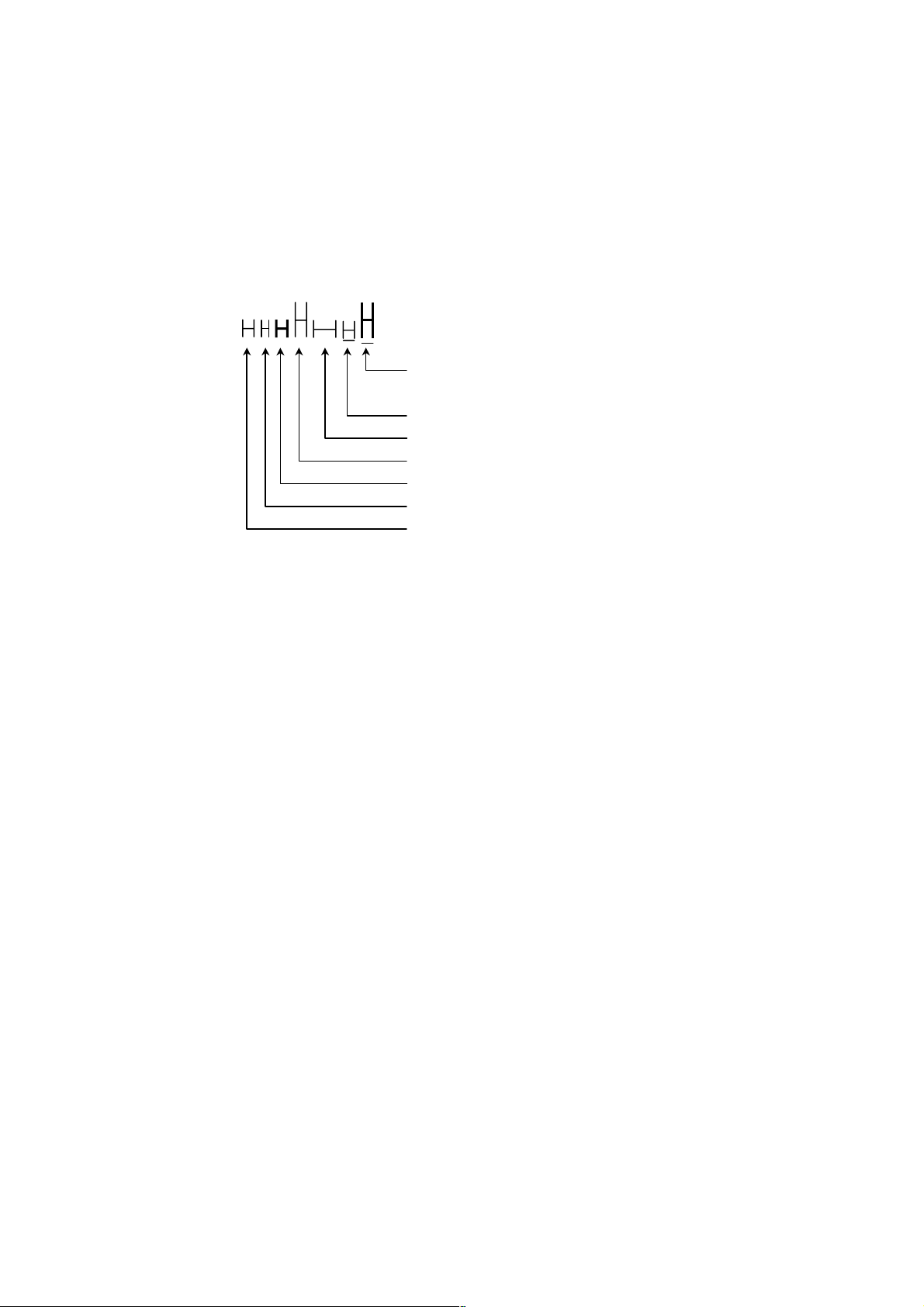
LPRINT CHR$(&H1B);"!";CHR$(&H00);"H";
LPRINT CHR$(&H1B);"!";CHR$(&H01);"H";
LPRINT CHR$(&H1B);"!";CHR$(&H08);"H";
LPRINT CHR$(&H1B);"!";CHR$(&H10);"H";
LPRINT CHR$(&H1B);"!";CHR$(&H20);"H";
LPRINT CHR$(&H1B);"!";CHR$(&H80);"H";
LPRINT CHR$(&H1B);"!";CHR$(&HB9);"H";
LPRINT CHR$(&HA);
Font B + Emphasis + Quadruple + Underline
Font A + Underline
Font A + Double width
Font A + Double height
Font A + Emphasis
Font B
Font A
— 15 —
ESC % n
[Function] Specifying/canceling download character set
[Code] <1B>H<25>H<n>
[Range] 0 n 255
[Outline] Specifying/canceling download characters.
•“n” is valid only for the lowest bit (n0).
• Control by the lowest bit (n0) is shown as follows:
n0 Function
0 Canceling download character set
1 Specifying download character set
[Default] n = 0
[See Also] ESC &
[Sample Program]
[Print Results]
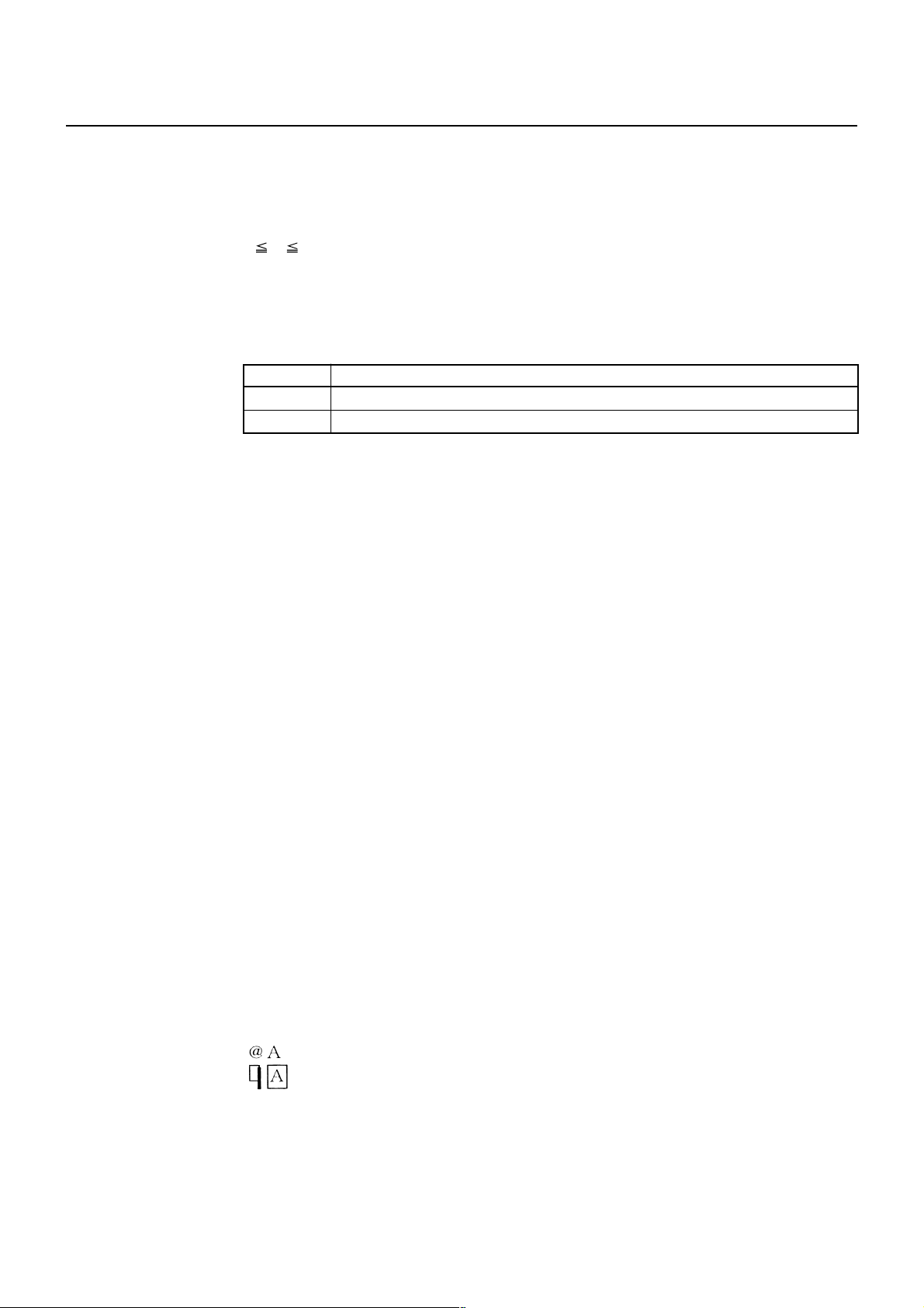
GOSUB SETCHR DATA 6
LPRINT CHR$(&H1B);"%";CHR$(0); DATA &HFF,&H80,&H00
LPRINT "@A";CHR$(&HA); DATA &H80,&H80,&H00
LPRINT CHR$(&H1B);"%";CHR$(1); DATA &H80,&H80,&H00
LPRINT "@A";CHR$(&HA); DATA &H80,&H80,&H00
END DATA &HFF,&HFF,&HFF
SETCHR: DATA &HFF,&HFF,&HFF
LPRINT CHR$(&H1B);"&"; DATA 12
LPRINT CHR$(3);"@";"A"; DATA &HFF,&HFF,&HFF
FOR J=1 TO 2 DATA &H80,&H07,&HF9
READ REP DATA &H80,&HFF,&HF9
LPRINT CHR$(REP); DATA &H87,&HFE,&H01
FOR I=1 TO REP*3 DATA &H9F,&H06,&H01
READ D DATA &HF8,&H06,&H01
LPRINT CHR$(D); DATA &HF8,&H06,&H01
NEXT I DATA &H9F,&H06,&H01
NEXT J DATA &H87,&HFE,&H01
RETURN DATA &H80,&HFF,&HF9
DATA &H80,&H07,&HF9
DATA &HFF,&HFF,&HFF
← Internal character set
← Download character
— 16 —
ESC & s n m [a [p] s × a] m–n+1
[Function] Defining the download characters
[Code] <1B>H<26>H<s>H<n>H<m>H[<a>H<p1>H<p2>··<ps × a>]m – n + 1
[Range] s = 3 (Font A, B)
s = 2 (Font C)
32 n m 126
0 a 12 (Font A)
0 a 9 (Font B)
0 a 8 (Font C)
0 p1 ⋅ ⋅ ps × a 255
[Outline] Defines the font of download characters of alphanumeric characters.
•“s” indicates the number of bytes in vertical direction.
•“n” indicates the start character code and “m” the end character code. To define
only one character, set n = m.
• Character codes definable includes 95 ASCII codes in total in the range of <20>H to
<7E>H.
•“a” indicates the number of dots to be defined in horizontal direction.
•“p” is the data to be defined, which indicate a pattern equal to “a” dots in horizontal
direction from the left end. The rest of the pattern on the right side is filled with
space.
• The number of data to be defined is “s × a”.
• Download characters thus defined remain valid until redefinition, execution of ESC
@, GS *, FS q, GS (A, deletion by ESC ?, or power OFF is performed.
[Caution] • Download characters and download bit images cannot be defined simultaneously.
• Running this command clears the definition of the download bit image.
[Default] Same as the internal character set.
[See Also] ESC %, ESC ?
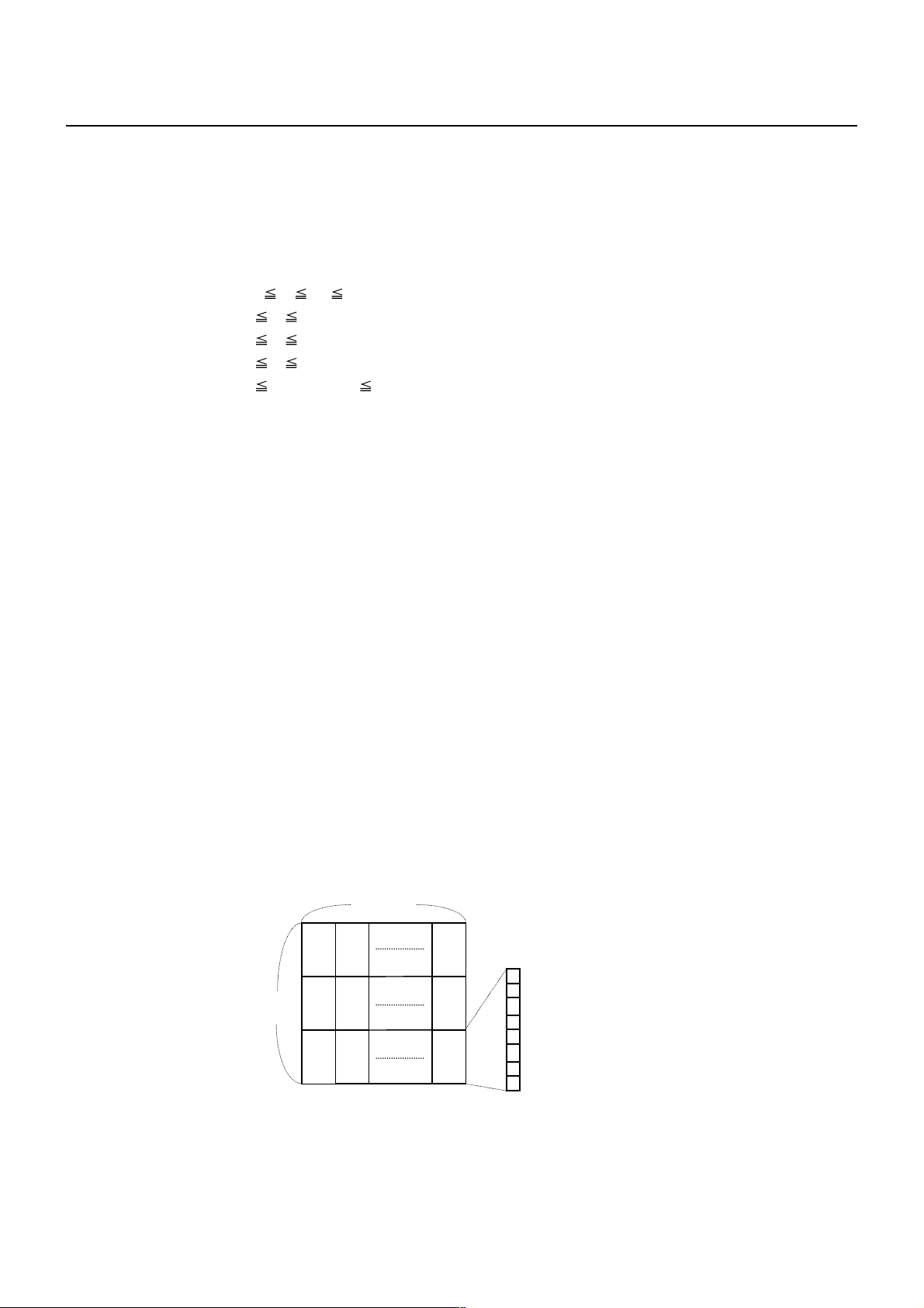
[Example]
p1
24 dots
Create each data bit by setting “1” for a printed dot and “0” for an unprinted dot.
p2
p3
12 dots
p4
p5
p6 p36
Font A
p34
MSB
p35
LSB
[Sample Program] Refer to Sample Program and Print Results for ESC %.
— 17 —
ESC – n
[Function] Specifying/canceling underline
[Code] <1B>H<2D>H<n>
[Range] 0 n 2
48 n 50
[Outline] Specifying/canceling an underline.
n Function
0, 48 Canceling underline
1, 49 Setting 1-dot width underline
2, 50 Setting 2-dot width underline
[Caution] • An underline is attached to the full character width. It is, however, not attached to
the part having been skipped by horizontal tab (HT) command.
• An underline is not attached to 90°-right-turned characters and white-on-black
character.
• Underline can also be specified/canceled by ESC ! but the setting of command last
processed is valid.
• Specifying/canceling by this command is not valid for kanji.
• Underline width is constant in the specified thickness regardless of the character
size.
[Default] n = 0
[See Also] ESC !, FS –
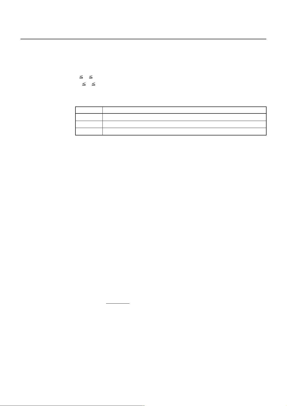
[Sample Program]
LPRINT CHR$(&H1B);"-";CHR$(0);
LPRINT "AAAAA";
LPRINT CHR$(&H1B);"-";CHR$(1);
LPRINT "AAAAA";CHR$(&HA);
[Print Results]
Underline canceled
←→
AAAAAAAAAA
←→
Underline specified
— 18 —

ESC ? n
[Function] Deleting download characters
[Code] <1B>H<3F>H<n>
[Range] 32 n 126
[Outline] Deletes the downloaded characters of specified code.
[Caution] • The character “n” indicates the character code used to delete the defined pattern.
After the deletion, characters are printed in the same pattern as the internal
characters.
• This command deletes the code-defined pattern of the character font selected by
ESC !.
• This command is ignored if the specified character code is undefined.
[See Also] ESC &, ESC %
— 19 —

ESC E n
[Function] Specifying/canceling emphasis printing
[Code] <1B>H<45>H<n>
[Range] 0 n 255
[Outline] Specifying/canceling the emphasized characters.
•“n” is valid only for the lowest bit (n0).
• Control by the lowest bit (n0) is shown as follows:
n0 Function
0 Canceling emphasis printing
1 Specifying emphasis printing
[Caution] • Emphasis printing can also be specified/canceled by ESC ! but the setting of
command last processed is valid.
• Valid for all character types except HRI characters.
[Default] n = 0
[See Also] ESC !
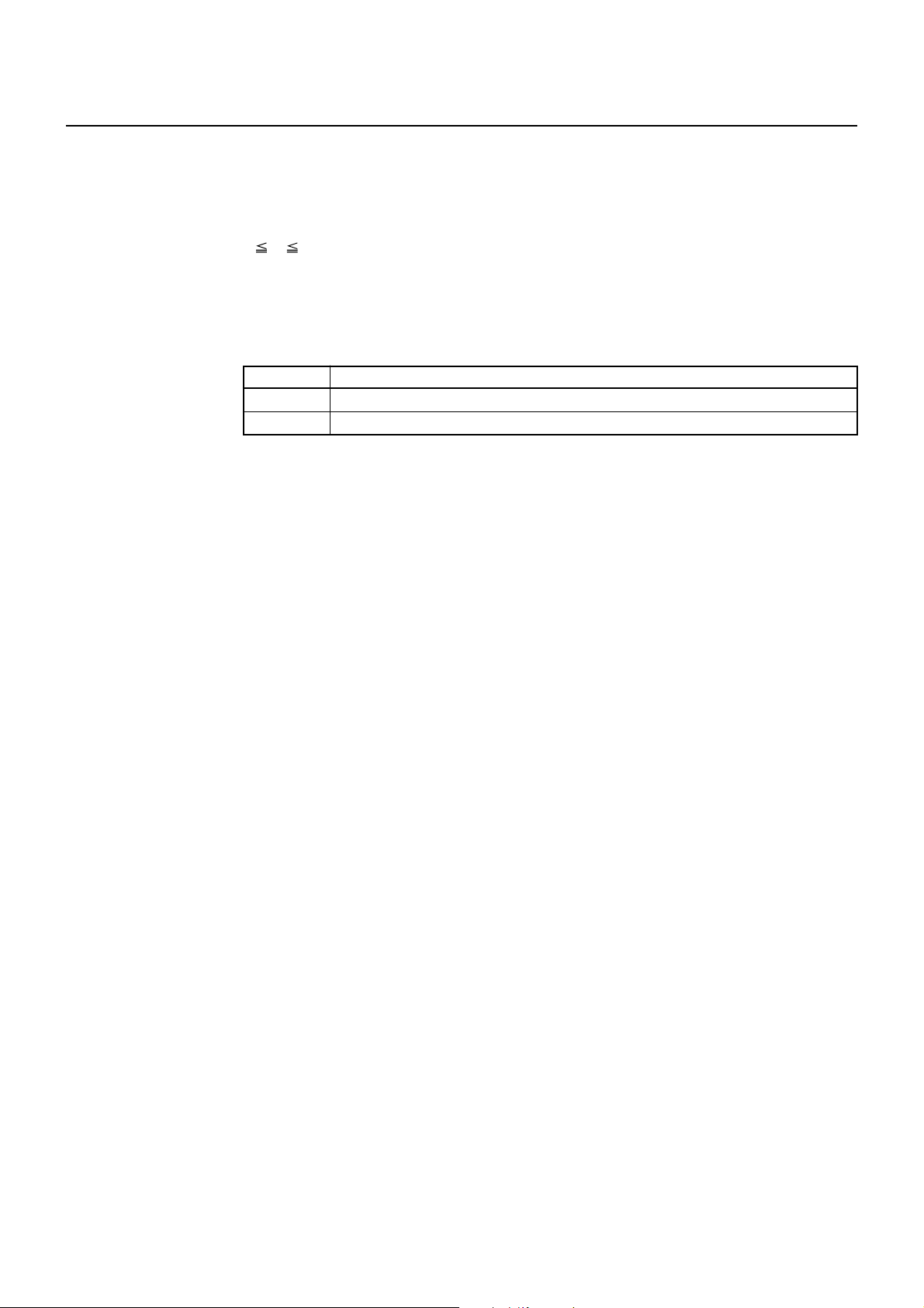
[Sample Program]
LPRINT CHR$(&H1B);"E";CHR$(0);
LPRINT "AAABBB";CHR$(&HA);
LPRINT CHR$(&H1B);"E";CHR$(1);
LPRINT "AAABBB";CHR$(&HA);
[Print Results]
AAABBB ← Emphasis canceled
AAABBB ← Emphasis specified
— 20 —
ESC G n
[Function] Specifying/canceling double strike printing
[Code] <1B>H<47>H<n>
[Range] 0 n 255
[Outline] Specifying/canceling the double strike printing.
•“n” is valid only for the lowest bit (n0).
• Control by the lowest bit (n0) is shown as follows:
n0 Function
0 Canceling double strike printing
1 Specifying double strike printing
[Caution] • With this printer, double-strike printing and emphasis printing provide completely
the same results.
• Valid for all character types except HRI characters.
[Default] n = 0
[See Also] ESC E
[Sample Program]
LPRINT CHR$(&H1B);"G";CHR$(0);
LPRINT "AAABBB";CHR$(&HA);
LPRINT CHR$(&H1B);"G";CHR$(1);
LPRINT "AAABBB";CHR$(&HA);
[Print Results]
AAABBB ← Double strike printing canceled
AAABBB ← Double strike printing specified
— 21 —
ESC M n
[Function] Selection of character fonts
[Code] <1B>H<4D>H<n>
[Range] 0 n 2
48 n 50
[Outline] Selects character fonts.
n Function
0, 48 Selection of font A (12 × 24)
1, 49 Selection of font B (9 × 24)
2, 50 Selection of font C (8 × 16)
[Caution] • ESC ! can also select fonts, but the setting made by the command that has last
been processed becomes valid.
• In case font C selection ESC R is other than n = 8 (katakana), codepage PC437 is
printed.
• In case ESC R is n = 8 (katakana), codepage katakana is printed.
[Default] n = 0
[See Also] ESC !
ESC R n
[Function] Selecting the international character set
[Code] <1B>H<52>H<n>
[Range] 0 n 13
[Outline] Depending on the value of “n”, one of the following character sets is specified;
n Character Set n Character Set
0 U.S.A. 7 Spain I
1 France 8 Japan
2 Germany 9 Norway
3 U.K. 10 Denmark II
4 Denmark I 11 Spain II
5 Sweden 12 Latin America
6 Italy 13 Korea
[Default] n = 0 (Overseas), n = 8 (Domestic)
[See Also] 3.2 “International Character Code Table”
— 22 —
ESC V n
[Function] Specifying/canceling 90°-right-turned characters
[Code] <1B>H<56>H<n>
[Range] 0 n 2
48 n 50
[Outline] Specifying/canceling 90°-right-turned characters.
n Function
0, 48 Canceling 90°-right-turned characters
1, 49 Specifying 90°-right-turned characters
[Caution] • No underlines are attached to 90°-right-turned characters.
• This command does not affect PAGE MODE but setting is maintained.
[Default] n = 0
[Sample Program]
LPRINT CHR$(&H1B);"V";CHR$(0);
LPRINT "AAAAA";
LPRINT CHR$(&H1B);"V";CHR$(1);
LPRINT "AAAAA";CHR$(&HA);
[Print Results]
90° rotation canceled
←→
AAAAA
90° rotation specified
A
A
A
A
A
←→
— 23 —
ESC t n
[Function] Selecting the character code table
[Code] <1B>H<74>H<n>
[Range] 0 n 9
16 n 19
n = 22, 255
[Outline] Selecting the character code table.
The character code table is selected based on the value of “n”.
n Character Code Table
0 Codepage PC437
1 Katakana
2 Codepage PC850
3 Codepage PC860
4 Codepage PC863
5 Codepage PC865
6, 18 Codepage PC852
7, 17 Codepage PC866
8 Codepage PC857
9, 16 WPC1252
19 Codepage PC858
26 Thai code 18
40 Codepage PC864
255 Space Page (For user setting)
[Default] This is a character code table specified with the value of “n”.
[Sample Program]
LPRINT CHR$(&H1B);"t";CHR$(0);
LPRINT "n=0 ";
LPRINT CHR$(C);
FOR C=&HB1 TO &HB5
NEXT C
LPRINT CHR$(&HA);
LPRINT CHR$(&H1B);"t";CHR$(1);
LPRINT "n=1 ";
FOR C=&HB1 TO &HB5
LPRINT CHR$(C);
NEXT C
LPRINT CHR$(&HA);
[Print Results]
n = 0
n= 9
← n = 0
← n = 9
— 24 —
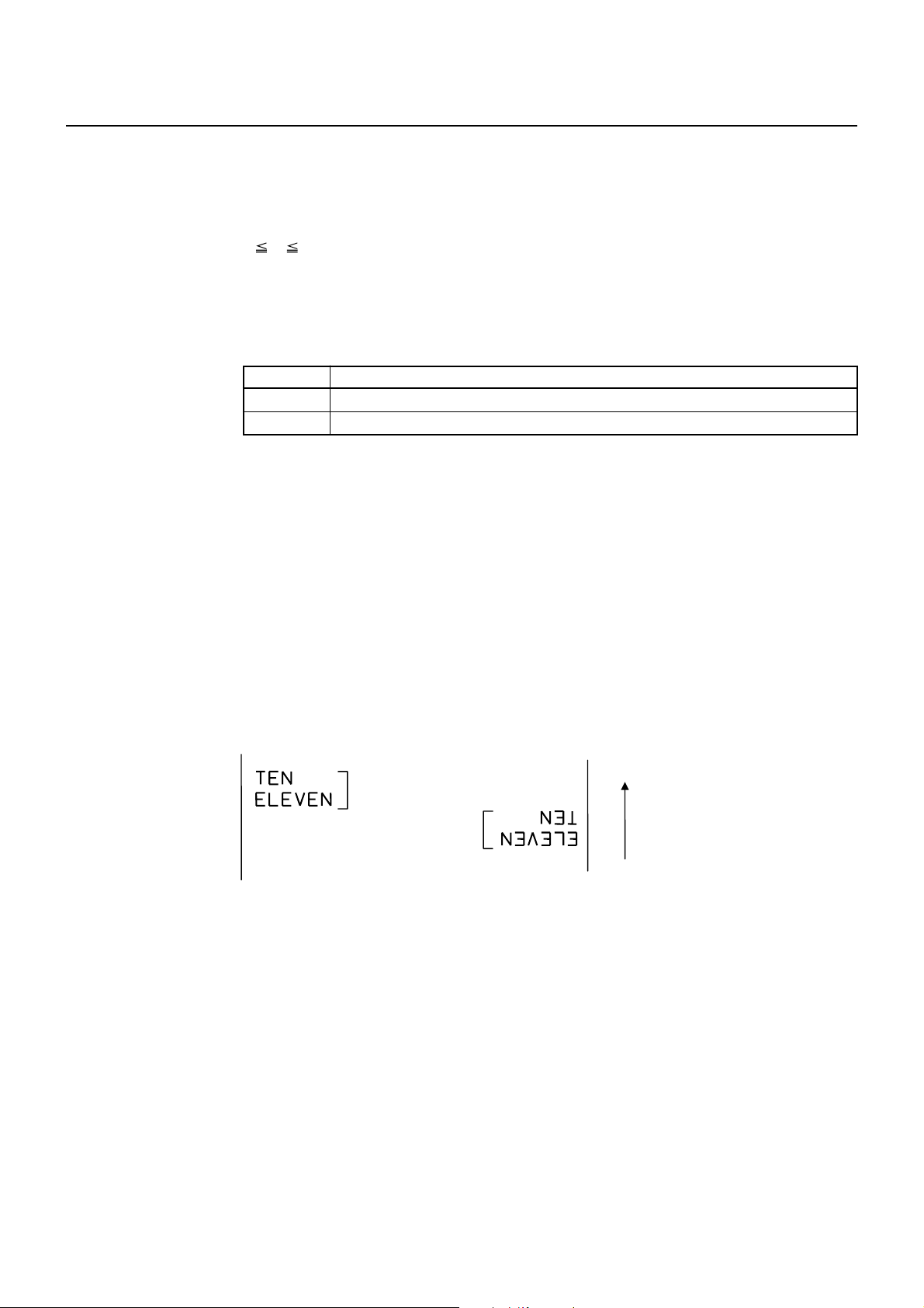
ESC { n
[Function] Specifying/canceling the inverted characters
[Code] <1B>H<7B>H<n>
[Range] 0 n 255
[Outline] Specifying/canceling inverted characters.
•“n” is valid only for the lowest bit (n0).
• Control by the lowest bit (n0) is shown as follows:
n0 Condition
0 Canceling inverted characters.
1 Specifying inverted characters.
[Caution] • This command is valid only when it is specified at the beginning of a line.
• This command does not affect the PAGE MODE.
[Default] n = 0
[Sample Program]
[Print Results]
LLPRINT CHR$(&H1B);"{";CHR$(0);
LPRINT "TEN";CHR$(&HA);
LPRINT "ELEVEN";CHR$(&HA);
LPRINT CHR$(&H1B);"{";CHR$(1);
LPRINT "TEN";CHR$(&HA);
LPRINT "ELEVEN";CHR$(&HA);
Inversion canceled
Inversion specified
Paper feed direction
— 25 —

ESC ~ J n (Valid in CBM1000II-Compatible Mode)
[Function] Specifies/cancels printing in red (black-based paper)
[Code] <1B>H<7E>H<4A>H<n>
[Range] 0 n 255
[Outline] Specifies or cancels printing in red.
• Red printing is valid on black-based thermal paper. Specifies or cancels printing in
black on red-based thermal paper.
•“n” is valid only for the lowest bit (n0).
• Control by the lowest bit (n0) is shown as follows:
n0
0 Cancels red printing Cancels black printing
1 Specifies red printing Specifies black printing
[Caution] • Valid when 2-color paper is specified by the ESC ( E command.
• Valid only when dedicated thermal paper is used.
• This command must not be used for normal thermal paper.
• Conducting pulse amount after cancellation is standard value. At the time of setting,
conducting pulse amount is increased to change the coloring.
[Default] n = 0
[Sample Program]
LPRINT CHR$(&H1B);"~";"J";CHR$(1);
LPRINT "AAAAA";CHR$(&HA);
LPRINT CHR$(&H1B);"~";"J";CHR$(0);
LPRINT "AAAAA";CHR$(&HA);
[Print Results]
AAAAA ← Red printing
AAAAA ← Black printing
Black-based Paper Red-based Paper
Function
* When dedicated thermal paper (black-based paper) is used.
— 26 —

DC3 n (Valid in CBM1000II-Compatible Mode)
[Function] Specifies/cancels printing in red (black-based paper)
[Code] <13>H<n>
[Range] 0 n 255
[Outline] Specifies or cancels printing in red.
• Red printing is valid on black-based thermal paper. Specifies or cancels printing in
black on red-based thermal paper.
•“n” is valid only for the lowest bit (n0).
• Control by the lowest bit (n0) is shown as follows:
n0
0 Cancels red printing Cancels black printing
1 Specifies red printing Specifies black printing
[Caution] • Valid when 2-color paper is specified by the ESC ( E command.
• Valid only at the top of a line.
• Valid only when dedicated thermal paper is used.
• This command must not be used for normal thermal paper.
• Conducting pulse amount after cancellation is standard value. At the time of setting,
conducting pulse amount is increased to change the coloring.
[Default] n = 0
[Sample Program]
LPRINT CHR$(&H1B);"~";"J";CHR$(1);
LPRINT "AAAAA";CHR$(&HA);
LPRINT CHR$(&H1B);"~";"J";CHR$(0);
LPRINT "AAAAA";CHR$(&HA);
[Print Results]
AAAAA ← Red printing
AAAAA ← Black printing
Black-based Paper Red-based Paper
Function
* When dedicated thermal paper (black-based paper) is used.
— 27 —

GS ! n
[Function] Specifying the character size
[Code] <1D>H<21>H<n>
[Range] 0 n 255, where:
1 vertical magnification 8, 1 horizontal magnification 8
[Outline] Specifies the character size (Vertical and horizontal magnification).
Bit Function
0
1
2
3
4
5
6
7
Table 1 Horizontal Magnification
Hex. Decimal Magnification
00 0 1 × (Standard)
10 16 2 × (Double width)
20 32 3 ×
30 48 4 ×
40 64 5 ×
50 80 6 ×
60 96 7 ×
70 112 8 ×
Vertical magnification
specification
Horizontal magnification
specification
Value
Hex. Number Decimal Number
Refer to Table 2, “Vertical
Magnification”.
Refer to Table 1, “Horizontal
Magnification”.
Table 2 Vertical Magnification
Hex. Decimal Magnification
00 0 1 × (Standard)
01 1 2 × (Double )
02 2 3 ×
03 3 4 ×
04 4 5 ×
05 5 6 ×
06 6 7 ×
07 7 8 ×
[Caution] • This command is valid for all characters (alphanumeric, kana, and kanji) except for
HRI characters.
• This command is ignored if either the vertical magnification or horizontal
magnification is out of the defined range.
• In STANDARD MODE, the vertical direction is defined as the paper feed direction,
and the horizontal direction is defined as the direction perpendicular to the paper
feed.
• Setting memory SW 3-7 to ON allows the horizontal and vertical relations to be
interchanged when 90°-right-turnning of character is specified.
• In PAGE MODE, the vertical direction means the top-bottom direction of each
character. The horizontal direction means the side-to-side direction of each
character. If characters of different vertical magnification are contained in a line,
the baseline of each character is lined up.
• Horizontal and vertical magnification can also be specified/canceled by ESC ! but
the setting of command last processed is valid.
[Default] n = 0
[See Also] ESC !
— 28 —

GS B n
[Function] Specifying/canceling the black/white inverted printing
[Code] <1D>H<42>H<n>
[Range] 0 n 255
[Outline] This command specifies or cancels the black/white inverted printing.
•“n” is valid only for the lowest bit (n0).
• Control by the lowest bit (n0) is shown as follows:
n0 Function
0 The black/white inverted printing is canceled.
1 The black/white inverted printing is specified.
[Caution] • The black/white inversion works on internal and downloaded characters.
• The black/white inversion works also on the right spacing of characters defined by
ESC SP.
• This command does not affect the bit image, downloaded bit image, bar code, HRI
characters, or the skip area specified by HT, ESC $, or ESC \.
• This command does not affect the space between lines.
• Black/white inversion specification takes precedence over underline specification.
Underline printing specified is, therefore, nullified if black/white inversion is
specified; the underline setting, however, remains unchanged.
[Default] n = 0
— 29 —

GS b n
[Function] Specifying/canceling the smoothing
[Code] <1D>H<62>H<n>
[Range] 0 n 255
[Outline] This command specifies or cancels the smoothing.
•“n” is valid only for the lowest bit (n0).
• Control by the lowest bit (n0) is shown as follows:
n0 Function
0 The smoothing is canceled.
1 The smoothing is specified.
[Caution] • Smoothing is effective to printer’s internal characters, download characters, and
non-standard characters.
• Smoothing is not effective to characters with either of their vertical or horizontal
magnification is ×1.
[Default] n = 0
[See Also] ESC !, GS !
— 30 —

2.2.3 Print Position Commands
HT
[Function] Horizontal tab
[Code] <09>H
[Outline] Shifts the printing position to the next horizontal tab position.
• Ignored when the next horizontal tab position has not been set.
[Caution] The horizontal tab position is set by ESC D.
[Default] At the selection of font A, tabs are set every 8 characters (at 9th, 17th, 25th, ...) with
right space amount of a character set at 0 and horizontal enlargement rate of a
character set at 1.
[See Also] ESC D
[Sample Program]
LPRINT "012345678901234567890";CHR$(&HA);
LPRINT CHR$(&H9);"AAA";
LPRINT CHR$(&H9);"BBB";CHR$(&HA);
LPRINT CHR$(&H1B);"D";
LPRINT CHR$(3);CHR$(7);CHR$(14);CHR$(0);
LPRINT CHR$(&H9);"AAA";
LPRINT CHR$(&H9);"BBB";
LPRINT CHR$(&H9);"CCC";CHR$(&HA);
[Printing Result]
12345678901234567890
AAA BBB ← Initially set horizontal tab
AAA BBB CCC ← When set to the 4th, 8th, and 15th columns
— 31 —

ESC $ n1 n2
[Function] Specifying the absolute positions
[Code] <1B>H<24>H<n1><n2>
[Range] 0 n1 255
0 n2 255
[Outline] The printing start position is specified by the absolute position from the left margin
with the number of dots divided by 256 and quatient specified as “n2” and remainder
as “n1”.
Therefore, the printing start position is designated as n1 + n2 × 256 × basic calculation
pitch from the left margin.
[Caution] • The basic calculation pitch is set by GS P. After the line feed width is set, if the
basic calculation by GS P leaves a fraction, the fraction is corrected with the
minimum pitch of the mechanism, and the remainder is omitted.
• In STANDARD MODE, this command uses the horizontal (Paper feed direction) basic
calculation pitch (x).
• In PAGE MODE, this command acts differently depending on the start point:
(1) If the start point specified by ESC T is top right or bottom left, the command
uses the vertical (Paper feed direction) basic calculation pitch (y).
(2) If the start point specified by ESC T is top left or bottom right , the command
uses the horizontal (Perpendicular to the paper feed direction) basic calculation
pitch (x). Specification beyond the end of the line is ignored.
[See Also] ESC \, GS P, GS \, GS $
[Sample Program]
LPRINT CHR$(&H1B);"$";
LPRINT CHR$(0);CHR$(0);"A";
LPRINT CHR$(&H1B);"$";
LPRINT CHR$(50);CHR$(0);"B";
LPRINT CHR$(&H1B);"$";
LPRINT CHR$(0);CHR$(1);"C";CHR$(&HA);
LPRINT CHR$(&H1B);"$";
LPRINT CHR$(100);CHR$(0);"A";
LPRINT CHR$(&H1B);"\";
LPRINT CHR$(&HC2);CHR$(&HFF);"B";CHR$(&HA);
[Print Results]
Absolute position specified
050
A
100
B
BA
256
C
Relative position specified
–62
— 32 —

ESC D [ n ] k NULL
[Function] Setting horizontal tab position
[Code] <1B>H<44>H [<n>] k<00>H
[Range] 1 n 255
0 k 32
[Outline] Specifying a horizontal tab position.
•“n” indicates the number of columns from the beginning to the horizontal tab
position. Note, however, that “n = set position – 1”. For example, to set the position
at 9th column, n = 8 is to be specified.
•“k” denotes the number of horizontal tab positions you want to set.
• The tab position is set at a position where it is “character width × n” from the
beginning of a line. The character width, at this time, includes the space on the
right. In double width characters, it is made double the ordinary case.
• Tab positions that can be specified are maximum 32. Specifying tab positions
exceeding this limit is ignored.
• <n> k, which denotes a setting position, is input in the increasing order and ends at
<00> H.
• ESC D <NULL> clears all the set tab positions. Following clearing, the horizontal
tab command is ignored.
[Caution] • When the data, <n> k, is equal to or smaller than its preceding data, <n> k-1, it is
assumed that tab setting is finished. If this is the case, the next data onward will be
processed as normal data.
• When the data, <n> k, exceeds a 1-line print area, set the horizontal tab position, as
“Set column position = Maximum print columns + 1”.
• The horizontal tab position does not change even if the character width is altered
after setting the horizontal tab position.
[Default] • At the selection of font A, tabs are set every 8 characters (at 9th, 17th, 25th, ...) with
right space amount of a character set at 0 and horizontal enlargement rate of a
character set at 1.
[See Also] HT
[Sample Program] Refer to Sample Program and Print Results for HT.
— 33 —

ESC T n
[Function] Selecting the character printing direction in PAGE MODE
[Code] <1B>H<54>H<n>
[Range] 0 n 3
48 n 51
[Outline] Selects the direction and start point of character printing in PAGE MODE.
n Printing Direction Start Point
0, 48 Left to right Top left (“A” in the figure)
1, 49 Bottom to top Bottom left (“B” in the figure)
2, 50 Right to left Bottom right (“C” in the figure)
3, 51 Top to bottom Top right (“D” in the figure)
A
[Caution] • When STANDARD MODE is selected, this command only executes the internal
flagging of the printer without affecting the printing in STANDARD MODE.
• The character mapping position will be the start point of the print area specified by
ESC W.
• The basic calculation pitch (x or y) used by the following commands varies with the
start point.
(1) If the start point is the top left or bottom right (The characters are mapped in
the direction perpendicular to the paper feed),
• Commands using x: ESC SP, ESC S, ESC \
• Commands using y: ESC 3, ESC J, GS $, GS \
(2) If the start point is the top right or bottom left (The characters are mapped in
the paper feed direction),
• Commands using x: ESC 3, ESC J, GS $, GS \
• Commands using y: ESC SP, ESC S, ESC \
D
Paper feed direction
[Default] n = 0
[See Also] Appendix 4.1 “Explanation on PAGE MODE”
ESC $, ESC L, ESC W, ESC \, GS $, GS P, GS \
— 34 —

ESC W xL xH yL yH dxL dxH dyL dyH
[Function] Defining the print area in PAGE MODE
[Code] <1B>H<57>H<xL><xH><yL><yH><dxL><dxH><dyL><dyH>
[Range] 0 xL, xH, yL, yH, dxL, dxH, dyL, dyH 255,
except for dxL = dxH = 0 or dyL = dyH = 0
[Outline] Defines the location and size of the print area.
• Horizontal start point = [(xL + xH × 256) × basic calculation pitch] inches
• Vertical start point = [(yL + yH × 256) × basic calculation pitch] inches
• Horizontal length = [(dxL + dxH × 256) × basic calculation pitch] inches
• Vertical length = [(dyL + dyH × 256) × basic calculation pitch] inches
[Caution] • When STANDARD MODE is selected, this command only executes the internal
flagging of the printer without affecting the printing in STANDARD MODE.
• If the horizontal start point or vertical start point is out of the printable area, this
command is canceled and the next data is handled as normal data.
• If the horizontal length or vertical length is 0, this command is canceled and the
next data is handled as normal data.
• The character mapping position will be the start point specified by ESC T in the
print area.
• If the “horizontal start point + horizontal length” is greater than the horizontal
printable area, the “horizontal printable area – horizontal start point” is taken as
the horizontal length.
• If the “vertical start point + vertical length” is greater than the vertical printable
area, the “vertical printable area – vertical start point” is taken as the vertical length.
• The basic calculation pitch is defined by GS P. Once defined, the print area is not
changed if the basic calculation pitch is changed by GS P.
• Fractions resulting from calculations are corrected with the minimum pitch of the
mechanism, and the remainder is omitted.
• The horizontal start point and horizontal length are calculated with the basic
calculation pitch (x). The vertical start point and vertical length are calculated with
the basic calculation pitch (y).
• The figure below illustrates the print area, where X = horizontal start point, Y =
vertical start point, Dx = horizontal length, and Dy = vertical length.
Paper
Print Area
The printable area for this printer is approximately 72.070 mm (576/203 inches)
horizontally and 117 mm (938/203 inches) vertically.
[Default] xL = xH = yL = yH = 0
When paper width is 80 mm: dxL = 64, dxH = 2, dyL = 126, dyH = 6
When paper width is 58 mm: dxL = 128, dxH = 1, dyL = 126, dyH = 6
[See Also] Appendix 4.1 “Explanation on PAGE MODE”
CAN, ESC L, ESC T, GS P
— 35 —
<
Paper feed direction

ESC \ nL nH
[Function] Specifying the relative position
[Code] <1B>H<5C>H<nL><nH>
[Range] 0 nL 255
0 nH 255
[Outline] This command specifies the next print start position in a relative position with respect
to the current position. The next print start position will be at a point of [(nL + nH ×
256) × basic calculation pitch] inches away from the current position.
[Caution] • Specification of a position outside the print area is ignored.
• If a new position is specified to the right of the current position in the direction of
printing, it should be specified as positive (+). If it is to the left, it should be as
negative (–).
• A negative value is the complement of 65536. For example, to move the position
by N pitches to the left, specify it as:
nL + nH × 256 = 65536 – N
• The basic calculation pitch is set by GS P.
• Fractions resulting from calculation are corrected with the minimum pitch of the
mechanism, and the remainder is omitted.
• In STANDARD MODE, this command uses the horizontal basic calculation pitch (x).
• In PAGE MODE, this command acts differently depending on the start point:
(1) If the start point specified by ESC T is top left or bottom right, the command
specifies the relative position in the direction perpendicular to the paper feed
(The character’s side-to-side direction), using the horizontal basic calculation
pitch (x).
(2) If the start point is top right or bottom left, the command specifies the relative
position in the paper feed direction (The character’s side-to-side direction), using
the vertical basic calculation pitch (y).
[See Also] ESC $, GS P
[Sample Program] Refer to Sample Program and Print Results for ESC $.
— 36 —
ESC a n
[Function] Aligning the characters
[Code] <1B>H<61>H<n>
[Range] 0 n 2
48 n 50
[Outline] All the printed data within one line are aligned in the specified position.
Depending on the value “n”, positional alignment is carried out as shown in the
table below:
n Position
0, 48 Left end alignment
1, 49 Centering
2, 50 Right end alignment
[Caution] • This command is valid only when it is inputted at the beginning of a line.
• This command does not affect the PAGE MODE.
• Executes justification in the print area being set.
[Default] n = 0
[Sample Program]
LPRINT CHR$(&H1B);"a";CHR$(0);
LPRINT "AAAAA";CHR$(&HA);
LPRINT CHR$(&H1B);"a";CHR$(1);
LPRINT "AAAAA";CHR$(&HA);
LPRINT CHR$(&H1B);"a";CHR$(2);
LPRINT "AAAAA";CHR$(&HA);
[Print Results]
AAAAA
Left-justified Centered Right-justified
AAAAA
AAAAA
<
Paper feed direction
— 37 —

GS $ nL nH
[Function] Specifying the absolute position of character vertical direction in PAGE MODE
[Code] <1D>H<24>H<nL><nH>
[Range] 0 nL 255, 0 nH 255
[Outline] Specifies the vertical position of character at the start point of data development in
PAGE MODE using absolute position based on the start position. The position of
vertical direction of character at the start position of next data development is the
position [(nL + nH × 256) × basic calculation pitch] from the start position.
[Caution] • This command is ignored except at PAGE MODE selection.
• Absolute position setting exceeding the specified print area is ignored.
• Position in horizontal direction of character at the start position of data development
is not shifted.
• Start point used as the reference is set by <ESC T>.
• The following operation occurs at the start point of <ESC T>.
(1) When start point is set at “upper left” or “lower right”, the absolute position of
paper feed direction (vertical direction of character) is set. In this case, basic
calculation pitch (y) of vertical direction is used.
(2) When start point is set at “upper right” or “lower left”, the absolute position of
vertical direction of paper feed (vertical direction of character) is set. In this
case, basic calculation pitch (x) of horizontal direction is used.
• Basic calculation pitch is set by <GS P>.
• When fractional number is caused by the calculation, it is corrected by the minimum
pitch of mechanism and the rest is discarded.
[See Also] ESC $, ESC T, ESC W, ESC \, GS P, GS \
— 38 —
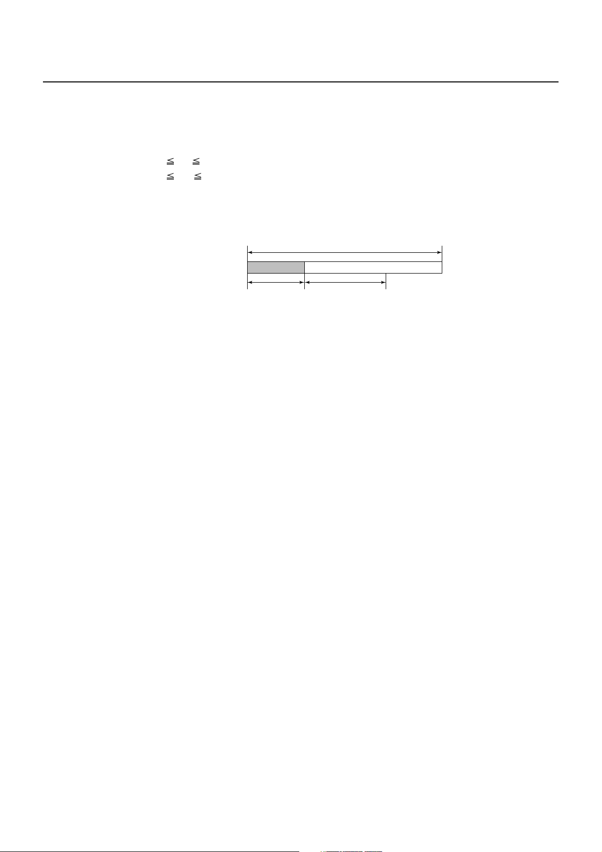
GS L nL nH
[Function] Setting the left margin
[Code] <1D>H<4C>H<nL><nH>
[Range] 0 nL 255
0 nH 255
[Outline] This command sets the left margin specified by nL and nH.
The value of the left margin is [(nL + nH × 256) × basic calculation pitch] inches.
Printable area
Left
margin
[Caution] • This command only works when it is entered at the beginning of a line.
• When PAGE MODE is selected, this command only executes the internal flagging
of the printer.
• The setting of this command does not affect PAGE MODE.
• The maximum settable left margin is equal to the horizontal printable area. A
setting greater than this maximum is trimmed to the maximum.
• The basic calculation pitch is defined by GS P. Once defined, the left margin is not
changed if the basic calculation pitch is changed by GS P.
• The left margin is calculated with the horizontal basic calculation pitch (x) set by
GS P. A fraction resulting from the calculation is corrected with the minimum pitch
of the mechanism, and the remainder is omitted.
• When mapping character data, if the print area specified is not wide enough to
accommodate one character of the current font, only the line for that character
data is handled as follows:
(1) The print area is extended toward the right to be equivalent to one character of
the current font, but not wider than the printable area.
(2) If an area for one character cannot be provided as a result of step (1), the print
area is extended toward the left. (So, the left margin is decreased.)
• When mapping non-character data (bit image, downloaded bit image, or bar code),
if the print area specified is narrower than 9-bits, only the line for that data is handled
as follows:
(1) The print area is extended toward the left (so, the left margin is decreased)
until it is 9-dot wide, but not wider than the printable area.
Print area
width
[Default] nL = 0, nH = 0
[See Also] GS P, GS W
— 39 —

GS W nL nH
[Function] Setting the print area width
[Code] <1D>H<57>H<nL><nH>
[Range] 0 nL 255
0 nH 255
[Outline] Sets the print area width specified by nL and nH.
The print area width will be [(nL + nH × 256) × basic calculation pitch] inches.
Printable area
Left
margin
[Caution] • This command only works when it is entered at the beginning of a line.
• When PAGE MODE is selected, this command only executes the internal flagging
of the printer.
• The setting of this command does not affect PAGE MODE.
• If the value entered with this command exceeds the printable area for one line, the
entire area except the left margin is set as the print area width.
• The basic calculation pitches are defined by GS P. Once defined, the print area
width is not changed if the basic calculation pitch is changed by GS P.
• The print area width is calculated with the horizontal basic calculation pitch (x)
defined by GS P. A fraction resulting from the calculation is corrected with the
minimum pitch of the mechanism, and the remainder is omitted.
• If the first character to be mapped at the beginning of a line has a width (including
the right spacing) greater than the print area width, only that line is handled as
follows:
(1) The print area is extended toward the right to accommodate the first character,
but not wider than the printable area.
Left margin
Print area width
Print area
width
Printable area
A
(1) Extended toward the right
— 40 —

(2) If a sufficient area cannot be provided as a result of step (1), the print area is
extended toward the left (so, the left margin is decreased).
Printable area
Left margin
(2) The left margin
is trimmed
(3) If a sufficient area cannot be provided as a result of step (2), the right spacing is
trimmed.
• When mapping a bit image (or downloaded bit image), if the print area is narrower
than the minimum width of the bit image (two dots for single density, or one dot
for double density), only the line for that image is handled as follows:
(1) The print area is extended toward the left (so, the left margin is decreased)
until it is equal to the minimum width of the image, but not wider than the
printable area.
[Default] When paper width is 80 mm: nL = 64, nH = 2
When paper width is 58 mm: nL = 128, nH = 1
[See Also] GS L, GS P
A
(1) Extended
toward the right
Print area width
— 41 —

GS \ nL nH
[Function] Specifying the relative vertical position of a character in PAGE MODE
[Code] <1D>H<5C>H<nL><nH>
[Range] 0 nL 255
0 nH 255
[Outline] This command is used in PAGE MODE to specify the vertical position of a character
in the data mapping start position, in a relative position with respect to the current
position. The next data mapping start position will be at a point [(nL + nH × 256) ×
basic calculation pitch] inches away from the current position.
[Caution] • This command is ignored when PAGE MODE is not selected.
• If a new position is specified for a character located beneath the current position, it
should be specified as positive (+). If it is above the current position, it should be
negative (–).
• A negative value is the complement of 65536. For example, to move the position
by N pitches up, specify it as:
nL + nH × 256 = 65536 – N
• The specification of a relative position outside the specified print area is ignored.
• Depending on the start point specified by ESC T, this command acts as follows:
(1) If the start point is the top left or bottom right, the command specifies the
relative position in the paper feed direction (the character’s top-bottom direction)
using the vertical basic calculation pitch (y).
(2) If the start point is the top right or bottom left, the command specifies the
relative position in the direction perpendicular to the paper feed (the character’s
top-bottom direction) using the horizontal basic calculation pitch (x).
• The basic calculation pitch is set by GS P.
• Fractions resulting from calculations are corrected with the minimum pitch of the
mechanism, and the remainder is omitted.
— 42 —

2.2.4 Line Feed Span Commands
ESC 2
[Function] Specifying 1/6-inch line feed rate
[Code] <1B>H<32>H
[Outline] The line feed rate per line is specified by 1/6 inch.
[Caution] Line feed rate can be specified respectively for both STANDARD MODE and PAGE
MODE.
[Sample Program]
LPRINT "AAAAA";CHR$(&HA);
LPRINT CHR$(&H1B);"3";CHR$(0);
LPRINT "AAAAA";CHR$(&HA);
LPRINT CHR$(&H1B);"3";CHR$(50);
LPRINT "AAAAA";CHR$(&HA);
LPRINT CHR$(&H1B);"2";
LPRINT "AAAAA";CHR$(&HA);
LPRINT "AAAAA";
LPRINT CHR$(&H1B);"J";CHR$(100);
LPRINT "AAAAA";CHR$(&HA);
LPRINT "AAAAA";CHR$(&HA);
[Print Results]
AAAAA
AAAAA
AAAAA
AAAAA
AAAAA
AAAAA
AAAAA
1/6-inch line feed
0/360-inch line feed
50/360-inch line feed
1/6-inch line feed
100 /360-inch line feed
1/6-inch line feed
— 43 —

ESC 3 n
[Function] Setting line feed rate of minimum pitch
[Code] <1B>H<33>H<n>
[Range] 0 n 255
[Outline] Sets the line feed width per line to [n × basic calculation pitch] inches.
[Χαυτιον] • The line feed width can be set separately for the STANDARD and PAGE MODES.
• The basic calculation pitch is set by GS P. Once defined, the line feed width is not
changed if the basic calculation pitch is changed by GS P.
• Fractions resulting from calculation are corrected with the minimum pitch of the
mechanism, and the remainder is omitted.
• In STANDARD MODE, this command uses the vertical (paper feed direction) basic
calculation pitch (y).
• In PAGE MODE, this command acts differently depending on the start point:
(1) If the start point specified by ESC T is top left or bottom right, the command
uses the vertical (paper feed direction) basic calculation pitch (y).
(2) If the start point specified by ESC T is top right or bottom left, the command
uses the horizontal (perpendicular to the paper feed direction) basic calculation
pitch (x).
• The maximum settable line feed width is 1016 mm (40 inches). A setting greater
than this maximum is trimmed to the maximum.
[Default] Approx. 4.23 mm
[See Also] ESC 2, GS P
— 44 —

2.2.5 Bit Image Commands
ESC * m n1 n2 [ d ] k
[Function] Specifying the bit image mode
[Code] <1B>H<2A>H<m>H<n1><n2>[<d>]k
[Range] m = 0, 1, 32, 33
0 n1 255
0 n2 2
0 d 255
k = n1 + 256 × n2 (m = 0, 1)
k = (n1 + 256 × n2) × 3 (m = 32, 33)
[Outline] • According to the number of dots specified in “n1”, “n2”, specify the bit image of
mode “m”.
• The number of dots printed is divided by 256, whose quotient is taken as n2 and
residual as “n1”. The total number of dots printed in the horizontal direction is
equal to n1 + (256 × n2).
• When bit image data have been input in excess of dot positions that can be printed
on one line, the excess data are discarded.
•”d” is bit image data. Bits to be printed are specified as “1” and those not as “0”.
• The bit image modes specified by “m” are shown as follows:
Vertical Direction Horizontal Direction
m Mode No. Dot Dot Max. No.
of Dots Density Density of Dots
0 8-dots single density 8 67 DPI 101 DPI 288
1 8-dots double density 8 67 DPI 203 DPI 576
32 24-dots single density 24 203 DPI 101 DPI 288
33 24-dots double density 24 203 DPI 203 DPI 576
[Caution] • When the value of “m” is out of the above range, the data following after “n1” is
processed as normal printing data.
• After completion of bit image printing, the printer returns to normal data processing
mode.
— 45 —

[Sample Program]
LPRINT CHR$(&H1B);"*";
LPRINT CHR$(0);CHR$(20);CHR$(0); IMG1:
GOSUB IMG1 LPRINT CHR$(&HFF);
LPRINT CHR$(&HA); FOR I = 1 TO 18
LPRINT CHR$(&H1B);"*"; LPRINT CHR$(&H85);
LPRINT CHR$(1);CHR$(20);CHR$(0); NEXT I
GOSUB IMG1 LPRINT CHR$(&HFF);
LPRINT CHR$(&HA); RETURN
LPRINT CHR$(&H1B);"*"; IMG2:
LPRINT CHR$(32);CHR$(20);CHR$(0); LPRINT CHR$(&HFF);
GOSUB IMG2 LPRINT CHR$(&HFF);
LPRINT CHR$(&HA); LPRINT CHR$(&HFF);
LPRINT CHR$(&H1B);"*"; FOR I = 1 TO 18
LPRINT CHR$(33);CHR$(20);CHR$(0); LPRINT CHR$(&H80);
GOSUB IMG2 LPRINT CHR$(&H00);
LPRINT CHR$(&HA); LPRINT CHR$(&H05);
END NEXT I
LPRINT CHR$(&HFF);
LPRINT CHR$(&HFF);
LPRINT CHR$(&HFF);
RETURN
[Print Results]
← 8-dots single density
← 8-dots double density
← 24-dots single density
← 24-dots double density
— 46 —

GS * n1 n2 [ d ] n1 × n2 × 8
[Function] Defining the download bit image
[Code] <1D>H<2A>H<n1><n2> [< d >] n1 × n2 × 8
[Range] 1 n1 255
1 n2 48
n1 × n2 1536
[Outline] • Defines download bit images of the number of dots specified by “n1” and “n2”.
• The numbers of dots are n1 × 8 in horizontal direction and n2 × 8 in vertical direction.
•”d” indicates bit image data.
• Once defined, the download bit image remains effective until it is redefined, ESC
@, ESC &, GS (A, or FS q, is executed, or power is turned OFF.
[Caution] • Relations between the bit image data and the dots defined are shown below.
• With this command executed, the defined content of a downloaded character is
cleared.
[See Also] GS /
n2 × 8 dots
d1
d2
dn2
dn2 + 1
dn2 + 2
dn2 × 2
n1 × 8 dots
MSB
dn2 × 2 + 1
dn2 × 2 + 2
LSB
dn2 × n2 × 8
— 47 —
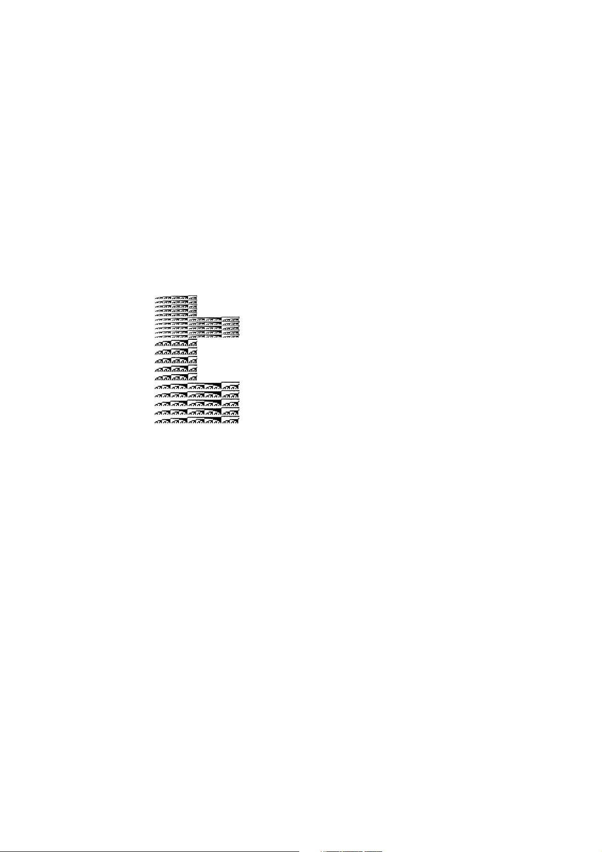
[Sample Program]
[Print Results]
GOSUB IMG
LPRINT CHR$(&H1D);"/";CHR$(0);
LPRINT CHR$(&H1D);"/";CHR$(1);
LPRINT CHR$(&H1D);"/";CHR$(2);
LPRINT CHR$(&H1D);"/";CHR$(3);
END
IMG:
n1=10:n2=5
LPRINT CHR$(&H1D);"*";
LPRINT CHR$(n1);CHR$(n2);
FOR J=1 TO n1*8
FOR I=1 TO n2
LPRINT CHR$(J);
NEXT I
NEXT J
RETURN
— 48 —

GS / m
[Function] Printing the downloaded bit image
[Code] <1D>H<2F>H<m>
[Range] 0 m 3
48 m 51
[Outline] Prints downloaded bit image in a mode specified by “m”.
Modes that can be selected by “m” are shown below.
m Mode Name
0, 48 NORMAL MODE 203 DPI 203 DPI
1, 49 DOUBLE WIDTH MODE 203 DPI 101 DPI
2, 50 DOUBLE HEIGHT MODE 101 DPI 203 DPI
3, 51 QUADRUPLE SIZE MODE 101 DPI 101 DPI
[Caution] • When a downloaded bit image has not been defined, this command is ignored.
• When data exist in the print buffer, this command is ignored.
• A portion of a downloaded bit image exceeding one line length is not printed.
[See Also] ESC &, GS *
Dot Density in Dot Density in
Vertical Direction Horizontal Direction
— 49 —

GS v 0 m xL xH yL yH d1...dk
[Function] Printing of raster bit image
[Code] <1D>H<76>H<30>H<m><xL><xH><yL><yH> [<d>] k
[Range] 0 m 3, 48 m 51, 0 xL 255, 0 xH 255,
0 yL 255, 0 yH 8, 0 d 255,
k = (xL + xH × 256) × (yL + yH × 256), however, k ≠ 0
[Outline] Prints raster bit images in mode “m”.
m Mode Name
0, 48 NORMAL MODE 203 DPI 203 DPI
1, 49 DOUBLE WIDTH MODE 203 DPI 101 DPI
2, 50 DOUBLE HEIGHT MODE 101 DPI 203 DPI
3, 51 QUADRUPLE SIZE MODE 101 DPI 101 DPI
• xL, xH specify the number of data in horizontal direction of the bit image to (xL +
xH × 256) bytes.
• yL, yH specify the number of data in vertical direction of the bit image to (yL + yH ×
256) bytes.
[Caution] • In STANDARD MODE, this command is valid only when there is no print data in the
print buffer.
• Any of the print modes (character size, emphasis, double strike, inverting,
underlining, back-to-white reversing, etc.) does not affect the raster bit image.
• If the print area specified by GS L and GS W is narrower than a minimum width,
the print area for that line only is extended to the minimum width. The minimum
width is one dot in NORMAL MODE (m = 0, 48) and DOUBLE HEIGHT MODE (m = 2,
50), and 2 dots in DOUBLE WIDTH MODE (m = 1, 49) and QUADRUPLE SIZE MODE
(m = 3, 51).
• Any part of data that is out of the print area is only read and discarded in units of
dot.
• The print start position can arbitrarily be specified with HT (horizontal tab), ESC $
(specifying absolute position), ESC \ (specifying relative positions), and GS L (setting
left margins). Note that if the print start position is not a multiple of 8, the printing
speed may decrease.
• The setting of ESC a (aligning characters) are also valid for the raster bit image.
• If this command is executed during macro definition, the macro definition is
suspended, and the processing of the command starts. The macro is left undefined.
•“d” denotes defined data. Dots to be printed are specified as “1”, and those not to
be printed as “0”.
Dot Density in Dot Density in
Vertical Direction Horizontal Direction
— 50 —

[Example] When xL + xH × 256 = 64
(xL + xH × 256) × 8 dots = 512 dots
123 62
65 66 67
7
6 5 4 3 2 1 0
MSB
LSB
126
K-2
63 64
127
K-1
128
yL + yH × 256 dots
K
— 51 —

2.2.6 Status Commands
DLE EOT n
[Function] Sending status in real-time
[Code] <10>H<04>H<n>
[Range] 1 n 4
[Outline] Sends in real-time the status specified by “n”.
n Status
1 Printer status
2 Status caused by an offline condition
3 Status caused by an error
4 Continuous paper detector status
[Caution] • Each status represents the current status. It is 1 byte data.
• The status is transferred without checking whether the host is ready to receive or
busy.
• This command is executed even if the printer is in offline state, receive-buffer full
state, or error state.
• This command is dealt with when it is received.
• With serial interface specifications, this command is executed in offline state,
receiving buffer full state, and error state.
• With parallel interface specifications, this command cannot be executed while the
printer is in Busy state.
When memory SW1-3 is ON, the printer does not enter Busy state in the offline
state and error state.
• If ASB (Automatic Status Back) is enabled by GS a, it is necessary to discriminate
between the status due to ASB and the status due to this command.
• This command can be executed even if printer setting by ESC = is invalid.
• If another data string of <10>H<04>H<n> (1 n 4) is received, the printer acts the
same way as with this command. Therefore, the user should be reminded of this
fact.
[Example 1]
Suppose a command “ESC * m nL nH [d1 ... dk]”, where d1 = <10>H, d2 = <04>H,
d3 = <01>H.
The DLE EOT n command cannot be interleaved into the code string of another
command consisting of 2 bytes or more.
[Example 2]
If the printer sends DLE EOT 3 after the host has sent up to ESC 3 in its attempt to
send ESC 3 n, the printer handles the ESC 3 as ESC 3 <10>H. Thus, the user should
be cautious.
— 52 —

(1) Printer status (When n = 1 is specified)
Bit Status Hex. Decimal
0 Fixed 00 0
1 Fixed 02 2
Status of pin 3 of drawer kick-out connector = L 00 0
2
Status of pin 3 of drawer kick-out connector = H 04 4
Online status 00 0
3
Offline status 08 8
4 Fixed 10 16
Not waiting online recovery 00 0
5
Waiting online recovery 20 32
FEED switch is not pressed 00 0
6
FEED switch is pressed 40 64
7 Fixed 00 0
(2) Status caused by an offline condition (When n = 2 is specified)
Bit Status Hex. Decimal
0 Unused 00 0
1 Unused 02 2
Cover closed 00 0
2
Cover open 04 4
Not in paper feed state triggered by FEED switch 00 0
3
In paper feed state triggered by FEED switch 08 8
4 Unused 10 16
Printing is not stopped because of “paper out”
5 state
00 0
Printing is stopped because of “paper out” state 20 32
Error not occurred 00 0
6
Error occurred 40 64
7 Unused 00 0
Bit 5: Printing is stopped if the Paper-end detector detects a “paper out” state,
or if the printer is out of paper when the Paper Near-end Sensor is enabled
by ESC c 4. At this time, bit 5 = 1.
— 53 —

(3) Status caused by an error (when n = 3 is specified)
Bit Status Hex. Decimal
0 Fixed 00 0
1 Fixed 02 2
No B.M detection error occurred
(only when B.M paper is selected)
2
A B.M detection error occurred
(only when B.M paper is selected)
Auto cutter error not occurred 00 0
3
00 0
04 4
Auto cutter error occurred 08 8
4 Fixed 10 16
Unrecoverable error not occurred 00 0
5
Unrecoverable error occurred 20 32
6 Auto recovery error not occurred 00 0
Auto recovery error occurred 40 64
7 Fixed 00 0
Bit 3: If this error occurred because of a paper jam, for example, remove the
cause of the error, and then DLE ENQ n (1 n 2) can be used to recover
from the error. However, it is not possible to recover from any error due
to a circuit problem (e.g., broken wire).
Bit 6: If a head overheat error is detected, the printing is stopped until the head
temperature falls. At this time, bit 6 = 1.
(4) Continuous paper detector status (When n = 4 is specified)
Bit Status Hex. Decimal
0 Fixed 00 0
1 Fixed 02 02
Paper found by Paper Near-end Sensor 00 0
2
Paper not found by Paper Near-end Sensor 04 4
Paper found by Paper Near-end Sensor 00 0
3
Paper not found by Paper Near-end Sensor 08 8
4 Fixed 10 16
Paper found by Paper-end Sensor 00 0
5
Paper not found by Paper-end Sensor 60 96
Paper found by Paper-end Sensor 00 0
6
Paper not found by Paper-end Sensor 40 64
7 Fixed 00 0
[See Also] Appendix 4.3 “Identification of Send Status”
DLE ENQ, ESC c 4, GS a, GS r
— 54 —

GS a n
[Function] Enabling/disabling ASB (Automatic Status Back)
[Code] <1D>H<61>H<n>
[Range] 0 n 255
[Outline] This command selects the status item to be addressed by ASB (Automatic Status
Back.)
Bit Status Item Addressed by ASB Hex. Decimal
Status of pin 3 of drawer kick-out connector =
Disabled
0
Status of pin 3 of drawer kick-out connector =
Enabled
Online/offline status = Disabled 00 0
1
Online/offline status = Enabled 02 2
Error status = Disabled 00 0
2
Error status = Enabled 04 4
Continuous Paper Sensor = Disabled 00 0
3
Continuous Paper Sensor = Enabled 08 8
4 Undefined ——
5 Undefined ——
6 Undefined ——
7 Undefined ——
00 0
01 1
[Caution] • If any status item is enabled, the status is sent to the host when this command is
executed. After that time on, the status is sent each time an enabled status item
changes. Because each status item represents the current condition, status items
disabled for ASB may also have changed.
• The ASB function is disabled if all status items are disabled.
• If the ASB function is enabled by default, the host receives the status the first time
the printer gets ready for communication after it is turned on.
• The printer sends 4 bytes of status shown in the tables below, without checking
whether the host is ready to receive or busy. The 4 bytes of status is a continuous
string except for XOFF code.
• Because this command is executed when data is mapped in the receive buffer,
there may be a delay between command receiving and status sending depending
on the condition of the receive buffer.
• Even if the printer is excluded from the selection of peripheral equipment ESC =,
the 4 bytes of status is sent to the host whenever status changes.
• When DLE EOT, GS I, or GS r is used, the host must discriminate between the
status specified by these commands and the status due to ASB.
— 55 —
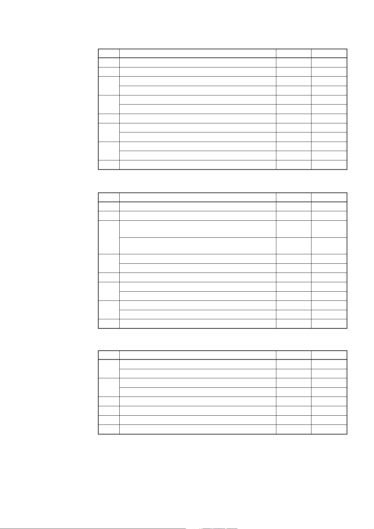
(1) 1st byte (Printer information)
Bit Status Hex. Decimal
0 Unused 00 0
1 Unused 00 0
Status of pin 3 of drawer kick-out connector = “L” 00 0
2
Status of pin 3 of drawer kick-out connector = “H” 04 4
Online status 00 0
3
Offline status 08 8
4 Unused 01 16
Cover closed 00 0
5
Cover open 20 32
Not in paper feed state triggered by FEED switch 00 0
6
In paper feed state triggered by FEED switch 40 64
7 Unused 00 0
(2) 2nd byte (Error occurrence information)
Bit Status Hex. Decimal
0 Undefined ——
1 Undefined ——
No B.M detection error occurred
(only when B.M paper is selected).
2
A B.M detection error occurred
(only when B.M paper is selected).
Auto cutter error not occurred 00 0
3
00 0
04 4
Auto cutter error occurred 08 8
4 Unused 00 0
Unrecoverable error not occurred 00 0
5
Unrecoverable error occurred 20 32
Auto recovery error not occurred 00 0
6
Auto recovery error occurred 40 64
7 Unused 00 0
(3) 3rd byte (Paper Sensor information)
Bit Status Hex. Decimal
Paper found by Paper Near-end Sensor 00 0
0, 1
Paper not found by Paper Near-end Sensor 03 3
Paper found by Paper-end Sensor 00 0
2, 3
Paper not found by Paper-end Sensor 0C 12
4 Unused 00 0
5 Undefined ——
6 Undefined ——
7 Unused 00 0
— 56 —

(4) 4th byte (Paper Sensor information)
Bit Status Hex. Decimal
0 Undefined ——
1 Undefined ——
2 Undefined ——
3 Undefined ——
4 Unused 00 0
5 Undefined ——
6 Undefined ——
7 Unused 00 0
* In case of MSW3-7 ON (CBM1000 compatible mode)
(4) 4th byte (Paper Sensor information)
Bit Status Hex. Decimal
0 Reserved 01 1
1 Reserved 02 2
2 Reserved 04 4
3 Reserved 08 8
4 Fixed 00 0
5 Reserved 00 00
6 Reserved 00 00
7 Fixed 00 0
* In case of MSW3-7 OFF (CBM1000 non-compatible mode)
[Default] When MSW 1-3 OFF: n = 0
When MSW 1-3 ON: n = 2
[See Also] DLE EOT, GS r
— 57 —

GS r n
[Function] Sending status
[Code] <1D>H<72>H<n>
[Range] 1 n 2
49 n 50
[Outline] Sends the specified status to the host.
n Function
1, 49 Sends the Paper Sensor status.
2, 50 Sends the Drawer Kick-out Connector status.
[Caution] • When the serial interface is used:
For DTR/DSR control:
The printer sends the status after verifying that the host is ready to receive. If the
host is not ready to receive, the printer waits for the host to become ready to
receive.
For XON/XOFF control:
The printer sends the status without checking whether the host is ready to receive
or busy.
• Because this command is executed when data is mapped in the receive buffer,
there may be a delay between receiving the command and sending the status
depending on the condition of the receive buffer.
• If ASB (Automatic Status Back) is enabled by GS a, the host must discriminate
between the status due to this command and the status due to ASB.
• Paper Sensor status (n = 1, 49)
Bit Status Hex. Decimal
Paper found by Paper Near-end Sensor 00 0
0, 1
Paper not found by Paper Near-end Sensor 03 3
Paper found by Paper-end Sensor 00 0
2, 3
Paper not found by Paper-end Sensor (0C) (12)
4 Unused 00 0
5 Undefined ——
6 Undefined ——
7 Unused 00 0
Bits 2, 3: Whenever the Paper-end Sensor detects a “paper out” state, the printer
goes offline, and the command is not executed. Therefore, the printer
never sends a status “No paper in Paper-end detector (0CH)”.
— 58 —

• Drawer kick-out connector status (n = 2, 50)
Bit Status Hex. Decimal
Status of pin 3 of drawer kick connector = “L” 00 0
0
Status of pin 3 of drawer kick connector = “H” 01 1
1 Undefined ——
2 Undefined ——
3 Undefined ——
4 Unused 00 0
5 Undefined ——
6 Undefined ——
7 Unused 00 0
[See Also] Appendix 4.3 “Identification of Send Status”
DLE EOT, GS a
— 59 —

2.2.7 Paper Detecting Commands
ESC c 3 n
[Function] Selecting the Paper Sensor valid for a Paper-end signal output
[Code] <1B>H<63>H<33>H<n>
[Range] 0 n 255
[Outline] This command selects by which Paper Sensor a Paper-end signal should be output.
Each bit for “n” has the following meaning:
Bit Position
0 Paper Near-end Disabled Enabled
1 Paper Near-end Disabled Enabled
2 Paper-end Disabled Enabled
3 Paper-end Disabled Enabled
4 Undefined — —
5 Undefined — —
6 Undefined — —
7 Undefined — —
[Caution] This command is valid only for the parallel interface.
[Default] n = 15
Value
01
— 60 —

ESC c 4 n
[Function] Selecting the Paper Near-end Sensor valid for print stop
[Code] <1B>H<63>H<34>H<n>
[Range] 0 n 255
[Outline] This command selects the Paper Near-end Sensor which helps to stop printing when
the paper supply almost runs out.
Each bit for “n” has the following meaning:
Bit Position
0 Paper Near-end Disabled Enabled
1 Paper Near-end Disabled Enabled
2 Undefined — —
3 Undefined — —
4 Undefined — —
5 Undefined — —
6 Undefined — —
7 Undefined — —
[Caution] This printer can only select one kind of Paper Sensor, a Paper Near-end Sensor.
[Default] n = 0
01
Value
— 61 —

2.2.8 Panel Switch Commands
ESC c 5 n
[Function] Enabling/disabling the panel switches
[Code] <1B>H<63>H<35>H<n>
[Range] 0 n 255
[Outline] Enabling/disabling the FEED switch.
• “n” is valid only for the lowest bit (n0).
• Control by the lowest bit (n0) is shown as follows:
n0 Condition
0 FEED switch valid
1 FEED switch invalid
[Caution] • When the FEED switch is disabled with this command, the paper cannot be fed by
operating the FEED switch.
• While switch operation is waited at the execution of macro, the FEED switch is
always enabled regardless of the setting of this command but no paper feed
operation is carried out.
[Default] n = 0
[Sample Program]
LPRINT CHR$(&H1B);"c5";CHR$(0); ← When enabling the FEED switch
LPRINT CHR$(&H1B);"c5";CHR$(1); ← When disabling the FEED switch
— 62 —

2.2.9 Macro Commands
GS :
[Function] Starting/ending macro definition
[Code] <1D>H<3A>H
[Outline] Specifying starting/ending macro definition.
Reception of this command during macro definition signifies ending the macro
definition.
[Caution] • Maximum content available for macro definition is 2048 bytes. A portion exceeding
2048 bytes is not defined.
• When GS ^ is processed in macro definition, the macro definition is stopped and
the content of definition is cleared.
• Even with ESC @ (Initialization of the printer) having been executed, defined content
is not cleared. Therefore, it is possible to include ESC @ into the content of macro
definition.
• Normal printing operation is carried out even during macro definition.
[Default] The initial value is not defined.
[See Also] GS ^
[Sample Program]
LPRINT CHR$(&H1D);":";
LPRINT "+------+";CHR$(&HA);
LPRINT "| |";CHR$(&HA);
LPRINT "+------+";CHR$(&HA);
LPRINT CHR$(&H1D);":";
LPRINT CHR$(&H1D);"^";
LPRINT CHR$(2);CHR$(10);
[Print Results]
<
Normal printing during macro definition
<
<
Printing during macro execution
<
— 63 —

GS ^ n1 n2 n3
[Function] Executing the macro
[Code] <1D>H<5E>H<n1><n2><n3>
[Range] 0 n1 255
0 n2 255
0 n3 1
[Outline] Executing contents defined in macro.
n1 : The number of times of macro execution
n2 : Waiting time on macro execution: Waiting time of n2 × 100 msec is given for
every execution.
n3 : Macro execution mode
n3 = 0 Continuous execution: The Macro is executed “n1” times continuously at the
time interval specified by “n2”.
n3 = 1 Execution by FEED Switch: After waiting for the time specified by “n2”, the
ARARM LED flickers and the FEED switch is waiting to be pressed. When it is pressed,
the macro is executed once. This action is repeated “n1” times.
[Caution] • When this command is received while in macro definition, suspension of macro
definition is indicated. At this time, the defined content is cleared.
• No execution takes place when the macro is held undefined.
• While in macro execution with n3 = 1, paper feed with the FEED switch is not
available.
[See Also] GS :
[Sample Program] Refer to Sample Program and Print Results for GS:.
— 64 —

2.2.10 Cutter Commands
GS V m ......... (1)
GS V m n ..... (2)
[Function] Cutting the paper
[Code] (1) <1D>H<56>H<m>
(2) <1D>H<56>H<m><n>
[Range] (1) m = 1, m = 49
(2) m = 66
[Outline] Performs the specified paper cutting.
m Function
0, 48 Full cut
1, 49 Partial cut (Leaving a bridge area uncut)
65 Paper feed by “cut position + {n × basic calculation pitch}” and partial cut
66 Paper feed by “cut position + {n × basic calculation pitch}” and partial cut
[Caution] • In STANDARD MODE, this command only works when it is entered at the beginning
of a line.
• Control to make the length of cut paper less than 10 mm is not excecuted.
For (1):
• Executes cutting of paper.
For (2):
• If n = 0, the paper is fed to the cut position, and then cut. If n ≠ 0, the paper is fed by
“n × basic calculation pitch” inches past the cut position, and then cut.
• The basic calculation pitch is set by GS P.
The paper feed amount is calculated with the vertical basic calculation pitch (y).
A fraction resulting from the calculation is corrected with the minimum pitch of the
mechanism, and the remainder is omitted.
— 65 —

2.2.11 Bar Code Commands
GS H n
[Function] Selecting of printing position of HRI characters
[Code] <1D>H<48>H<n>
[Range] 0 n 3
48 n 51
[Outline] Selecting printing position of HRI characters in printing bar codes.
“n” means the followings.
n Printing Position
0, 48 No printing
1, 49 Above the bar code
2, 50 Below the bar code
3, 51 Both above and below the bar code
The HRI characters refer to the bar code-turned characters so that you can read them.
[Caution] • The HRI characters are printed in the font selected with GS f.
• Specify before the GS k command.
[Default] n = 0
[See Also] GS f, GS k
[Sample Program]
LPRINT CHR$(&H1B);”3”;CHR$(5);
LPRINT CHR$(&H1D);”h”;CHR$(50);
LPRINT CHR$(&H1D);”H”;CHR$(0);
GOSUB BC
LPRINT CHR$(&H1D);”H”;CHR$(1);
GOSUB BC
LPRINT CHR$(&H1D);”H”;CHR$(2);
GOSUB BC
LPRINT CHR$(&H1D);”H”;CHR$(3);
GOSUB BC
END
BC:
LPRINT CHR$(&H1D);”k”;
LPRINT CHR$(4);
LPRINT “12”;CHR$(0);
LPRINT CHR$(&HA);
RETURN
— 66 —

[Print Results]
No HRI characters
Printed above
Printed below
Printed above and below
— 67 —

GS f n
[Function] Selecting the font of HRI characters
[Code] <1D>H<66>H<n>
[Range] n = 0, 1
[Outline] Selecting the font of HRI characters in printing bar code.
The type of font can be selected with “n” as follows:
n Font
0, 48 Font A (12 × 24)
1, 49 Font B (9 × 24)
2, 50 Font C (8 × 16)
The HRI characters refer to the bar code-turned characters so that you can read them.
[Caution] The HRI characters are printed at the position specified with GS H.
[Default] n = 0
[See Also] GS H
[Sample Program]
LPRINT CHR$(&H1D);"h";CHR$(50);
LPRINT CHR$(&H1D);"H";CHR$(2);
LPRINT CHR$(&H1D);"f";CHR$(0);
GOSUB BC
LPRINT CHR$(&H1D);"f";CHR$(1);
GOSUB BC
END
BC:
LPRINT CHR$(&H1D);"k";
LPRINT CHR$(4);
LPRINT “12”;+CHR$(0);
LPRINT CHR$(&HA);
RETURN
[Print Results]
← FONT A
← FONT B
— 68 —

GS h n
[Function] Specifying the height of the bar code
[Code] <1D>H<68>H<n>
[Range] 1 n 255
[Outline] Selecting bar code height.
“n” denotes the number of dots in the vertical direction.
[Default] n = 162
[See Also] GS k, GS w
[Sample Program] Refer to Sample Program and Print Results for GS w.
— 69 —

GS k m [d1 ...... dk] NULL ......... (1)
GS k m n [d1 ...... dn] ................ (2)
[Function] Printing the bar code
[Code] (1) <1D>H<6B>H<m> [d1.....dk] NULL
(2) <1D>H<6B>H<m><n> [d1....dn]
[Range] (1) 0 m 6 The definitions of “k” and “d” vary with the bar code system.
(2) 65 m 73 The definitions of “n” and “d” vary with the bar code system.
[Outline] Selects a bar code system and prints the bar code.
For (1):
m Bar Code System Range of “k” Range of “d”
0 UPC-A 11 k 12 48 d 57
1 UPC-E 11 k 12 48 d 57
2 JAN13 (EAN) 12 k 13 48 d 57
3 JAN8 (EAN) 7 k 8 48 d 57
4 CODE39 1 k
5 ITF 1 k (An even number) 48 d 57
6 CODABAR 1 k
48 d 57, 65 d 90
32, 36, 37, 43, 45, 46, 47
48 d 57, 65 d 68
36, 43, 45, 46, 47, 58
For (2):
m Bar Code System Range of “n” Range of “d”
65 UPC-A 11 n 12 48 d 57
66 UPC-E 11 n 12 48 d 57
67 JAN13 (EAN) 12 n 13 48 d 57
68 JAN8 (EAN) 7 n 8 48 d 57
69 CODE39 1 n 255
70 ITF
71 CODABAR 1 n 255
72 CODE93 1 n 255 0 d 127
73 CODE128 2 n 255 0 d 127
1 n 255 (An even
number)
48 d 57, 65 d 90
32, 36, 37, 43, 45, 46, 47
48 d 57
48 d 57, 65 d 68
36, 43, 45, 46, 47, 58
— 70 —

[Caution] For (1):
• This command ends with a NULL code.
• For UPC-A or UPC-E, the bar code is printed when 12 bytes of bar code data have
been entered, and the subsequent data is handled as normal data.
• For JAN13, the bar code is printed when 13 bytes of bar code data have been
entered, and the subsequent data is handled as normal data.
• For JAN8, the bar code is printed when 8 bytes of bar code data have been entered,
and the subsequent data is handled as normal data.
• The data of ITF bar code must have an even number of columns. Should the data
have an odd number of columns, the last column is ignored.
For (2):
• Numeral “n” indicates the number of data items, and the subsequent “n” bytes of
data are handled as bar code data.
• If “n” is out of the range, the processing of the command is aborted, and the
subsequent data is handled as normal data.
For STANDARD MODE:
• If “d” is out of the range, only a paper feed is executed, and the subsequent data is
handled as normal data.
• If the bar code is wider than the print area for one line, the bar code is not printed,
but only a paper feed is executed.
• The amount of paper feed corresponds to the height of the bar code (including the
HRI characters if HRI character printing is specified), irrespective of the line feed
width set by a command such as ESC 2 or ESC 3.
• This command only works if no data exists in the print buffer. If any data exists in
the print buffer, the data subsequent to “m” is handled as normal data.
• After the bar code is printed, the beginning of the line is taken as the start position
for the next print.
• This command is not affected by any print modes (emphasis, double strike,
underline, and character size), except for the inverted character mode.
For PAGE MODE:
• This command only maps the bar code, without performing a printout. After the
bar code is mapped, the dot next to the last data item of the bar code is taken as the
start position for the next data mapping.
• If “d” is out of the range, the processing of the command is aborted, and the
subsequent data is handled as normal data. In this case, the data mapping start
position does not move.
• If the bar code is wider than the print area, the bar code is not printed, but the data
mapping start position is moved to the left end of the non-print area.
— 71 —

[Description of Bar Codes]
UPC-A This bar code, consisting of numerals only, has a fixed length of 12 columns; a 11-
column number entered from the host or application software plus a check digit
(12th column) automatically calculated inside the printer. If the 12th-column numeral
is sent from the host, the entire bar code will be printed as it is.
UPC-E This bar code, consisting of numerals only, has a fixed length of 8 columns; the first
number system character is “0” stationary. A 12-column numeral entered from the
host or application software is compressed to 8 columns with a check digit attached
and then is printed. The 12th-column check digit is automatically calculated inside
the printer. If it is and sent from the host, the entire bar code will be printed,
compressed to 8 columns.
JAN-13(EAN) This bar code, consisting of numerals only, has a fixed length of 13 columns; a 12-
column number entered from the host or application software plus a check digit
(13th column) automatically calculated inside the printer. If the 13th-column numeral
is sent from the host, the entire bar code will be printed as it is.
JAN-8(EAN) This bar code, consisting of numerals only, has a fixed length of 8 columns; a 7-
column number entered from the host or application software plus a check digit (8th
column) automatically calculated inside the printer. If the 8th-column numeral is
sent from the host, the entire bar code will be printed as it is.
CODE39 This bar code, consisting of upper-case alphabetic characters and numerals, has a
variable length of columns. The start/stop code “*” is automatically added by the
printer. The available characters include space and “$ % * + – . / 0 1 2 3 4 5 6 7 8 9”
and upper-case alphabetic characters.
ITF This bar code, consisting of only numerals, has a variable length of even-number
columns. If a code of odd-number columns is sent, the bar code will not be printed.
CODABAR (NW-7) This bar code, consisting of alphanumerics, has a variable length of columns.
Available characters include “0 1 2 3 4 5 6 7 8 9 A B C D $ + – . / :”. A start/stop code
is required; any one of A, B, C, and D is used.
CODE93 This bar code, consisting of alphanumeric and control characters, has a variable length
of columns. The HRI character string is preceded and followed by a “■” character.
HRI characters for control characters (00H - 1FH, and 7FH) are each printed as a
combination of a “■” character and an alphabetic character.
— 72 —

Control Character Control Character
ASCII Hex. ASCII Hex.
HRI Character HRI Character
NULL 00 ■ U DLE 10 ■ P
SOH 01 ■ A DC1 11 ■ Q
STX 02 ■ B DC2 12 ■ R
ETX 03 ■ C DC3 13 ■ S
EOT 04 ■ D DC4 14 ■ T
ENQ 05 ■ E NAK 15 ■ U
ACK 06 ■ F SYN 16 ■ V
BEL 07 ■ G ETB 17 ■ W
BS 08 ■ H CAN 18 ■ X
HT 09 ■ IEM19■ Y
LF 0A ■ J SUB 1A ■ Z
VT 0B ■ K ESC 1B ■ A
FF 0C ■ LFS1C■ B
CR 0D ■ MGS1D ■ C
SO 0E ■ NRS1E ■ D
SI 0F ■ 0US1F ■ E
DEL 7F ■ T
CODE128 This bar code consists of 103 bar code characters and three code sets, enabling 128
ASCII code characters to be printed. It has a variable length of columns.
• Code set A ASCII characters 00H - 5FH can be represented.
• Code set B ASCII characters 20H - 7FH can be represented.
• Code set C Two-digit numbers 00 - 99 can each be represented by one character.
In addition to the above characters, special characters are available:
• Shift character (SHIFT)
When used in code set A, one character next to a Shift character is treated as a
character of code set B. When used in code set B, one character next to a Shift
character is treated as a character of code set A. The Shift character cannot be
used in code set C.
• Code set select characters (CODE A, CODE B, CODE C):
The code set following a code set select character is switched to code set A, B, or C.
• Function characters (FNC1, FNC2, FNC3, FNC4):
How the function characters are used depends on each application. In code set C,
only FNC1 is available.
— 73 —

When sending print data, note these points:
(1) Each string of bar code data must begin with a code set select character (CODE
A, CODE B, or CODE C), which selects the first code set to use.
(2) Every special character is specified by a combination of two characters: a brace
“{” followed by one character. A brace “{” itself is sent twice consecutively.
Special characters
Hex. ASCII Code Set A Code Set B Code Set C
7B53 { S SHIFT SHIFT –N/A
7B41 { A –N/A CODE A CODE A
7B42 { B CODE B –N/A CODE B
7B43 { C CODE C CODE C –N/A
7B31 { 1 FNC1 FNC1 FNC1
7B32 { 2 FNC2 FNC2 –N/A
7B33 { 3 FNC3 FNC3 –N/A
7B34 { 4 FNC4 FNC4 –N/A
7B7B { { ‘ { ‘ ‘ { ‘ ‘ { ‘
<Example>
To print “No.” in code set B, followed by “123456” in code set C, send the following
data string:
GS k <73> <10> <7B>H <42>H, “No.” <7B>H <43>H <12> <34> <56>
• If the printer finds a string of bar code data that does not begin with a code set
select character, it immediately aborts the command processing and handles the
subsequent data as normal data.
• If the printer received a character that is not available in the currently selected code
set, it immediately aborts the command processing and handles the subsequent
data as normal data.
• An HRI character corresponding to either a Shift character or a code select character
is not printed. An HRI character for either a function character or a control character
is treated as a space character.
[Sample Program]
[Print Results]
LPRINT CHR$(&H1D);"H";CHR$(2);
LPRINT CHR$(&H1D);"k";
LPRINT CHR$(4);
LPRINT "123";CHR$(0);
When the data “123” is printed with the code 39
— 74 —

[Bar Code Print Example]
UPC-A, UPC-E, JAN-13 (EAN), JAN-8 (EAN), CODE39, ITF, CODABAR, CODE93,
CODE128
Type Print Sample Outline of Symbol
UPC-A 12-column fixed-length bar code consisting of numerals only.
UPC-E 8-column fixed-length bar code consisting of numerals only.
Abbreviated version of UPC-A.
JAN-13 13-column fixed-length bar code consisting of numerals only.
JAN-8 8-column fixed-length bar code consisting of numerals only.
CODE39 Variable-length bar code consisting of alphabetic characters
and numerals. The start/stop code “*”is automatically added.
ITF Even-column variable-length bar code consisting of numerals
only.
CODABAR Variable-length bar code consisting of alphanumeric
(NW-7) characters. Any one of A, B, C, and D is required as the start/
stop code.
CODE93 Variable-length bar code consisting of alphanumeric and
control characters.
CODE128 Variable-length bar code consisting of any of 128 ASCII code
characters.
Printing is done according to bar code type, number of print columns, bar code height,
width (magnification), availability of HRI character, and bar code data.
— 75 —

GS w n
[Function] Specifying the horizontal size (magnification) of bar code
[Code] <1D>H<77>H<n>
[Range] 2 n 6
[Outline] Selecting bar code width.
[Default] n = 3
[Sample Program]
LPRINT CHR$(&H1D);"h";CHR$(30);
LPRINT CHR$(&H1D);"w";CHR$(2);
GOSUB BC
LPRINT CHR$(&H1D);"h";CHR$(50);
LPRINT CHR$(&H1D);"w";CHR$(3);
GOSUB BC
LPRINT CHR$(&H1D);"h";CHR$(80);
LPRINT CHR$(&H1D);"w";CHR$(4);
GOSUB BC
END
BC:
LPRINT CHR$(&H1D);"k";
LPRINT CHR$(4);
LPRINT "12";CHR$(0);
RETURN
[Print Results]
← Height = 30, Magnification = 2
← Height = 50, Magnification = 3
← Height = 80, Magnification = 4
— 76 —
2.2.12 Commands for Non-volatile Memory
F S p n m
[Function] Printing the download NV bit images
[Code] <1C>H<70>H<n><m>
[Range] 1 n 255
0 m 3
48 m 51
[Outline] This command prints the download NV bit images (n) using a specified mode (m).
• “n” denotes the number of the download bit image.
• “m” denotes the bit image mode.
m Mode Name
0, 48 NORMAL MODE 203 DPI 203 DPI
1, 49 DOUBLE WIDTH MODE 203 DPI 101 DPI
2, 50 DOUBLE HEIGHT MODE 101 DPI 203 DPI
3, 51 QUADRUPLE SIZE MODE 101 DPI 101 DPI
[Caution] • The download NV bit image refers to the image that is defined by the FS q command
in the non-volatile memory and printed by the FS p command.
• When the specified NV bit image “n” is undefined, this command is invalid.
• When the STANDARD MODE is selected, this command is valid only when there is
no data in the print buffer.
• This command is invalid when PAGE MODE is selected.
• Any printing modes except the upside-down printing mode (i.e. emphasis, double
strike, underlining, character size, inverted character printing, 90˚-right-turned) are
not affected.
• When the printing area set by the functions GS L and GS W is not enough for one
vertical line of the download NV bit image, the line alone is dealt with as follows.
One vertical line of the bit image is 1 dot in NORMAL MODE (m = 0, 48) and DOUBLE
HEIGHT MODE (m = 2, 50), and it is 2 dots in double WIDTH MODE (m = 1, 49) and
QUADRUPLE SIZE MODE (m = 3, 51).
(1) The printing area is extended to the right side within the limits of the printing
area so that one vertical line of the download NV bit image can be printed.
(2) When a sufficient printing area cannot be maintained even after executing (1),
the printing area is extended to the left side. (The left margin is reduced.)
• When the size of a bit image exceeds the limits of the printing area, the data within
the limits of the printing area will be printed but the parts exceeding the limit will
not be printed.
• Regardless of the amount of line feed set with ESC 2 and ESC 3, NORMAL MODE
and DOUBLE WIDTH MODE execute a paper feed of (height “n” of NV bit image)
dots while DOUBLE HEIGHT MODE and QUADRUPLE SIZE MODE execute a paper
feed of (height “n” of NV bit image × 2) dots.
• At the completion of the bit image printing, the head of the line will be used for the
next printing position and normal data processing will take place.
Dot Density in Dot Density in
Vertical Direction Horizontal Direction
[See Also] ESC *, FS q, GS /, GS v 0
— 77 —

F S q n [xL xH yL yH d1…dk] 1… [xL xH yL yH d1…dk] n
[Function] Defining the download NV bit image
[Code] <1C>H<71>H<n>[<xL><xH><yL><yH><d1...dk>]1
...[<xL><xH><yL><yH><d1...dk>]n
[Range] 1 n 255, 0 xL 255,
0 xH 3 but, 1 (xL + xH × 256) 1023
0 yL 255
0 yH 1 but, 1 (yL + yH × 256) 288
0 d 255
k = (xL + xH × 256) × (yL + yH × 256) × 8
Total definition area = 2M bits (256K bytes)
[Outline] This command defines the specified NV bit image.
• “n” denotes the number of bit images to be defined.
• xL and xH denote the horizontal size of one NV bit image as (xL + xH × 256) × 8 dots.
• yL and yH denote the vertical size of one NV bit image as (yL + yH × 256 ) × 8 dots.
[Caution] • Because all the NV bit images previously defined by this command are deleted, it is
not possible to redefine any one of the previously defined multiple data. All the
data must be resent.
• From the execution of this command until the completion of the hardware reset,
any mechanical operation such as opening the cover, initializing the printer head
position, or using the paper-feed switch etc.
• The NV bit image refers to a bit image that is defined by the FS q command in the
non-volatile memory and printed by the FS p command.
• When the STANDARD MODE is selected, this command is only valid when it is
written at the head of a line.
• This command is invalid when PAGE MODE is selected.
• This command becomes valid after the 7 bytes of <FS q n xL xH yL yH> are processed
as normal values.
• When data which exceeds the remaining capacity of the defined area is specified
by xL, xH, yL, yH, outside-defined-area arguments will be processed.
• When outside-defined-area arguments are processed for the first bit image data
group, this command becomes invalid.
• If outside-defined-area arguments are processed for the second or subsequent NV
bit image data groups, the processing of this command is suspended, and a writing
process into the non-volatile memory starts. At this time, the NV bit image being
defined becomes invalid (Undefined), but the preceding NV bit images are valid.
• “d” denotes the definition data. Bits which correspond to dots to be printed are
represented as “1”, and those not to be printed as “0”.
• The definition will start from NV bit image number 01H and n-number bit images
will be defined in ascending order. Therefore, the first data group [xL xH yL yH
d1… dk] becomes NV bit image number 01H, and the last data group [xL xH yL yH
d1… dk] becomes NV bit image number 0nH. These numbers of NV bit images
coincide with those specified with FS p.
• The definition data of one NV bit image consists of [xL xH yL yH d1… dk]. Therefore,
when only one NV bit image is defined, n = 1; the data group [xL xH yL yH d1… dk]
is manipulated once, and ([Data: (xL + xH × 256) × ( yL + yH × 256 ) × 8 ] + [Header:
4]) bytes of non-volatile memory is used to store it.
— 78 —

• The maximum definition area of this printer is 2M bits (256K bytes). Multiple NV
bit images can be defined, but bit images of which total size (Bit image data +
Header) exceeds 2M bits (256K bytes) can not be defined.
• The printer state will change to BUSY just before the writing operation into the
non-volatile memory begins. Also,for a printer that have a dip switch [BUSY], the
printer state will change to BUSY just before the writing operation begins regardless
of the state of the dip switch.
• While this command is being executed, it is not possible to send ASB status or to
detect the printer status even when the ASB function is selected.
• If this command is sent while a macro is still being defined, the definition process
will be stopped and the execution of this command will start.
• NV bit images that are defined already are not initialized by using ESC @ command,
or by resetting the printer or turning the power off.
• The command only executes definition of NV bit image, but not start printing. The
printing of NV bit image will be executed by FS p.
• Because frequent writing in the non-volatile memory can destroy the memory, the
writing command should be used less than 10 times a day.
• Just after the completion of the writing operation into the non-volatile memory,
the printer hardware will be reset. Therefore, download characters, download bit
images, and macro definition will be made undefined. The receiving buffer/printer
buffer will be cleared, and each setting will go back to its default value. Then the
status of dip switches will be checked once more.
• It may happen that the printer becomes BUSY during the process of writing data
into the non-volatile memory in the execution of this command. When the printer
becomes BUSY, it will stop receiving data. Therefore, sending data from the host
(including real time command) is prohibited.
[See Also] FS p
(xL + xH × 256) × 8 dots = 512 dots
(yL + yH × 256) × 8 dots = 768 dots
[Example] When xL = 64, xH = 0, yL = 96, yH = 0
— 79 —

2.2.13 Black Mark Control Commands
GS FF (Valid Only at B.M Paper Selection)
[Function] Printing and ejecting Black mark paper
[Code] <1DH><0C>H
[Outline] This command prints the data in the printer buffer and ejects Black mark paper.
[Caution] Valid only if Black mark paper is selected.
[See Also] FF, GS <
GS < (Valid Only at B.M Paper Selection)
[Function] Initializing the printer mechanism
[Code] <1D>H<3C>H
[Outline] Performs initializing operation at Black mark similar to the initialization at power on.
[Caution] • This command is valid only when B.M paper is chosen.
• Parameters configured by commands are not reset.
— 80 —

GS A m n (Valid Only at B.M Paper Selection)
[Function] Correcting the leader position of Black mark paper
[Code] <1DH><41>H<m><n>
[Range] 0 m 255
0 n 255
[Outline] This command sets the leader position of Black mark paper in terms of correction
value set for the default position.
“m” denotes the correcting direction.
• “m” is valid only for the lowest bit (m0).
• Control by the lowest bit (m0) is shown as follows:
m0 Correcting Direction
0 Corrects the leader position in the forward direction
1 Corrects the leader position in the reverse direction
• ”n” denotes the correction value in units of n/203 inch.
[Caution] • This command is valid only when Black mark paper is chosen.
• This command is ignored except immediately after the execution of a Black mark
positioning command (FF, GS FF, GS A, GS <) or immediately after leader positioning
performed on a paper feed action with the FEED switch, power on, or cover closure.
• The maximum reverse correction span is 0.5 mm. Correction settings exceeding
this value are truncated into the maximum value. The leader position may be
deviated due to paper flexure. For reverse correction, exercise care so the leader
position does not step out of the Black mark.
• For forward correction, set the correction span by taking into account the Black
mark as the printable area changes before and after correction setting.
• In calculating a correction span, use the basic calculation pitch (y) for the vertical
direction. The fractional part contained in the calculation result should be corrected
in units of the mechanism’s minimum pitch, with the remaining fractional part
truncated.
[See Also] FF, GS
— 81 —

GS C0 m n
[Function] Setting the numbering print mode
[Code] <1D>H<43>H<30>H<m><n>
[Range] 0 m 5
0 n 2
[Outline] This command sets the numbering (serial number counter) print mode.
“m” denotes the number of print columns.
m = 0 Prints the columns indicated by numeral. In this case, “n” has no
meaning.
m = 1 to 5 Indicates the maximum number of columns to be printed.
Prints the counter in “m” columns.
“n” specifies a printing position within the printing columns.
n = 0 Prints the data right justified. The blank columns are spaced.
n = 1 Prints the data right justified. The blank columns are filled with "0".
n = 2 Prints the data left justified. The right blank will become invalid.
[Caution] If either “m” or “n” has a value beyond their ranges, that setting will becomes invalid.
[Default] m = 0 , n = 0
[See Also] GS C1, GS C2, GS c, GS C;
[Sample Program]
LPRINT CHR$(&H1D);"C0"; *CNT
LPRINT CHR$(0);CHR$(0); FOR I=1 TO 5
GOUSAB *CNT LPRINT CHR$(&H1D);"c";
LPRINT CHR$(&H1D);"C0"; NEXT I
LPRINT CHR$(1);CHR$(0); LPRINT CHR$(&HA);
GOUSAB *CNT RETURN
LPRINT CHR$(&H1D);"C0";
LPRINT CHR$(3);CHR$(0);
GOUSAB *CNT
LPRINT CHR$(&H1D);"C0";
LPRINT CHR$(3);CHR$(1);
GOUSAB *CNT
LPRINT CHR$(&H1D);"C0";
LPRINT CHR$(3);CHR$(2);
GOUSAB *CNT
END
[Print Results]
12345 < Counts from 1 to 5 at m = 0 and n = 0.
67890 < Counts from 6 to 10 at m = 1 and n = 0.
11 12 13 14 15 < Counts from11 to 15 at m = 3 and n = 0.
0160 170 180 19020 < Counts from 16 to 20 at m = 3 and n = 1.
21 22 23 24 25 < Counts from 21 to 25 at m = 3 and n = 2.
— 82 —

GS C1 n1 n2 n3 n4 n5 n6
[Function] Setting the numbering counter mode (A)
[Code] <1D>H<43>H<31>H<n1><n2><n3><n4><n5><n6>
[Range] 0 n1 , n2 , n3 , n4 , n5 , n6 255
[Outline] This command sets the numbering (serial number counter) mode.
n1 + n2 × 256 (n1 = remainder, n2 = quotient): Counter default
n3 + n4 × 256 (n3 = remainder, n4 = quotient): Counter final value
n5: Counter step value
n6: Idential counter print counter
(n1 + n2 × 256) < (n3 + n4 × 256): Count-up system
(n1 + n2 × 256) > (n3 + n4 × 256): Count-down system
(n1 + n2 × 256) = (n3 + n4 × 256) or n5 = 0 or n6 = 0: Counter stop
[Default] n1 + n2 × 256 = 1
n3 + n4 × 256 = 65535
n5 = 1
n6 = 1
[See Also] GS C0 , GS C2 , GS c , GS C ;
[Sample Program]
LPRINT CHR$(&H1D);"C0"; *CNT
LPRINT CHR$(3);CHR$(0); FOR I=1 TO 5
LPRINT CHR$(&H1D);"C1"; LPRINT CHR$(&H1D);"c";
LPRINT CHR$(50);CHR$(0); NEXT I
LPRINT CHR$(0);CHR$(0); LPRINT CHR$(&HA);
LPRINT CHR$(5);CHR$(2); RETURN
GOUSAB *CNT
LPRINT CHR$(&H1D);"C2";
LPRINT CHR$(5);CHR$(0);CHR$(10);
GOUSAB *CNT
END
[Print Results]
50 50 45 45 40 <
5 0 50 45 40 <
When printing the counter value by setting a count-down
range = 0 to 50, step value = 5, repeat count = 2, and
starting value = 50.
When printing the counter value by setting a count-down
range to 0 to 50, step value = 5, repeat count = 1, and
starting value = 5, step cleared.
— 83 —

GS C2 n1 n2
[Function] Setting the numbering counter
[Code] <1D>H<43>H<32>H<n1><n2>
[Range] 0 n1 255
0 n2 255
[Outline] This command sets the numbering (serial number counter) value.
n1 + n2 × 256 (n1 = remainder, n2 = quotient) becomes a counter value.
[Caution] • If the counter is set with this command, a repeat count of the idential count will be
cleared.
• If the counter value is beyond the range specified with the GS C1 or GS C; command,
the counter will be initialized.
[Default] Not defined.
[See Also] GS C0, GS C1, GS c, GS C;
[Sample Program]
[Print Results] See the Sample Program and Print Results for the GS C1 command.
— 84 —

GS C ; n1 ; n2 ; n3 ; n4 ; n5 ;
[Function] Setting the numbering counter mode (B)
[Code] <1D>H<43>H<3B>H<n1><3B>H<n2><3B>H<n3>
<3B>H<n4><3B>H<n5><3B>H
<n1>, <n2>, <n3>, <n4>, <n5> are character codes.
[Range] 0 n1 , n2 , n5 65535
0 n3 , n4 255
[Outline] This command sets the numbering (serial number counter) mode and a counter
value.
n1: Counter default
n2: Counter final value
n3: Counter step value
n4: Idential counter print count
n5: Counter start value
n1 < n2: Count-up system
n1 > n2: Count-down system
n1 = n 2 or n3 = 0 or n4 = 0 : Counter stop
[Caution] • If the n5 counter start value is beyond the counter range specified with n1 and n2,
it is assumed to be n1 = n5.
• If each value of n1 through n5 contains the character code other than “0” through
“9”, the printer will invalidate the data up to that parameter and handle the
subsequent data as normal data.
[Default] n1 = 1
n2 = 65535
n3 = 1
n4 = 1
n5 = 1
[See Also] GS C0 , GS C1 , GS C2 , GS c
[Sample Program]
LPRINT CHR$(&H1D);"C0"; *CNT
LPRINT CHR$(3);CHR$(0); FOR I=1 TO 5
LPRINT CHR$(&H1D);"C;"; LPRINT CHR$(&H1D);"c";
LPRINT "50;0;5;2;50"; NEXT I
GOUSAB *CNT LPRINT CHR$(&HA);
LPRINT CHR$(&H1D);"C;"; RETURN
LPRINT "50;0;5;2;5";
GOUSAB *CNT
END
[Print Results]
50 50 45 45 40 40 <
5 5 0 0 50 50 <
When setting a count-down range = 0 to 50, step value = 5,
repeat count = 2, and start value = 50 to print a counte value.
When setting a count-down range = 0 to 50, step value = 5,
repeat count = 1, and start value = 5 to print a counter value.
— 85 —

GS c
[Function] Print the counter
[Code] <1D>H<63>H
[Outline] This command prints the serial number counter data.
After setting the current counter value in the print buffer as the print data (character
string), it increments or decrements the counter according to the set count mode.
[Caution] • The format used in setting the value to the print buffer depends on the GS C0
command.
• The count mode is set by the GS C1 or GS C; command. When execution of GS c
command results in excess of the counter final value, the counting returns to the
final value of the counter.
[See Also] GS C0 , GS C1 , GS C2 , GS C ;
[Sample Program]
[Print Results] See the Sample Program and Print Results of the commands related to the counter.
— 86 —

GS I n1L n1H n2L n2H
[Function] Setting the Black mark length
[Code] <1D>H<6C>H<n1L><n1H><n2L><n2H>
[Range] 0 n1L 255 (24 n1L + n1H × 256 360)
0 n1H 1
8 n2L 30
n2H = 0
[Outline] Define the specifications (length) of the Black mark used.
n1: Sets the Black mark length
n2: Sets the Black mark gap length
n1 and n2 are specified units of millimeters.
Divide the maximum Black mark length by 256 with the quotient designated as n1L
and the remainder as n2H. Accordingly, the Black mark length available for setting
will be n1L + n2H × 256.
[Caution] • If the specified length is outside of Black mark specifications, the default length is
set.
• 360 mm is the maximum Black mark length allowed to define and 24 mm is the
minimum.
• 30 mm is the maximum allowable Black mark gap length to define and 8 mm is the
minimum.
[Default] The following default values are set when memory switch SW4-1 is set to ON.
n1L = 25
n1H = 0
n2L = 8
n2H = 0
n1
n2
— 87 —

2.2.14 Printer Function Setting Commands
GS (D pL pH m [a1 b1] ··· [ak bk]
[Function] Enabling or disabling real-time command
[Code] <1d>H<28>H<44>pL pH m [a1 b1] ··· [ak bk]
[Range] 3 (pL + pH × 256) 65535
m = 20
a = 1
b = 0, 1, 48, 49
[Default]
a Kind of Real-time Command Default
1 DLE DC4 fn m t(fn = 1): Real-time output of set pulse Valid
[Outline] Enables/disables the following real-time command processing.
a b Function
1
0, 48 Does not process DLE DC4 fn m t (fn = 1). (Invalid)
1, 49 Processes DLE DC4 fn m t (fn = 1). (Valid)
• pL and pH sets the number of bytes on and after m in (pL + pH × 256).
• “a” sets the kind of real-time command.
• “b” sets Valid or Invalid.
When data raw that meets the code configuring real-time command in the image
data, it is recommended that the real-time command be set to Invalid by this
command.
— 88 —

GS (E pL pH fn [···]
[Function] Printer function setting command
[Outline] Printer function setting command is a command to change the function of the printer
stored on the non-volatile memory and executes the function set by the value of
“fn”.
Function
No. (fn)
1 Transfers to printer function setting mode. (Note)
2 Terminates printer function setting mode. (Note)
3 Sets memory switch value. (Note)
4 Sends memory switch value set.
5 Sets customize value. (Note)
6 Sends customized value set.
7 Copies user-defined page.
8
9
10 Erases the data of character code page of work area.
11 Sets the communication condition of serial interface. (Note)
12 Sends the communication condition of serial interface set.
255
• pL, pH set the number of bytes following “fn” to (pL + pH × 256).
• At the end of printer function setting mode (Function 2), resetting is executed. Then
the input buffer is cleared to return various kinds of setting to the state at the time
of power on.
• The set value can be confirmed without transferring to printer function setting mode
by functions 4, 6, and 12.
• Other functions do not operate without transferring to printer function setting mode.
Defines the data in column format to the character code page of work
area.
Defines the data in raster format to the character code page of work
area.
Sets all contents set in printer function setting mode to the state at
the time of shipment.
Function
[Caution] • This command allows writing to non-volatile memory. Therefore, using this
command frequently may result in breakage of memory. Use this command
appropriately [10 times max./day].
• During execution of this command, the printer is in Busy state and stops receiving
operation. Therefore, data transmission from the host is prohibited.
— 89 —

fn = 1: Function 1 Transferring to Printer Function Setting Mode
GS (E pL pH fn d1 d2 fn = 1
[Code] <1d>H<28>H<45>pL pH fn d1 d2
[Range] (pL + pH × 256) = 3 (pL = 3, pH = 0)
fn = 1
d1 = 73 (“I”)
d2 = 78 (“N”)
[Outline] Transfers to printer function setting mode and sends the report of mode transfer.
Hex. No. of Data
Header 37H 1
ID 20H 1
NULL 00H 1
— 90 —

fn = 2: Function 2 End of Printer Function Setting Mode
GS (E pL pH fn d1 d2 d3 fn = 2
[Code] <1d>H<28>H<45>pL pH fn d1 d2 d3
[Range] (pL + pH × 256) = 4 (pL = 4, pH = 0)
fn = 2
d1 = 79 (“O”)
d2 = 85 (“U”)
d3 = 84 (“T”)
[Outline] • Terminates printer function setting mode and executes resetting.
Clears input buffer and print buffer and restores various kinds of setting to the
state at power on.
• Operates only in printer function setting mode.
— 91 —

fn = 3: Function 3 Setting Memory Switch Value
GS (E pL pH fn [a1 b18 ··· b11] ··· [ak bk8 ··· bk1] fn = 3
[Code] <1d>H<28>H<45>pL pH fn[a1 b18···b11]···[ak bk8···bk1]
[Range] 10 (pL + pH × 256) 65535
fn = 3
a = 1, 2, 3, 4
b = 48, 49, 50
[Outline] • Changes the memory switch set in a to the value set in “b”.
b Function
48 Sets corresponding bit to OFF.
49 Sets corresponding bit to ON.
50 Does not change corresponding bit.
• Setting memory with 1 (a = 1)
n b (Set Value) Function
48 (Default) Reports the power on.
1
49 Does not report power on.
48 (Default) Sets input buffer capacity to 4K bytes.
2
49 Sets input buffer capacity to 48 bytes. (Note)
48 (Default) Sets input buffer full and offline to be Busy.
3
49 Sets to be busy with input buffer full.
48 (Default) At the occurrence of receiving error, replaces the data
4
49 At the occurrence of receiving error, ignores the data.
48 (Default) Disables CR (0DH).
5
49 Enables CR (0DH).
6 48 (Default) Reserved
48 (Default) Does not reset at serial I/F pin 6.
7
49 Resets at serial I/F pin 6.
48 (Default) Does not reset at serial I/F pin 25.
8
49 Resets sat serial I/F pin 25.
(Note) Differs with the number of columns (as much as font A full columns).
with “?”.
— 92 —

• Setting memory switch 2 (a = 2)
n b (Set Value) Function
1 49 (Default) Reserved
48 Disables auto cutter.
2
49 (Default) Enables auto cutter.
48 (Default) Enables stored printing.
3
49 Disables stored printing.
48 Sets printing at full columns to be the same as CBM1000.
4
49 (Default) Sets printing at full columns to be the same as EPSON.
48 (Default) After cover close and PE recovery, prints as it is.
5
49 After cover close and PE recovery, prints from the
beginning using PAGE MODE, barcode, image,
double-height printing, etc. as a unit.
48 (Default) Sets paper width to 80 mm.
6
49 Sets paper width to 58 mm.
7 48 (Default) Reserved
48 (Default) Enables NPE.
8
49 Disables NPE.
• Setting memory switch 3 (a = 3)
n b (Set Value) Function
48 (Default) After clearing cutter error, can be restored by Feed SW.
1
49 After clearing cutter error, cannot be restored by Feed SW.
48 (Default) When selecting cover open error as recoverable error,
2
49 When selecting cover open error as recoverable error,
recovered by cover close.
recovered by command.
48 (Default) Resets with parallel pin 31.
3
49 Does not reset with parallel pin 31.
48 (Default) Uses thermal paper.
4
49 Uses Black mark paper.
48 (Default) Used with 48/32 print columns.
5
49 Used with 42/30 print columns.
6 48 (Default) Undefined
48 (Default) Sets CBM1000-noncompatible mode.
7
49 Sets CBM11000-compatible mode.
48 (Default) Sets cover open error during printing to be auto recovery
8
49 Sets cover open error during printing to be recoverable
error.
error.
— 93 —

• Setting memory switch 4 (a = 4)
n b (Set Value) Function
48 (Default) At the selection of Black mark paper, disables auto end-
1
49 At the selection of Black mark paper, enables auto end-
measurement.
measurement.
48 (Default) At the selection of Black mark paper, sets sensor position to
2
49 At the selection of Black mark paper, sets sensor position to
be on the printing side.
be on the back of the printing side.
3 48 (Default) Undefined
4 48 (Default) Undefined
5 48 (Default) Undefined
6 48 (Default) Undefined
7 48 (Default) Undefined
8 48 (Default) Undefined
* Memory switches 4-1, -2 are valid when memory switch 3-5 is ON.
— 94 —

fn = 4: Function 4 Sending the Set Memory Switch Value
GS (E pL pH fn a fn = 4
[Code] <1d>H<28>H<45>pL pH fn a
[Range] (pL + pH × 256) = 2
fn = 4
a = 1, 2, 3, 4
[Outline] • Sends the content of memory switch set in “a”.
Hex. No. of Data
Header 37H 1
ID 21H 1
Data 30H or 31H 8
NULL 00H 1
• Sends the set value of data in 8-byte data raw in order of bits 8, 7, 6, ....
OFF: 30H (“0”)
ON : 31H (“1”)
— 95 —
 Loading...