

Page 1
DOT MATRIX PRINTER
CD-S500 Series
CD-S500A
User's Manual
Mode d'emploi
Benutzerhandbuch
Manuale dell'utente
Manual del usuario
Page 2

Page 3

ENGLISH
Page 4

Table of Contents
COMPLIANCE STATEMENT FOR EUROPEAN USERS ............................................................... 3
FCC COMPLIANCE STATEMENT FOR AMERICAN USERS ...................................................... 3
EMI COMPLIANCE STATEMENT FOR CANADIAN USERS ...................................................... 4
ETAT DE CONFORMITE EMI A L’USAGE DES UTILISATEURS CANADIENS ........................ 5
Important Safety Instructions ......................................................................................................... 6
Notice ................................................................................................................................................ 7
SAFETY INSTRUCTIONS which must be strictry observed! ................................................... 8
Chapter1 Introduction
Features ................................................................................................................. 12
Explanation of the Models................................................................................ 13
Checking the Accessories ................................................................................. 15
Chapter2 Names and Functions of Parts
................................................................................................................................16
Chapter3 Preparing the Printer
Connections........................................................................................................ 20
Installation............................................................................................................23
Setting the Paper Near End Sensor ................................................................24
Setting the Paper Width and Printing Line Column Number .................... 25
Installing the Ribbon Cassette .........................................................................27
Installing Roll Paper ............................................................................................ 28
Operation when the cover is opened and closed ........................................33
Chapter4 Maintenance Mode
HEX Dump Mode ............................................................................................ 35
Soft SW Setting Mode ................................................................................... 35
Initial Factory Shipping Mode ...................................................................... 39
Cut Position Adjustment Mode .................................................................. 40
Error Indicators.................................................................................................... 41
Trouble Shooting ................................................................................................ 43
Chapter5 Appendixes
Specifications ..................................................................................................... 44
Interface ............................................................................................................... 48
2
Page 5

English
COMPLIANCE STATEMENT
FOR EUROPEAN USERS
CE marking shows conformity to the following criteria and provisions:
Low Voltage Directive (73/23/EEC)/EN60950-1
EMC Directive (89/336/EEC)/EN55022, EN55024, EN61000-3-2 & EN61000-3-3
FCC COMPLIANCE STATEMENT
FOR AMERICAN USERS
This equipment has been tested and found to comply with the limits for a Class
A digital device, pursuant to Part 15 of the FCC Rules. These limits are designed
to provide reasonable protection against harmful interference when the equipment
is operated in a commercial environment. This equipment generates, uses, and
can radiate radio frequency energy and, if not installed and used in accordance
with the instruction manual, may cause harmful interference to radio
communications. Operation of this equipment in a residential area is likely to
cause harmful interference in which case the user will be required to correct the
interference at his own expense.
CITIZEN is a registered trade mark of CITIZEN WATCH CO., LTD., JAPAN
Company names and product names in this manual are trademarks or
registered trademarks of relevant companies.
Copyright © 2005 CITIZEN SYSTEMS JAPAN CO., LTD.
3
Page 6

EMI COMPLIANCE STATEMENT
FOR CANADIAN USERS
This Class A digital apparatus complies with Canadian ICES-003.
This equipment generates and uses radio frequency energy and if not installed
and used properly, that is, in strict accordance with the manufacturer's
instructions, may cause interference to radio and television reception. This digital
apparatus does not exceed the Class A limits for radio noise emissions from digital
apparatus set out in the Radio Interference Regulations of the Canadian
Department of Communications. This equipment is designed to provide
reasonable protection against such interference in a residential installation.
However, there is no guarantee that interference will not occur in a particular
installation. If this equipment does cause interference to radio or television
reception, which can be determined by turning the equipment off and on, the
user is encouraged to try to correct the interference by one or more of the
following measures:
• Reorient or relocate the receiving antenna.
• Increase the separation between the equipment and receiver.
• Connect the equipment into an outlet on a circuit different from that to which
the receiver is connected.
• Consult the dealer or an experienced radio/TV technician for help.
CAUTION : Use shielded cables to connect this device to computers.
Any changes or modifications not expressly approved by the grantee
of this device could void the user's authority to operate the
equipment.
4
Page 7

ETAT DE CONFORMITE EMI A L’USAGE
DES UTILISATEURS CANADIENS
Cet appareil numérique de la classe A est conforme à la norme
NMB-003 du Canada.
Cet équipment produit et utilise l’énergie à radiofréquences et s’iln’est pas
installé et utilisé correctment, c’esst à dire en accord strict avec les instructions
du fabricant, il risque de provoquer des intérferences avec la réception de la
radio et de latélévision.
Le présent appareil numérique n’émet pas de bruite radio électriques dépassant
les limites applicables aux appareils numériques de la classe A prescrites dans
le Réglement sur le brouillage radioélectrique édicté par le ministère des
Communications du Canada.
Cet équipment est conçu pour fournir une protection satisfaisante contre de
telles interférences dans une installation résidentielle. Cependant, il n’y a pas
de garantie contre les interférences avec les réceptions radio ou télévision,
provoquées par la mise en et hors circuit de l’équipment; aussi, il est demandé
a l’utilisateur d’essayer de corriger l’interférence par l’une ou plus des mesures
suivantes:
• Réorienter l’antenne de réception.
• Installer l’ordinateur autre part, par égard pour le récepteur.
• Brancher l’ordinateur dans une prise de courant différente de façon à ce
que l’ordinateur et le récepteur soient branchés sur des circuits différents.
English
5
Page 8

Important Safety Instructions
• Read all of these instructions and save them for later reference.
• Follow all warnings and instructions marked on the product.
• Unplug this product from the wall outlet before cleaning. Do not use liquid or aerosol
cleaners. Use a damp cloth for cleaning.
• Do not use this product near water.
• Do not place this product on an unstable cart, stand or table. The product may fall,
causing serious damage to the product.
• Slots and openings on the cabinet and the back or bottom are provided for ventilation.
To ensure reliable operation of the product and to protect it from overheating, do
not block or cover these openings. The openings should never be blocked by placing
the product on a bed, sofa, rug or other similar surface. This product should never
be placed near or over a radiator or heat register. This product should not be placed
in a built-in installation unless proper ventilation is provided.
• This product should be operated from the type of power source indicated on the
marking label.
If you are not sure of the type of power available, consult your dealer or local power
company.
• This product is equipped with a three-pronged plug, a plug having a third (grounding)
pin. This plug will only fit into a grounding-type power outlet. This is a safety feature.
If you are unable to insert the plug into the outlet, contact your electrician to replace
your obsolete outlet. Do not defeat the safety purpose of the grounding-type plug.
• Do not allow anything to rest on the power cord. Do not locate this product where
the cord will be walked on.
• If an extension cord is used with this product, make sure that the total of the ampere
ratings on the products plugged into the extension cord do not exceed the extension
cord ampere rating. Also, make sure that the total of all products plugged into the
wall outlet does not exceed 15 amperes for 120V outlet and 7.5 amperes for 220V240V outlet.
• Never push objects of any kind into this product through cabinet slots as they may
touch dangerous voltage points or short out parts that could result in a risk of fire or
electric shock. Never spill liquid of any kind on the product.
• Except as explained elsewhere in this manual, don't attempt to service this product
yourself. Opening and removing those covers that are marked "Do Not Remove" may
expose you to dangerous voltage points or other risks. Refer all servicing on those
compartments to service personnel.
6
Page 9

English
• The main plug on this equipment must be used to disconnect mains power. Please
ensure that the socket outlet is installed near the equipment and shall be easily
accessible.
• Unplug this product from the wall outlet and refer servicing to qualified service
personnel under the following conditions:
A. When the power cord or plug is damaged or frayed.
B. If liquid has been spilled into the product.
C. If the product has been exposed to rain or water.
D. If the product does not operate normally when the operating instructions are
followed. Adjust only those controls that are covered by the operating instructions
since improper adjustment of other controls may result in damage and will often
require extensive work by a qualified technician to restore the product to normal
operation.
E. If the product has been dropped or the cabinet has been damaged.
F. If the product exhibits a distinct change in performance, indicating a need for
service.
Notice
• Before use, be sure to read this manual. And keep it handy for reference when needed.
• The contents of this manual may change without prior notice.
• Reproduction, transfer, or transmission of the contents of this manual without prior
consent is strictly prohibited.
• We are not liable for any damage resulting from the use of the information contained
herein, regardless of errors, omissions, or misprints.
• We are not liable for any problems resulting from the use of optional products and
consumable supplies other than the designated products contained herein.
• Do not handle, disassemble or repair the parts other than those specified in this
manual.
• We are not liable for any damage caused by user's erroneous use of the printer and
inadequate environment.
• Data residing in the printer is temporary. Therefore, all data will be lost if power is
lost. We are not liable for any damage or loss of profits caused by data loss due to
failures, repairs, inspections, etc.
• Please contact us if there are any mistakes or ambiguities within this manual.
• If there are missing or incorrectly collated pages in this manual, contact us to obtain
a new manual.
7
Page 10
SAFETY INSTRUCTIONS
which must be strictly observed !
• To prevent personal injury or property damage, the following shall be
strictly observed.
• The degree of possible injury and damage due to incorrect use or
improperly following instructions is described below.
Indicates a situation which, if not observed
Warning
and handled properly, could result in death
or serious injury.
Caution
Meaning of symbols
This symbol indicates that something must be handled carefully.
This symbol indicates something that must not be done.
This symbol indicates something that must be done.
8
Indicates a situation which, if not observed
and handled properly, could result in injury.
Page 11
Warning
Never perform the following. If not avoided, these may cause damage
or trouble to the printer or cause the printer to overheat and release
smoke and cause burns or an electrical shock. If the printer is damaged
or is malfunctioning, be sure to turn the printer off immediately and
remove the power cord from the outlet, then consult our service
personnel.
• Do not place the printer in a poorly ventilated area, or shut off the air vent of
the printer.
• Do not place the printer where chemical reactions occur, such as in laboratories
or where air is mixed with salt or gas.
• Do not use a power voltage or frequency other than those specified.
• Do not plug/unplug the power cord or attach/detach the interface cable by
simply grabbing the power cord or interface cable. Do not pull or carry the
printer when the tension of the power cord or interface cable is increased.
• Do not drop or put foreign matter such as clips and pins into the printer. This
may cause problems.
• Do not plug the power cord into an outlet with many loads.
• Do not spill drinks such as tea, coffee and juice on the printer or spray
insecticide on the printer. If drink or water is spilled, first be sure to turn the
power off and remove the power cord from the outlet, then consult our service
personnel.
• Do not disassemble or modify the printer.
• Do not use this printer when any safety switch built into the product has been
cancelled without solving the problem that activated it. If you do, there is a danger
that the printer will malfunction, injuring, burning, or electrocuting you.
English
Discard or safely store the plastic packing bag. This bag should be
kept away from children. If the bag is pulled over a child’s head, it may
cause suffocation.
9
Page 12
General Precautions
Caution
• Prior to operation, read the safety instructions carefully and observe them.
• Do not drop or put foreign matter such as clips and pins into the printer. This
may cause problems.
• Be careful when moving or carrying the printer. Dropping the printer may
cause injury or property damage.
• If this printer is accidentally dropped, be sure to notify a service person; do
not try to repair it yourself.
• Do not open the printer during printing.
• When cleaning the surface of the printer case, do not use the cloth that is
soaked in thinner, trichloroethylene, benzine, ketone or similar chemicals.
• Do not use the printer where there is a lot of oil, iron particles, or dust.
• Do not spill liquids or spray insecticide on the printer.
• Do not jolt or impact to the printer by stepping on, dropping or hitting the
printer.
• Operate the control panel properly. A careless, rough handling may cause
problems or malfunction. Do not use such sharp-edged tool as a ballpoint
pen for operation.
• Be careful of the edges of the plates so injury or property damage is possible.
• If a problem occurs during printing, stop the printer immediately and unplug
the power cord from the outlet.
• When printer trouble occurs, do not try to dissemble it. Instead, consult our
service personnel.
10
Page 13
Precautions When Installing the Printer
Caution
• Prior to operation, read the safety instructions carefully and observe them.
• Do not use or store the printer near fire, excessive moisture, in direct sunlight,
near an air conditioner or heater or other source of unusually humidity or
excessive dust.
• Do not place the printer where chemical reactions occur, such as in a
laboratory.
• Do not place the printer where air is mixed with salt or gas.
• The printer must sit on a firm, level surface where there is ample ventilation.
Never allow the printer's air vent to be blocked by an object.
• Do not put anything on the top of printer.
• Do not place the printer near a radio or television, and do not use the same
wall outlet for the printer and radio or television. Radio or television reception
could be adversely affected.
• Do not put anything on the power cord or step on it.
• Do not drag or carry the printer with the power cord or interface cable.
• Avoid plugging the power cord into an outlet with many loads.
• Do not bundle the power cord when inserting the plug.
• Always grip the plug housing, not the cord, to plug/unplug the power cord.
• Make certain the power is turned off before connecting/disconnecting the
interface cable.
• Avoid lengthening the signal cable or connecting it to any noise-producing
device. If it is unavoidable, use the shielded cable or twisted pair for each
signal.
• Place the printer near the outlet where the power cord can be unplugged
easily to shut off power.
• Use the AC outlet that accepts a three-pronged plug. Otherwise, static
electricity may be generated and there will be danger of electric shock.
• Do not carry it holding the cover.
Doing this might break its mechanisms or cause it to malfunction.
English
11
Page 14

Chapter1
Introduction
Thank you very much for purchasing the Citizen Dot Matrix Printer CD-S500 series.
This printer is a dot matrix printer developed for use with various kinds of data
communication terminals, POS terminals, and kitchen printers.
It can be used for a wide range of applications thanks to its rich selection of functions.
Features
Compact design
A paper drop in mechanism that simplifies paper loading
High speed printing to a maximum of 240cps
Multiple copy printing (original form + 2 copies)
Input buffer available
Black mark sensor mechanism
Versatile printing layout using the page mode
Logo data or text data prepared by the user can be stored in its user
memory
Built-in drawer kick-out interface
Optional auto-cutter (full cut/partial cut)
Capacity for paper with widths of 76.2/69.5/57.5mm
Serial (RS-232C) or Parallel (IEEE and Centronics compliant) interface
is available as a factory option
Selection of functions diversified by its operation panel (Soft SW setting
mode)
Can be wall mounted (optional)
Built-in buzzer
Built-in or external AC adapter types available
Dual color printing (red/black)
12
Page 15
Explanation of the Models
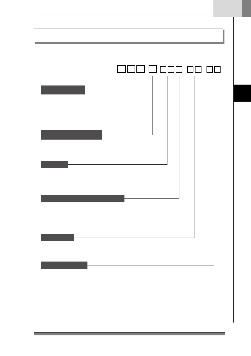
Models in this series are identified by the following model naming method.
English
Model Number:
CD-S -
Model name
500 : Standard model
50 1 : Built-in auto cutter model
503 : Built-in auto cutter and rewinder
model
Power source type
A: AC adapter type
S: Built-in AC adapter type
Interface
PA : Parallel IEEE1284 compatible
RS : Serial RS-232C compatible
UB: USB
Region (Characters + power cord)
J : Japan
E : Europe
U : North America
C : China
Case Color
WH : Cool white
BK : Black
-
Introduction
Black mark sensor
None : No sensor
M1 : Left sensor for paper reverse
M2 : Right sensor for paper reverse
M3 : Left sensor for paper surface
M4 : Right sensor for paper surface
13
Page 16
Chapter1
Introduction
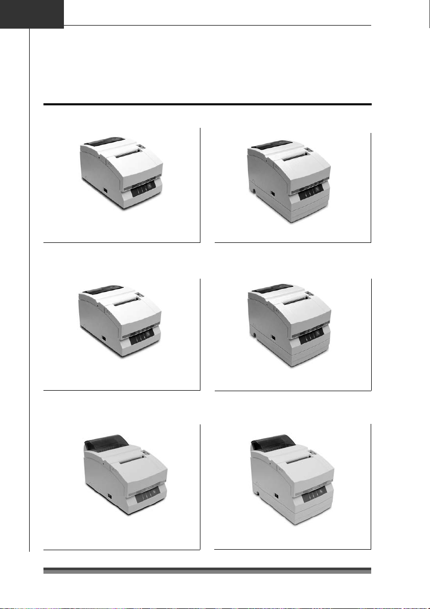
Explanation of models
Examples of models
Standard model (AC Adapter type)
CD-S500A--
Auto cutter equipped model
(AC Adapter type)
CD-S501A--
Auto cutter and rewinder equipped
model (AC Adapter type)
Standard model
(Built-in AC adapter type)
CD-S500S--
Auto cutter equipped model
(Built-in AC adapter type)
CD-S501S--
Auto cutter and rewinder equipped
model (Built-in AC adapter type)
14
CD-S503A-- CD-S503S--
Page 17
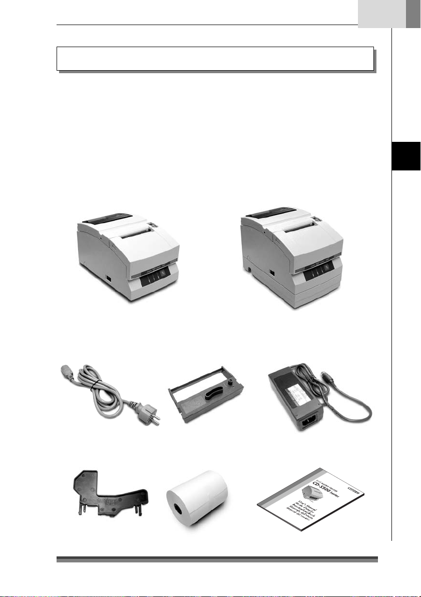
Checking the Accessories
Check to make sure that the following accessories are included with your printer.
Printer: 1
AC adapter: 1
(CD-S500A series only)
Power cord: 1
Ribbon cassette: 1
Printer: 1
AC adapter type
Partition: 1
Slip prevention rubber feet: 4
(CD-S500S and CD-S501S only)
Sample roll paper: 1
User’s Manual (this document)
Built-in AC adapter type
English
Introduction
* The AC adapter is set inside the AC
adapter case.
AC adapter Power cord Ribbon cassette
Partition Sample roll paper User’s Manual
(this document)
15
Page 18
Chapter2
Names and Functions of Parts
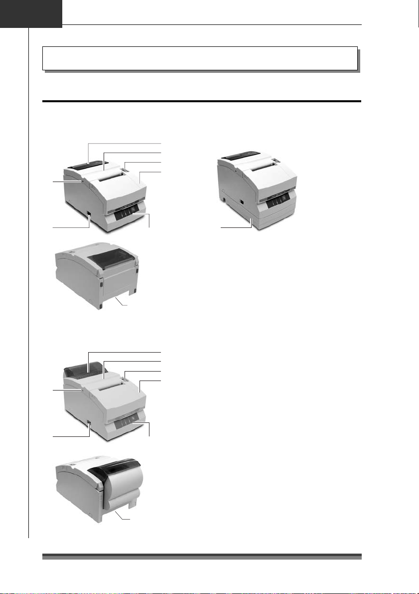
Exterior
AC adapter type
Standard and auto cutter equipped
models
6
Names and Functions of Parts
Built-in AC adapter type
1
2
3
4
5
Auto cutter and rewinder equipped
model
6
5
Operation panel
(see page 18)
Rear connectors
(see page 19)
1
2
3
4
Operation panel
(see page 18)
Rear connectors
(see page 19)
7
1 Paper check window
It can be used to check the amount of
paper left on the roll.
2 Rear cover
It can be opened to set or to replace a
paper roll.
3 Rear cover open lever
It is a lever used to open the rear cover.
Pull the lever towards you to open the rear
cover.
4 Front cover
It can be opened to set or replace the
ribbon cassette.
5 Power switch
It turns the printer power on and off.
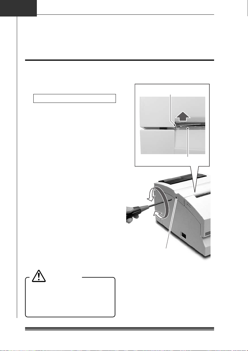
6 Cutter lock clearing screw hole
When the rear cover cannot be opened
because the blade of the auto cutter
protrudes after a malfunction or as a result
of a paper jam, turn this screw with a
Phillips head screw driver to return the
blade.
7 AC adapter case
This is installed only for the built-in AC
adapter type.
16
Page 19
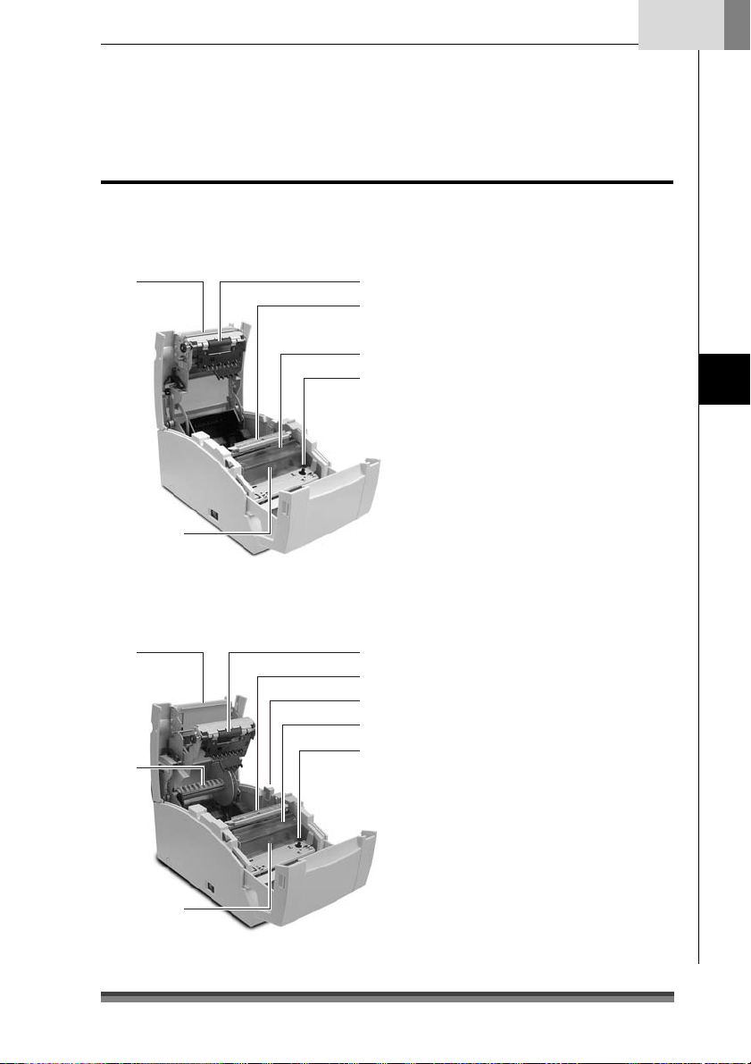
Interior
AC adapter type
Standard and auto cutter equipped
model
8
6
Auto cutter and rewinder equipped
model
8
7
1 Platen unit
1
2
4
5
1
2
3
4
5
In the standard and auto cutter equipped
models, it is combined with 8 the auto
cutter.
2 Paper cut bar
It is used to cut the paper manually.
3 Platen open lever
It is a lever used to open the platen unit
on the rewinder equipped model. Open
the platen unit by pulling it towards you.
4 Print head cover
5 Ribbon cassette drive shaft
6 Print head
7 Rewinder shaft
It rewinds the copy side of the copy roll
paper.
8 Auto cutter unit
It automatically cuts the paper after
printing is completed. The cut action is
set by a command in Soft SW Setting
Mode.
English
Names and Functions of Parts
6
17
Page 20
Chapter2
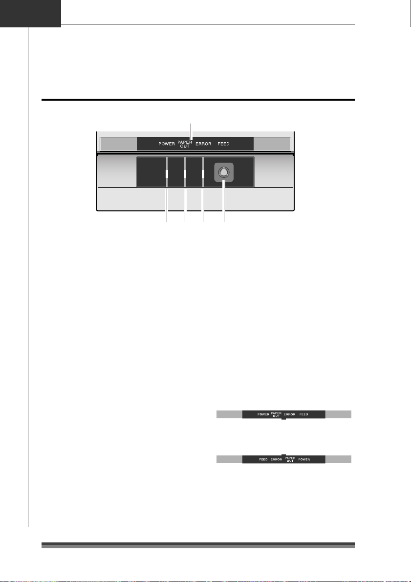
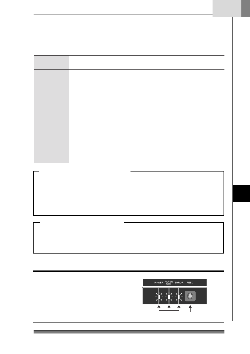
Operation Panel
Names and Functions of Parts
5
123 4
1 POWER LED (Green)
It is lit when the power is supplied. When
maintenance mode is set or there is an
error indication, it is either lit or flashing.
2 PAPER OUT LED (Orange)
It is lit in paper out status. When
maintenance mode is set or there is an
error indication, it is either lit or flashing.
3 ERROR LED (Orange)
It is lit when the rear cover or front cover
is open. When maintenance mode is set
or there is an error indication, it is either
lit or flashing.
4 FEED Switch
When this switch is pressed once, paper
feeds (1 line). If it is held down, paper
feeds continuously until it is released.
And when there is a printer error, pressing
this switch can cancel the error status.
5 LED NAME SHEET
This sheet is used reversed according to
the printer installation method. See
Vertical Installation and Wall Mounted
Installation (page 23).
Display when installed horizontally
Display when installed vertically or
wall mounted
18
Page 21
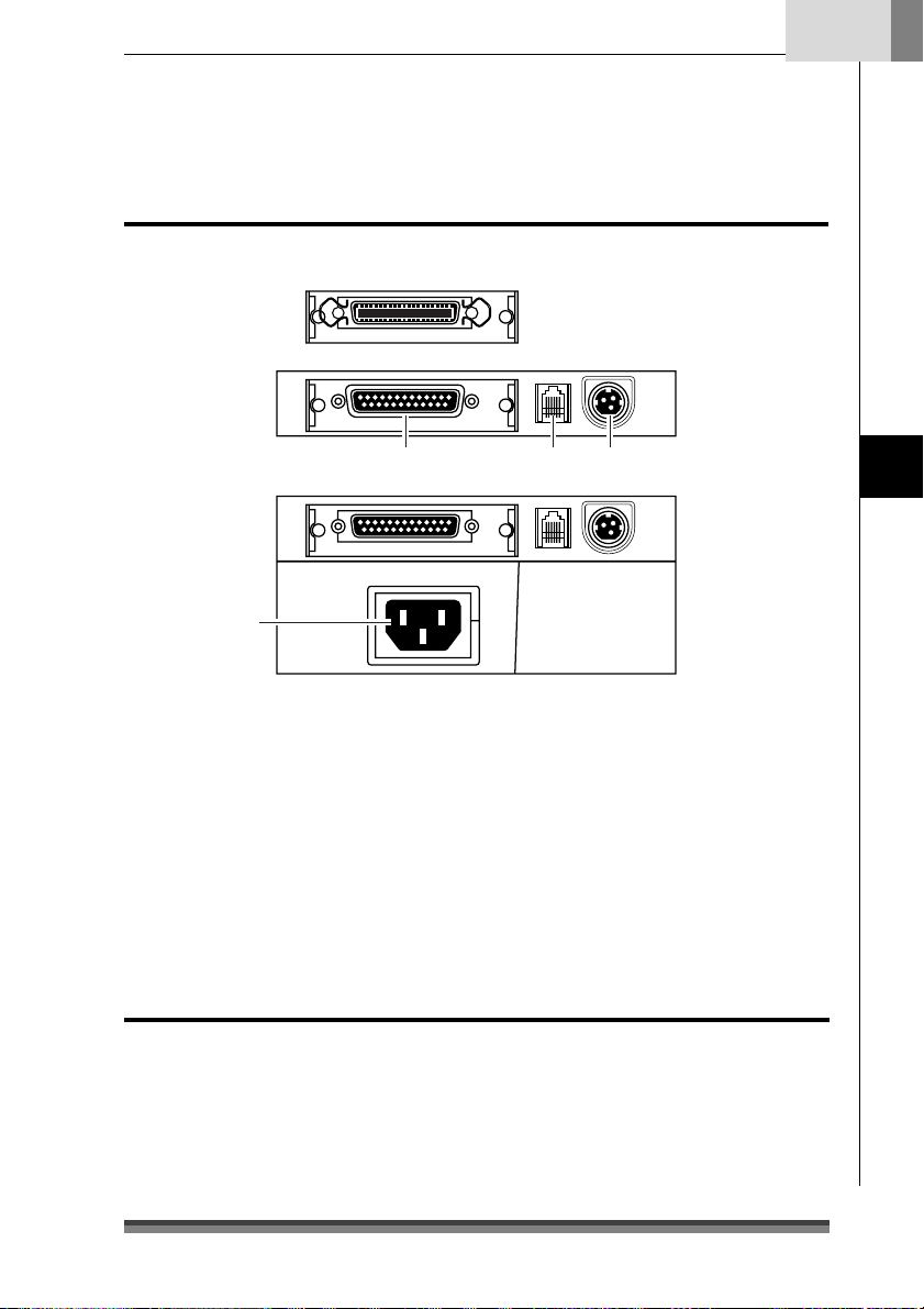
Rear Connectors
English
AC adapter type
Parallel (IEEE1284) interface
Serial (RS232C) interface
Built-in AC adapter type
4
1 Interface connector
It is connected to either a serial (RS232C) or parallel (IEEE1284) interface cable.
* A USB interface replaced by a serial or parallel interface will be available as a factory
option.
2 Drawer kick connector
It is connected to a cable from the drawer.
3 Power source connector
It is connected to a cable from the AC adapter.
4 Power source inlet
It is connected to the power cord.
123
Names and Functions of Parts
Others
Built-in Buzzer
A buzzer sounds when the FEED switch is operated and when there is an error.
The buzzer can be switched between enabled and disabled in Soft SW setting mode.
User Memory
Logo data or text data prepared by the user can be stored in memory.
This stored data remains in memory even after the power is turned off.
19
Page 22
Chapter3
Preparing the Printer
Connections
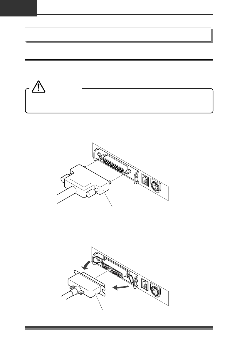
Connecting the Interface Cable
Turn off the power to the printer and insert the connectors being careful about their
orientation.
Caution
Always hold the connector when pulling out a cable.
Install the interface cable so that it will not be caught on your shoes etc.
Connecting the serial (RS232C) interface cable
Make sure that you insert it firmly and fix it in place by tightening the screw.
Serial (RS232C) interface cable
Connecting the parallel (IEEE1284) interface cable
Make sure that you insert it firmly and fix it in place by turning the attachment screws in
the direction shown by the arrow.
Parallel (IEEE1284) interface cable
20
Page 23
English
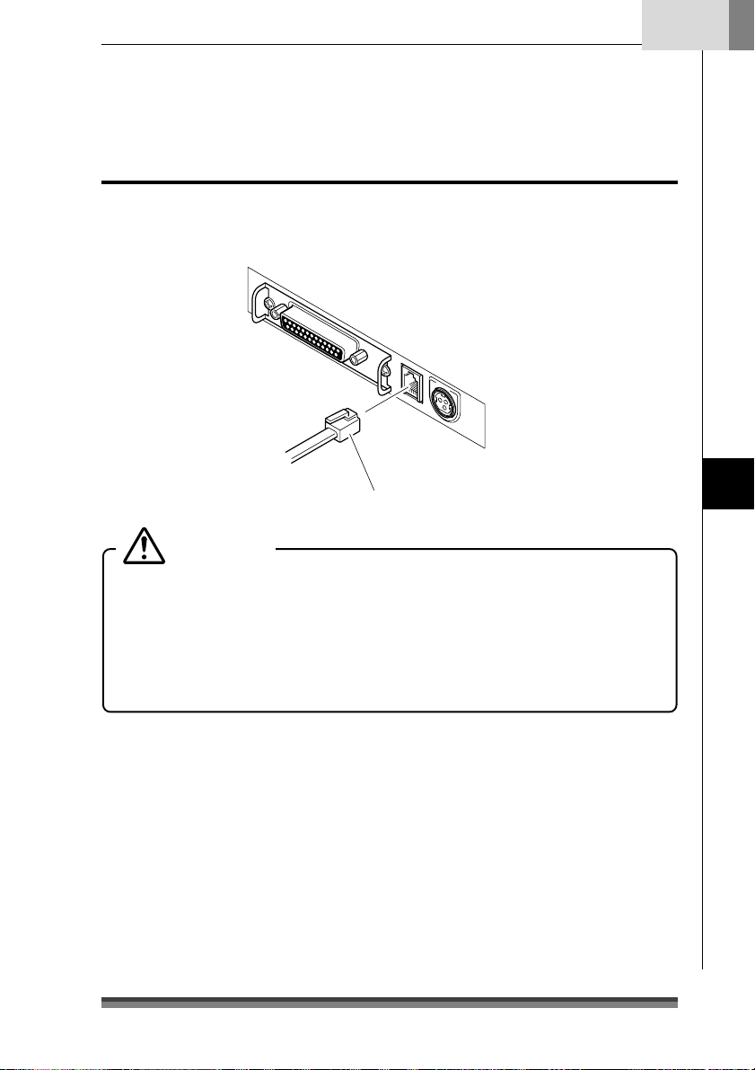
Connecting the Drawer
Match the top and bottom of the drawer kick connector with the cable terminal and insert
it firmly until you hear a click.
Drawer kick cable
Caution
Connect only a specialized drawer. (Do not connect a telephone line.)
Output is impossible during printing.
Drawer 1 and drawer 2 cannot be driven simultaneously.
Use a drawer use solenoid that is at least 24Ω. Make sure that the output current
is not higher than 1A. This may cause a malfunction or burn damage.
Install the drawer kick cable so that it will not be caught on your shoes etc.
See page 48 for detailed specifications of the interfaces.
Preparing the Printer
21
Page 24
Chapter3
p
Preparing the Printer
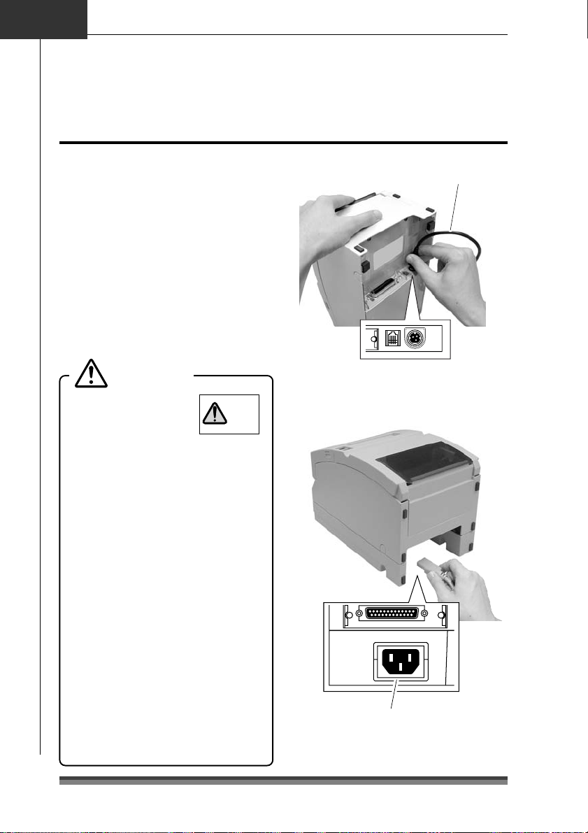
Connecting the Power
1.Make sure that the printer power
switch is set to OFF.
2.If your printer is an AC adapter type,
insert the AC adapter cable connector
with its flat side upwards into the
power connector on the rear surface
of the printer.
If your printer is a built-in AC adapter
type, insert the plug on the power
cord into the AC inlet on the back
surface of the printer.
Caution
Do not use an AC
adapter other than
the stipulated product
(Model 51AD).
Always hold the connector when
inserting or removing the cable
connector of the AC adapter.
Stretching the power cord by pulling
it will damage it, causing fire, electric
shocks, or a break in the conductor.
When lightening is striking nearby,
remove the plug of the power cord
from the outlet. Lightening will cause
fire or electric shock.
Do not place the power cord near a
heating device. The cover of the power
cord will melt, causing fire or electric
shock.
When the printer will not be used for
a long period, be sure to remove the
plug of the power cord from the outlet
to guarantee safety.
Isolate the AC power source from
other devices that generate noise.
DC 24V
51 AD
ONLY
AC adapter cable
Flat side of the cable is u
AC adapter type
AC inlet
Built-in AC adapter type
.
22
Page 25
English
Protrusion
Part B
Installation
This printer can be installed horizontally or vertically and can be wall mounted.
But according to the model you are using, there may be restrictions on how it is installed.
Refer to the following table.
Horizontal Vertical Wall Mount
Standard model (AC adapter type) Yes No Yes*
Standard model (Built-in AC adapter type)
Auto cutter equipped model (AC adapter type) Yes No Yes*
Auto cutter equipped model (Built-in AC adapter type)
Auto cutter and rewinder equipped model
(AC adapter type)
Auto cutter and rewinder equipped model
(
Built-in AC adapter type
*1: Accessory rubber feet must be used to prevent slipping.
*2: The optional specialized wall mount unit is necessary to mount it on the wall.
)
Ye s Yes *
Ye s Yes *
Ye s N o N o
Ye s N o N o
1
1
Vertical installation and wall mounted installation
To install the printer vertically or wall mounted, remove the Chassis Platen L Spring used to
open the rear cover. And reverse the LED name sheet on the operation panel to use it with
the vertically installed and wall mounted display.
Yes *
Yes *
2
2
2
2
Preparing the Printer
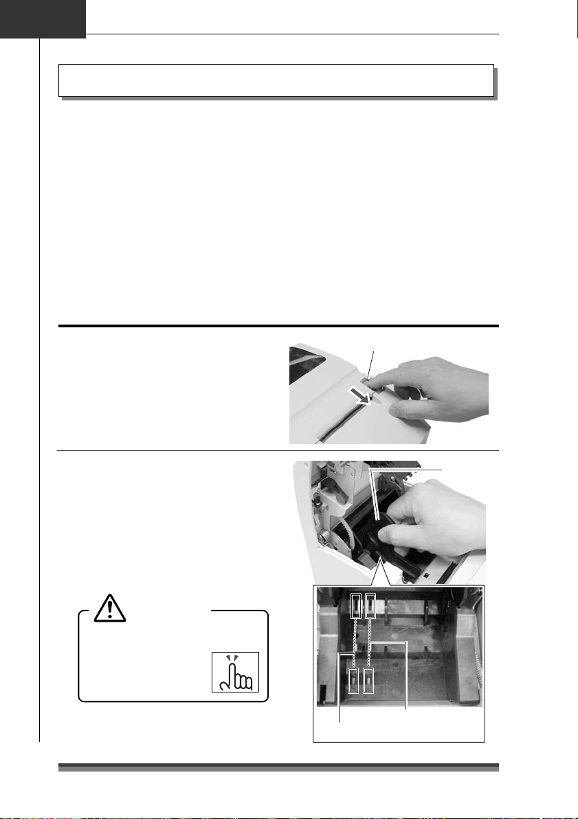
Removing the Chassis Platen L Spring
1.
Open the rear cover. Do this carefully, because
the cover snaps open vigorously.
2.
Lift part A with the fingers of your right hand.
3.
Switch the Chassis Platen L Spring that you have
raised from your right thumb to your left thumb
to hook the protrusion on the end of the Chassis
Platen L Spring inside part B of the printer.
Caution
Chassis Platen L Spring with strong
repulsive force is used. Be very careful
that it does not slip off your finger
causing an injury.
LED Name Sheet
Remove and reverse the sheet then reinsert the
protruding part of the center of the sheet in the
printer and push in both ends.
Part A
Chassis
Platen
L Spring
23
Page 26
Chapter3
Preparing the Printer
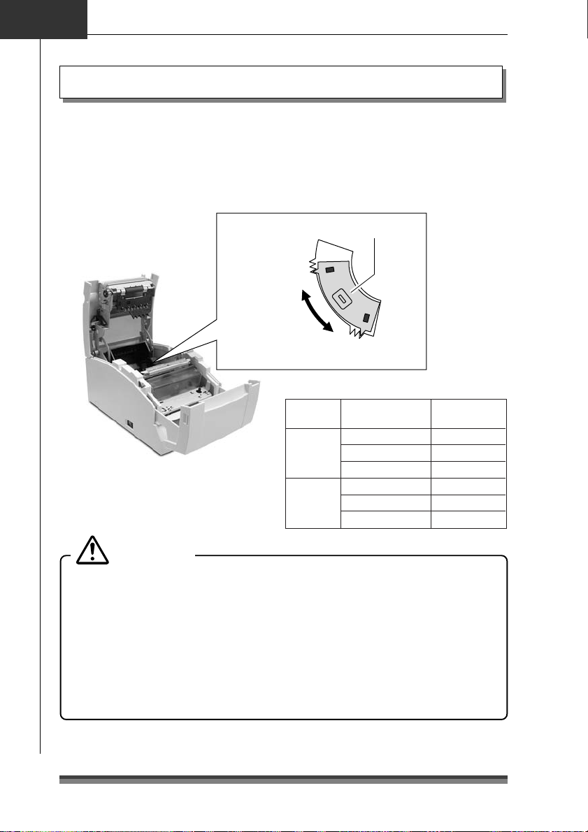
Setting the Paper Near End Sensor
Change the sensor location according to the way the printer is installed and the interior
diameter of the roll paper you are using. Referring to the following table, set it at a
location suited to the usage environment by moving it to the left and right while pushing
the concave part of the center of the sensor with your finger. (When shipped from the
factory, it is set at φ24mm.)
Paper near end sensor
When installed
vertically and
wall hung
6
5
4
3
2
When installed horizontally
1
Installation
method
Horizontal
Vertical
(wall mounted)
Remaining roll
paper (mm)
Approx. φ22
Approx. φ24
Approx. φ27
Approx. φ27
Approx. φ24
Approx. φ22
Caution
The remaining roll paper (external diameter of the roll paper) differs greatly
according to the type of roll paper used. Use these values only as guidelines.
When the sensor has detected the remaining roll paper during printing, the printer
stops printing after it has printed all the data that it had received.
If you are using a model with parallel (IEEE1284) interface specifications, you can
select sensor enabled/disabled in Soft SW Setting Mode.
If you are using a model with serial (RS232C) interface specifications, it is always
enabled.
24
Sensor location
1
2
3
4
5
6
Page 27
English
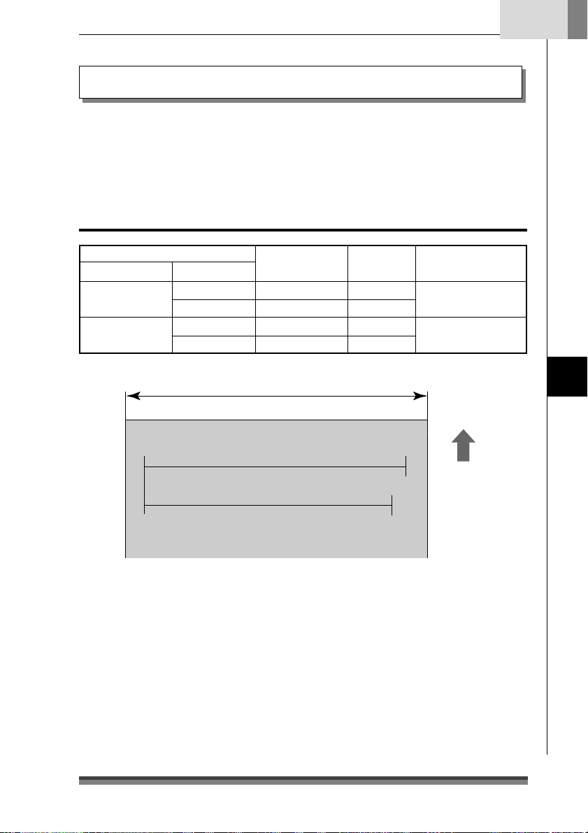
Setting the Paper Width and Printing Line Column Number
The printing dot line columns are changed as follows by setting the “Paper Width” of the
roll paper used, the “Number of col.” and the “Font Select” in Soft SW Setting Mode.
For details about setting, see Soft SW Setting Mode (page 35).
When setting Paper Width of 76.2mm
Soft SW Setting Mode
Number of col. Font Select
40/33
42/35
9Ω9 dots 3 dots 33 columns
7Ω9 dots 3 dots 40 columns
9Ω9 dots 2 dots 35 columns
7Ω9 dots 2 dots 42 columns
Paper width: 76.2mm
When Number of col. 40/33 are selected: 400 dots
When Number of col. 42/35 are selected: 386 dots
Space between
characters
Printing line
columns
Full columns
400 dots
386 dots
Preparing the Printer
Paper feed
direction
25
Page 28
Chapter3
Preparing the Printer
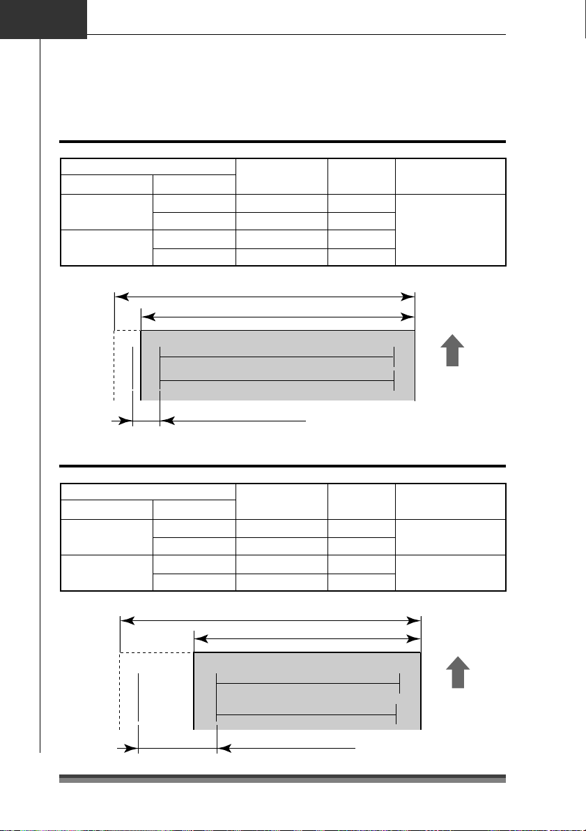
Setting Paper Width and Printing Line Columns
When setting Paper Width of 69.5mm
Soft SW Setting Mode
Number of col. Font Select
40/33
42/35
9Ω9 dots 3 dots 30 columns
7Ω9 dots 3 dots 36 columns
9Ω9 dots 2 dots 32 columns
7Ω9 dots 2 dots 40 columns
When Number of col. 40/33 are selected: 360 dots
When Number of col. 42/35 are selected: 360 dots
Right offset: 40 dots
Space between
characters
Paper width: 76.2mm
Paper width: 69.5mm
When setting Paper Width of 57.5mm
Soft SW Setting Mode
Number of col. Font Select
40/33
42/35
9Ω9 dots 3 dots 25 columns
7Ω9 dots 3 dots 30 columns
9Ω9 dots 2 dots 27 columns
7Ω9 dots 2 dots 33 columns
Space between
characters
Printing line
columns
Printing line
columns
Full columns
360 dots
Paper feed
direction
Full columns
300 dots
298 dots
26
Paper width: 76.2mm
Paper width: 57.5mm
When Number of col. 40/33 are
selected: 300 dots
When Number of col. 42/35 are
selected: 298 dots
Right offset: 100 dots
Paper feed
direction
Page 29
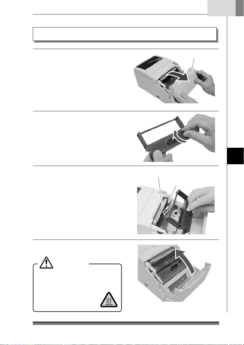
Installing the Ribbon Cassette
English
.Open the front cover of the printer.
1
Insert your fingers into the dents at
opposite ends of the front cover to
open it with both hands.
2.Turn the ribbon cassette knob in the
direction shown by the arrow to fully
stretch the ribbon.
3.Insert the cassette into the printer
until a click is heard so that the ribbon
is between the paper cut bar and the
print head cover. If it difficult to insert,
turn the ribbon cassette knob again.
Front cover
Preparing the Printer
Paper cut bar
Print head cover
4.Close the front cover.
Caution
Be very careful not to let your hands
touch the print head cover when
replacing the ribbon cassette. When the
print head has become
heated, there is a danger of
it burning your hand.
27
Page 30
Chapter3
Preparing the Printer
Installing Roll Paper
The following are the types of roll paper that can be used by this printer.
Types: 1P roll paper
2P copy roll paper (1 original + 1 copy)
3P copy roll paper (1 original + 2 copies)
(2P and 3P copy roll paper are only usable on models equipped with auto
cutter and rewinder.)
Paper widths: 76.2 (±0.7)/69.5 (±0.6)/57.5 (±0.5)mm
Roll diameter: φ30mm to φ83mm
Core diameter: Interior diameter φ10
Paper thickness: 1P 0.06 to 0.085mm
Copy paper 0.05 to 0.20mm (total thickness)
But the total thickness that can be cut is from 0.05 to 0.14mm.
Standard and Auto Cutter Equipped Models
+2
mm, exterior diameter φ27mm or less
–0
Installation method
1.Pull the rear cover open lever towards
you to open the rear cover.
2.Set the attached partition in place if
the roll paper you are using is 69.5mm
wide or 57.5mm wide.
Change the paper width by changing
the value set as the width using the
Soft SW Setting Mode.
(See page 35)
Caution
When setting the roll paper, be
careful not to cut your
hand on the edge of
the paper.
Rear cover open lever
Partition
Location set for width of 57.5mm
Location set for width of 69.5mm
28
Page 31

English
3.Place the roll paper and pull the end
of the roll paper directly towards you
as shown in the figure.
Hold the center of the roll paper to pull
it as straight as possible so that one of
the sides of the paper does not slacken.
4.Maintaining tension in the roll paper,
firmly close the rear cover until you
hear a click.
Paper feeds automatically and stops
at the print start position.
Caution
Be very careful not to let
the rear cover catch your
hands when closing the rear
cover.
1P roll paper
Rear cover
Roll paper that is
gently pulled taut.
Preparing the Printer
5.Tear off surplus paper by holding one
side of the end of the roll paper and
pulling it towards you.
Caution
Do not insert any foreign
objects such as a paper clip
into the cutter unit.
29
Page 32
Chapter3
Preparing the Printer
Installing Roll Paper
Auto Cutter and Rewinder Equipped Model
Installation Method
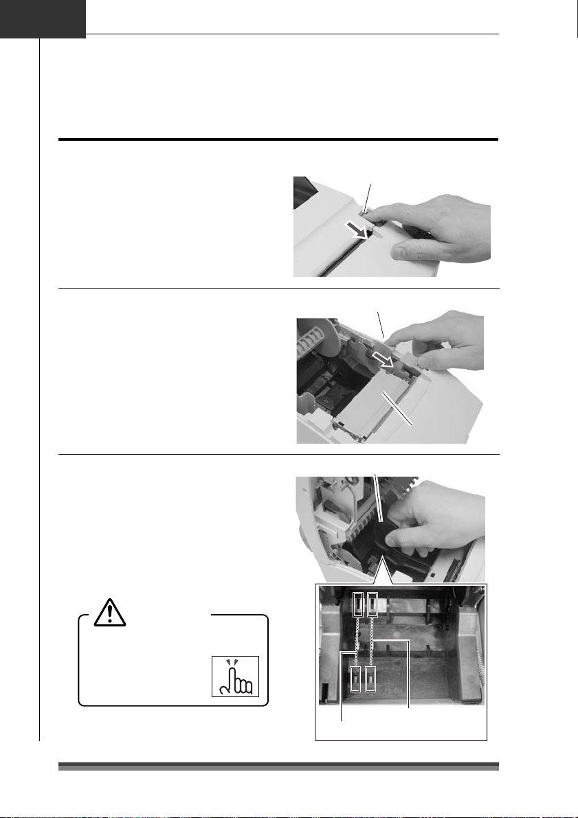
1.Pull the rear cover open lever towards
you to open the rear cover.
Rear cover open lever
2.Then pull the platen open lever
towards you to open the platen unit.
3.Set the attached partition in place if
the copy roll paper you are using is
69.5mm wide or 57.5mm wide.
Change the paper width by changing
the value set as the width using the
Soft SW Setting Mode.
(See page 35)
Caution
When setting the roll paper, be
careful not to cut your
hand on the edge of
the paper.
Platen open lever
Platen unitPlaten unit
Partition
30
Location set for width of 57.5mm
Location set for width of 69.5mm
Page 33
English
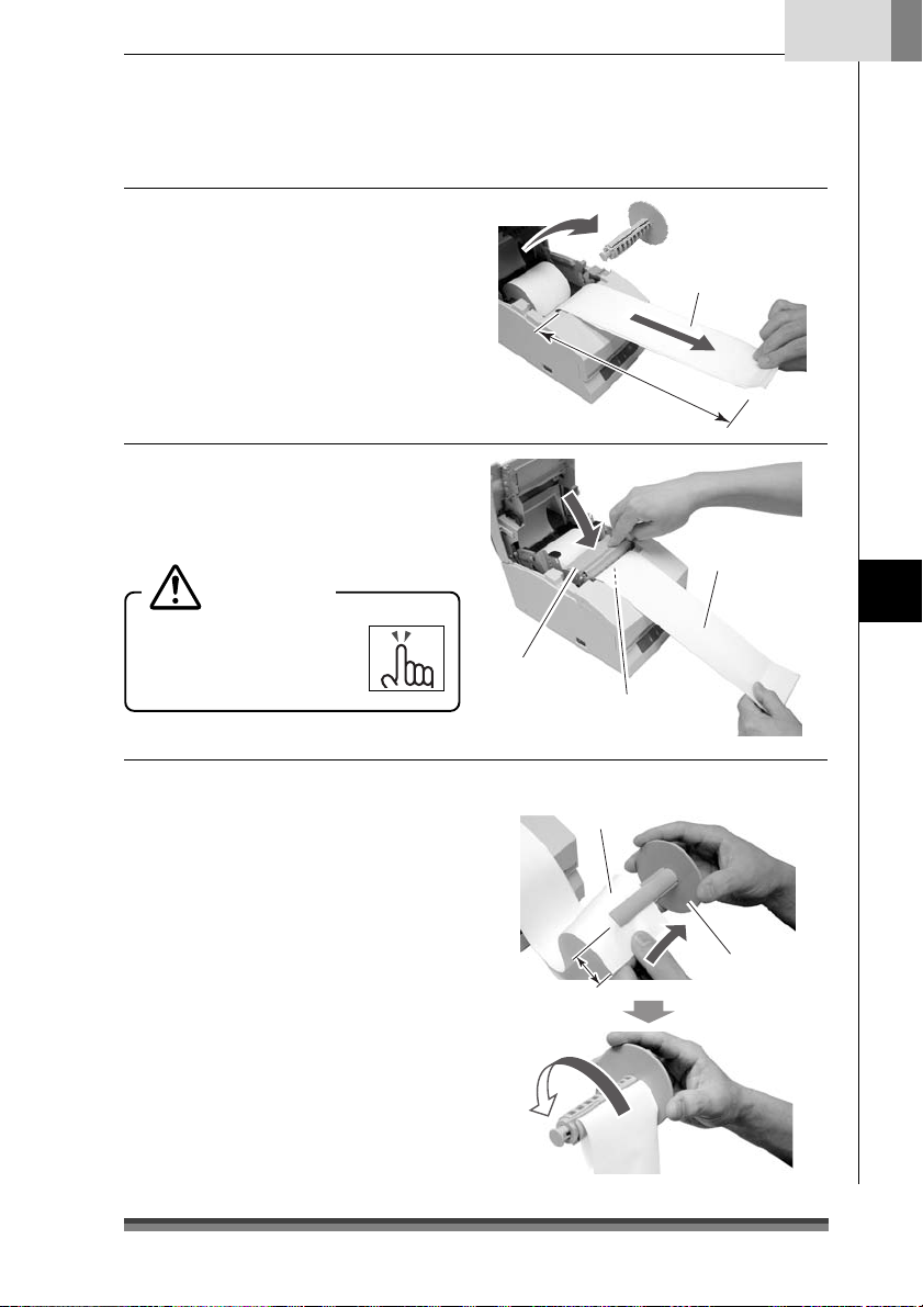
4.After removing the rewinder shaft,
install the copy roll paper and pull the
end of the roll paper straight towards
you for about 30cm as shown in the
figure.
Hold the center of the roll paper to pull it
as straight as possible so that one of the
sides of the paper does not slacken.
5.Maintaining light tension in the copy
roll paper, firmly close the platen unit
until you hear a click.
Caution
Be very careful not to let
your hands touch the blade
on the paper cutter bar.
6.
Set one side of the copy roll paper
(copy side) on the rewinder shaft as
shown in the figure, and tightly wind
it about 2 rotations in the direction
shown by the arrow.
Check to make sure that the copy roll
paper rotates with the rewinder shaft.
Rewinder shaft
2P or 3P copy roll paper
About 30cm
Roll paper that is
gently pulled taut.
Preparing the Printer
Platen unit
Be careful of the paper cut bar.
Copy roll paper
(copy side)
Rewinder shaft
Protrudes
about 5cm
Wind it about twice
31
Page 34

Chapter3
Preparing the Printer
Installing roll paper
7. Being careful not to let the copy roll
paper set on the rewinder shaft
slacken, place the roll paper in the
grooves on both sides.
Turn the flange on the rewinder shaft
in the direction shown by the arrow
and make sure that the copy roll
paper rotates with the rewinder shaft.
Taking up slack while checking that
the copy roll paper winds.
8.With the other side of the copy roll
paper (original side) pulled lightly
taut, close the rear cover firmly until
you hear a click.
Hold the center of the roll paper to pull
it as straight as possible so that one of
the sides of the paper does not slacken.
Paper feeds automatically and stops
at the print start position.
Caution
Be very careful not to let
the rear cover catch your
hands when closing the rear
cover.
9.Tear off surplus paper by holding one
side of the end of the roll paper and
pulling it towards you.
Caution
Do not insert any foreign
objects such as a paper clip
into the cutter unit.
Rear cover
Roll paper that is
gently pulled taut.
32
Page 35

English
Operation when the cover is opened and closed
Operation when the front cover is opened and closed
Opening: During printing, the printing stops and if it is in red printing status, the ribbon
is switched to the black ribbon status, moves to the centering location, and
becomes the condition you can replace the ribbon cassette.
Closing: If it was red printing status when it was opened, the ribbon returns to red status
and if there is printing data, printing restarts.
Operation when the rear cover is opened and closed
Opening: During printing, the printing stops and the ribbon moves to the centering
location and remains in stand by. On models equipped with a rewinder, if the
cover is opened with paper set, the paper is fed forward about 1 inch then
returns to the centering position.
Closing: After print operation and cut operation have been initialized, it performs paper
feed check, and if there is printing data, printing restarts.
Preparing the Printer
Caution
If a cutter problem is caused by a paper jam etc., the printer may stop with the
cutter blade protruding so that the rear cover cannot be opened. In this case,
press the FEED switch to eliminate the cutter problem without trying to force it
open. If the problem is not eliminated by pressing the switch, insert a screw driver
in the hole on the left side surface of the rear cover and rotate it to manually
restore the cutter blade, then open the cover. (The blade will be restored by turning
it to either the left or the right.)
Be careful of the manual paper cut bar in particular, to make sure that your fingers
are not caught when opening and closing the cover.
Opening the rear cover during printing causes malfunctions of the printer head or
cutter unit. Make sure that printing has stopped before you open the rear cover.
To close the rear cover, close it while holding the end of the paper so that the
paper is not slack or bent inside the printer.
33
Page 36

Chapter4
Maintenance Mode
Maintenance Mode
The settings of the printer can be changed according to its usage environment in
maintenance mode. And it is also possible to change their settings back to the initial
factory shipping setting or to adjust the cut position after printing in this mode.
And the content of the settings can be confirmed in demonstration printing mode.
To change the settings in maintenance mode, print and check the present settings.
Demonstration printing mode
Setting the mode
Turning the power on while pressing the FEED switch with the front cover and the rear
cover both closed starts demonstration printing mode and the “demonstration printing
and the present printing settings” are printed.
Setting maintenance mode
1.Set maintenance mode by turning on
the power while pressing the FEED
switch with the front cover open and
the rear cover closed, then releasing
the FEED switch.
2.The POWER LED flashes as the printer
enters maintenance mode.
Close the front cover in this status.
Flashing
Power switch
Front cover open
FEED switch
Types of maintenance mode
There are the following four types of maintenance mode.
Each mode is selected according to the number of times the FEED switch is pressed from
maintenance mode.
HEX Dump Mode: Press the FEED switch 0 times and reopen and close the front cover.
Soft SW Setting Mode: Press the FEED switch 1 time and reopen and close the front cover.
Initial Factory Shipping Mode: Press the FEED switch 2 times and reopen and close
the front cover.
Cut Position Adjustment Mode: Press the FEED switch 3 times and reopen and close
the front cover.
34
Page 37
Flashing
Press once
HEX Dump Mode
Setting the mode
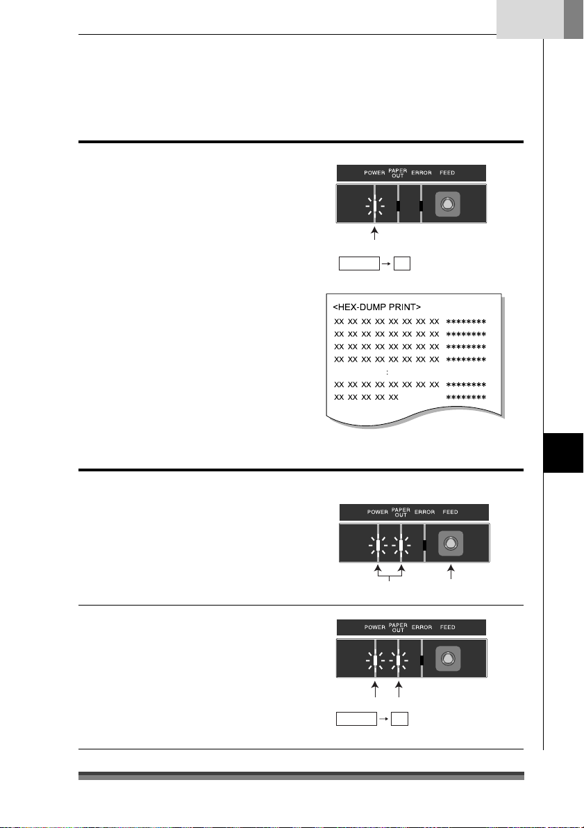
If the front cover is reopened and closed
in maintenance mode (POWER LED is
flashing), the POWER LED stops flashing
and remains lit, and the printer enters
HEX Dump Mode.
After printing the title, it stands by to
receive data.
To leave HEX Dump Mode, turn off the
printer power then turn the power on again
with the front and rear covers both closed.
English
Reopening and closing the front cover:
Flashing Lit
Soft SW Setting Mode
Setting the mode
1.If the FEED switch is pressed once in
maintenance mode (POWER LED is
flashing), the POWER LED and PAPER
OUT LED start flashing.
2.If the front cover is reopened and
closed in this status, the POWER LED
and PAPER OUT LED stop flashing to
and remain lit, and after the title and
top items have printed, it enters Soft
SW Setting Mode.
Maintenance Mode
Reopening and closing the front cover:
Flashing Lit
35
Page 38

Chapter4
Maintenance Mode
Soft SW Setting Mode
Operating method
Press the FEED switch (less than 2 seconds):
The setting changes.
The present set value is changed and the
same item is reprinted. (Press the FEED
switch, and when the buzzer sounds once,
release it.)
Pressing the FEED switch continuously (2
seconds or more):
Moves to the next item.
It prints the present set value of the next
item. (Press the FEED switch, and when the
buzzer sounds three times, release it.)
Opening/closing the front cover:
After saving the set values, it reprints all
items from the top and returns to normal
power on status.
* If the power is turned off without opening
and closing the front cover, the setting
change is invalid.
* If the paper runs out during the change,
set the paper and close the rear cover to
continue the process.
Operations
Press the
FEED Switch
Press and
hold the FEED
Switch
<Soft-Switch Setting>
Press Feed
Change PARM.
Press Feed For 2S
Next Item
F.Cover Open/Close
Save & Exit
<Soft Control-SW>--------------------
Command Type —EPSON
Number of Col. —40/33
Font Select —7
Paper Plies —OFF
Paper End —ENB
Paper Near-End —ENB
Slashed Zero —OFF
Print Direct. —BI-DIR
Auto LF —OFF
Code Page —437
Buffer Size —4K
Init Signal —ENB
Buzzer —ON
<Interface-SW>------------------------
Baud Rate —9600
Data Length —8bit
Parity Bit —NONE
Stop Bit —1bit
Protocol —DTR
<Mechanical-SW>--------------------
Paper Width —76.2
Auto-Cutter —PAR.
Color Ribbon —ON
Take-Up Device —ON
Black Mark —DIS
Command Type —EPSON
Command Type —STAR
Number of Col. —40/33
×
9
36
Press and
hold the FEED
Switch
Font Select —7
×
9
Press the
FEED Switch
Font Select —9
×
9
Example of a change of the Command Type to
STAR and the Font Select to 9×9.
Page 39

Setting Mode Table
Soft Control-SW
Set item Initial value Setting value Remarks
Command Type EPSON EPSON
Number of Col. 40/33 40/33
Font Select 7x9 7Ω9
Paper Plies OFF OFF
Paper End ENB ENB
Paper Near-End ENB ENB
Slashed Zero OFF OFF
Print Direct. BI-DIR BI-DIR
Auto LF OFF OFF
Code Page 437
STAR
CBM1
CBM2
42/35
9Ω9
DIS
DIS
ON
UNI-DIR
ON
437,
KATAKANA,
850, 860
863, 865
852, 866
857, 858
WPC1252
The emulation is selected from EPSON/STAR/
CBM1/CBM2.
Number of full dot in full column is 200 dots. For the
number of line columns based on the paper width, see
“Setting the Paper Width and Printing Line Column Number”.
The initial font size is selected immediately after the
power is turned on.
Copy mode is selected.
OFF/2P/3P can be selected. But when 3P is set, the
2P
printing speed is low.
3P
The PE signal enabled/disabled is set at paper end when
only the centro-interface is set as enabled. During
enabled status, BUSY, PE, FAULT are output and printing
stops at paper out. During disabled status, only BUSY is
output and printing stops at paper out.
The PE signal enabled/disabled is set at paper near end
when only the centro-interface is set as enabled. During
enabled status, PE, FAULT are output and printing
continues. During disabled status, nothing is output and
printing continues.
It sets whether or not slash is used with the numeral 0
(zero).
Designates printing direction. When BI-DIR is selected,
printing starts from the closer of the left and right ends
of the next printing line from the print stop location.
During UNI-DIR printing is usually done from the left end.
The LF operation during CR code reception is selected.
When ON, LF does not operate; when OFF, LF operates.
CR: Carriage Return LF: Line Feed
The code page is selected.
English
Maintenance Mode
37
Page 40

Chapter4
Maintenance Mode
Soft SW Setting Mode
Set item Initial value Setting value Remarks
Buffer Size
Init Signal
Buzzer
n
Interface-SW (Displayed only when the serial board is mounted)
Set item Initial value Setting value Remarks
Baud Rate
Data Length
Parity Bit
Stop Bit
Protocol
4k
ENB
ON
9600
8 bit
NONE
1 bit
DTR
40byte
4Kbyte
ENB
DIS
ON
OFF
19200
9600
4800
2400
1200
8 bit
7 bit
NONE
EVEN
ODD
1 bit
2 bit
DTR
X-ON-OFF
The receiving buffer size is selected.
Selects enabled (ENB)/disabled (DIS) of the printer
initialized signal (PRIME) during centro-interface.
Selects enabled (ENB)/disabled (DIS) of the 25pin reset
signal during serial interface.
Selects buzzer sound when an abnormality occurs as
enabled (ON)/disabled (OFF).
Sets the baud rate of the serial interface.
Sets the character length of the serial interface.
Sets the communication parity of the serial interface.
Sets the stop bit of the serial interface.
n
Mechanical-SW
Set item Initial value Setting value Remarks
Paper Width
Auto-Cutter
Color Ribbon
76.2
PAR.
ON
76.2
69.5
57.5
OFF
FREE
FULL
PAR.
ON
OFF
Selects the paper size.
Selects the cutter operation.
When it is OFF, the FULL/PAR. commands do not start
cutting.
In FREE status, cutting is done according to the
FULL/PAR. commands.
In FULL status, full cut is always done by both the
FULL/PAR. commands.
In PAR status, partial cutting is always done by both the
FULL/PAR. commands.
Selects the color function.
During OFF, the change color command is ignored.
38
Page 41
Set item Initial value Setting value Remarks
g
Take-Up Device
Black Mark
ON
DIS
ON
OFF
DIS
TYPE1
TYPE2
Selects the rewinder function.
During OFF, the rewinder motor does not operate.
Selects enabled (TYPE1, TYPE2)/disabled (DIS) of the
black mark control function.
In TYPE1 status, auto paper length measuring operation
is done and the black mark is fed to the paper cut
position when the power is turned on.
GS FF/FF commands are available in the status.
It is used for formatting the black mark at the edge of
the page.
In TYPE2 status, measuring operation is not done when
the power is turned on.
The auto paper length paper measuring, initial paper
positioning and paper cutting operations are controlled
by the command from a host PC.
FS(L command only is available in the status.
It is used for formatting the black mark in the middle of
the page. (TYPE2 status is not available in STAR and
CBM1/2 modes.)
Concerning Mechanical-SW operation
Functions that are not supported by the specifications at time of shipping have no
impact on printer operation even when the settings are changed.
Examples) Items set for the Auto-Cutter in models that are not equipped with an
Auto-Cutter.
Change of the setting of the Take-Up Device in models to which rewinder
specifications do not apply.
English
Maintenance Mode
Concerning Auto-Cutter operation
The minimum cutting interval is 1/2 inch (3 lines with 6LPI).
Once a cut command has been executed, even if a command is sent before the paper
has fed at least 1/2 inch, the cut command is ignored so the cut action cannot be
executed.
Initial Factory Shipping Mode
Setting the mode
1.Pressing the FEED switch twice in
maintenance mode (POWER LED is
flashing) causes the POWER LED, PAPER
OUT LED, and the ERROR LED to begin
to flash.
Flashin
Press twice
39
Page 42

Chapter4
g
Maintenance Mode
Initial Factory Shipping Mode
2. Reopening and closing the front cover in
this status switches the POWER LED,
PAPER OUT LED, and the ERROR LED
from flashing to continuously lit status.
3. Pressing the FEED switch for 3 seconds or
more restores settings to the factory
shipping (initialized) status.
Cut Position Adjustment Mode
Setting the mode
1.Pressing the FEED switch 3 times in
maintenance mode (POWER LED is
flashing) causes the POWER LED and
the ERROR LED to begin to flash.
2.Reopening and closing the front cover
in this status switches the POWER LED
and the ERROR LED from flashing to
continuously lit status and enters Cut
Position Adjustment Mode.
Operating Method
Pressing the FEED switch (less than 2
seconds):
The present value is changed in units of
±1/144.
Opening and closing the front cover:
The ± of the adjustment direction changes.
Immediately after entering adjustment
mode, the value is changed in the +
direction. Opening then closing the front
cover changes the ± of the adjusted value.
Reopening and closing the front cover:
Flashing Lit
Flashin
Reopening and closing the front cover:
Flashing Lit
Pressing and holding the FEED Switch (2
seconds or more):
The present value is saved and the printer
enters normal power on status.
Cutter Amendment : +000
Cut position
Adjustment range: –035 to +035
Initial value: +000
Press 3 times
Paper feed
direction
40
Page 43

English
Error Indicators
When this printer malfunctions or jams etc., the type of problem is indicated by a buzzer
and by lit or flashing LED on the operating panel.
In error status, the error indication can be cancelled by pressing the FEED switch.
Error indicator table
Type of Error LED indicator Operation and restoration method
Paper end POWER Lit
PAPER OUT Lit
ERROR Off
Paper near end POWER Lit
PAPER OUT
ERROR Off
Rear/front cover
open
Head hot POWER Lit
HP abnormal POWER
Black mark
abnormal
Cutter abnormal
position detection
Hardware abnormal
RAM read-write
Hardware abnormal
FROM read-write
24V abnormal POWER Off
POWER Lit
PAPER OUT
ERROR Lit
PAPER OUT
ERROR
PAPER OUT
ERROR
POWER
PAPER OUT
ERROR
POWER
PAPER OUT
ERROR
POWER Off
PAPER OUT
ERROR
POWER Off
PAPER OUT
ERROR
PAPER OUT Off
ERROR
Depends on status
Depends on status
• There are no RS232C communication error or front cover opened/closed detection
indicators.
• If the buzzer setting is OFF in Soft SW Setting Mode, the buzzer does not sound.
: Lit, : Off
During printing, printing stops and the printer goes
offline. Replace the paper and close the cover to
return the printer online.
In centro-interface, when the Paper Near-End on the
Soft SW is set as enabled, PE, FAULT are output and
printing continues. When it is set as disabled, nothing
is output and printing continues.
During printing, printing is immediately stopped and
the printer goes offline. Close the cover to restore the
printer to online status.
Cooling starts. After the temperature has fallen, it is
automatically restored and printing restarts.
The buzzer continues to sound until the error is
cancelled by the FEED switch.
The printer goes offline. Remove the paper jam or
other problem and press the FEED switch to restore
the printer to online status.
The buzzer continues to sound until the error is
cancelled by the FEED switch.
Turn off the power then turn it on again. If the error
continues, notify the dealer where you purchased the
printer or service personnel after turning off the power.
Maintenance Mode
41
Page 44
Chapter4
Maintenance Mode
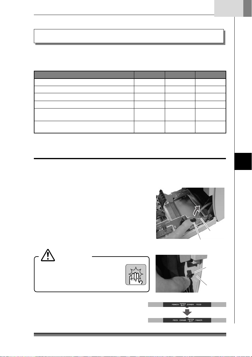
Clearing a Paper Jam
Clearing method
1.Turn off the power and open the rear
cover.
If the rear cover cannot be opened
When there is a cutter problem, the
printer may stop with the cutter blade
protruding so that pressing the FEED
switch fails to clear the error. When this
happens, restore the cutter blade
manually by inserting a screwdriver into
the hole on the left side surface of the
rear cover and rotating it, then open
the cover (the blade will be restored
whether you turn it to the left or right).
Turn the screw driver so that the
projections on both ends of the blade
of the cutter are returned to the back
of the printer (direction shown by the
arrow).
End of the blade of the cutter
Rear cover
Front cover
Paper cut bar
2.Remove all the jammed paper
(temporarily remove the roll paper
that is installed in the printer).
3.Close the rear cover and turn on the
power. The auto cutter operation will
be initialized and the error cleared.
Caution
When removing the jammed paper, be
careful not to touch the area around the
print head nor the cutter blade. If you
do you will be burned or cut.
42
Cutter lock clearing screw hole
Page 45

Trouble Shooting
When there is trouble with this printer, take action to clear up the trouble according
to the following table.
If this action does not clear up the trouble, notify the dealer where you purchased
the printer or service personnel.
Symptom Check Action
Paper jam
1
Rear cover
2
does not open
Check for a jam at the paper
ejection opening. If you cannot
open the rear cover, do check
number 2.
Check to see if the blade of the
auto cutter is protruding.
Remove all the jammed paper.
Remove the roll paper from the printer and put it
back again.
Insert a Phillips screwdriver (+) into the cutter
lock cancel use feed hole on the printer and turn
it clockwise or counter clockwise. (Use a #1
screwdriver.)
Rotate the screwdriver while watching the paper
ejection opening and stop turning it when both
ends of the blade are fully retracted. (→ P.42)
Caution
Do not try to force the rear cover to open. If
you do, the printer will be damaged and you
will be cut by the blade.
English
Maintenance Mode
Ribbon does
3
not feed
correctly
The paper is
4
not cut
Turn the knob on the ribbon
cassette.
Check to make sure that the
rear cover and front cover are
closed.
After turning the knob until the ribbon feeds
smoothly, reset the ribbon cassette.
If you cannot turn the knob, the ribbon may be
jammed inside the cassette. If the situation does
not improve, replace it with a new ribbon
cassette.
If one of the covers is open, close it. If the paper
still cannot be cut after you have closed the
cover, notify the dealer where you purchased the
printer or service personnel.
43
Page 46

Chapter5
Printing mode Serial impact dot matrix
Printing direction Bi-directional
Head pins 9 pins (φ: 0.3mm, Pin interval; 1/72inch)
Printing line columns
Font configuration 7Ω9 or 9Ω9 dots
Character types ASCII (96 characters), International characters, Katakana
Panel/switches 1 switch (FEED), 3 LED (POWER/PAPER OUT/ERROR), 1 buzzer
Printing speed Printing: 240CPS (3P paper 200CPS)
Paper feed Friction feed
Paper Types: 1P roll paper
Ribbon Method: special ribbon cassette
Interface Standard model: 2 models, either RS232C or IEEE1284
Emulation ESC/POS (Page mode)
Appendixes
Specifications
Paper width of 76.2mm 40/42 or 33/35 columns
Paper width of 69.5mm 36/40 or 30/32 columns
Paper width of 57.5mm 30/33 or 25/27 columns
200/400 dots (full dot/including half dot)
Code pages:
Through-put: 76.2mm wide, 40 columns (7Ω9+3sp, 6LPI) 5.0LPS
Minimum pitch: 1/144 inch
Paper feed speed: 40LPS (6LPI)
Paper widths: 76.2 / 69.5 / 57.5 (±0.5)mm
Roll diameter: φ30mm to φ83mm
Core diameter: Interior diameter φ10 mm, exterior diameter φ27mm or less
Paper thickness: 1P 0.06 to 0.085mm
* No glue on the core or end of the paper.
Colors: Single color (purple, black), 2 color (black and red)
Life: Purple, approx. 4 million characters (continuous printing at 25°C)
Black, approx. 3 million characters (continuous printing at 25°C)
Red/black, black 1.5 million characters, Red 750,000 characters
CBM mode, STAR mode
437, KATAKANA, 850, 860, 863, 865, 852, 866, 857, 858, WPC1252
69.5mm wide, 36 columns (7Ω9+3sp, 6LPI) 5.4LPS
57.5mm wide, 30 columns (7Ω9+3sp, 6LPI) 6.0LPS
2P copy roll paper (1 original + 1 copy)
3P copy roll paper (1 original + 2 copies)
* When 3P, printing speed falls 16%
+2
–0
Copy paper 0.05 to 0.20mm (total thickness)
But the total thickness that can be cut is from 0.05 to 0.14mm.
44
Page 47

English
Data buffer Receiving buffer: 40 or 4K bytes
NV bit image: 128K bytes
User NV memory: 8K
Features Paper-drop-in style
Auto cutter function (full cut/partial cut)
Rewinder function
Black mark sheet compatible
Copy (2P/3P) paper compatible
DKD (Drawer Kick Driver) function
ASB (Auto Status Back) function
Power CD-S500A type
Input: DC24V, 1.0A
CD-S500S type
Input: AC100V–240V, 0.55A–0.35A, 50/60 Hz
Power consumption: 24W
External dimensions Standard model: 156(W) x 247.7(D) Ω 132(H) mm
156 247.7
AC adapter and rewinder equipped model: 156(W) x 277.7(D) Ω 196.7(H) mm
132
156 277.7
Appendixes
196.7
45
Page 48

Chapter5
Specifications
Appendixes
Printer weight Standard model: 2.20kg
Environmental
conditions
Durability 7.5 million lines (MCBF)
Applicable standard UL, C-UL, FCC Class A, TÜV-GS, CE Marking, CCC
Auto cutter equipped model: 2.30kg
Auto cutter and rewinder equipped model: 2.45kg
But these exclude the AC adapter, AC case, ribbon, and paper.
During operation: Temperature 0 to 50°C
During storage : Temperature –20 to 70°C
90
50
Relative humidity (%)
10
Head lifetime 150 million characters
Cutter lifetime 1 million cuts
Humidity 10 to 90%RH (no condensation)
Humidity 5 to 90%RH (no condensation)
0 35 50
Environmental temperature (°C)
Ribbon Cassette
Cassette shape Single color specification, color (purple) : IR-31P
Two color specification, colors (red/black) : IR-31RB
Lifetime Single color specification, color (purple) : approx. 4 million characters
Two color specification, colors (red/black):
red approx. 750,000 characters/black approx. 1.5 million characters
Be sure to use a recommended ribbon cassette in order to maintain printing quality and
stabilize printer operation.
46
color (black) : IR-31B
color (black) : approx. 3 million characters
Page 49

English
Paper
Use the following printing paper in order to maintain printing quality and stabilize paper
feeding.
Roll paper Paper width: 76.2±0.7mm (3±1/36 inch)
Roll diameter: φ30mm to φ83mm
Core diameter: Interior diameter φ10 mm, exterior diameter φ27mm or less
Paper thickness: 0.06 to 0.085mm
Weight: 52.3 to 64.0 g/m
Recommended paper: Register paper (Oji Paper Co., Ltd.) or equivalent
Pressure sensitive
paper
Non-carbon 2P/3P paper, 1 original + 1 copy /2 copies
Paper width: 76.2±0.7mm (3±1/36 inch)
Roll diameter: φ30mm to φ83mm
Core diameter: Interior diameter φ10 mm, exterior diameter φ27mm or less
Paper thickness: 0.05 to 0.20mm
Recommended paper: 2P NCR Super (Mitsubishi Paper Mills Limited) (prints in blue)
69.5±0.6mm (3±1/36 inch)
57.5±0.5mm (2.26±0.02inch)
+2
–0
2
(45 to 55kg/1,000 sheets/788mm x 1,091mm)
69.5±0.6mm (3±1/36 inch)
57.5±0.5mm (2.26±0.02 inch)
But the total thickness that can be cut is from 0.05 to 0.14mm.
or equivalent
(JIS P8124)
+2
–0
Cautions concerning the roll paper
Starting to wind the roll paper (interior end) processing (with center core)
It must not be folded and its internal diameter must be even.
It must not be rolled back.
There must be no glue on its center core.
It must be wound with its printing side facing outwards.
When it is 2P paper, there must be no glue between the top and bottom sheets.
In the case of 3P paper, there must be no glue on the top, middle, or bottom papers.
Use pressure sensitive paper with total thickness no greater than 0.20mm and remember
that the printer will not cut paper with total thickness greater than 0.14mm.
If you use pressure sensitive paper with total thickness greater than 0.14mm, either do
not use the cutter or else rewind the bottom paper with the rewinder to reduce the
total thickness (top paper + middle paper) to 0.14mm or less.
Appendixes
47
Page 50

Chapter5
Appendixes
Interface
Serial (RS232C) interface
Pin assignment
PIN No. Signal Name Direction Function
1 Frame ground
2 TXD
3 RXD Input Data reception
4 RTS Output Same as DTR (20pin)
6 DSR Input Host reception enabled status HIGH-READY/LOW-NOT READY
7 Signal ground
20 DTR Output Printer READY/BUSY status HIGH-READY/LOW-BUSY
25 INIT Input Printer RESET (1ms or more is higher)
FG
SG
–
Output
–
Data transmission
[During DTR/RTS control]
The printer transmits data after it is confirmed that DSR is high.
(But transmission by DLE EOT, GS a)
[During XON/XOFF control]
Printer does not confirm DSR.
[During DTR/RTS control]
When the printer is in reception enabled status, it is READY, when it is
reception disabled, it is BUSY.
Printer status
1) BUSY until completion of initial settings when the power is turned on
2) BUSY in normal OFFLINE status
3) BUSY in OFFLINE status during PE
4) BUSY in OFFLINE status when other errors occur
5) BUSY when the reception buffer is full
6) BUSY during Self-Print
[During XON/XOFF control]
Always HIGH-READY except under the following conditions
1) Until completion of initial settings when the power is turned on
2) During Self-Print
Buffer Full Control
Reception buffer 40/4K
XON XOFF
Overrun/Buffer size: 16/512 bytes
XOFF cancel size: 8/1536 bytes
48
Connection with HOST
Printer D-Sub25P
1FG
2 TxD
3 RxD
20 DTR
6 DSR
16/512 bytes8/1536 bytes
4 RTS
5 CTS
7SG
25 RESET
Host D-Sub9P
1 DCD
3 TxD
2 RxD
4 DTR
6 DSR
7 RTS
8 CTS
5GD
9 RI/RESET
Page 51

Parallel (IEEE1284) Interface
Pin assignment
PIN No. Direction
Compatibility Mode
1 Input *Strobe HostCLK HostCLK
2 Input/Output Data0 Data0 Data0
3 Input/Output Data1 Data1 Data1
4 Input/Output Data2 Data2 Data2
5 Input/Output Data3 Data3 Data3
6 Input/Output Data4 Data4 Data4
7 Input/Output Data5 Data5 Data5
8 Input/Output Data6 Data6 Data6
9 Input/Output Data7 Data7 Data7
10 Output *ACK PtrCLK PtrCLK
11 Output BUSY PtrBUSY/Data3,7 PtrBUSY
12 Output PE AckDataReq/Data2,6 AckDataReq
13 Output SELECT Xflag/Data1,5 Xflag
14 Input *AutoFeed HostBUSY HostBUSY
15 – (NC) (ND) (ND)
16 – GND GND GND
17 – F G F G F G
18 Output Logic-H Logic-H Logic-H
19–30 – GND GND GND
31 Input *INIT *INIT *INIT
32 Output *FAULT *DataAvail/Data0,4 *DataAvail
33 – GND (ND) (ND)
34 Output DK_STATUS (ND) (ND)
35 Output +5V (ND) (ND)
36 Input *Select-in 1284-Active 1284-Active
Data Reception Timing
Function
Nibble Mode Byte Mode
(*: Active Low)
English
Appendixes
Data 1–8
∗STROBE
BUSY
∗ACK
A
C
B
D
EF
A : MIN. 1µs
B : MIN. 1µs
C : MIN. 1µs
D : MAX. 1µs
E : Approx. 3.2µs
F : Approx. 3.2µs
49
Page 52

Chapter5
Appendixes
Parallel (IEEE1284) Interface
Timing when power is on INIT signal timing
∗RESET
BUSY
∗INT
BUSY
A : More than 16µs
A
B : Less than 200µs
B
∗ACK
SELECT
∗ACK
∗FAULT
Drawer Kick-Out Interface
Pin assignment
PIN No. Direction Function
1 – Frame GND
2 Output Drawer Kick-out Signal 1
3 Input Drawer Open/Close
61
The ESC pm t1 t2 commands select either Drawer Kick-out Signal 1 or 2 to set the
pulse time.
Note:
• T2 (when OFF) ≥ T1 (when ON) Ω4 is satisfied.
• The maximum amperage at +24V is up to 1A. When connected to one that exceeds
1A, the printer and connected equipment may be damaged.
4 – +24V
5 Output Drawer Kick-out Signal 2
6 – Signal GND
T1 x 2ms
When ON
T2 x 2ms
When OFF
50
Page 53

FRANÇAIS
Page 54

Table des matières
ETAT DE CONFORMITÉ Á L’USAGE DES UTILISATEURS EUROPÉENS .............................. 3
CONSIGNES DE sécurité à observer impérativement! ........................................................... 4
Chapitre1 Introduction
Caractéristiques .................................................................................................... 8
Explication des différents modèles ................................................................... 9
Vérifier les accessoires ....................................................................................... 11
Chapitre2 Nom et fonction des différentes pièces
................................................................................................................................12
Chapitre3 Préparer l’imprimante
Raccordements.................................................................................................... 16
Installation............................................................................................................ 19
Réglage du capteur de l’approche de fin de rouleau de papier ............... 20
Installation de la cartouche de ruban............................................................. 21
Installation du rouleau de papier ....................................................................22
Chapitre4 Mode maintenance
Mode HEX Dump ........................................................................................... 29
Mode de réglage Soft SW ............................................................................ 29
Mode initial au départ de l’atelier ............................................................... 33
Mode de réglage de la position de coupe ................................................. 34
Indicateurs d’erreur ............................................................................................ 35
Dépannage ........................................................................................................... 37
Chapitre5 Annexes
Spécifications ...................................................................................................... 38
2
Page 55

Français
ETAT DE CONFORMITÉ À L’USAGE DES
UTILISATEURS EUROPÉENS
Le marquage CE indique la conformité aux critères et dispositions ci-dessous:
Directive basse tension (73/23/EEC)/EN60950-1
Directive sur la compatibilité électromagnétique (89/336/EEC)/EN55022,
EN55024, EN61000-3-2 & EN61000-3-3
Les noms de sociétés et de produits qui apparaissent dans ce manuel
sont des marques de fabrique, déposées ou non, des sociétés concernées.
Copyright © 2005 CITIZEN SYSTEMS JAPAN CO., LTD.
3
Page 56

CONSIGNES DE
sécurité à observer impérativement!
• Pour éviter tout dommage corporel ou matériel, les consignes ci-dessous
doivent impérativement être observées.
• La nature des dommages corporels ou matériels possibles à la suite d’une
utilisation incorrecte ou de la non-observation des consignes suivantes
est décrite ci-dessous.
Indique une situation qui, en cas de
Avertissement
Attention
comportement inadapté, risque d’entraîner
la mort ou des blessures graves.
Indique une situation qui, en cas de
comportement inadapté, risque d’entraîner
des blessures.
Signification des symboles
Ce symbole indique que quelque chose doit être manipulé
précautionneusement.
Ce symbole indique quelque chose qu’il ne faut pas faire.
Ce symbole indique quelque chose qu’il faut faire.
4
Page 57

Avertissement
Ne faites jamais tout ce qui est indiqué ci-dessous, cela risquerait
d’endommager l’imprimante, de la faire surchauffer, dégager de la fumée
et provoquer des brûlures ou un choc électrique. Si l’imprimante est
endommagée ou fonctionne mal, arrêtez-la immédiatement et retirez le
cordon d’alimentation. Consultez ensuite notre service après-vente.
• Ne placez pas l’imprimante dans un endroit mal aéré et ne fermez pas les
trous d’aération de l’imprimante.
• Ne placez pas l’imprimante à un endroit où se produisent des réactions
chimiques, par exemple dans un laboratoire ou à un endroit où l’air est mélangé
à du sel ou à du gaz.
• N’utilisez pas une fréquence électrique autre que celle qui est spécifiée.
• Ne branchez et ne débranchez pas le cordon d’alimentation ou le câble
d’interface en tirant sur le fil. Ne tirez pas et ne portez pas l’imprimante en
tendant le cordon d’alimentation ou le câble d’interface.
• Ne laissez tomber et ne mettez aucun objet étranger, tel une agrafe ou un
trombone, dans l’imprimante. Cela peut provoquer des problèmes.
• Ne branchez pas le cordon d’alimentation dans une prise qui alimente de
nombreux appareils.
• Ne déversez aucune boisson, telle du thé, du café ou du jus de fruit, sur
l’imprimante et ne vaporisez aucun insecticide dessus. Si vous versez
accidentellement de l’eau ou une autre boisson sur l’imprimante, mettez-la
immédiatement hors tension et débranchez le cordon d’alimentation, puis
consultez notre service après-vente.
• Ne démontez pas et ne modifiez pas l’imprimante.
• Lorsqu’un des interrupteurs de sécurité de l’imprimante a été désactivé,
n’utilisez pas l’imprimante sans résoudre le problème qui l’avait activé. Il y
aurait un risque de dysfonctionnement de l’imprimante, de blessures, de
brûlures ou d’électrocution.
Français
Jetez le sac d’emballage en plastique ou rangez-le en lieu sûr. Ce sac
doit être tenu hors de portée des enfants. Placé sur la tête, il peut
provoquer l’étouffement d’un enfant.
5
Page 58

Précautions générales
Attention
• Lisez attentivement les consignes de sécurité avant toute utilisation et
observez-les.
• Ne laissez tomber et ne mettez aucun objet étranger, tel une agrafe ou un
trombone, dans l’imprimante. Cela peut provoquer des problèmes.
• Faites attention quand vous déplacez ou transportez l’imprimante. Vous
pourriez vous blesser ou endommager quelque chose en la laissant tomber.
• En cas de chute accidentelle de l’imprimante, informez-en un technicien de
service après-vente. N’essayez pas de la réparer vous-même.
• N’ouvrez pas l’imprimante en cours d’impression.
• Ne nettoyez pas la surface extérieure de l’imprimante avec un chiffon imbibé
de solvant, de trichloréthylène, de benzène, de cétone ou de produits
chimiques similaires.
• N’utilisez pas l’imprimante à un endroit où l’on trouve beaucoup d’huile, de
particules de fer ou de poussière.
• Ne déversez pas de liquide et ne vaporisez pas d’insecticide sur l’imprimante.
• Ne soumettez l’imprimante à aucun choc ou impact en marchant dessus, en
la faisant tomber ou en frappant dessus.
• Utilisez correctement le panneau de commande. Une manipulation brusque
peut provoquer des problèmes ou un dysfonctionnement. N’utilisez pas d’outil
à bout pointu, comme un stylo bille par exemple, sur le panneau de commande.
• Faites attention aux bords des plaques, qui risqueraient de provoquer des
dommages corporels ou matériels.
• En cas de problème pendant l’impression, arrêtez immédiatement l’imprimante
et retirez le cordon d’alimentation de la prise.
• En cas de problèmes, n’essayez pas de démonter l’imprimante. Consultez
plutôt notre service après-vente.
6
Page 59
Français
Quelques précautions à observer lorsque vous installez votre imprimante
Attention
•
Lisez attentivement les consignes de sécurité avant toute utilisation et observez-les.
•
N’utilisez pas et n’entreposez pas l’imprimante à proximité d’un feu, d’une humidité
excessive, sous les rayons directs du soleil, à proximité d’une unité de climatisation
ou d’un chauffage ou encore d’une source d’humidité inhabituelle ou de poussière
excessive.
•
Ne placez pas l’imprimante à un endroit où se produisent des réactions chimiques,
par exemple dans un laboratoire.
•
Ne placez pas l’imprimante dans un endroit où l’air est mélangé à du sel ou à du gaz.
•
L’imprimante doit être installée sur une surface plane et solide permettant une
ventilation suffisante. Ne laissez jamais un objet obstruer les trous d’aération de
l’imprimante.
•
Ne posez rien sur l’imprimante.
•
Ne placez pas l’imprimante à proximité d’un poste de télévision ou de radio, et n’utilisez
pas pour l’imprimante la même prise électrique que pour la radio et la télévision.
Cela risquerait de nuire à la réception de votre téléviseur ou de votre poste de radio.
•
Ne placez rien sur le cordon d’alimentation et ne marchez pas dessus.
•
Ne tirez pas et ne portez pas l’imprimante lorsque le cordon d’alimentation et le
câble d’interface sont branchés.
•
Evitez de brancher le cordon d’alimentation dans une prise qui alimente de nombreux
appareils.
•
Ne pliez pas le cordon d’alimentation lorsque vous insérez la prise.
•
Pour brancher ou débrancher le cordon d’alimentation, prenez toujours la prise au
lieu de tirer sur le fil.
•
Vérifiez que l’imprimante est hors tension avant de brancher/débrancher le câble
d’interface.
•
Evitez d’utiliser le câble de signal avec une allonge ou de le brancher sur un appareil
qui fait du bruit. Si cela est indispensable, utilisez le câble métallisé ou une paire
torsadée pour chaque signal.
•
Placez l’imprimante à proximité d’une prise de façon à pourvoir retirer le câble et
couper l’alimentation électrique facilement.
•
Branchez l’imprimante sur une prise CA qui accepte une prise à trois broches, faute
de quoi de l’électricité statique pourrait se former avec les risques de choc électrique
que cela comporte.
•
Ne portez pas l’imprimante en tenant le capot. Ceci risquerait de casser ses
mécanismes ou de provoquer des dysfonctionnements.
7
Page 60

Chapitre 1
Introduction
Merci d’avoir acheté une imprimante matricielle à aiguilles Citizen CD-S500. Cette
imprimante matricielle à aiguilles a été conçue de façon à permettre son utilisation avec
différents types de terminaux de communication de données, de terminaux de point de
vente et d’imprimantes de cuisine.
Grâce aux nombreuses fonctions dont elle est dotée, elle peut être utilisée pour toute
une série d’applications.
Caractéristiques
Compacte
Mécanisme de chute du papier qui simplifie le chargement du papier
Impression grande vitesse jusqu’à 240 cps
Copie en plusieurs exemplaires (1 original + 2 copies)
Zone d’entrée
Mécanisme capteur de marques noires
Facilité d’adaptation de la mise en page de l’impression à l’aide du
mode page
Possibilité pour l’utilisateur d’enregistrer un logo ou du texte dans la
mémoire utilisateur
Interface intégrée de sortie du tiroir.
Coupe-papier automatique intégré (coupe complète ou partielle)
Fonctionne avec des papiers de différentes largeurs: 76,2/69,5/57,5
mm
Interface série (RS-232C) ou parallèle (conforme IEEE et Centronics)
prévue en atelier
Sélection de fonctions diversifiées par son panneau de commande
(mode de réglage Soft SW)
Peut se fixer au mur (en option)
Avertisseur sonore intégré
Adaptateur CA intégré ou externe
Impression en deux couleurs (rouge/noir)
8
Page 61

Explication des différents modèles
Les différents modèles de cette série sont identifiés de la façon indiquée ci-dessous:
Français
Numéro de modèle:
CD-S -
Nom du modèle
500 : modèle de base
1 : modèle avec coupe-papier
50
automatique intégré
503 : modèle avec coupe-papier
automatique et rembobineuse
intégrés
Type de source d’alimentation
A: adaptateur type CA
S: adaptateur type CA intégré
Interface
PA : compatible port parallèle IEEE1284
RS : compatible port série RS-232C
UB: USB
Région (caractères + cordon d’alimentation)
J : Japon
E : Europe
U : Amérique du Nord
C : Chine
-
Introduction
Coloris du boîtier
WH : Blanc
BK : Noir
Capteur de marques noires
None : pas de capteur
M1 : capteur gauche pour envers du papier
M2 : capteur droit pour envers du papier
M3 : capteur gauche pour la face d'impression du papier
M4 : capteur droit pour la face d'impression du papier
9
Page 62

Chapitre 1
Introduction
Explication des différents modèles
Exemples de modèles
Modèle de base
(type adaptateur CA)
CD-S500A--
Modèle à coupe-papier
automatique
(type adaptateur CA)
CD-S501A--
Modèle à coupe-papier
automatique et rembobineuse
(type adaptateur CA)
Modèle de base
(type adaptateur CA intégré)
CD-S500S--
Modèle à coupe-papier
automatique intégré
(type adaptateur CA intégré)
CD-S501S--
Modèle à coupe-papier automatique
et rembobineuse intégrés (type
adaptateur CA intégré)
10
CD-S503A-- CD-S503S--
Page 63

Vérifier les accessoires
Vérifiez que votre imprimante comporte bien les accessoires décrits ci-dessous.
Imprimante: 1
Adaptateur CA: 1
(série CD-S500A
uniquement)
Cordon d’alimentation: 1
Imprimante: 1
Type à adaptateur CA
Cartouche de ruban: 1
Séparateur: 1
Pieds en caoutchouc antidérapants: 4
(CD-S500S et CD-S501S uniquement)
Rouleau de papier: 1
Mode d’emploi (ce document)
Type à adaptateur CA intégré
Français
Introduction
* L’adaptateur CA est installé dans le
boîtier d’adaptateur CA
Adaptateur CA Cordon d’alimentation Cartouche de ruban
Séparateur Rouleau de papier Mode d'emploi (ce document)
11
Page 64
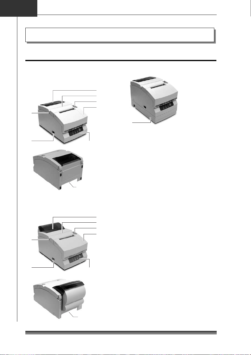
Chapitre 2
Extérieur
Nom et fonction des différentes pièces
Nom et fonction des différentes pièces
Type à adaptateur CA
Modèles de base et modèles à
coupe-papier automatique
1
2
3
6
5
Modèle à coupe-papier automatique
et rembobineuse
6
5
Panneau de commande
(voir page 14)
Connecteurs arrière
(voir page 15)
Panneau de commande
(voir page 14)
Connecteurs arrière
(voir page 15)
4
1
2
3
4
Type à adaptateur CA intégré
7
1 Fenêtre de contrôle du papier
Pour vérifier la quantité de papier qu’il
reste sur le rouleau.
2 Capot arrière
S’ouvre pour installer ou remplacer un
rouleau de papier.
3 Levier d’ouverture du capot arrière
Pour ouvrir le capot arrière. Tirez le levier
vers vous pour ouvrir le capot arrière.
4 Capot avant
S’ouvre pour installer ou remplacer une
cartouche de ruban.
5 Touche marche/arrêt
Pour mettre l’imprimante sous ou hors
tension.
6 Trou de la vis de déblocage de la lame
du coupe-papier
Lorsqu’il est impossible d’ouvrir le capot
arrière parce que la lame du coupe-papier
automatique dépasse en raison d’un
dysfonctionnement ou d’un bourrage
papier, tournez cette vis avec un tournevis
cruciforme pour faire revenir la lame.
7 Boîtier de l’adaptateur CA
Uniquement dans les modèles à
adaptateur CA intégré.
12
Page 65

Intérieur
Type à adaptateur CA
Modèles de base et modèles à
coupe-papier automatique
Français
8
6
Modèle à coupe-papier automatique
et rembobineuse
8
7
1
2
4
5
1
2
3
4
5
1 Unité du cylindre
Associé, sur les modèles de base et les
modèles à coupe-papier automatique,
avec le coupe-papier automatique 8.
2 Barre coupe-papier
Pour couper le papier manuellement.
3 Levier d’ouverture du cylindre
Pour ouvrir l’unité du cylindre sur les
modèles à rembobineuse automatique.
Tirez le levier vers vous pour ouvrir l’unité
du cylindre.
4 Capot de la tête d’impression
5 Arbre d’entraînement de la cartouche
de ruban
6 Tête d’impression
7 Axe de la rembobineuse
Rembobine la face copie du rouleau de
papier de copie.
8 Unité du coupe-papier
Coupe automatiquement le papier une
fois l’impression terminée. La coupe est
déclenchée par une commande du mode
de réglage Soft SW.
Nom et fonction des différentes pièces
6
13
Page 66

Chapitre 2
Nom et fonction des différentes pièces
Panneau de commande
5
123 4
1 Témoin d’alimentation (POWER) (vert)
S’allume lorsque l’imprimante est
alimentée en électricité. En mode
maintenance ou en cas d’indication
d’erreur, ce témoin est allumé ou clignote.
2 Témoin de sortie papier (PAPER OUT)
(orange)
S’allume en mode sortie papier. En mode
maintenance ou en cas d’indication
d’erreur, ce témoin est allumé ou clignote.
3 Voyant d’erreur (ERROR) (orange)
S’allume lorsque le capot arrière ou le
capot avant est ouvert. En mode
maintenance ou en cas d’indication
d’erreur, ce témoin est allumé ou clignote.
14
4 Touche d’avancée du papier (FEED)
Si vous appuyez une fois sur cette touche,
le papier avance (1 ligne). Si vous la tenez
enfoncée, le papier avance de façon
continue jusqu’à ce que vous relâchiez la
touche. En cas d’erreur de l’imprimante,
vous pouvez annuler le statut d’erreur en
appuyant sur cette touche.
5 LED d’information
Ce LED d’information peut être utilisé
dans l’autre sens en fonction de la
méthode d’installation de l’imprimante.
Voir la section consacrée à l’installation
verticale et murale (page 19).
Affichage en cas d’installation
horizontale
Affichage en cas d’installation
verticale et murale
Page 67

Connecteurs arrière
Français
Type à adaptateur CA
Interface parallèle (IEEE1284)
Interface série (RS232C)
123
Type à adaptateur CA intégré
4
1 Connecteur d’interface
Raccordé soit à un câble d’interface série (RS232C) soit à un câble d’interface parallèle
(IEEE1284).
* Une interface USB peut être remplacée par une interface série ou parallèle sur demande
en usine.
2 Connecteur d’arrêt du tiroir
Raccordé le câble du tiroir.
3 Connecteur de source d’alimentation
Raccordé au câble de l’adaptateur CA.
4 Arrivée du courant
Raccordée à un cordon d’alimentation.
Nom et fonction des différentes pièces
Autres
Avertisseur sonore intégré
Un avertisseur sonore se fait entendre lorsque vous appuyez sur la touche FEED et en cas
d’erreur. Il peut être activé ou désactivé en mode de réglage Soft SW.
Mémoire utilisateur
Le logo ou le texte saisis par l’utilisateur peuvent être stockés dans la mémoire, où ils
seront conservés même après une coupure de courant.
15
Page 68

Chapitre 3
Préparer l’imprimante
Raccordements
Raccordement du câble d’interface
Mettez l’imprimante hors tension et insérez les connecteurs en vérifiant qu’ils sont dans
le bon sens.
Attention
Lorsque vous retirez un câble, saisissez-le toujours par la prise.
Installez le câble d’interface de façon à ne pas vous prendre les pieds dedans, etc.
Raccordement du câble d’interface série (RS232C)
Veillez à insérer le câble fermement et à bien le fixer en serrant la vis.
Câble d’interface série (RS232C)
Raccordement du câble d’interface parallèle (IEEE1284)
Veillez à insérer le câble fermement et à bien le fixer à l’aide des crochets.
Câble d’interface parallèle (IEEE1284)
16
Page 69

Français
Raccordement du tiroir
Insérez le câble du tiroir dans le connecteur (RJ) d’interface du tiroir en faisant attention
à ce qu’ils soient dans le même sens et appuyez fermement jusqu’à ce que vous entendiez
un clic.
Câble d’arrêt du tiroir
Attention
Ne raccordez l’imprimante qu’à un tiroir spécialisé (pas à une ligne de téléphone).
Aucune sortie n’est possible pendant l’impression.
Le tiroir 1 et le tiroir 2 ne peuvent être actionnés simultanément.
Utilisez un solénoïde de tiroir d’au moins 24Ω. Veillez à ce que le courant de sortie
ne soit pas supérieur à 1A. Ceci risquerait en effet de provoquer des
dysfonctionnements ou des dommages par combustion.
Installez le câble d’arrêt du tiroir de façon à ce que vous ne risquiez pas de vous
prendre les pieds dedans, etc.
Préparer l’imprimante
17
Page 70

Chapitre 3
p
Préparer l’imprimante
Raccordement électrique
1.Assurez-vous que la touche marche/
arrêt de l’imprimante est sur OFF.
2.Si votre imprimante est une imprimante
de type adaptateur CA, insérez le
connecteur de l’adaptateur CA côté plat
sur le dessus dans le connecteur
d’alimentation situé sur la surface
arrière de l’imprimante.
Si votre imprimante est une
imprimante de type adaptateur CA
intégré, insérez la prise du cordon
d’alimentation dans l’arrivée CA
situé à l’arrière de l’imprimante.
Attention
N’utilisez pas un
adaptateur CA autre
que le modèle spécifié
(51 AD).
Lorsque vous débranchez le câble de
l’adaptateur CA, tirez-le toujours par le
connecteur.
En étirant le cordon d’alimentation, vous
risquez de l’endommager, de provoquer un
incendie, un choc électrique ou une
rupture du conducteur.
Si la foudre tombe à proximité, débranchez
le cordon d’alimentation de la prise
secteur. La foudre risque de provoquer un
incendie ou un choc électrique.
Ne placez pas le cordon d’alimentation à
proximité d’un appareil de chauffage. La
gaine du cordon pourrait fondre et
provoquer un incendie ou un choc
électrique.
Si l’imprimante ne doit pas être utilisée
pendant une période prolongée, veillez à
bien débrancher le cordon d’alimentation
de la prise secteur pour plus de sécurité.
Isolez la source de courant CA des autres
appareils qui génèrent du bruit.
DC 24V
51 AD
ONLY
Câble de l’adaptateur CA
Côté
lat du câble sur le dessus
Type à adaptateur CA
Arrivée CA
Type à adaptateur CA intégré
18
Page 71

Français
Ressort L du
cylindre du
châssis
Partie A
Installation
Votre imprimante peut être installée à l’horizontale ou à la verticale et peut être fixée au mur.
Cependant, en fonction du modèle que vous avez choisi, son installation peut faire l’objet de
restrictions. Reportez-vous au tableau ci-dessous.
Horizontalement
Modèle de base (type adaptateur CA) Oui Non Oui*
Modèle de base (type adaptateur CA intégré)
Modèle à coupe-papier automatique
(type adaptateur CA)
Modèle à coupe-papier automatique intégré
(type adaptateur CA intégré)
Modèle à coupe-papier automatique et
rembobineuse (type adaptateur CA)
Modèle à coupe-papier automatique et
rembobineuse intégrés (type adaptateur CA intégré)
*1: Les pieds en caoutchouc doivent être utilisés pour éviter que l’imprimante ne glisse.
*2: Le kit de fixation au mur spécialisé, livré en option, est nécessaire pour installer l’imprimante sur le mur.
Oui Oui*
Oui Non Oui*
Oui Oui*
Oui Non Non
Oui Non Non
Verticalement
1
1
Fixée au mur
2
2
Oui*
2
2
Oui*
Installation verticale et murale
Pour installer l’imprimante verticalement ou au mur, retirez le ressort L du châssis du cylindre
qui sert à ouvrir le capot arrière. Retournez ensuite le LED d’information sur le panneau de
commande pour utiliser l’imprimante avec le support vertical ou mural.
Retirer le ressort L du cylindre du châssis
1.
Ouvrez le capot arrière en procédant avec
précaution parce que l’ouverture est rapide.
2.
Soulevez la partie A avec les doigts de la main
droite.
3.
Passez le ressort L du cylindre du châssis que vous
avez soulevé de votre pouce droit à votre pouce
gauche afin d’accrocher la partie saillante à
l’extrémité de la partie B de l’imprimante.
Attention
Le ressort L du cylindre du châssis est
puissant. Veillez à ne pas le laisser vous
glisser des doigts, il pourrait vous blesser.
LED d’information
Retirez le LED d’information, retournez-le puis
réinsérez la pièce qui dépasse de son centre dans
l’imprimante et appuyez sur les deux extrémités.
Partie
saillante
Préparer l’imprimante
Partie B
19
Page 72

Chapitre 3
Préparer l’imprimante
Réglage du capteur de l’approche de fin de rouleau de papier
Changez le capteur de place en fonction de la façon dont l’imprimante est installée et du
diamètre intérieur du rouleau de papier que vous utilisez. En vous reportant au tableau
ci-dessous, réglez-le de façon adaptée à l’environnement d’utilisation en le déplaçant sur
la gauche et sur la droite tout en poussant la partie concave du centre du capteur avec
votre doigt. (au départ de l’usine, il est réglé sur un diamètre de 24 mm).
En cas
d’installation
à la verticale
ou au mur
Capteur de l’approche de fin de
6
5
4
En cas d’installation à l’horizontale
Méthode
d’installation
A l’horizontale
A la verticale
(fixée au mur)
rouleau de papier
3
2
1
Longueur de papier
restant sur le rouleau
(mm)
Approx. Ø22
Approx. Ø24
Approx. Ø27
Approx. Ø27
Approx. Ø24
Approx. Ø22
Emplacement du
capteur
1
2
3
4
5
6
Attention
La longueur restant de papier sur le rouleau (diamètre externe du rouleau de papier)
varie énormément en fonction du type de rouleau de papier utilisé. Ces valeurs ne
vous sont données qu’à titre indicatif.
Lorsque le capteur a détecté le reste de rouleau de papier pendant l’impression,
l’imprimante s’arrête d’imprimer après avoir imprimé toutes les données qu’elle a
reçues.
Si vous utilisez un modèle à interface parallèle (IEEE1284), vous pouvez choisir
d’activer ou de désactiver le capteur en mode de réglage Soft SW.
Si vous utilisez un modèle à interface série (RS232C), il est toujours activé.
20
Page 73

Installation de la cartouche de ruban
Français
.Ouvrez le capot avant de
1
l’imprimante.
Une main de chaque côté, passez vos
doigts dans les encoches situées de
part et d’autre du capot avant pour
l’ouvrir.
2.Tournez le bouton de la cartouche de
ruban dans le sens indiqué par la
flèche pour étirer complètement le
ruban.
3.Insérez la cartouche dans l’imprimante
et poussez-la jusqu’à ce que vous
entendiez un clic qui vous indique que
le ruban se trouve bien entre la barre
coupe-papier et le capot de la tête
d’impression. En cas de difficultés,
tournez à nouveau le bouton de la
cartouche de ruban.
Barre coupe-papier
Capot avant
Capot de la tête
d’impression
Préparer l’imprimante
4.Fermez le capot avant.
Attention
Faites très attention à ne pas toucher le
capot de la tête d’impression lorsque
vous remplacez la cartouche de ruban.
Lorsque la tête d’impression
est chaude, elle peut en effet
provoquer des brûlures.
21
Page 74

Chapitre 3
Préparer l’imprimante
Installation du rouleau de papier
Les types de rouleau indiqués ci-dessous peuvent être utilisés sur votre imprimante.
Types: rouleau de papier 1 P
rouleau de papier copie 2 P (1 original + 1 copie)
rouleau de papier copie 3 P (1 original + 2 copies)
(Il n’est possible d’utiliser des rouleaux de papier copie 2P et 3P que sur les
modèles équipés d’un coupe-papier automatique et d’une rembobineuse).
Largeurs de papier: 76,2 (± 0,7)/69,5 (± 0,6)/57,5 (± 0,5) mm
Diamètre des rouleaux: 30 à 83 mm
Diamètre du mandrin: diamètre intérieur 10 (0,+2 mm), diamètre extérieur 27 mm ou moins
Epaisseur du papier: 1P 0,06 à 0,085 mm
Papier copie 0,05 à 0,20 mm (épaisseur totale)
Mais l’épaisseur totale qui peut être coupée est comprise entre 0,05
et 0,14 mm.
Modèles standard et modèles à coupe-papier automatique
Méthode d’installation
1.Tirez le levier du capot arrière vers
vous pour ouvrir le capot arrière.
2.Mettez le séparateur fournie avec
l’imprimante en place si le rouleau de
papier que vous utilisez fait 69,5 ou
57,5 mm de large.
Modifiez la largeur du papier en
changeant la valeur définie comme
largeur à l’aide du mode de réglage
Soft SW (voir page 29).
Attention
Faites attention, en installant un
rouleau de papier, à ne
pas vous couper avec
les bords du papier.
Levier d’ouverture du capot arrière
Séparateur
Emplacement de la séparation pour un papier
Emplacement de la séparation pour un papier
de 69,5 mm de large
de 57,5 mm de large
22
Page 75
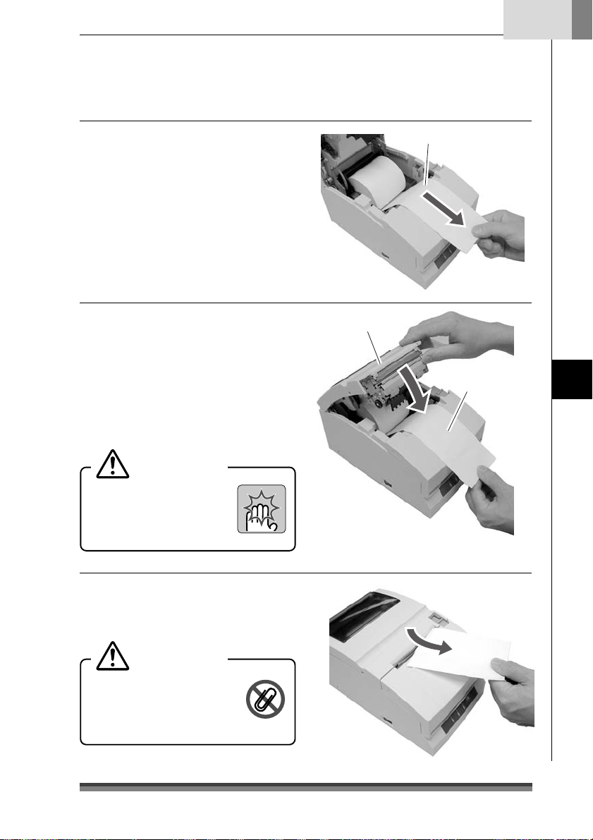
Français
3.Installez le rouleau de papier et tirez
un peu de papier vers vous comme
indiqué sur la photo.
Tenez le papier par le centre pour qu’il
reste aussi rectiligne que possible et
qu’aucun côté ne soit lâche.
4.Tout en maintenant le papier
légèrement tendu, fermez le capot
arrière en appuyant fermement
jusqu’à ce que vous entendiez un clic.
Le papier avance automatiquement et
s’arrête en position de démarrage de
l’impression.
Attention
Faites très attention à ne
pas vous coincer la main
dans le capot arrière en le
refermant.
Papier 1 P
Capot arrière
Papier légèrement
tendu
Préparer l’imprimante
5.Déchirez l’excédent de papier en le
tenant d’un côté et en tirant vers vous.
Attention
Ne laissez aucun objet
étranger, tel qu’un trombone
par exemple, glisser dans le
coupe-papier.
23
Page 76

Chapitre 3
Préparer l’imprimante
Installation du rouleau de papier
Modèles à coupe-papier automatique et rembobineuse
Méthode d’installation
1.Tirez le levier du capot arrière vers
vous pour ouvrir le capot arrière.
Levier d’ouverture du capot arrière
2.Tirez ensuite le levier d’ouverture du
cylindre pour ouvrir le module du
cylindre.
3.Mettez le séparateur fournie avec
l’imprimante en place si le rouleau de
papier que vous utilisez fait 69,5 ou
57,5 mm de large.
Modifiez la largueur du papier en
changeant la valeur définie comme
largeur à l’aide du mode de réglage
Soft SW (voir page 29).
Attention
Faites attention, en installant un
rouleau de papier, à ne
pas vous couper avec
les bords du papier.
Levier d’ouverture du cylindre
Unité du cylindreUnité du cylindre
Séparateur
Emplacement de la séparation pour un papier
Emplacement de la séparation pour un papier
de 69,5 mm de large
de 57,5 mm de large
24
Page 77

Français
4.Après avoir retiré l’axe de rembobinage,
installez le rouleau de papier de copie
et tirez l’extrémité du papier bien droit
vers vous sur environ 30 cm comme
indiqué sur la photo.
Tenez le papier par le centre pour qu’il
reste aussi rectiligne que possible et
qu’aucun côté ne soit lâche.
5.Tout en maintenant le papier
légèrement tendu, fermez le module
du cylindre en appuyant fermement
jusqu’à ce que vous entendiez un clic.
Attention
Faites très attention à ne
pas toucher la lame de la
barre coupe-papier.
6.
Placez un côté du papier de copie
(côté copie) sur l’arbre de la
rembobineuse comme indiqué sur la
photo et enroulez-le autour bien serré
(2 tours) dans le sens de la flèche.
Vérifiez que le rouleau de papier copie
tourne en même temps que l’arbre de
la rem bobineuse.
Arbre de la
rem bobineuse
Papier copie 2P ou 3P
Environ 30 cm
Unité du cylindre
Attention à la barre coupe-papier
Papier copie
(côté copie)
Dépasse
d’environ 5 cm
Papier légèrement
tendu
Préparer l’imprimante
Arbre de la
rem bobineuse
Enroulez-le en faisant deux tours
25
Page 78

Chapitre 3
Préparer l’imprimante
Installation du papier
7. En faisant bien attention à ne pas
laisser le papier copie placé sur l’arbre
de la rembobineuse se relâcher, placez
le papier dans les rainures de chaque
côté.
Tournez la molette de l’arbre de la
rem bobineuse dans le sens de la
flèche et vérifiez que le papier copie
s’enroule bien autour de l’arbre.
Tenez le papier tendu en vérifiant
qu’il s’enroule.
8.Tout en tenant l’autre côté du papier
copie (côté original) légèrement
tendu, fermez le capot arrière en
appuyant fermement jusqu’à ce que
vous entendiez un clic.
Tenez le papier par le centre pour qu’il
reste aussi rectiligne que possible et
qu’aucun côté ne soit lâche.
Le papier avance automatiquement et
s’arrête en position de démarrage de
l’impression.
Attention
Faites très attention à ne
pas vous coincer la main
dans le capot arrière en le
refermant.
Capot arrière
Papier légèrement
tendu
26
Page 79
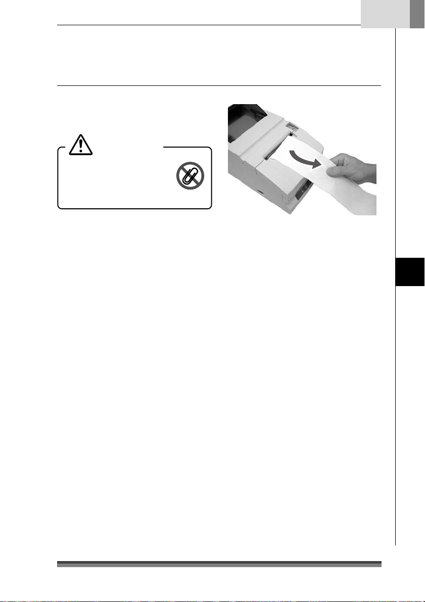
9.Déchirez l’excédent de papier en le
tenant d’un côté et en tirant vers vous.
Attention
Ne laissez aucun objet
étranger, tel qu’un trombone
par exemple, glisser dans le
coupe-papier.
Français
Préparer l’imprimante
27
Page 80
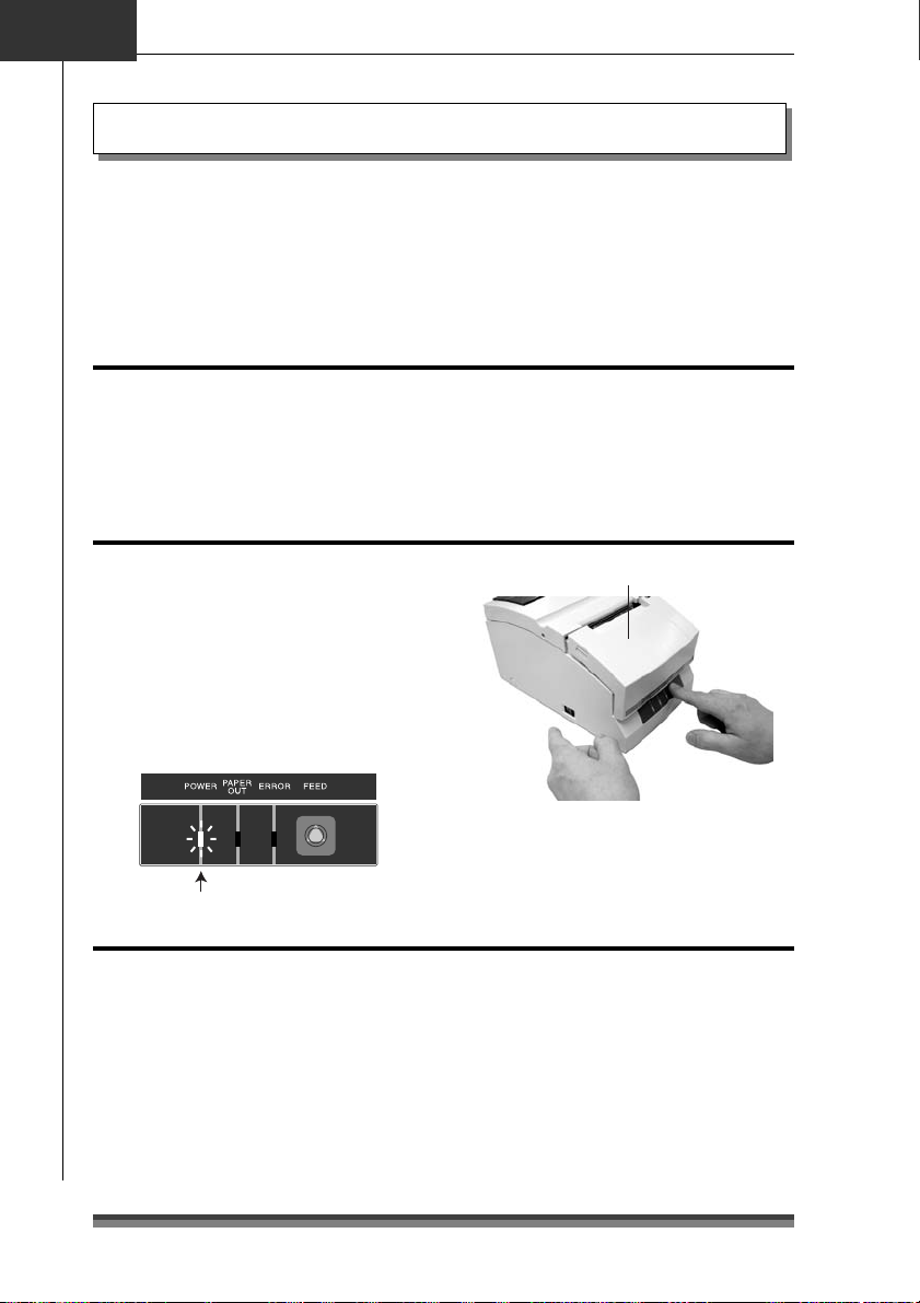
Chapitre 4
Mode maintenance
Mode maintenance
Le mode maintenance permet de modifier les paramètres de l’imprimante en fonction de
ses conditions d’utilisation. Il permet également de remettre ces paramètres en l’état
initial, tels qu’ils étaient à la sortie de l’atelier, ou de régler la position de coupe après
l’impression. Et les paramètres peuvent être confirmés en mode d’impression de
démonstration. Pour modifier les paramètres en mode maintenance, imprimez et vérifiez
les paramètres actuels de votre imprimante.
Mode d’impression de démonstration
Réglage du mode
Pour lancer le mode d’impression de démonstration, il suffit de mettre l’imprimante en
marche tout en appuyant sur la touche FEED alors que le capot avant et le capot arrière
sont tous les deux fermés. L’impression de démonstration et des paramètres d’impression
commence alors.
Passer en mode maintenance
1.Passez en mode maintenance en
mettant l’imprimante en marche tout en
appuyant une fois sur la touche FEED
alors que le capot avant est ouvert et le
capot arrière fermé.
2.Le témoin POWER se met à clignoter
lorsque l’imprimante passe en mode
maintenance. Fermez le capot avant.
Le témoin clignote
Touche
marche/arrêt
Capot avant ouvert
Touche FEED
Les différents types de mode maintenance
Ils sont au nombre de quatre.
Chaque mode peut être sélectionné en appuyant un certain nombre de fois sur la touche
FEED alors que l’imprimante est déjà en mode maintenance.
Mode HEX Dump
Mode de réglage Soft SW: appuyez sur la touche FEED 1 fois et ouvrez puis fermez le
capot avant.
Mode paramètres initiaux définis en atelier: appuyez sur la touche FEED 2 fois et ouvrez
puis fermez le capot avant.
Mode de réglage de la position de coupe: appuyez sur la touche FEED 3 fois et ouvrez
puis fermez le capot avant.
: appuyez sur la touche FEED 0 fois et ouvrez puis fermez le capot avant.
28
Page 81

Appuyez une fois
Le témoin clignote
Mode HEX Dump
Passez en mode HEX Dump
Si le capot avant est ouvert et fermé alors
que l’imprimante est en mode maintenance
(et que le témoin POWER clignote), le
témoin POWER s’arrête de clignoter et reste
allumé, et l’imprimante passe alors en mode
HEX Dump.
Après avoir imprimé le titre, elle reste en
attente des données.
Pour quitter le mode HEX Dump, arrêtez
l’imprimante et remettez-la en marche alors
que le capot avant et le capot arrière sont
tous les deux fermés.
Ouvrir et fermer le capot avant:
le témoin clignote puis s’arrête tout en
restant allumé
Le témoin clignote
Allumé
Français
Mode de réglage Soft SW
Passez en mode de réglage Soft SW
1.Si vous appuyez une fois sur la touche
FEED alors que l’imprimante est en
mode maintenance (et que le témoin
POWER clignote), les témoins POWER
et PAPER OUT se mettent à clignoter.
2.Si vous ouvrez puis fermez le capot
avant à ce moment, les témoins
POWER et PAPER OUT s’arrêtent de
clignoter et restent allumés. Après
avoir imprimé le titre et les rubriques,
l’imprimante passe alors en mode
réglage Soft SW.
de
Ouvrir et fermer le capot avant:
le témoin clignote puis s’arrête tout en
restant allumé
Le témoin clignote
Allumé
Mode maintenance
29
Page 82

Chapitre 4
Mode maintenance
Mode de réglage Soft SW
Mode d’utilisation
En appuyant sur la touche FEED (moins
de 2 secondes):
Le paramètre est modifié.
La valeur actuelle est modifiée et l’imprimante
réimprime la même rubrique. (appuyez sur
la touche FEED et relâchez-la lorsque
l’avertisseur sonore retentit une fois).
En tenant la touche FEED enfoncée (2
secondes ou plus):
Pour passer à la rubrique suivante.
Imprime la valeur actuelle de la rubrique
suivante. (appuyez sur la touche FEED et
relâchez-la lorsque l’avertisseur sonore
retentit trois fois).
Ouvrir/fermer le capot avant:
Après avoir enregistré les valeurs, réimprime
toutes les rubriques à partir du début et
repasse en mode marche normal.
* Si l’imprimante est arrêtée sans ouvrir et
fermer le capot avant, les changements
apportés aux paramètres sont invalides.
* Si le rouleau de papier finit pendant la
modification des paramètres, changez le
rouleau et fermez le capot arrière pour
poursuivre.
Fonctionnement
Appuyez sur
la touche FEED
Appuyez sur
la touche FEED
et maintenez-la
enfoncée
Appuyez sur
la touche FEED
et maintenez-la
enfoncée
<Soft-Switch Setting>
Press Feed
Change PARM.
Press Feed For 2S
Next Item
F.Cover Open/Close
Save & Exit
<Soft Control-SW>--------------------
Command Type —EPSON
Number of Col. —40/33
Font Select —7
Paper Plies —OFF
Paper End —ENB
Paper Near-End —ENB
Slashed Zero —OFF
Print Direct. —BI-DIR
Auto LF —OFF
Code Page —437
Buffer Size —4K
Init Signal —ENB
Buzzer —ON
<Interface-SW>------------------------
Baud Rate —9600
Data Length —8bit
Parity Bit —NONE
Stop Bit —1bit
Protocol —DTR
<Mechanical-SW>--------------------
Paper Width —76.2
Auto-Cutter —PAR.
Color Ribbon —ON
Take-Up Device —ON
Black Mark —DIS
Command Type —EPSON
Command Type —STAR
Number of Col. —40/33
Font Select —7
×
9
×
9
30
Appuyez sur
la touche FEED
Font Select —9
×
9
Exemple de passage du type de commande en
STAR et de la police sélectionnée en 9 x 9.
Page 83

Tableau des modes de réglage
Soft-Control SW
Rubrique Valeur initiale Valeurs possibles Observations
Command Type
(Type de commande)
Number of Col.
(Nombre de col.)
Font Select
(Police sélectionnée)
Paper Plies
(Plis de papier)
Paper End
(Fin de rouleau)
Paper Near-End
(Approche de fin
de rouleau de
papier)
Slashed Zero
(Zéro barré)
Print Direct BI-DIR BI-DIR
Auto LF OFF OFF
Code Page
(Page de codes)
EPSON EPSON
40/33 40/33
7x9 7Ω9
OFF OFF
ENB ENB
ENB ENB
OFF OFF
437
STAR
CBM1
CBM2
42/35
9Ω9
DIS
DIS
ON
UNI-DIR
ON
437
KATAKANA
850, 860
863, 865
852, 866
857, 858
WPC1252
L’émulation est sélectionnée entre EPSON/STAR/CBM1/
CBM2.
Le nombre de points complet dans une colonne pleine est
de 200. Pour le nombre de colonnes en fonction de la
largeur du papier.
La taille des caractères initiale est sélectionnée dès la
mise en marche de l’imprimante.
Le mode copie est sélectionnée.
2P
Vous pouvez sélectionner OFF/2P/3P, mais en 3P,
l’impression est lente.
3P
Le signal PE activé/désactivé est fixé à la fin du rouleau
quand seule la centro-interface est activée. En mode
activé, BUSY, PE et FAULT s’affichent et l’impression
s’arrête à la sortie du papier. En mode désactivé, rien
n’apparaît et l’impression s’arrête à la sortie du papier.
Le signal PE activé/désactivé est fixé à l’pproche de fin de
rouleau de papier, quand seule la centro-interface est
activée. En mode activé, BUSY et FAULT s’affichent et
l’impression continue. En mode désactivé, rien n’apparaît et
l’impression continue.
Pour définir si le chiffre zéro (0) est barré ou non.
Pour définir l’orientation de l’impression. Lorsque BI-DIR est
sélectionné, l’impression commence tout à gauche ou tout à
droite de la ligne d’impression qui suit l’endroit où
l’impression s’est arrêtée. En impression UNI-DIR,
l’impression se fait habituellement à partir du bord gauche.
Le fonctionnement en LF pendant la réception en code
CR est sélectionné. Sur ON, LF ne fonctionne pas. Sur
OFF, LF fonctionne.
CR: retour chariot LF: saut de ligne
La page de codes est sélectionnée.
Français
Mode maintenance
31
Page 84

Chapitre 4
Mode maintenance
Mode de réglage Soft SW
Rubrique Valeur initiale Valeurs possibles Observations
Buffer Size
(Taille de la mémoire)
Init Signal
(Signal init)
Buzzer
(Avertisseur sonore)
n
Interface-SW (s’affiche uniquement si la carte série est installée)
Rubrique Valeur initiale
Baud Rate
(Débit en bauds)
Data Length
(Longueur des
données)
Parity Bit
(Bit de parité)
Stop Bit
(Bit d’arrêt)
Protocol (Protocole)
n
Mechanical-SW
Rubrique Valeur initiale Valeurs possibles Observations
Paper Width
(Largeur du papier)
Auto-Cutter
(Coupe-papier
automatique)
Color Ribbon
(Couleur du ruban)
Take-Up Device
(Mécanisme
d’entraînement)
4k 40 octets
40 kilo-octets
ENB ENB
DIS
ON ON
OFF
Valeurs possibles
9600 19200
9600
4800
2400
1200
8 bit 8 bit
7 bit
NONE NONE
EVEN
ODD
1 bit 1 bit
2 bit
DTR DTR
X-ON-OFF
76.2 76.2
69.5
57.5
PAR. OFF
FREE
FULL
PAR.
ON ON
OFF
ON ON
OFF
La taille de la mémoire de réception est sélectionnée.
Pour activer (ENB) / désactiver (DIS) le signal initialisé
(PRIME) de l’imprimante pendant la centro-interface.
Pour activer (ENB) / désactiver (DIS) le signal de
réinitialisation 25pin pendant l’interface de série.
Pour activer (ON) / désactiver (OFF) l’avertisseur sonore
en cas d’anomalie.
Observations
Pour régler le débit en bauds de l’interface série.
Pour régler la longueur des caractères de l’interface série.
Pour régler la parité de communication de l’interface
série.
Pour régler le bit d’arrêt de l’interface série.
Sélectionne les dimensions du papier.
Pour sélectionner le fonctionnement du coupe-papier.
Lorsqu’il est sur OFF, les commandes FULL/PAR. ne
lancent pas la coupe.
En état FREE, la coupe se fait en fonction des commandes
FULL/PAR.
En état FULL, la coupe totale se fait toujours avec les
commandes FULL/PAR.
En statut PAR, la coupe partielle se fait toujours avec les
commandes FULL/PAR.
Pour sélectionner la fonction couleur.
En OFF, les commandes de changement de couleur sont ignorées.
Pour sélectionner la fonction de rembobineuse.
En OFF, le moteur de la rem bobineuse ne fonctionne pas.
32
Page 85

Rubrique Valeur initiale Valeurs possibles Observations
Black Mark
(Marque noire)
DIS DIS
TYPE1
TYPE2
Sélectionne activé (TYPE1, TYPE2) / désactivé (DIS) sur la
fonction de contrôle des marques noires.
Dans le statut TYPE1, l’opération automatique de mesure de
longueur du papier a lieu et la marque noire est placée au
niveau de la réglette d’imprimante lorsque l’appareil est allumé.
Les commandes GS FF/FF sont disponibles avec ce statut.
Il est utilisé pour formater la marque noire sur le bord de la
page.
Dans le statut TYPE2, l’opération de mesure n’a pas lieu
lorsque l’appareil est allumé.
L’opération automatique de mesure de longueur du papier, le
positionnement de départ du papier et les opérations de
découpage du papier sont contrôlées par la commande à
partir d’un PC hôte.
Seule la commande FS(L est disponible dans ce statut.
Il est utilisé pour formater la marque noire au milieu de
la page.
(Le statut TYPE2 n'est pas disponible en mode STAR ni en
mode CBM1/2.)
En ce qui concerne le fonctionnement en Mechanical SW
Les fonctions qui ne figurent pas dans les spécifications au moment de la livraison n’ont
aucun impact sur le fonctionnement de l’imprimante même quand les paramètres sont modifiés.
Exemples) Les rubriques réglées pour le coupe-papier automatique dans les modèles qui ne
sont pas équipés d’un coupe-papier automatique.
Modification du réglage du mécanisme d’appel du papier sur les modèles auxquels
les spécifications concernant la rembobineuse ne s’appliquent pas.
Français
Mode maintenance
En ce qui concerne le fonctionnement du coupe-papier automatique
L’intervalle minimum entre deux coupes est de 1,27 cm (3 lignes en 6 LPI).
Dès lors qu’une commande de coupe a été exécutée, même si une commande est
envoyée avant que le papier ait avancé d’au moins 1,27 cm, la commande de coupe
est ignorée et la coupe ne peut être exécutée.
Mode initial au départ de l’atelier
Passer en mode initial au départ de l’atelier
1.Appuyez deux fois sur la touche FEED
quand l’imprimante est en mode
maintenance (le témoin POWER
clignote). Les témoins POWER, PAPER
OUT et ERROR se mettent à clignoter.
Le témoin clignote
Appuyez deux
fois sur cette touche
33
Page 86

Chapitre 4
Appuyez trois fois
sur cette touche
Le témoin clignote
Mode maintenance
2.Ouvrez et fermez le capot avant.
Les témoins POWER, PAPER OUT et
ERROR s’arrêtent de clignoter mais
restent allumés.
3.
Maintenez la touche FEED enfoncée
pendant 3 secondes ou plus.
L’imprimante revient alors aux
paramètres définis au départ de l’atelier.
Mode de réglage de la position de coupe
Pour passer en mode de réglage de la position de coupe
1.Appuyez trois fois sur la touche FEED
quand l’imprimante est en mode
maintenance (le témoin POWER
clignote). Les témoins POWER et
ERROR se mettent à clignoter.
2.Ouvrez et fermez le capot avant. Les
témoins POWER et ERROR s’arrêtent
de clignoter mais restent allumés.
L’imprimante est alors en mode de
réglage de la position de coupe.
Ouvrir et fermer le capot avant:
le témoin clignote puis s’arrête tout en
restant allumé
Le témoin clignote
Ouvrir et fermer le capot avant:
le témoin clignote puis s’arrête tout en
restant allumé
Le témoin clignote
Allumé
Allumé
Mode d’utilisation
En appuyant sur la touche FEED (pendant
moins de 2 secondes):
La valeur est modifiée par tranche de
±1/144.
Ouverture et fermeture du capot avant:
Le sens de réglage change. Dès que
l’imprimante est en mode de réglage, la
valeur change en augmentant. Si vous
ouvrez puis refermez le capot avant, la
valeur ira en diminuant.
34
En maintenant la touche FEED enfoncée
(pendant 2 secondes ou plus):
La valeur est enregistrée et l’imprimante
passe en mode normal.
Modification du coupe-papier˚: +000
Position de coupe
Fourchette de réglage: – 035 à + 035
Valeur initiale: +000
Sens
d’avancée
du papier
Page 87

Français
Indicateurs d’erreur
En cas de dysfonctionnement de votre imprimante ou de bourrage papier, etc., le type de
problème est indiqué par un avertisseur sonore et par un témoin qui s’allume ou qui
clignote sur le panneau de commande.
En mode erreur, l’indication d’erreur peut être annulée en appuyant sur la touche FEED.
Tableau des indicateurs d’erreur
Type d’erreur Témoin Méthode de dépannage
Fin du rouleau POWER Allumé
Approche de fin
de rouleau de
papier
Capot avant/
arrière ouvert
Surchauffe de la
tête
HP anormal POWER
Marque noire
anormale
Détection d’une
position anormale
du coupe-papier
Anomalie matérielle
RAM lecture-écriture
Anomalie matérielle
FROM lectureécriture
24V anormal POWER Off
PAPER OUT Allumé
ERROR Off
POWER Allumé
PAPER OUT
ERROR Off
POWER Allumé
PAPER OUT
ERROR Allumé
POWER Allumé
PAPER OUT
ERROR
PAPER OUT
ERROR
POWER
PAPER OUT
ERROR
POWER
PAPER OUT
ERROR
POWER Off
PAPER OUT
ERROR
POWER Off
PAPER OUT
ERROR
PAPER OUT Off
ERROR
En fonction du statut
En fonction du statut
Pendant l’impression, l’impression s’arrête et
l’imprimante s’éteint. Remplacez le papier et fermez le
capot pour remettre l’imprimante sous tension.
En centro-interface, lorsque la fonction approche de fin
de rouleau de papier du mode Soft SW est activée, PE,
FAULT sont indiqués et l’impression continue. Si vous la
désactivez, rien ne s’affiche et l’impression continue.
Pendant l’impression, l’impression s’arrête d’un seul
coup et l’imprimante s’éteint. Fermez le capot pour la
remettre en route.
Le refroidissement commence. Une fois que la
température a baissé, l’imprimante redémarre
automatiquement et recommence à imprimer.
Le signal sonore continue de retentir jusqu’à ce que
l’erreur soit annulée par une pression sur la touche FEED.
L’imprimante s’éteint. Eliminez le bourrage papier ou
tout autre problème et appuyez sur la touche FEED
pour remettre l’imprimante en route.
Le signal sonore continue de retentir jusqu’à ce que
l’erreur soit annulée par une pression sur la touche
FEED.
Eteignez l’imprimante et remettez-la en marche. Si
l’erreur persiste, consultez le revendeur auquel vous
avez acheté l’imprimante ou notre personnel SAV après
avoir coupé l’alimentation électrique.
Mode maintenance
• Il n’y a pas d’indicateur d’erreur de communication RS232C ni d’indicateur de détection
d’ouverture ou de fermeture du capot avant.
• Si l’avertisseur sonore est sur OFF en mode Soft SW, il ne retentit pas.
: Allumé, : Off
35
Page 88

Chapitre 4
Mode maintenance
Elimination d’un bourrage papier
Méthode
1.Eteignez l’imprimante et ouvrez le
capot arrière.
Si vous ne parvenez pas à ouvrir le
capot arrière
S’il y a un problème avec le coupe-papier,
l’imprimante risque de s’arrêter alors que
la lame du coupe-papier dépassera, et
vous ne parviendrez pas à supprimer
l’erreur en appuyant sur la touche FEED.
Si cela arrive, remettez la lame du coupepapier en place manuellement en glissant
un tournevis dans la fente située sur le
côté gauche de la surface du capot arrière
et en le faisant tourner. Ouvrez ensuite le
capot (la lame reviendra à sa place que
vous tourniez le tournevis vers la gauche
ou vers la droite). Tournez le tournevis
de façon à ce que les projections des deux
extrémités de la lame soient entraînées
vers l’arrière de l’imprimante (sens de la
flèche).
Extrémité de la lame du coupe-papier
Capot arrière
Capot avant
Barre coupe-papier
2.Retirez tout le surplus de papier
(pour cela, retirez provisoirement le
rouleau de papier qui est installé
dans l’imprimante).
3.Fermez le capot arrière et mettez
l’imprimante en marche. Le coupepapier automatique est initialisé et
l’erreur résolue.
Attention
Lorsque vous éliminez un bourrage papier,
faites attention à ne pas toucher la zone
de la tête d’impression ou la lame du
coupe-papier. Vous risqueriez de vous
brûler ou de vous couper.
36
Trou de la vis de déblocage
de la lame du coupe-papier
Page 89

Dépannage
S’il survient un problème, suivez les indications du tableau ci-dessous pour le faire
disparaître.
En cas d’échec, consultez le revendeur auquel vous avez acheté l’imprimante ou notre
personnel SAV.
Symptôme Contrôle Action
Bourrage papier
1
Le capot arrière
2
ne s’ouvre pas.
Regardez si le bourrage se situe
à l’ouverture d’éjection du
papier. Si vous ne parvenez pas
à ouvrir le capot arrière, passez
au point n°2.
Vérifiez que la lame du coupepapier ne dépasse pas.
Retirez tout l’excédent de papier.
Retirez le rouleau de papier de l’imprimante et
remettez-le en place.
Glissez un tournevis cruciforme dans le trou de
déblocage et tournez-le dans le sens des aiguilles
d’une montre ou dans le sens inverse des aiguilles
d’une montre. (Utilisez pour cela un tournevis n°1).
Faites tourner la vis tout en surveillant l’ouverture
d’éjection du papier et en arrêtant de tourner dès
que les deux extrémités de la lame sont
complètement rétractées (→ p. 36).
Attention
Ne forcez pas si vous ne parvenez pas à ouvrir
le capot arrière. Cela endommagerait
l’imprimante et vous risqueriez de vous
couper avec la lame.
Français
Mode maintenance
3
Le ruban ne se
charge pas
correctement
4
Le papier n’est
pas coupé
Tournez le bouton situé sur la
cartouche de ruban.
Vérifiez que le capot arrière et
le capot avant sont fermés.
Après avoir tourné le bouton jusqu’à ce que le
ruban avance de façon régulière, remettez la
cartouche en place. Si vous ne parvenez pas à
tournez le bouton, cela peut signifier que le ruban
a provoqué un bourrage à l’intérieur de la
cartouche. Si la situation ne s’arrange pas,
installez une cartouche neuve à la place.
Si l’un des capots est ouvert, fermez-le. Si le
papier n’est toujours pas coupé après ça,
consultez le revendeur auquel vous avez acheté
l’imprimante ou notre personnel SAV.
37
Page 90

Chapitre 5
Mode d’impression: Imprimante matricielle à aiguilles à port série
Sens de l’impression Bidirectionnel
Aiguilles de la tête 9 aiguilles (φ: 0,3 mm), Intervalle des aiguilles: 1/72 pouce)
Colonnes de lignes
d’impression
Configuration de la police
Types de caractères ASCII (96 caractères), caractères internationaux, Katakana
Panneau de
commande / touches
Vitesse d’impression Impression : 240 CPS (papier 3 épaisseurs 200 CPS)
Entraînement
du papier
Papier Types : rouleau de papier 1 P
Ruban Méthode : cartouche à ruban spéciale
Interface Modèle standard: RS232C ou IEEE1284
Emulation ESC/POS (mode page)
Annexes
Spécifications
Largeur du papier : 76,2 mm 40/42 ou 33/35 colonnes
Largeur du papier: 69,5 mm 36/40 ou 30/32 colonnes
Largeur du papier: 57,5 mm 30/33 ou 25/27 colonnes
200/400 points (points complets/points partiels compris)
7 Ω 9 ou 9 Ω 9 points
Pages de codes 437, KATAKANA, 850, 860, 863, 865, 852, 866, 857, 858,
1 touche (FEED), 3 témoins (POWER/PAPER OUT/ERROR), 1 avertisseur sonore
Débit : 76,2 mm de large, 40 colonnes (7 Ω 9 + 3sp, 6 LPI) 5,0 LPS
Entraînement par friction
Pas minimal: 1/144 pouce
Vitesse d’entraînement du papier: 40 LPS (6 LPI)
Largeurs de papier : 76,2/69,5/57,5 (± 0,5) mm
Diamètre des rouleaux
Diamètre du mandrin :diamètre intérieur 10 (0,+2 mm), diamètre extérieur 27 mm ou moins
Epaisseur du papier : 1P 0,06 à 0,085 mm
* Pas de colle sur le mandrin ou à la fin du rouleau.
Couleurs : une seule couleur (pourpre, noir), 2 couleurs (noir et rouge)
Durée de vie
Mode CBM, mode STAR
WPC1252
69,5 mm de large, 36 colonnes (7 Ω 9 + 3sp, 6 LPI) 5,4 LPS
57,5 mm de large, 30 colonnes (7 Ω 9 + 3sp, 6 LPI) 6,0 LPS
rouleau de papier copie 2 P (1 original + 1 copie)
rouleau de papier copie 3 P (1 original + 2 copies)
* Avec du papier 3 P, la vitesse d’impression diminue de 16 %.
: 30 à 83 mm
Papier copie 0,05 à 0,20 mm (épaisseur totale)
Mais l’épaisseur totale qui peut être coupée est comprise entre
0,05 et 0,14 mm.
: Pourpre, environ 4 millions de caractères (impression continue à 25°C)
Noir, environ 3 millions de caractères (impression continue à 25°C)
Rouge/noir, noir 1,5 million de caractères, rouge 750000 caractères
38
Page 91
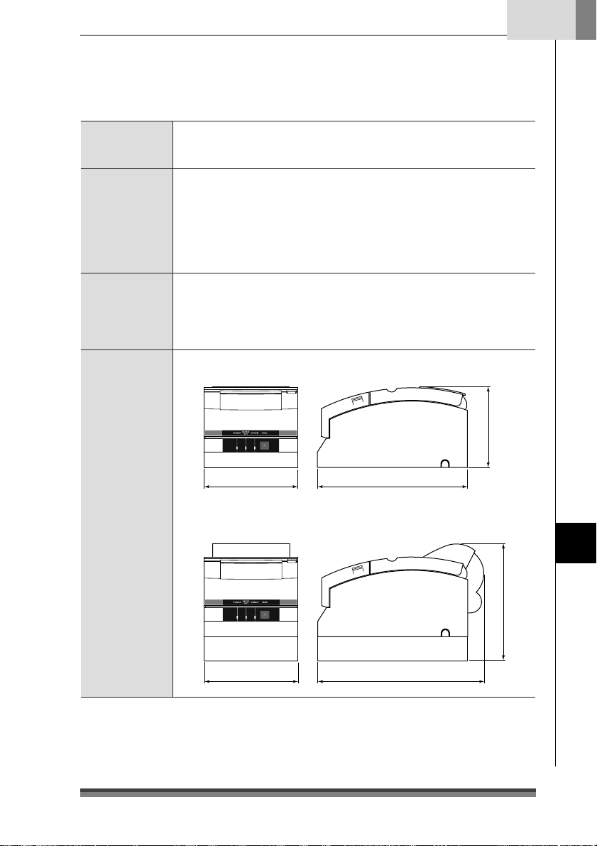
Français
Mémoire données Mémoire de réception : 40 octets ou 40 kilo-octets
Caractéristiques Chargement automatique du papier
Alimentation Type CD-S500A
Dimensions
extérieures
Image bit NV : 128 kilo-octets
Mémoire NV utilisateur : 8 k
Fonction coupe-papier automatique (coupe totale ou partielle)
Fonction de rembobinage
Compatible avec les feuilles à marques noires
Compatible avec le papier copie (2 ou 3 plis)
Fonction d’ouverture du tiroir-caisse
Fonction ASB (Auto Status Back)
Entrée: CD 24V, 1,0 A
Type CD-S500S
Entrée : CA 100V–240V, 0,55 A – 0,35 A, 50/60 Hz
Consommation électrique: 24 W
Modèle standard: 156 (L) x 247,7 (l) x 132 (H) mm
156 247,7
Modèles équipés d’un adaptateur CA et d’une rembobineuse :
156 (L) x 277,7 (l) x 196,7 (H) mm
132
156 277,7
Annexes
196,7
39
Page 92

Chapitre 5
Spécifications
Annexes
Poids de
l’imprimante
Conditions
ambiantes
Durabilité 7,5 millions de lignes (MCBF)
Normes applicables UL, C-UL, FCC Class A, TÜV-GS, Marquage CE, CCC
Modèle standard: 2,200 kg
Modèle à coupe-papier automatique: 2,300 kg
Modèle à coupe-papier automatique et rembobineuse: 2,450 kg
Sans l’adaptateur CA, le boîtier CA, le ruban et le papier.
En fonctionnement : Température 0 à 50°C
Pendant le stockage : Température – 20 à 70°C
90
50
Humidité relative (%)
10
Durée de vie de la tête d’impression: 150 millions de caractères
Durée de vie du coupe-papier: 1 million de coupes
Humidité 10 à 90% HR (sans condensation)
Humidité 5 à 90% HR (sans condensation)
0 35 50
Température ambiante (°C)
Cartouche de ruban
Forme de la
cartouche
Durée de vie Une seule couleur, couleur (pourpre) : env. 4 millions de caractères
Veillez à bien utiliser une cartouche de ruban recommandée afin de préserver la qualité
d’impression de votre imprimante et d’en stabiliser le fonctionnement.
40
Une seule couleur, couleur (pourpre) : IR-31P
couleur (noir) : IR-31B
Deux couleurs: couleurs (rouge/noir) : IR-31RB
couleur (noir) : env. 3 millions de caractères
Deux couleurs: couleurs (rouge/noir):
rouge env. 750000 caractères/noir env. 1,5 million de caractères
Page 93

Français
Papier
Utilisez le papier d’impression indiqué ci-dessous pour préserver la qualité d’impression
de votre imprimante et stabiliser l’entraînement du papier.
Rouleaux de papier Largeur du papier : 76,2 ± 0,7 mm (3 ± 1/36 pouce)
Diamètre des rouleaux
Diamètre du mandrin :
Epaisseur du papier : 0,06 à 0,085 mm
Poids : 52,3 à 64,0 g/m
Papier recommandé :
Papier autocopiant
Papier sans carbone 2 P/3 P, 1 original + 1/2 copies
Largeur du papier : 76,2 ± 0,7 mm (3 ± 1/36 pouce)
Diamètre des rouleaux
Diamètre du mandrin
Epaisseur du papier : 0,05 à 0,20 mm
Papier recommandé : 2P NCR Super (Mitsubishi Paper Mills Limited) (impression en
69,5 ± 0,6 mm (3 ± 1/36 pouce)
57,5 ± 0,5 mm (2,26 ± 0,02 pouce)
: 30 à 83 mm
diamètre intérieur 10 (0, +2 mm), diamètre extérieur 27 mm ou moins
2
(45 à 55 kg/1000 pages/788 mm x 1,091 m)
papier pour caisses enregistreuses (Oji Paper Co., Ltd) ou équivalent
69,5 ± 0,6 mm (3 ± 1/36 pouce)
57,5 ± 0,5 mm (2,26 ± 0,02 pouce)
: 30 à 83 mm
:
diamètre intérieur 10 (0, +2 mm), diamètre extérieur 27 mm ou moins
Mais l’épaisseur maximale de papier qui peut être coupée est de
0,05 à 0,14 mm
bleu) ou équivalent
(JIS P8124)
Précautions à observer en ce qui concerne les rouleaux de papier
Le papier s’enroule en partant de l’intérieur vers le centre.
Le papier ne doit pas être plié et son diamètre interne doit être le même partout.
Il ne doit pas être enroulé à l’envers.
Il ne doit pas y avoir de colle sur le mandrin.
Il doit être enroulé face imprimée à l’extérieur.
S’il s’agit de papier à 2 épaisseurs, il ne doit pas y avoir de colle entre les deux feuillets.
S’il s’agit de papier à 3 épaisseurs, il ne doit pas y avoir de colle entre les différents
feuillets.
Utilisez du papier autocopiant dont l’épaisseur totale ne dépasse pas 0,20 mm et
n’oubliez pas que l’imprimante ne peut couper le papier dont l’épaisseur est supérieure
à 0,14 mm.
Si vous utilisez du papier autocopiant dont l’épaisseur totale est supérieure à 0,14
mm, n’utilisez pas le coupe-papier ou alors enroulez le feuillet du bas avec la
rembobineuse pour réduire l’épaisseur totale (feuillet du haut + feuillet du milieu)
0,14 mm ou moins.
Annexes
41
Page 94

Page 95

DEUTSCH
Page 96

Inhalt
Konformitätserklärung für europäische Nutzer........................................................................................................ 3
Sicherheitshinweise, die unbedingt zu beachten sind! ........................................................................................... 4
Kapitel 1 Einleitung
Besondere Merkmale ................................................................................................................... 8
Erläuterung des Modells ............................................................................................................. 9
Überprüfung des Zubehörs auf Vollständigkeit ................................................................... 11
Kapitel 2 Bezeichnungen und Funktionen von Teilen
........................................................................................................................................................ 12
Kapitel 3 Vorbereitung des Druckers
Anschlüsse .................................................................................................................................... 16
Installation ................................................................................................................................... 19
Einstellung des Papierende-Sensors...................................................................................... 20
Installieren der Farbkassette ..................................................................................................... 21
Installieren von Papierrollen .................................................................................................... 22
Kapitel 4 Wartungsmodus
Hexdump-Modus (Modus mit hexadezimalem Speicherauszug) ................................ 29
Soft-SW-Einstellmodus ........................................................................................................ 29
Anfangsmodus bei Werksversand .......................................................................................33
Einstellmodus für die Schneideposition ........................................................................... 34
Fehleranzeigen ............................................................................................................................ 35
Fehlersuche/Problembehandlung........................................................................................... 37
Kapitel 5 Anhänge
Technische Angaben ................................................................................................................. 38
2
Page 97

Deutsch
Konformitätserklärung für europäische Nutzer
Das Zeichen CE zeigt an, dass das Gerät mit den folgenden Kriterien und Bestimmungen
übereinstimmt:
Niederspannungs-Direktive (73/23/EEC)/EN60950-1
EMC-Direktive (89/336/EEC)/EN55022, EN55024, EN61000-3-2 und EN61000-3-3
Maschinenlärminformations-Verordnung - 3. GPSGV, 06.01.2004:
Der höchste Schalldruckpegel beträgt 65 dB(A) oder weniger gemäß EN ISO 7779
Authorized representative in Europe :
Citizen Systems Europe GmbH
Mettinger Strasse 11
D-73728, Esslingen
Germany
Firmennamen und Produktnamen in der vorliegenden Bedienungsanleitung
sind Warenzeichen oder eingetragene Warenzeichen der jeweiligen Firmen.
Copyright C 2005 CITIZEN SYSTEMS JAPAN CO., LTD.
3
Page 98

Sicherheitshinweise,
die unbedingt zu beachten sind!
• Um Unfälle mit Verletzungen oder Sachschäden zu verhindern, sind die
folgenden Kennzeichnungen unbedingt zu beachten.
• Der Grad der möglichen Verletzungen oder Schäden aufgrund der falschen
Verwendung des Gerätes oder nicht befolgter Hinweise und Anweisungen sind
nachfolgend beschrieben.
Diese Kennzeichnung zeigt eine Situation an, die
bei Nichtbeachtung der gegebenen Hinweise und
Warnung
Vorsicht
Anweisungen sowie nicht richtiger Handhabung
zu einem ernsthaften oder sogar tödlichen Unfall
führen kann.
Diese Kennzeichnung zeigt eine Situation an, die
bei Nichtbeachtung der gegebenen Hinweise und
Anweisungen sowie nicht richtiger Handhabung
zu einem Unfall mit Verletzung führen kann.
Bedeutung von Symbolen
Dieses Symbol zeigt an, dass etwas mit besonderer Vorsicht gehandhabt
werden muss.
Dieses Symbol zeigt etwas an, was nicht getan werden darf.
Dieses Symbol zeigt etwas, was getan werden muss.
4
Page 99

Warnung
Die nachfolgend beschriebenen Dinge sind unbedingt zu unterlassen. Wenn dies
nicht beachtet wird, kann dies zu Schäden oder Problemen am Drucker führen,
ferner zu Überhitzungen und zur Freisetzung von Rauch oder schließlich auch zu
einem Brand oder einem elektrischen Schlag. Schalten Sie den Drucker unbedingt
sofort aus, wenn er beschädigt ist oder fehlerhaft funktioniert, und ziehen Sie dabei
auch unverzüglich den Stecker aus der Netzsteckdose. Wenden Sie sich dann an
unser Service-Personal.
•
Platzieren Sie den Drucker nicht an einem Ort mit unzureichender Ventilation und decken
Sie nicht die Lüftungsöffnungen des Druckers ab.
•
Platzieren Sie den Drucker nicht an Orten, an denen es chemische Reaktionen geben kann,
wie es beispielsweise in Labors der Fall ist, oder an Orten, an den die Luft mit Salzen oder
Gasen gemischt ist.
•
Schließen Sie den Drucker nicht an eine Stromquelle mit einer anderen Spannung oder
Frequenz als angegeben an.
•
Schließen Sie die Netzschnur nicht an und entfernen Sie sie nicht aus der Netzsteckdose,
indem Sie hastig daran ziehen. Das gilt auch für das Schnittstellenkabel, das Sie gleichfalls
nicht durch hastiges Ziehen anschließen/loslösen dürfen. Ziehen oder tragen Sie den
Drucker nicht, wenn dadurch die Zugkraft auf die Netzschnur oder das Schnittstellenkabel
erhöht wird.
•
Sorgen Sie dafür, dass keine Fremdkörper wie beispielsweise Büroklammern und Stifte in
den Drucker gelangen, denn das kann zu Problemen führen.
•
Schließen Sie die Netzschnur nicht an eine Steckdose mit vielen Stromabnehmern an.
•
Verschütten Sie keine Getränke wie beispielsweise Tee, Kaffee oder Saft auf dem Drucker
und sprühen Sie keine Insektizide auf den Drucker. Wenn ein Getränk oder Wasser verschüttet
worden ist, dann schalten Sie zuerst das Gerät ab und entfernen Sie die Netzschnur aus
der Steckdose, ehe Sie sich anschließend an unser Service-Personal wenden.
•
Demontieren oder modifizieren Sie den Drucker auf keinen Fall.
• Verwenden Sie den Drucker auf keinen Fall, wenn ein in das Gerät eingebauter
Sicherheitsschalter den Betrieb abgebrochen hat, ohne dass Sie das Problem gelöst haben,
das ihn aktiviert hat. Wenn Sie dies tun, besteht die Gefahr, dass der Drucker nicht richtig
funktioniert, dass er eine Verletzung oder einen Brand auslöst oder dass er Ihnen einen
elektrischen Schlag versetzt.
Entsorgen Sie den Folienbeutel, in dem das Gerät verpackt ist, oder bewahren Sie
ihn sicher auf. Dieser Beutel darf nicht in die Hände von Kindern gelangen. Wenn
Kinder sich den Beutel über den Kopf ziehen, können sie ersticken.
Deutsch
5
Page 100
Allgemeine Vorsichtsmaßregeln
Vorsicht
•
Lesen Sie die Sicherheitshinweise vor der Inbetriebnahme des Druckers aufmerksam und
befolgen Sie diese Hinweise.
•
Lassen Sie keine Fremdkörper wie beispielsweise Büroklammern und Stifte in den Drucker
fallen oder auf irgendeine Weise in den Drucker gelangen, denn dies kann zu Problemen
führen.
•
Lassen Sie bei der Fortbewegung oder dem Tragen des Druckers Vorsicht walten, denn
wenn der Drucker herunterfällt, kann dies zu einer Verletzung oder zu Sachschäden führen.
•
Wenn der Drucker versehentlich heruntergefallen ist, dann wenden Sie sich auf jeden Fall
an einen qualifizierten Service-Mitarbeiter. Versuchen Sie auf keinen Fall, den Drucker selbst
zu reparieren.
•
Öffnen Sie den Drucker keinesfalls während des Druckens.
•
Verwenden Sie, wenn Sie die Oberfläche des Druckergehäuses reinigen, auf keinen Fall ein
mit Verdünner, Trichloräthylen, Benzin, Keton oder ähnlichen Chemikalien getränktes Tuch.
•
Betreiben Sie den Drucker nicht an Orten, an denen viel Öl, Eisenpartikel oder Staub
vorhanden sind.
•
Verschütten Sie keine Flüssigkeiten auf dem Drucker und sprühen Sie keine Insektizide
darauf.
•
Rütteln Sie den Drucker nicht, versetzen Sie ihm keinen Stoß oder Schlag, treten Sie nicht
drauf und lassen Sie ihn nicht fallen.
•
Achten Sie auf einen korrekten Umgang mit dem Bedienfeld. Eine unvorsichtige und grobe
Handhabung kann zu Problemen oder Fehlfunktionen führen. Verwenden Sie kein
scharfkantiges Werkzeug wie beispielsweise einen Kugelschreiber für die Bedienung.
•
Achten Sie sorgfältig auf die Kanten der Abdeckung, um Verletzungen oder Sachschäden
zu vermeiden.
•
Wenn während des Druckvorgangs ein Problem auftritt, dann stoppen Sie den Drucker
unverzüglich und ziehen Sie sofort den Stecker aus der Netzsteckdose.
•
Wenn es zu Problemen mit dem Drucker kommt, dann versuchen Sie auf keinen Fall, ihn zu
zerlegen, sondern wenden Sie sich stattdessen an unser Service-Personal.
6
 Loading...