

User’s Manual
Mode d’emploi
Benutzerhandbuch
Manuale dell’utente
Manual del usuario

Declaration of Conformity
Manufacturer’s Name : Japan CBM Corporation
Manufacturer’s Address : CBM Bldg., 5-68-10, Nakano, Nakano-ku
Tokyo, 164-0001, Japan
Declare the Product
Product Name Line Thermal Printer
Model Number(s) CBM1000II Series
(CBM1000II RF/PF)
(S.No.0180001)
Conform to the following Standards
LVD : EN60950 :
EMC : EN55022 :
: EN61000-3-2 :
: EN61000-3-3 :
: EN55024 :
: EN61000-4-2 :
: EN61000-4-3 :
: EN61000-4-4 :
: EN61000-4-5 :
: EN61000-4-6 :
: EN61000-4-8 :
:
EN61000-4-11: 1994 10ms/95%, 500ms/30%, 5000ms/100%
Supplementary Information
“The product complies with the requirements of the Low Voltage Directive 73/
23/EEC, 93/68/EEC and the EMC Directive 89/336/EEC, 92/31/EEC, 93/68/EEC”
A11: 1997
1998 Class A
1995/A1/A2: 1998
1995
1998
1995 ±4KV CD, ±8 KV AD
1995 3 V/m, 80 MHz-1000 MHz AM 1 KHz 80 %
1995
±1.0 KV (AC Mains), ±0.5 KV (Signal Lines)
1995 1 KV Normal mode, 2 KV Common mode
1996 3 V, 0.15 MHz-80 MHz AM 1 KHz 80 %
1993 50 Hz, 3 A/m (Out of scope)
Place Tokyo, Japan Signature
Date August 2001
Full Name : Mikio Moriya
Position : General Manager
R & D Department
European Contact :
Norco Declaration AB
Box 7146 S-250 07 Helsingborg Sweden
Warning : This is a Class A product. In a domestic environment this product may cause radio
interference in which case the user may be required to take adequate measures.
This declaration is applied only for 230 V model.

IMPORTANT: This equipment generates, uses, and can radiate radio frequency
energy and if not installed and used in accordance with the instruction manual,
may cause interference to radio communications. It has been tested and found to
comply with the limits for a Class A computing device pursuant to Subpart J of
Part 15 of FCC Rules, which are designed to provide reasonable protection against
such interference when operated in a commercial environment. Operation of this
equipment in a residential area is likely to cause interference, in which case the
user at his own expense will be required to take whatever measures may be
necessary to correct the interference.
CAUTION: Use shielded cable for this equipment.
Sicherheitshinweis
Die Steckdose zum Anschluß dieses Druckers muß nahe dem Grät angebracht und
leicht zugänglich sein.
For Uses in Canada
This digital apparatus does not exceed the class A limits for radio noise emissions
from digital apparatus, as set out in the radio interference regulations of the
Canadian department of communications.
Pour L’utilisateurs Canadiens
Cet appareil numérique ne dépasse pas les limites de carégorie a pour les
émissions de bruit radio émanant d’appareils numériques, tel que prévu dans les
réglements sur l’interférence radio du départment Canadien des communications.

ENGLISH
ENGLISH
— 1 —

THE TABLE OF CONTENTS
1. GENERAL OUTLINE ............................................................................. 9
1.1 Features ..................................................................................................... 9
ENGLISH
1.2 Unpacking .................................................................................................. 9
2. BASIC SPECIFICATIONS .................................................................... 10
2.1 Model Classification ............................................................................... 10
2.2 Outer Appearance and Component Parts ............................................ 10
2.3 Basic Specifications ................................................................................ 11
2.4 Print Paper Specifications and Print Position ...................................... 12
2.5 Sensor Position and Cutter Position .....................................................13
3. OPERATION ........................................................................................ 14
3.1 Connecting the AC Adapter and AC Power Cord ................................ 14
3.2 Connecting Interface Cables .................................................................. 14
3.3 Connecting the Drawer Kick-Out Connector ........................................ 15
3.4 Setting/Replacing Paper Rolls ............................................................... 16
3.5 Adjusting the Paper Near-End Sensor .................................................. 16
3.6 Using 58 mm Wide Paper Rolls ............................................................. 17
3.7 Removing Jammed Paper ..................................................................... 17
3.8 Cleaning the Print Head ......................................................................... 17
3.9 Operation Panel and Error Indication ................................................... 18
3.10 Self-printing........................................................................................... 20
3.11 Hexadecimal Dump .............................................................................. 20
3.12 Printer Buffer .........................................................................................21
3.13 Device ID ................................................................................................ 21
4. SETTING DIP SWITCHES ................................................................... 22
4.1 Location of DIP Switches ....................................................................... 22
4.2 Table for Setting DIP Switches .............................................................. 22
5. MAINTENANCE AND SERVICE ......................................................... 24
APPENDIX 1. OUTLINE DRAWING .......................................................... i
APPENDIX 2. BLOCK DIAGRAM .............................................................. i
APPENDIX 3. IDENTIFICATION OF SEND STATUS ............................... ii
APPENDIX 4. PARALLEL INTERFACE .................................................... iii
APPENDIX 5. SERIAL INTERFACE .......................................................... v
APPENDIX 6. CONTROL COMMAND ................................................... vii
— 2 —

GENERAL PRECAUTIONS
1 The information contained herein is subject to change without prior notice.
2 All rights reserved. Reproduction of part or all of this document is prohibited
without written permission from CBM Corporation.
3 Except explained elsewhere in this manual, do not attempt to service,
disassemble or repair this product by yourself.
4 Note that CBM shall not be responsible for any damage attributable to
incorrect operation/handling or improper operating environments which are
not specified in this manual.
5 Operate this printer only as described in this manual. Failure to do so may
cause accidents or other problems.
6 Data are basically for temporary use, not stored for a long period or
permanently. Please note that CBM is not responsible for any damage or
lost profit resulting from the loss of data caused by accidents, repairs, tests,
or any other occurrence.
7 If you have any question or comment regarding the information contained
in this manual, please contact your CBM dealer.
8 Please note CBM is not responsible for anything that may occur from
operating this printer regardless of what is stated in “7” above.
ENGLISH
— 3 —
SAFETY PRECAUTIONS
Before using this product for the first time, carefully read these SAFETY
PRECAUTIONS. Incorrect operation may result in unexpected accidents (fire,
ENGLISH
shock, or injury).
● After having read this Manual, keep it in a safe, readily-accessible place for future
reference.
● Some of the descriptions contained in this manual may not be relevant to some
printer models.
In order to prevent injury hazard to operators, third parties or damage to
property, special warning symbols are used in this user’s manual to indicate
important items to be strictly observed.
● The following describes the degree of hazard and damage that could occur if the
printer is improperly operated by ignoring the instructions indicated by the
warning symbols.
WARNING
Neglecting precautions indicated by this symbol may result in fatal or serious
injury.
CAUTION
Neglecting precautions indicated by this symbol may result in injury or
damage to properties.
This symbol is used to alert your attention to important items.
This symbol is used to indicate prohibited actions.
This symbol is used to alert you to the danger of electric shock or
electrostatic damage.
This symbol denotes a request to unplug the printer from the wall
outlet.
— 4 —
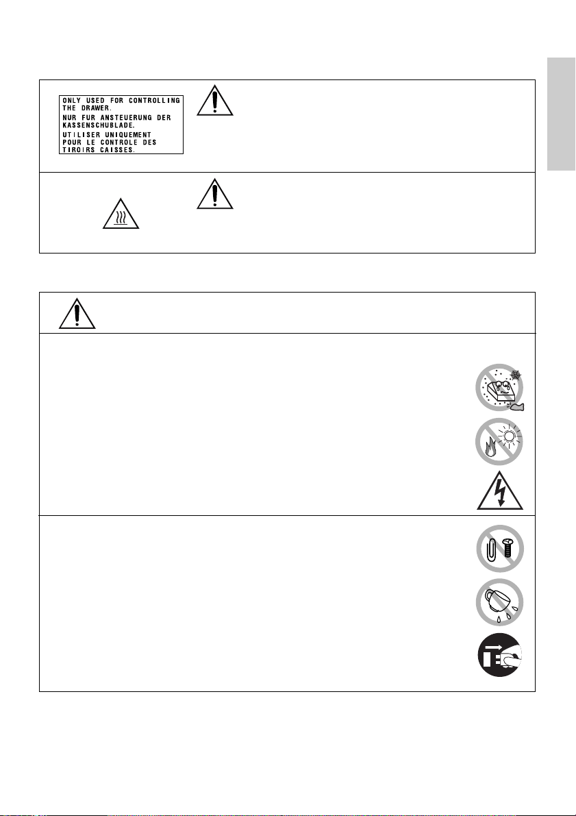
Caution Labels
WARNING
• Do not attempt to insert any plug (e.g. modular plug) other
than the specified drawer kick-out connector plug into the
drawer kick-out connector as it may damage the telephone
connection or the printer.
CAUTION
• The thermal head remains at a dangerously high
temperature immediately after use. Do not touch the head
until it cools off.
WARNING
Do not use or store this product in a place where it will be exposed to:
• Flames or moist air
• Direct sunlight
• Hot airflow or radiation from a heating device
• Ill-ventilated atmosphere
• Chemical reactions in a laboratory
• Airborne oil, steel particles, or dust
• Salty air or corrosive gases
• Static electricity or strong magnetic fields
●Neglecting these warnings may result in printer failure,
overheating, emission of smoke, fire, or electric shock.
ENGLISH
Do not drop any foreign object nor spill liquid into the printer. Do not
place any object on the printer either.
• Do not drop any metallic object such as a paper clip, pin or screw into
the printer.
• Do not place a flower base, pot or cup containing water on the
printer.
• Do not spill coffee, soft drinks or any other liquid into the printer.
• Do not spray insecticide or any other chemical liquid over the
printer.
●A metallic foreign object, if accidentally dropped into the printer,
may cause printer failure, fire, or electric shock. Should it occur,
immediately turn the printer off, unplug it from the supply outlet,
and call your local CBM dealer.
— 5 —

Please observe the following precautions for power source and power cord:
• Do not plug or unplug the power cord with a wet hand.
• Use the printer only at the specified supply voltage and
frequency.
• Use only the specified AC adapter with the printer.
ENGLISH
• Check to make sure that the supply outlet from which the
printer is powered has a sufficient capacity.
• Do not plug the power cord into a supply outlet with dust or debris left
on its plug.
• Do not supply the printer from a power strip or current tap shared with
other appliances.
• Do not use a deformed or damaged power cord.
●Neglecting to handle properly may result in printer failure,
emission of smoke, fire, or electric shock.
●An overload may cause the power cable to overheat or the circuit
breaker to trip.
• Do not allow anything to rest on the power cord. Do not place the
printer where the power cord will be trampled on.
• Do not attempt to modify the power cord unnecessarily.
• Do not use or carry the printer with its power cord bent, twisted, or
pulled.
• Do not lay the power cord in the neighbor of a heating device.
●Neglecting these cautions may cause wires or insulation to break, which
could result in leakage, electric shock, or printer failure. If a power cord
sustains damage contact your CBM dealer.
• Supply power to the printer from a convenient wall outlet,
readily accessible in an emergency.
• Do not leave things around the supply outlet to always
ensure easy access to it.
●The printer may not be immediately shut down in an
emergency.
• Insert the power plug fully into the outlet.
• If the printer is not to be used for a long time period, leave it
disconnected from its supply outlet.
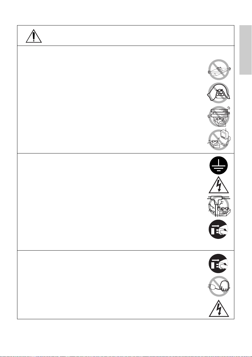
Do not handle the printer in the following ways:
• Do not allow the printer to sustain strong impacts or hard jolts (e.g.
trampling, dropping, striking with a hard edge).
• Never attempt to disassemble or modify the printer.
• Do not clean the printer with any organic solvent, such as
alcohol, paint thinner, trichloroethylene, benzene, or keton.
●Neglecting to handle properly may result in printer
Benzine
Thinner
failure, overheating, emission of smoke, fire, or electric
shock.
Install, use, or store the printer out of the reach of children.
●The plastic bag the printer came in must be disposed of properly or kept
away from children. Wearing it over the head may lead to suffocation.
●Electric appliances could cause an unexpected injury or accident if they
are handled or used improperly.
●Keep the power cord and signal cables out of the reach of children. Also
children should not be allowed to gain access to any internal part of the
printer.
— 6 —
CAUTION
Place the printer on a flat surface.
●Otherwise it may drop off from its position.
Be careful where you place the printer and what is placed near it.
• Take care that a nearby wall or some kind of cloth does not block
printer ventilation holes.
• Do not use the printer with any object placed on it.
●Be careful about internal heat buildup, which could cause fire and
deform the case.
• Avoid using the printer near a radio or TV set or from supplying it
from the same outlet as these appliances.
• For interconnections, use shielded or a twisted pair of cables and
ferrite cores, or other anti-noise devices.
• Avoid using the printer with a device that is a strong source of noise.
●The printer may have an adverse effect on nearby radio or TV
transmissions. There may also be cases when nearby electrical
appliances adversely influence the printer, causing data errors or
malfunction.
Use the printer with its grounding post connected to a convenient
grounding facility.
●If leakage occurs electric shock may result.
Do not connect the printer’s grounding post to any of the following
facilities:
• Utility gas piping
●A gas explosion could result
• Telephone line ground
• Lightning rod
●If lightening strikes a large surge of current may cause fire or
shock
• Utility water pipes
●Plastic water pipes should not be used for grounding. (Those
approved by a Waterworks Department may be used.)
Before connecting or disconnecting the grounding lead to or from the
printer, always unplug it from supply outlet.
Before connecting or disconnecting the power cord or interconnect
cables to or from the printer, always turn the entire system power off.
When disconnecting a cable, do not pull out by the cable. Always hold
the plug.
Firmly insert the cable plug into its mating socket.
●A cross connection may damage the printer’s internal electronics
or the host system’s hardware.
Only use the printer with devices that have designated solenoid
specifications for the drawer kick-out connector.
●Neglecting this caution may result in malfunction or failure.
ENGLISH
— 7 —

To prevent possible malfunction or failure observe the following:
• Avoid operating the printer without roll paper properly loaded or
with paper not complying with specifications.
●May damage thermal head or result in poor print quality.
ENGLISH
• Avoid using torn pieces of paper or spliced with plastic adhesive
tapes.
• Avoid forcibly pulling already loaded paper by hand.
• Avoid wedging the paper in by the printer cover.
●May jam paper. To release, refer to “Removing Jammed Paper”
in this manual.
• Avoid using a sharp pointed device to operate panel keys.
●Neglecting these cautions may result in printer malfunction or
failure.
To prevent injury and printer failures from worsening, observe the
following:
• In case of trouble do not attempt to repair the printer.
Leave it to our service engineer.
• Do not touch the printing surface of the thermal head.
• Be careful that the printer cover does not entrap your hands or
fingers.
• Be careful with sharp edges on the printer. Don’t allow them to injure
you or damage property.
• Do not touch any of the moving parts (e.g. paper cutter, gears, active
electrical parts) while the printer is working.
●May result in electric shock, burn, or injury.
●If the printer emits smoke, an odd smell, or unusual noise while
printing, immediately abort the current print session and unplug
the printer from the supply outlet.
DAILY MAINTENANCE
Observe the following precautions for daily maintenance:
• When cleaning the printer, always turn it off and unplug it from the
supply outlet.
• Use a soft, dry cloth for cleaning the surface of the printer case.
• For severe stains, use a soft cloth slightly dampened with water.
• Never use organic cleaning solvent such as alcohol, paint thinner, or
benzen.
• Never use a chemically processed cleaning cloth.
• To remove paper chips, use a soft brush.
• When transporting the printer, remove the roll paper from its paper
holder.
• When cleaning the thermal head surface, use a cotton gauze slightly dampened
with alcohol.
CAUTION
• Do not touch the thermal head’s printing surface with bare hand or a metallic
implement.
• The thermal head is at a dangerously high temperature immediately after printing.
Allow it to cool off before launching maintenance work.
— 8 —
Benzine
Thinner
1. GENERAL OUTLINE
The CBM1000 Type II is a compact thermal line printer designed for use with a broad
array of terminal equipment including data, POS, and kitchen terminals.
With extensive features, it can be used in a wide range of applications.
To obtain the best results from the CBM 1000 Type II printer, please read the
instructions this manual thoroughly.
1.1 Features
●Paper drop-in mechanism. Supply/replace paper rolls by simply dropping a paper
roll into the printer and closing the cover. Greatly facilitates paper handling and
head cleaning.
●Ease of paper threading and head cleaning.
●High speed (150 mm/s), and low-noise thermal printing.
●Front-side paper ejection method. Allows printer installation and use anywhere
with few restrictions.
●Hermetic covering structure. Protects foreign matter or liquid from entering the
printer.
●Built-in input buffer.
●Barcode Printing. Made possible using special commands.
●Page mode. Now you can arrange pages freely.
●Registration of user-defined characters and logos into flash memory.
●Built-in drawer kick-out interface.
●Auto cutter mechanism provided as a standard unit.
●Two types of power supply. Select between an easy-to-handle, built-in power
supply type and lightweight flat AC adapter type.
●Can use 58 mm wide paper rolls by employing the supplied partition.
ENGLISH
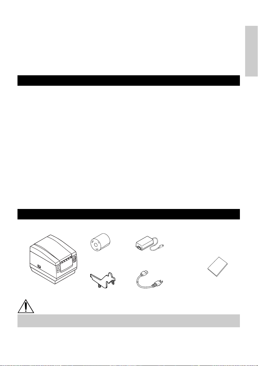
1.2 Unpacking
When unpacking the printer, confirm that the following are provided:
Sample paper roll
Printer
Partition
AC adapter
(provided with the A type only)
User’s manual
AC power cord
(not supplied with Type D)
CAUTION
• Do not use the printer in an environment where condensation can occur. If condensation
forms, leave the power off until it completely evaporates.
— 9 —

2. BASIC SPECIFICATIONS
2.1 Model Classification
The printer models are classified by the following designation method:
ENGLISH
CBM1000 II R F 120 S - L
Label paper function
no display: Nothing
L: Label interval detection
Power supply
S: Standard type
Model Name
*Dedicated adapter type and power cord:
31AD-U (AC 120 V 3-wire cord)
31AD-E (AC 230 V Class I cord)
2.2 Outer Appearance and Component Parts
CBM1000II S CBM1000II A/CBM1000II D
Printer cover
(Power supply built-in)
A: AC adapter type
D: Without AC adapter
Attached power cord specification
120: For AC 120 V
230: For AC 230 V
024: Without AC adapter
Character Set
F: International
Interface
R: Serial (RS-232C)
P: Parallel
(IEEE 1284 compliant)
Printer cover
Power switch
POWER lamp
ERROR lamp
FEED switch
Drawer kick-out connector
Grounding terminal
Inlet
Interface connector
Ejector
Top cover
Power box
— 10 —
Power switch
Interface connector
Ejector
Top cover
POWER lamp
ERROR lamp
FEED switch
Drawer kick-out
connector
Grounding terminal
Power connector
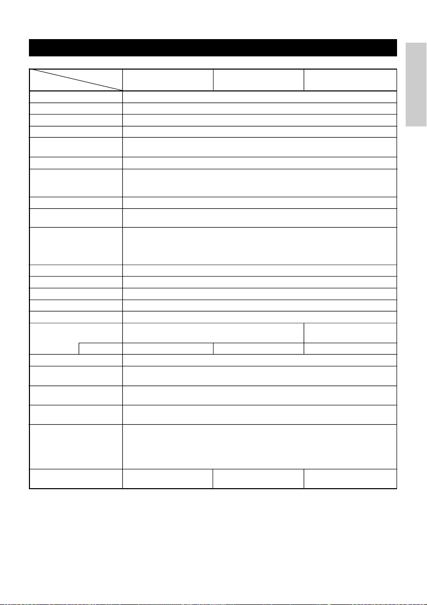
2.3 Basic Specifications
Model CBM1000II RF230S/A
Print method
Print width
Dot density
Print speed
Number of print
columns*
2
Character size
Character type code
page
Logo registration/print
Types of bar code
Line spacing
Paper roll
Label detection
Interfacing
Input buffer
Supply voltage
Power consumption
AC adapter specification
Type
Weight
Outside dimensions
Operating temperature
and humidity
Storage temperature and
humidity
Reliability
Safety Standard*
3
CBM1000II RF120S/A
CBM1000II PF120S/A
Line thermal dot print method
72 mm/576 dots, (54 mm/432 dots)*
8 × 8 dots/mm (203 dpi)
150 mm/sec (Fastest, print density standard level), (1,200 dot lines/sec)
1
Font A: 48/42 (36/30)*
Font B: 64/56 (48/40)*
columns (12 × 24)
1
columns (9 × 24)
Font A: 1.25 × 3.00 mm; Font B: 0.88 × 3.00 mm
Alphanumeric characters, International characters, Code pages PC437,
Katakana, PC850, PC860, PC863, PC865, PC852, PC866, PC857, and Windows
code page
Capable of registering user-defined characters and logos into flash memory.
UPC-A/E, JAN (EAN) 13/8 columns, ITF CODE 39, CODE 128, CODABAR,
CODE 93
4.23 mm (1/6 inches), selectable using commands
Thermal paper roll: 80 mm (58 mm) × ø 83 mm
Thermal Label paper roll : 80 mm (58 mm) × ø 83 mm
(See “ Print Paper Specifications”.)
Selects the L-Spec. (factory option)
Serial (RS-232C), Parallel (IEEE1284 compliant, Bi-directional communication)
4K bytes (72 bytes selectable with a DIP switch)
S type: AC 120/230 V ±10%; A type/D type: DC 24 V ±7%
Approx. 100 W
Rated input: AC 120 to 240 V, 50/60 Hz, 120 VA
Rated output: DC 24 V, 1.9 A (Peak 3.5A)
31 AD-U 31 AD-E
S type: Approx. 2.0 Kg; A type/D type: Approx. 1.4 Kg
S type: 145 (W) × 190 (D) × 157 (H) mm
A type/D type: 145 (W) × 190 (D) × 114 (H) mm
5 to 40°C, 35 to 85% RH (No condensation)
–20 to 60°C, 10 to 90% RH (No condensation)
Print head life: Pulse resistance 1 × 10
Wear resistance 100 Km (At normal temperature/humidity
Auto cutter life: 500,000 times of cutting (At normal temperature/humidity
with recommended paper used)
with recommended paper used)
UL, C-UL, FCC Class A TÜV, GS, CE marking UL, C-UL, FCC Class A,
CBM1000II PF230S/A
1
8
pulses (Print ratio 12.5%)
CBM1000II RF024D
CBM1000II PF024DItem
—
—
TÜV, GS, CE marking
ENGLISH
1
*
Represents the value when a 58 mm wide paper roll is used (User selectable).
2
*
The number of printable columns is selectable with a DIP switch.
3
Represents the safety standards acquired when CBM-made adapters (31AD series) are used.
*
— 11 —
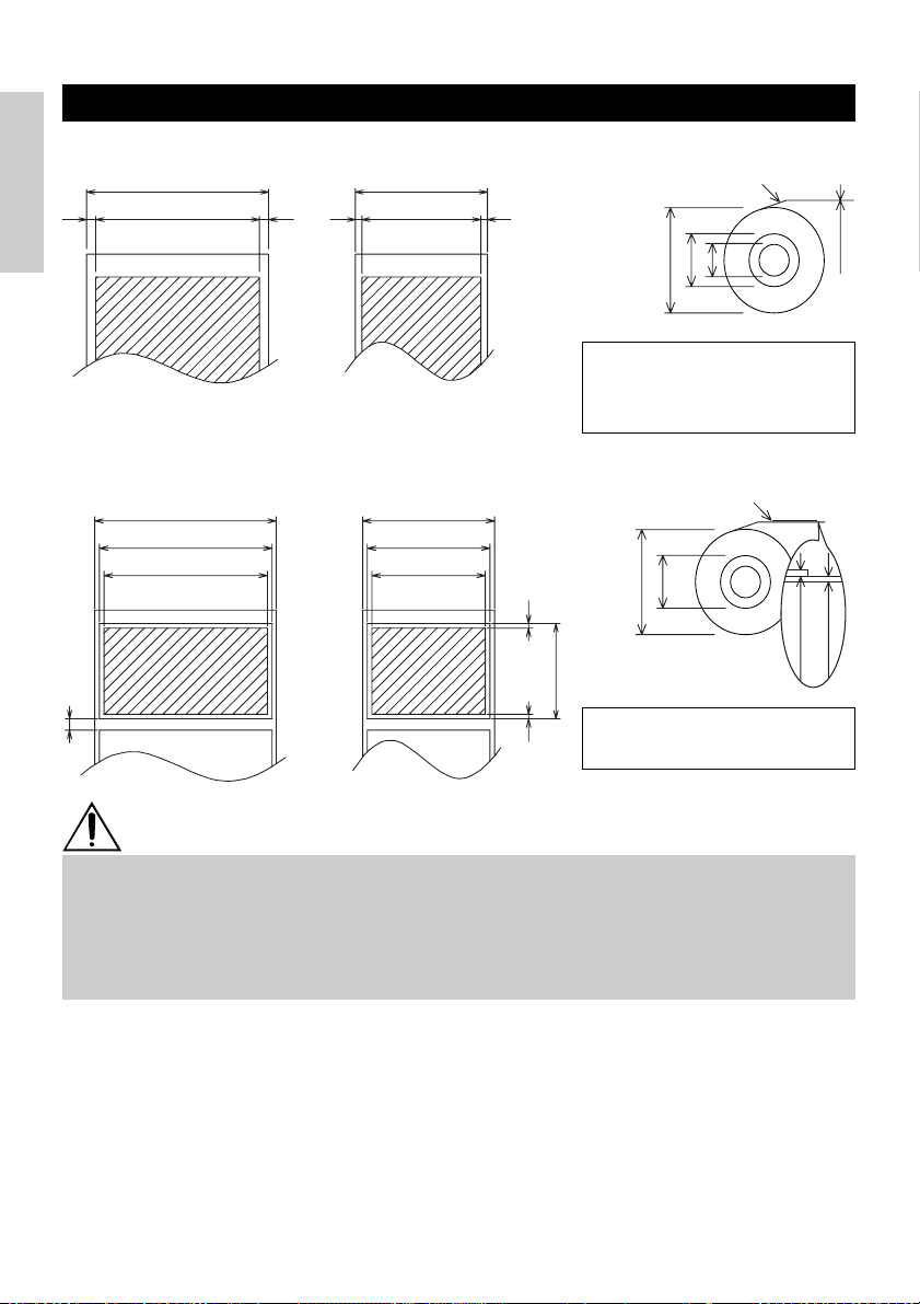
2.4 Print Paper Specifications and Print Position
ø25~28
65~85 µm
(1) Thermal Paper roll
Paper width 80 +0/-1
Maximum print area 72
4422
ENGLISH
Paper width 58
Maximum print area 54
(Recommended papers)
TF50KS-E2C from Nippon Paper
KP50 from Shin-Ohji Paper
Unit: mm
F230AA or HP220A from Mitsubishi
Paper or equivalent
ø83 or less
Printing surface
ø12
ø18
60~80 µm
(2) Thermal label sheet (label gap detection) * Only L-Spec.
Base sheet width: 80 +0/-1
Max. label width: 76
Maximum print area 72
Minimum label gap
4
Base sheet width: 58 +0/-1
Max. label width: 54
Maximum print area 50
Approx. 2Approx. 2
25
Minimum label length
(Recommended papers)
KPT86S/G63BC P22 from Ohji Tac.
ø83 or less
Printing surface
60 µm or less
or equivalent
Unit: mm
CAUTION
• A roll paper not complying with the specifications may cause some departure in print tone.
Adjust print tone with the DIP switch (see “Setting DIP Switches”).
• Do not paste paper end to the core as it may cause coloration or faint letters if printed
documents are exposed to a particular chemical or oil afterwards.
• Rubbing the document surface with your nail or metallic device may cause coloration.
• Coloration occurs at a temperature of around 70°C or above. Keep documents away from
heat, moisture, or light.
— 12 —
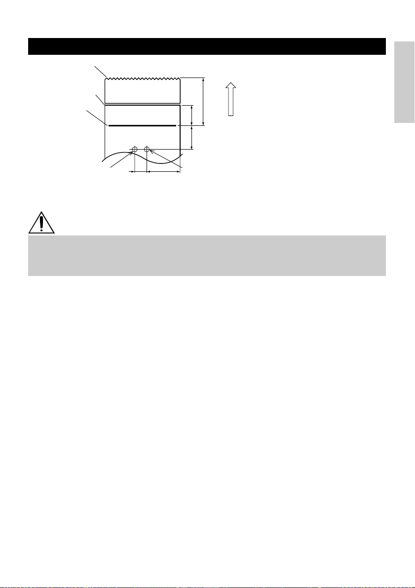
2.5 Sensor Position and Cutter Position
Manual cutting
position
Auto cutting position
Top print line
Approx. 27
Approx. 13
Approx. 17
Paper feed direction
ENGLISH
Paper end sensor
(11mm) (40mm)
Label gap sensor
Unit: mm
CAUTION
• Observe the following rules on the auto cutter usage:
• Every cut paper should be no less than 10 mm in length. Thin paper strips can cause
paper to jam.
• When cutting a label roll, be sure to cut the base sheet. Never cut labels (tags).
— 13 —
3. OPERATION
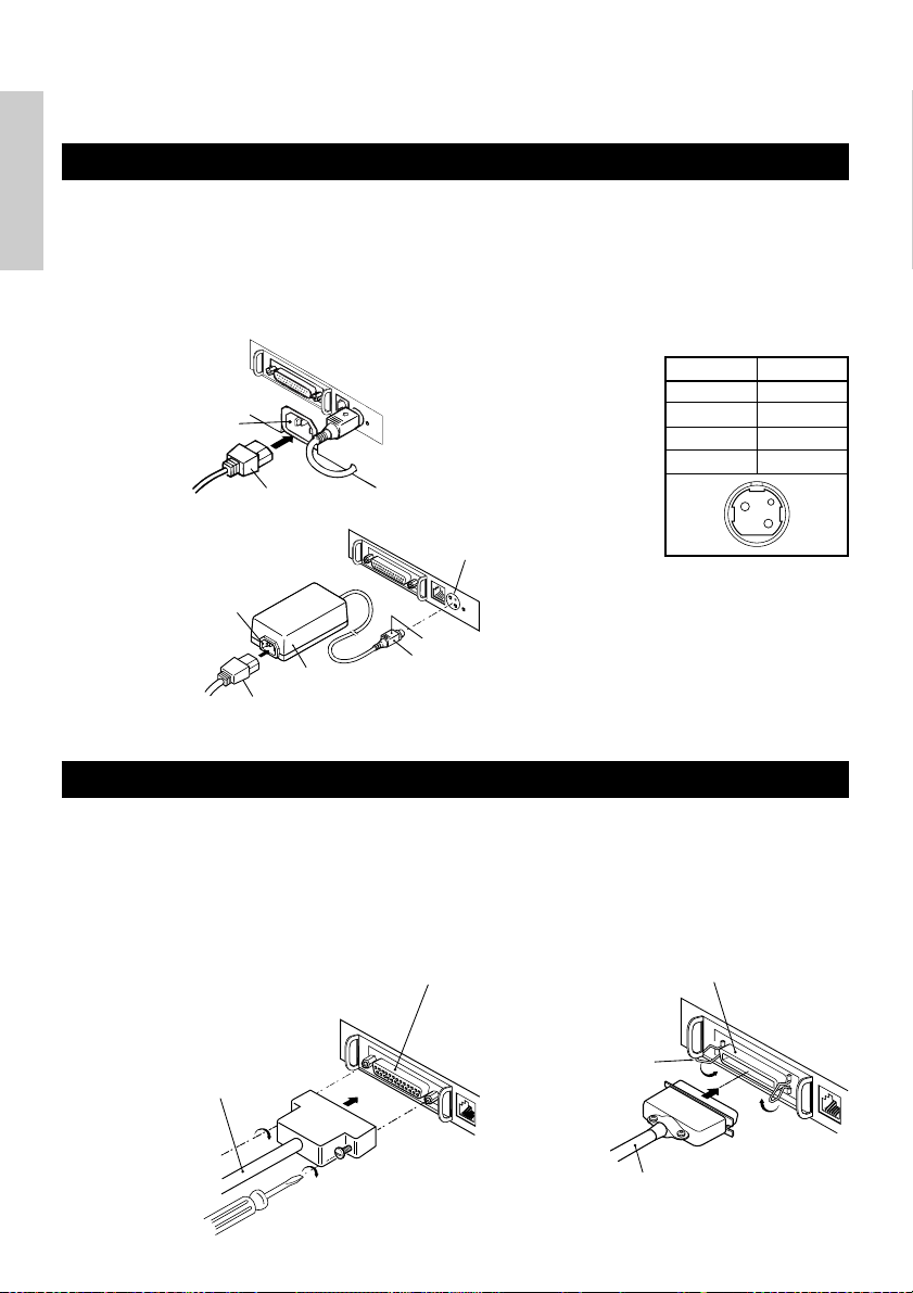
3.1 Connecting the AC Adapter and AC Power Cord
1 Turn off the power of the printer.
ENGLISH
2 For the AC adapter type only: With the flat side of the AC adapter’s cable connector
facing upward, insert the cable connector into the power connector on the back side of
the printer.
3 Connect the AC power cord to the inlet of the printer, and insert the AC power-cord
plug into a suitable wall outlet.
Standard type
AC adapter type
Inlet
AC power cord
Inlet
AC adapter cord
AC adapter
Power connector
Flat side
Cable connector
Power connector pin configuration
No.
1
2
3
SHELL
Connector used:
TCS7960-53-2010 (Hosiden) or
equivalent
Applicable connector:
TCP8927-63-1100 (Hosiden) or
equivalent
TCP8927-53-1100 (Hosiden) or
equivalent
Function
+24
GND
N.C
F. G
1
3
2
3.2 Connecting Interface Cables
1 Turn off the power of the printer. (As well as the connected host computer.)
2 Orient the interface cable terminal correctly and insert it into the interface connector.
3 Secure the cable terminal as shown below.
Serial interface cable: Fasten the connector with screws.
Parallel interface cable: Hold the connector with clamps.
4 Connect the other end of the interface cable to the host computer.
Serial interface connector Parallel interface connector
Clamps
Serial interface cable
Parallel interface cable
— 14 —
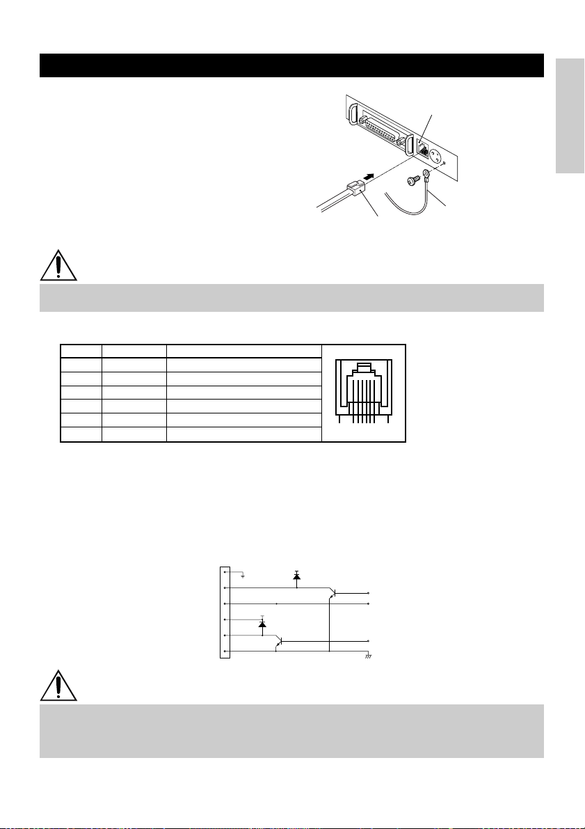
3.3 Connecting the Drawer Kick-Out Connector
1 Turn off the power of the printer.
2 Orient the drawer kick-out cable connector
correctly, insert it into the drawer kick-out
connector on the back of the printer.
3 Fasten the ground wire to the ground
connector on the printer with a screw.
Drawer kick-out connector
ENGLISH
Drawer kick-out cable
connector
Ground wire
CAUTION
• Do not connect any other device than the specified drawer (Solenoid) to the drawer kick-out
connector. (Do not connect a telephone line either.)
(1) Connector Pin Configuration
No. Signal
FG
1
DRAWER 1
2
DRSW
3
VDR
4
DRAWER 2
5
GND
6
Frame Ground
Drawer 1 drive signal
Drawer switch input
Drawer drive power supply
Drawer 2 drive signal
Common ground on circuits
Function
61
(2) Electrical characteristics
1) Driving voltage: 24 VDC
2) Driving current: Approx. 1 A max. (shall not exceed 510 ms.)
3) DRSW signal: Signal levels: “L”=0 to 0.5 V, “H”=3 to 5 V
(3) DRSW signal
DRSW signal status can be tested with the DLE+EOT, GS+a, or GS+r command or at pin 34
on the parallel interface port.
(4) Drive Circuit
1
2
3
4
5
6
VDR
VDR
Connector used:
TM5RJ3-66 (Hirose) or
equivalent
Applicable connector:
TM3P-66P (Hirose) or
equivalent
CAUTION
• No output is produced while printing.
• The drawers 1 and 2 cannot be driven simultaneously.
• A solenoid used for the drawer should be of 24 Ω or more. The output current should be
kept at 1 A or less; otherwise, breakdown or burning could occur.
— 15 —
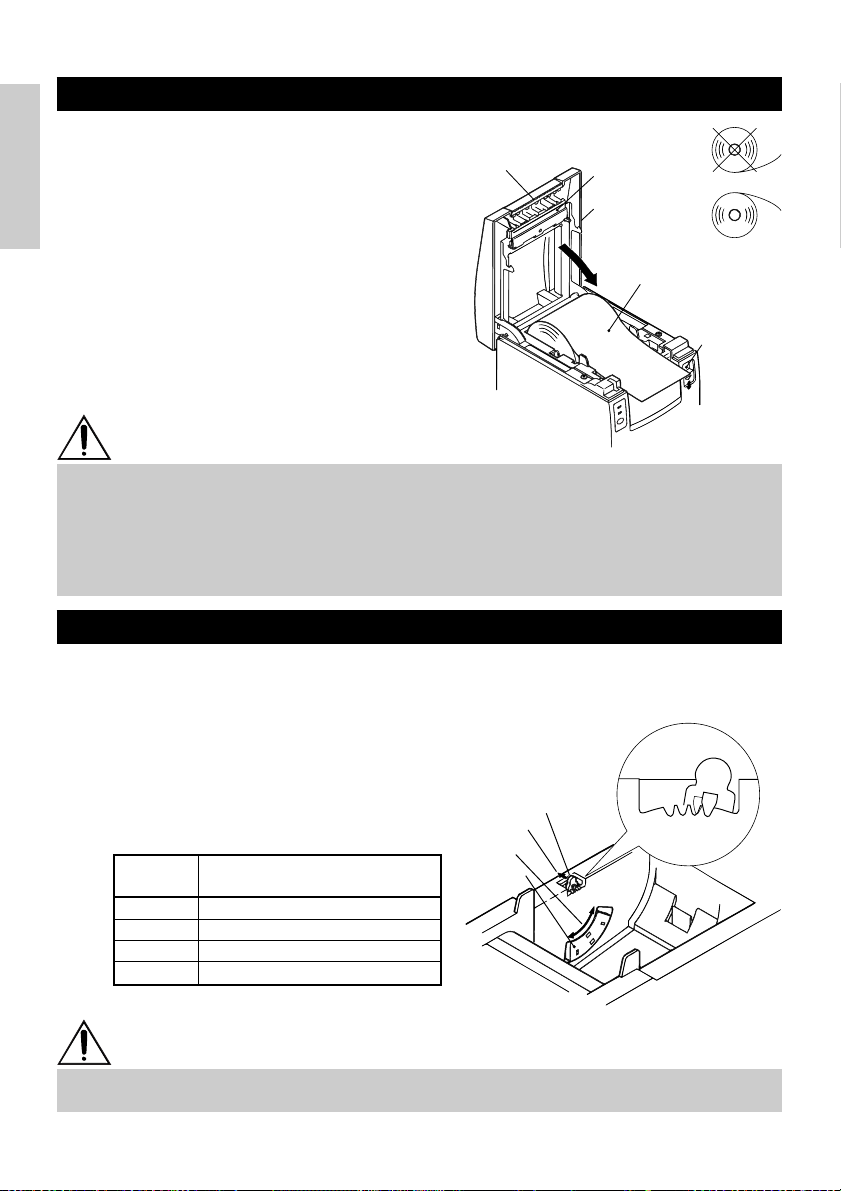
3.4 Setting/Replacing Paper Rolls
1 Turn on the printer.
2 Push the ejector in the direction shown to
unlock the printer cover.
3 Placing your hands on both sides of the
ENGLISH
printer cover, open it until it comes to a
Tear bar
Print head
Printer cover
stop.
4 Check the winding direction of the paper
roll, and then place it into the paper roll
holder correctly.
Paper roll
5 With the end of the paper approx. 5 cm out
of the case of the printer, close the printer
cover. Push lightly on the printer cover
until a “click” is heard.
6 Remove an excess length of paper with
the tear bar. (Manual cutter)
CAUTION
• Always use the specified types of paper roll.
• Use of other types of paper roll may not be able to guarantee the specified print quality or
service life of the printer.
• When opening the printer cover, do not apply an excess force to it beyond its stop position.
• The print head becomes hot immediately after printing. Do not touch it with your hand.
During printing, do not open the printer cover. Do not hold the end of the paper as it prints
and ejects. Doing so may cause the paper to jam.
3.5 Adjusting the Paper Near-End Sensor
1 Open the printer cover.
2 Push the sensor knob in the direction of
arrow 1 to disengage its claw (Or unlock
the sensor unit), and then adjust the
sensor unit to a desired paper remaining
position within the range shown by arrow
2.
3 The following table shows the relationship
between adjustment positions and levels
of paper roll remaining. (A rough guide)
Adjustment
position
1
2
3
4
Level of paper remaining
(Paper roll outside diameter/mm)
ø
18
ø
21
ø
24
ø
27
* When specified paper rolls are used.
Sensor knob
Arrow 1
Arrow 2
Sensor unit
4321
Adjustment
position
Ejector
CAUTION
• Use the level of paper remaining (Paper-roll outside diameter) just as a guide as it varies
depending on the particular printer and paper rolls used.
— 16 —
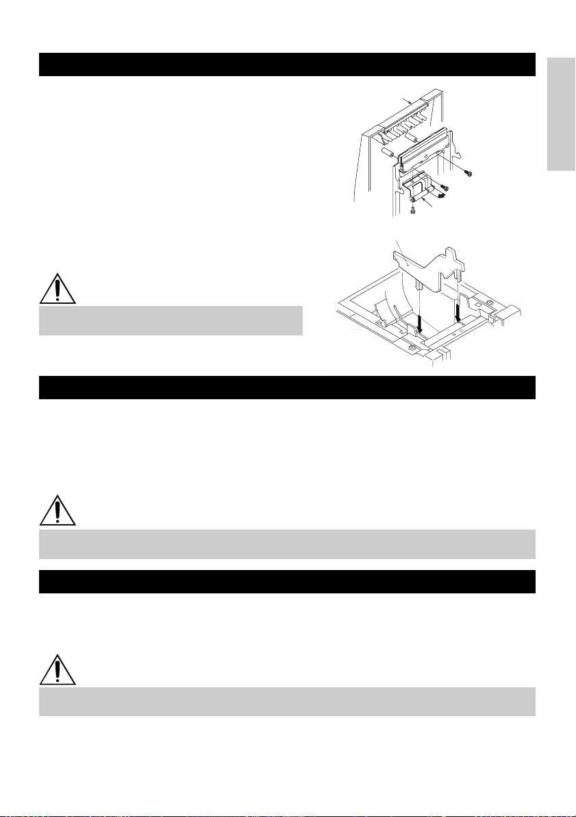
3.6 Using 58 mm Wide Paper Rolls
1 Turn off the power of the printer.
2 Open the printer cover.
3 Take off two screws and remove printer
cover.
4 Take off damper retention screws,
reposition damper (11 mm) in the direction
of the arrow, then secure it with the
original screws again.
5 Replace printer cover on printer.
6 Install the supplied partition into the
position as illustrated.
7 Change DIP switch setting for 58 mm roll
paper, by referring to “SETTING DIP
SWITCHES”.
Printer cover
Damper
Partition
CAUTION
• Do not change DIP switch setting from 58 mm
into 80 mm roll paper in the middle of printing.
3.7 Removing Jammed Paper
1 Turn off the power of the printer.
2 Open the printer cover.
3 Remove the paper jam including any paper chips remaining. (Also take out the paper
roll from the holder.)
4 Close the printer cover.
5 Turn on the printer. The auto cutter mechanism is initialized and the alarm is cleared.
ENGLISH
CAUTION
• The print head becomes hot immediately after printing. Do not touch it with your hand. Do
not touch the heating element of the head with a bare hand or metal object either.
3.8 Cleaning the Print Head
1 Open the printer cover.
2 Wipe off stains, such as dust and the like, on the heating element of the head using a
cotton swab soaked in ethyl alcohol.
CAUTION
• The print head becomes hot immediately after printing. Do not touch it with your hand. Do
not touch the heating element of the head with a bare hand or metal object either.
— 17 —
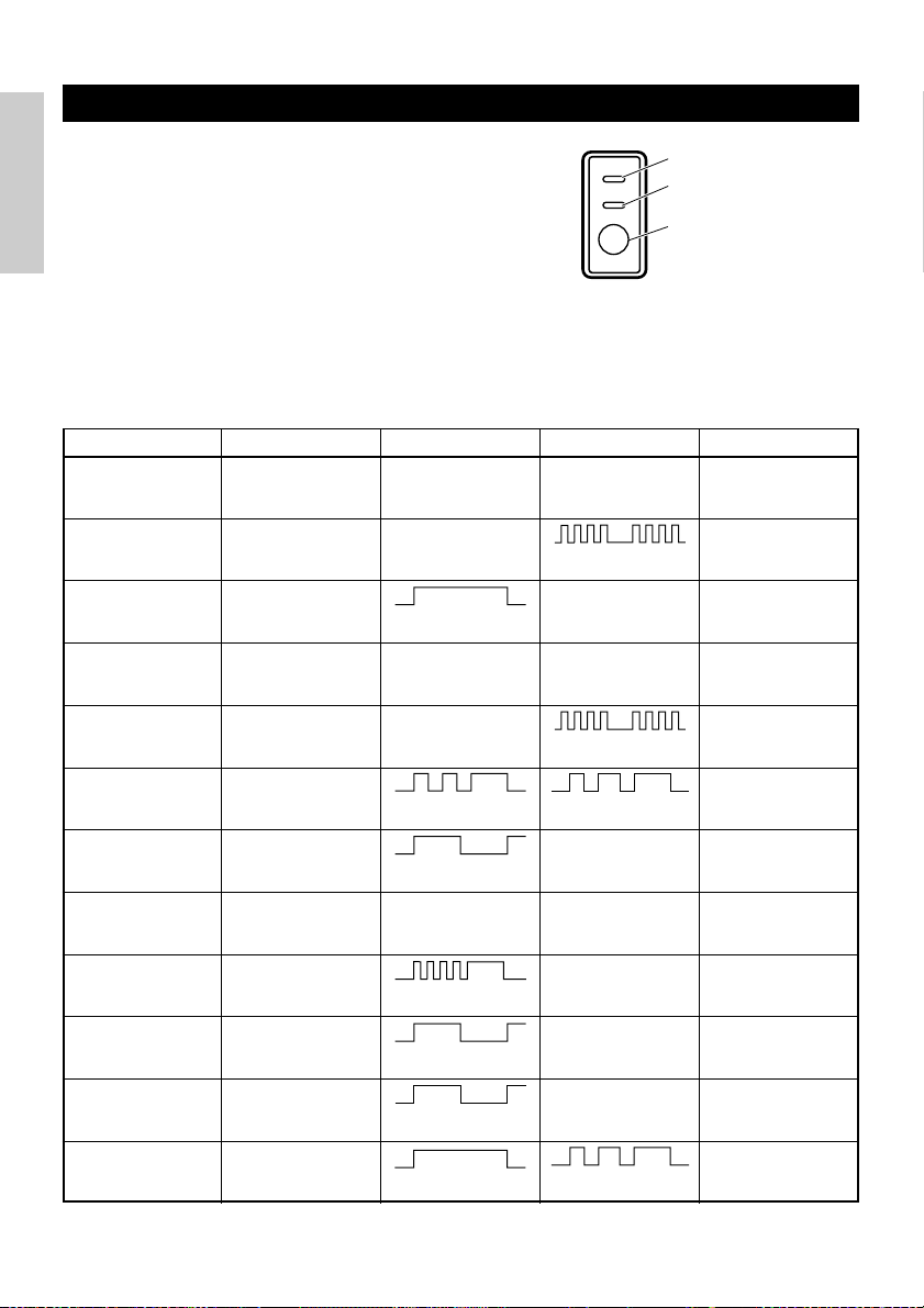
3.9 Operation Panel and Error Indication
1 POWER lamp (Green)
Lights when the power is turned on. It blinks when
a memory check error has occurred.
2 ERROR lamp (Red)
ENGLISH
Lights or blinks to show different error states. It
also blinks while the printer is waiting for a macro
POWER
ERROR
FEED
POWER lamp (Green)
ERROR lamp (Red)
FEED switch
to be executed.
3 FEED switch
Pressing this switch briefly causes one line of
paper feeding.
While a macro is waiting to be executed, pressing
the switch causes the macro to be executed.
4 Buzzer
A buzzer sound alerts the operator to an error.
Error indication POWER lamp ERROR lamp Buzzer Recovery method
Memory Check
error
Cover open Lights Lights
Head overheat Lights
Paper near-end
Paper end Lights Lights
Cutter motor lock Lights
Quick blinking Lights — Not recoverable
(Four short beeps) × 2
Slow blinking
Lights Lights —
(Four short beeps) × 2
Quick and slow blinking
Three long beeps
—
Close the cover.
Recovers automatically
when the temperature
returns to normal.
Set a new paper
roll.
Set a new paper
roll.
Remove paper
jams.
Macro execution
wait
Low voltage error Lights — Not recoverable
High voltage error Lights — Not recoverable
Waiting for label
cutter action
Waiting for label
discharge
Label detection
error
Lights
Off —
Off —
Off
Slow blinking
Lights
Quick and slow blinking
Slow blinking
Slow blinking
Three long beeps
—
Press the FEED
switch.
Press the FEED
switch.
Remove label from
peeler.
Set the specified
label roll.
— 18 —

Description of errors
Memory Check error:
This error occurs if a memory read-after-write check or FROM sum check has resulted in an error
(unrecoverable error).
Cover open:
When you open the printer cover, the cover open sensor is activated, causing the ERROR lamp to
light and the printing operation to stop. (Not recoverable error)
Head overheat:
To protect the print head from overheating, the head temperature sensor is activated if the head
temperature rises over approx. 65°C, causing the ERROR lamp to blink and the printing operation to
stop. Printing resumes automatically when the head temperature lowers below approx. 60°C. (Auto
recoverable error)
Paper near-end:
As the paper roll diameter becomes small, the Paper near-end sensor is activated and causes the
ERROR lamp to light, indicating the paper supply has become low. (See “Selecting the paper sensor
valid for paper end signal output” and “Selecting the Paper Near-End Sensor valid for print stop”.)
Paper end:
When the paper roll has run out, the Paper end-sensor located near the print head on the paper
path detects the end of the paper roll, causing the ERROR lamp to light and printing to stop. (See
“Selecting the paper sensor valid for paper end signal output” and “Selecting the Paper Near-End
Sensor valid for print stop”.)
Cutter motor lock:
While the cutter motor is running, if the cutter position detecting sensor inside the cutter unit
remains ON or OFF for approx. 1 second or more, the printer determines that the motor has locked,
causing the cutter operation and printing to stop. (See “Removing Jammed Paper”.)
Low voltage error:
Occurs when the voltage supplied to the printer decreases ; if this has occurred, turn the power off
immediately. (Not recoverable error)
High voltage error:
Occurs when the voltage supplied to the printer increases ; if this has occurred, turn the power off
immediately. (Not recoverable error)
Waiting for label cutter action:
Wait until the label discharged by the GS+FF (Cut Label and Discharge) command is cut by the
manual cutter and the FEED switch is pressed. If “No Cutter” or “No Peeling Mechanism” is
selected, the printer becomes Busy.
Waiting for Label Discharge:
Waiting for a label to be removed from the base sheet after it was discharged by the GS+FF (Cut
Label & Eject) command (if the peeler is selected). The printer becomes Busy.
Label detection error:
Label gaps or black marks could not be detected, or the label sheets used do not fall in the specified
length limits.
If a label detection error occurs even though the label sheets used fall in the specified length limits,
it is most likely that the sensor or its peripheral electronics is defective. The printer becomes Busy.
ENGLISH
— 19 —
3.10 Self-printing
=== Hexadecimal Dump ===
To terminate hexadecimal dump,
Press FEED switch three times.
1
B
40 73 6D 70 6C 65 0A 30 31 32 .@samp l e. 01
33 34 35 36 37 38 39 41 42 43 44 3456789ABCD
45 46 47 48 49 4
A 4B 4C 4D 4F
50 EFGHI JKLMOP
51 52 53 54 55 56 57 58 59 5
A 0D
QRSTUVWXYZ .
61 62 63 64 65 66 67 68 69 6
A 6B
abcd e f gh i j k
6
C 6D 6E 6F
70 71 72 73 74 75 76 lmnopq r s t u v
77 78 79 7
A 0D 0A 0A 0A
wxyz....
=== Completed ===
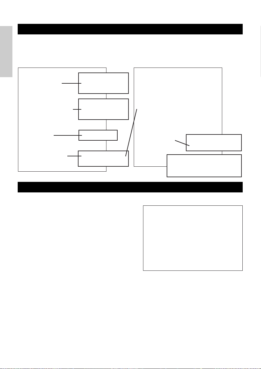
When the power is turned on while the FEED switch is pressed, the printer will
perform preset printing. After the self-printing is completed, the printer will return to
the normal operation conditions.
ENGLISH
CBM1000
MPV3.xx
LPV3.xx
Serial Interface
Baud Rate : 19200 bps
Data Bit : 8 bits
Parity : None
Handshake : DTR/DSR
Buffer Size
4K bytes
Dip Switches
DS1
1 2 3 4 5 6 7 8
ON o o
OFF o o o o o o
Program & loader
versions
Interface and its
status (serial I/F in
this example)
Buffer size
DIP switch status
(DS3 for serial only)
3.11 Hexadecimal Dump
1 Hexadecimal dump function allows data
sent from the host computer to be printed
in hexadecimal numbers as well as in
characters corresponding to the numbers.
2 Starting hexadecimal dump
To start hex dump, turn the printer On
while pressing and holding the FEED
switch, with the printer cover left open.
When you close the printer cover, the
printer first prints “Hexadecimal Dump”,
then prints all the subsequent data in hex
and characters.
DS2
1 2 3 4 5 6 7 8 9 10
ON o
OFF o o o o o o o o o
DS3
1 2 3 4 5 6 7 8
ON o
OFF o o o o o o o
! ”#$ %&’ ( ) *+,–. /0123456789: ;<=> ?@A B C
DEFGHIJKLMNOPQRSTUV
Hi j klm n op qrstuvw xyz{ | }~........
•
•
•
<Example of hexadecimal dump>
W
X YZ[ \ ] ^_ `abcdefg
If the Auto Cutter is used, the
paper is cut into pages each time
a page is printed.
All the printable
characters are printed.
NOTE
• If a character is not available corresponding to the data received, “ . ” is printed instead.
• During hexadecimal dump, no other functions than DLE EOT and DLE ENQ work.
• If the data received is not enough for a full line, pressing the FEED switch causes the line to
be printed.
3 Quitting hexadecimal dump
The printer exits Hex Dump mode when it is turned off, the FEED switch is pressed 3
times consecutively, or the printer receives a Reset signal from the interface, after hex
dump is completed.
— 20 —
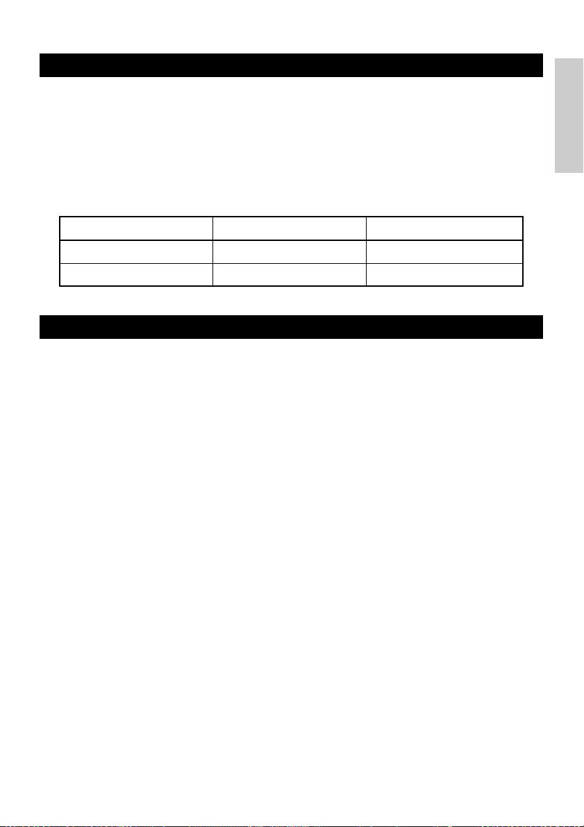
3.12 Printer Buffer
3.12.1 Buffering
The printer buffer has a capacity of 4K bytes (DS1-6: OFF). The host is released
immediately after it transfers data to the printer.
3.12.2 Buffer Full Busy
If the printer buffer becomes full, the Busy/DTR signal is set to “High” to indicate
“Buffer Full” to the host. The printer is unable to receive data from the host while in
Buffer Full.
ENGLISH
Printer Buffer
4K bytes
72 bytes
Note: The printer buffer can be initialized with DS1-6.
Busy/DTR Asserted
128 bytes remaining
20 bytes remaining
Busy/DTR Reset
256 bytes remaining
30 bytes remaining
3.13 Device ID
On receiving a Device ID request from the host, the printer returns a device ID as
shown below through the parallel interface:
<00>H<31>H
MFG:CBM;
CMD:CBM;ESC/POS;
MDL:CBM1000;
CLS:PRINTER;
The first 2 bytes of the device ID indicates the total length of the ID including itself.
— 21 —

4. SETTING DIP SWITCHES
4.1 Location of DIP Switches
1 Turn off the power of the printer.
ENGLISH
2 Open the printer cover.
3 Remove the paper roll and the DIP switch
cover.
4 After completing the setting, place the
cover to the original position.
DIP switch cover
CAUTION
• Do not make settings while the printer is
* DIP switch 3 is only for the
serial interface.
turned on.
4.2 Table for Setting DIP Switches
4.2.1 DIP switch 1
No. Function ON OFF Factory presetting
1-1
1-2
1-3
1-4
1-5
1-6
1-7
1-8
* It will be different according to the setting of paper width (DS1 – 3).
Print density
No.
Note: If print density is set to level 2 (Standard) or over, print speed may decrease.
Auto cutter
Unused
Paper width
Print columns*
CR mode
Input buffer
Print density
1-7
1-8
Available
-
58 mm
42 columns (80 mm)
30 columns (58 mm)
LF operation
72 bytes
Print density (See the tabel below.)
Level 1
(Light)
OFF
OFF
Level 2
(Standard)
ON
OFF
Not available
-
80 mm
48 columns (80 mm)
36 columns (58 mm)
Ignored
4K bytes
Level 3
(Slightly dark)
OFF
ON
ON
OFF
OFF
OFF
OFF
OFF
ON
OFF
Level 4
(Dark)
ON
ON
— 22 —

4.2.2 DIP switch 2
No. Function ON OFF Factory presetting
2-1
2-2
2-3
2-4
2-5
Unused
Character code (See the table below.)
–
–
OFF*
OFF*
OFF*
OFF*
OFF
ENGLISH
Condition for BUSY to
2-6
2-7
2-8
2-9 OFFLabel length set Command Auto
2-10 OFFLabel Peeler Available Not available
* Depends on destinations.
occur
Paper
Detection Black mark Label interval
Reception buffer full
Thermal label paper
Off-line and reception
buffer full
Thermal paper
OFF
OFF
OFF
4.2.3 DIP switch 3
No. ON OFF Factory presetting
3-1
3-2
3-3
3-4
3-5
3-6
3-7
3-8
* DIP switch 3 is only for the serial interface.
Selection of character code tables
Code
Code 437 (USA: Standard Europe)
Katakana (Japanese)
Code 850 (Multilingual)
Code 860 (Portuguese)
Code 863 (Canadian-French)
Code 865 (Nordic)
Code 852 (Eastern Europe)
Code 866 (Russian)
Code 857 (Turkish)
Windows Code 1252
Not defined
Blank page
Function
Bit length
Parity
Odd/even
Communication mode
Baud rate (See the table below.)
DSR Reset DSR
INIT
No.
7 bits
Available
Even number
XON/XOFF
Reset
2-2 2-42-3
2-1
OFF
OFF
ON
OFF
OFF
ON
ON
ON
OFF
OFF
ON
OFF
OFF
ON
ON
ON
OFF
OFF
ON
OFF
–
ON
–
ON
OFF
OFF
OFF
OFF
ON
ON
ON
ON
OFF
OFF
–
ON
8 bits
Not available
Odd number
DTR/DSR
—
Baud rate
OFF
OFF
OFF
OFF
OFF
OFF
OFF
OFF
ON
ON
–
ON
Baud rate
• “Blank page” is an area for user
registration, and is blank (space)
by default.
• When “Katakana” is selected, the
international character is set for
Japanese. When the others are
selected, it is set for USA.
No.
4,800 bps
9,600 bps
19,200 bps
38,400 bps
OFF
OFF
OFF
OFF
OFF
ON
OFF
OFF
3-5
OFF
ON
OFF
ON
3-6
OFF
OFF
ON
ON
— 23 —
5. MAINTENANCE AND SERVICE
For the information on maintenance and service, please contact your CBM dealer or
at the following addresses:
ENGLISH
Northern America
CBM America Corporation
Service Center
363 Van Ness Way
Suite 404
Torrance, CA 90501, U.S.A
TEL: +1-310-781-1460
FAX: +1-310-781-9157
E-mail: sales@cbma.com
http://www.cbma.com
Other Areas
Japan CBM Corporation
Information Systems Division
CBM Bldg. 5-68-10, Nakano
Nakano-ku, Tokyo 164-0001, Japan
TEL: +81-3-5345-7540
FAX: +81-3-5345-7541
E-mail: info-sys@jcbm.co.jp
http://www.jcbm.co.jp
CAUTION
• If the printer has a fatal error, emission of smoke, fire, or other problem, immediately abort
the current print session and unplug the printer from the supply outlet. Then call the
contacts listed above or your local CBM dealer.
• Never attempt to disassemble or repair the printer by yourself.
— 24 —

FRANÇAIS
FRANÇAIS
— 1 —

TABLE DES MATIÈRES
1. PRÉSENTATION GÉNÉRALE ............................................................... 9
1.1 Caractéristiques ........................................................................................ 9
1.2 Déballage ................................................................................................... 9
2. SPÉCIFICATIONS DE BASE ............................................................... 10
2.1 Classification des modèles .................................................................... 10
2.2 Apparence extérieure et nomenclature ................................................10
2.3 Spécifications de base............................................................................ 11
2.4 Spécifications du papier et position d’impression .............................. 12
2.5 Position du capteur et position du massicot........................................ 13
FRANÇAIS
3. FONCTIONNEMENT........................................................................... 14
3.1 Branchement de l’adaptateur secteur et du cordon d’alimentation .. 14
3.2 Branchement des câbles d’interface ..................................................... 14
3.3 Branchement du connecteur de renvoi du tiroir ................................. 15
3.4 Mise en place/Remplacement des rouleaux de papier .......................16
3.5 Réglage du capteur de fin de papier proche ........................................ 16
3.6 Utilisation de rouleaux de papier de 58 mm de largeur .....................17
3.7 Retrait du papier coincé .........................................................................17
3.8 Nettoyage de la tête d’impression ........................................................17
3.9 Panneau de commande et indication des erreurs ............................... 18
3.10 Impression automatique ......................................................................20
3.11 Vidage hexadécimal ............................................................................. 20
3.12 Tampon de l’imprimante ......................................................................21
3.13 Identification de périphérique ............................................................. 21
4. RÉGLAGES DES COMMUTATEURS À POSITIONS MULTIPLES .... 22
4.1 Emplacement des commutateurs à positions multiples..................... 22
4.2 Tableau pour le réglage des commutateurs à positions multiples .... 22
5. ENTRETIEN ET SERVICE APRÈS-VENTE ......................................... 24
APPENDIX 1. OUTLINE DRAWING .......................................................... i
APPENDIX 2. BLOCK DIAGRAM .............................................................. i
APPENDIX 3. IDENTIFICATION OF SEND STATUS ............................... ii
APPENDIX 4. PARALLEL INTERFACE .................................................... iii
APPENDIX 5. SERIAL INTERFACE .......................................................... v
APPENDIX 6. CONTROL COMMAND ................................................... vii
— 2 —

PRÉCAUTIONS GÉNÉRALES
1 Les informations contenues dans ce mode d’emploi sont susceptibles d’être
modifiées sans préavis.
2 Tous droits réservés. La reproduction en totalité ou en partie de ce
document sans autorisation écrite de CBM Corporation est interdite.
3 Sauf en cas d’explication dans ce mode d’emploi, ne tentez pas d’entretenir,
de démonter ou de réparer vous-même cet appareil.
4 Notez que CBM ne sera pas tenue responsable pour les dommages
attribuables à un fonctionnement ou une manipulation incorrecte, ou à des
environnements de fonctionnement inappropriés qui ne sont pas spécifiés
dans ce mode d’emploi.
5 Faites fonctionner cette imprimante uniquement de la manière décrite dans
ce mode d’emploi afin d’éviter les accidents ou les problèmes.
6 Les données sont en principe réservées à une utilisation provisoire, et ne
sont pas conservées pendant longtemps ou en permanence. Veuillez noter
que CBM ne sera pas tenue responsable en cas de dommage ou de perte de
profits résultant de la perte des données provoquée par des accidents, des
réparations, des tests, ou toute autre occurrence.
7 Si vous avez des questions ou des commentaires concernant les
informations contenues dans ce mode d’emploi, veuillez contacter votre
revendeur CBM.
8 Veuillez noter que CBM ne sera pas tenue responsable pour tout événement
se produisant en faisant fonctionner l’imprimante, malgré les indications du
paragraphe «7» ci-dessus.
FRANÇAIS
— 3 —

PRÉCAUTIONS DE SÉCURITÉ
Veuillez lire attentivement ces PRÉCAUTIONS DE SÉCURITÉ avant d’utiliser
l’appareil pour la première fois. Un fonctionnement incorrect risque de
provoquer des accidents imprévus (incendie, chocs, ou blessures).
● Après avoir lu ce mode d’emploi, conservez-le dans un endroit sûr et facilement
accessible pour référence ultérieure.
● Certaines des descriptions contenues dans ce mode d’emploi peuvent ne pas
s’appliquer à certains modèles d’imprimantes.
Des symboles d’avertissement sont utilisés dans ce mode d’emploi pour
indiquer les précautions à observer rigoureusement afin d’éviter de mettre en
danger les opérateurs ou des tiers ou d’endommager les biens matériels.
FRANÇAIS
● Ce qui suit indique le degré de danger et de dommage encouru si l’imprimante
n’est pas utilisée correctement, sans tenir compte des instructions indiquées par
les symboles d’avertissement.
AVERTISSEMENT
Le non-respect des précautions indiquées par ce symbole peut provoquer des
blessures mortelles ou graves.
ATTENTION
Le non-respect des précautions indiquées par ce symbole peut provoquer des
blessures ou des dommages matériels.
Ce symbole sert à attirer votre attention sur des points importants.
Ce symbole sert à indiquer des actions interdites.
Ce symbole sert à vous avertir d’un risque d’électrocution ou de
dommage électrostatique.
Ce symbole indique la nécessité de débrancher l’imprimante de la
prise murale.
— 4 —

Etiquettes de précaution
• Ne tentez pas d’introduire une fiche (par ex. une fiche
modulaire) autre que la fiche du connecteur de renvoi du
tiroir dans le connecteur de renvoi du tiroir, ceci risquant
d’endommager la connexion téléphonique ou l’imprimante.
AVERTISSEMENT
ATTENTION
• La tête thermique conserve une température
dangereusement élevée immédiatement après usage. Ne la
touchez pas avant qu’elle n’ait refroidi.
AVERTISSEMENT
N’utilisez pas et ne rangez pas cet appareil dans un endroit où il sera exposé à :
• des flammes ou de l’air humide
• la lumière directe du soleil
• de l’air chaud ou aux radiations d’un appareil de chauffage
• une atmosphère mal ventilée
• des réactions chimiques en laboratoire
• de l’huile, des particules d’acier ou de la poussière contenue dans l’air
• de l’air salin ou des gaz corrosifs
• de l’électricité statique ou des champs magnétiques puissants
●Le non-respect de ces avertissements risque de provoquer des
pannes de l’imprimante, une surchauffe, des émissions de fumée,
un incendie ou une électrocution.
Ne laissez pas pénétrer des objets étrangers et ne renversez pas de
liquide dans l’imprimante. Ne placez pas non plus d’objet sur
l’imprimante.
• Ne laissez pas des objets métalliques comme des trombones, des
épingles ou des vis pénétrer dans l’imprimante.
• Ne placez pas un vase ou un pot de fleurs, ou un verre contenant de
l’eau sur l’imprimante.
• Ne renversez pas de café, de boissons fraîches ou tout autre liquide
dans l’imprimante.
• Ne vaporisez pas d’insecticide ou tout autre produit chimique liquide
sur l’imprimante.
●Un objet métallique tombé accidentellement dans l’imprimante
risque de provoquer une panne, un incendie ou une électrocution.
Dans ce cas, mettez immédiatement l’imprimante hors tension,
débranchez-la de la prise d’alimentation et faites appel à votre revendeur
local CBM.
FRANÇAIS
— 5 —

Observez les précautions suivantes pour l’alimentation électrique et le cordon d’alimentation :
•
Ne branchez pas et ne débranchez pas le cordon d’alimentation avec les mains
mouillées.
•
Utilisez l’imprimante uniquement avec la tension d’alimentation et la fréquence
spécifiées.
•
Utilisez uniquement l’adaptateur secteur spécifié avec l’imprimante.
•
Vérifiez si la prise sur laquelle l’imprimante est alimentée a une capacité suffisante.
•
Ne branchez pas le cordon d’alimentation dans une prise comportant de la poussière
ou des débris.
•
N’alimentez pas l’imprimante à partir d’un circuit d’alimentation ou d’une prise de
courant servant déjà à d’autres appareils.
•
N’utilisez pas un cordon déformé ou endommagé.
●
Le non-respect des procédures correctes risque de provoquer une panne de
l’imprimante, une émission de fumée, un incendie ou une électrocution.
●
FRANÇAIS
Une surcharge risque de provoquer une surchauffe du câble d’alimentation ou de
déclencher le disjoncteur.
•
Ne laissez pas d’objet sur le cordon d’alimentation. Ne placez pas l’imprimante dans un
endroit où le cordon risque d’être piétiné.
•
Ne tentez pas de modifier inutilement le cordon d’alimentation.
•
N’utilisez pas et ne transportez pas l’imprimante avec le cordon d’alimentation plié,
tordu ou tiré.
•
Ne placez pas le cordon d’alimentation à proximité d’un appareil de chauffage.
●
Le non-respect de ces précautions risque de provoquer la rupture des fils ou de l’isolation et
de causer des fuites, une électrocution ou une panne de l’imprimante. Contactez votre
revendeur CBM si le cordon d’alimentation est endommagé.
•
Alimentez l’imprimante à partir d’une prise murale pratique et facilement
accessible en cas d’urgence.
•
Ne laissez pas d’objets autour de l’imprimante afin qu’elle soit toujours
facile d’accès.
●
L’imprimante peut ne pas être mise à l’arrêt immédiatement en cas
d’urgence.
•
Introduisez à fond la fiche d’alimentation dans la prise.
•
Si l’imprimante n’est pas utilisée pendant une période prolongée,
débranchez-la de la prise d’alimentation.
Ne manipulez pas l’imprimante de la manière suivante :
•
Ne soumettez pas l’imprimante à des secousses ou des chocs violents (par ex.
piétinement, chute ou coups avec un objet dur).
•
Ne tentez pas de démonter ou de modifier l’imprimante.
•
Ne nettoyez pas l’imprimante avec un solvant organique, comme de
l’alcool, un diluant de peinture, «trichlen», benzène ou cétone.
●
Le non-respect des procédures correctes risque de provoquer une
Benzine
Thinner
panne de l’imprimante, une surchauffe, une émission de fumée, un
incendie ou une électrocution.
Installez, utilisez et rangez l’imprimante hors de la portée des enfants.
●
Le sac en plastique dans lequel l’imprimante est emballée doit être mis au rebut
correctement et conservé hors de la portée des enfants. Une suffocation peut se produire si
le sac est mis sur la tête.
●
Les appareils électriques risquent de provoquer des blessures ou des accidents inattendus
s’ils sont manipulés ou utilisés de manière incorrecte.
●
Laissez le cordon d’alimentation et les câbles de signaux hors de la portée des enfants. Les
enfants doivent également être interdits d’accès aux pièces internes de l’imprimante.
— 6 —

ATTENTION
Placez l’imprimante sur une surface plate.
●
Elle risque sinon de tomber de sa position.
Choisissez avec soin l’emplacement de l’imprimante et faites attention à ce que vous
placez à proximité.
•
Veillez à ce qu’un mur ou un morceau de tissu ne bloque pas les orifices de ventilation
de l’imprimante.
•
N’utilisez pas l’imprimante avec un objet placé dessus.
●
Veillez à éviter la formation de température interne qui peut provoquer un incendie
et déformer le boîtier.
•
Evitez d’utiliser l’imprimante à proximité d’une radio ou d’un téléviseur ou de
l’alimenter à partir de la même prise que ces appareils.
•
Pour les interconnexions, utilisez des câbles armés ou torsadés et des noyaux en ferrite,
ou d’autres dispositifs anti-bruit.
•
Evitez d’utiliser l’imprimante avec un appareil produisant une source de bruit puissante.
●
L’imprimante peut avoir un effet négatif sur les transmissions radio ou télévisées.
Dans certains cas également, les appareils électriques proches peuvent influencer
l’imprimante et causer des erreurs de données ou des pannes.
Utilisez l’imprimante avec sa fiche de terre raccordée à une installation de mise à la terre
pratique.
●
Des électrocutions risquent de se produire en cas de fuites.
Ne branchez pas la fiche de terre de l’imprimante sur l’une des installations suivantes :
•
Canalisation de gaz
●
Une explosion de gaz peut se produire.
•
Terre d’une ligne téléphonique
•
Paratonnerre
●
En cas de foudre, une surtension de courant importante peut provoquer un
incendie ou des chocs.
•
Canalisation d’eau
●
Les tuyaux d’eau en plastique ne doivent pas être utilisés pour la mise à la terre.
(Ceux approuvés par le Département des Eaux peuvent être utilisés.)
Avant de brancher ou de débrancher le fil de terre de l’imprimante, débranchez tout
d’abord de la prise d’alimentation.
Avant de brancher ou de débrancher le cordon d’alimentation ou de raccorder des
câbles de ou vers l’imprimante, mettez la totalité du système hors tension.
Pour débrancher un câble, ne le tirez pas. Maintenez-le toujours par la fiche.
Introduisez à fond la fiche du câble dans la prise correspondante.
●
Un branchement croisé risque d’endommager les pièces électroniques internes de
l’imprimante ou le matériel du système hôte.
Utilisez l’imprimante uniquement avec des dispositifs ayant des spécifications solénoïde
pour le connecteur de renvoi du tiroir.
●
Le non-respect de cette précaution risque de provoquer un problème de
fonctionnement ou une panne.
FRANÇAIS
— 7 —

Pour éviter les problèmes de fonctionnement ou les pannes éventuelles, observez
ce qui suit :
•
Evitez de faire fonctionner l’imprimante sans rouleau de papier correctement
chargé ou avec du papier non conforme aux spécifications.
●
Risque d’endommager la tête thermique ou de fournir une qualité
d’impression médiocre.
•
Evitez d’utiliser du papier froissé ou comportant des morceaux de ruban adhésif
plastique.
•
Evitez de tirer à la main en forçant du papier déjà chargé.
•
Evitez de coincer le papier dans le capot de l’imprimante.
●
Risque de bourrage de papier. Pour relâcher, reportez-vous à «Retrait du
papier coincé» dans ce mode d’emploi.
•
Evitez d’utiliser un dispositif pointu pour manipuler les touches du panneau.
●
Le non-respect de ces précautions risque d’entraîner un problème de
FRANÇAIS
fonctionnement ou une panne de l’imprimante.
Pour éviter d’empirer les blessures ou les problèmes de l’imprimante, observez
ce qui suit :
•
En cas de problème, ne tentez pas de réparer l’imprimante.
Confiez-la à un ingénieur qualifié de notre service après-vente.
•
Ne touchez pas à la surface d’impression de la tête thermique.
•
Veillez à ne pas vous coincer les mains ou les doigts dans le capot de
l’imprimante.
•
Prenez garde aux bords acérés de l’imprimante. Ils risquent de vous blesser ou
de provoquer des dommages matériels.
•
Ne touchez pas aux pièces mobiles (par ex. le massicot, les engrenages, les
pièces électriques actives) lorsque l’imprimante fonctionne.
●
Risque de provoquer une électrocution, des brûlures ou des blessures.
●
Si l’imprimante émet de la fumée, une odeur ou un bruit anormal pendant
l’impression, abandonnez immédiatement le travail d’impression en cours
et débrancher l’imprimante de la prise murale.
ENTRETIEN JOURNALIER
Observez les précautions suivantes pour l’entretien journalier :
•
Pour nettoyer l’imprimante, mettez-la toujours hors tension et débranchez-la de la
prise murale.
•
Utilisez un chiffon doux et sec pour nettoyer la surface du boîtier de l’imprimante.
•
Pour les taches tenaces, utilisez un chiffon doux légèrement imbibé d’eau.
•
N’utilisez jamais d’agent de nettoyage organique comme de l’alcool, un diluant
pour peinture, ou du benzène.
•
N’utilisez jamais un chiffon de nettoyage traité chimiquement.
•
Utilisez une brosse douce pour retirer les morceaux de papier.
•
Pour transporter l’imprimante, retirez le rouleau de papier de son support.
•
Pour nettoyer la surface de la tête thermique, utilisez une gaze de coton légèrement imbibée
d’alcool.
Benzine
Thinner
ATTENTION
•
Ne touchez pas la surface d’impression de la tête thermique à mains nues ou avec un élément
métallique.
•
La tête thermique est à une température dangereusement élevée immédiatement après
l’impression. Attendez qu’elle refroidisse avant de commencer le travail d’entretien.
— 8 —

1. PRÉSENTATION GÉNÉRALE
La CBM1000 Type II est une imprimante de ligne thermique compacte, conçue pour une vaste
gamme d’équipements terminaux, dont les terminaux de données, POS et de cuisine.
Grâce à ses nombreuses fonctions, elle peut être utilisée dans une vaste gamme
d’applications.
Pour obtenir les meilleurs résultats de l’imprimante CBM 1000 Type II , veuillez lire
attentivement les instructions de ce mode d’emploi.
1.1 Caractéristiques
●
Mécanisme de mise en place du papier. Chargez/remplacez le papier simplement en mettant
FRANÇAIS
un rouleau dans l’imprimante et en fermant le capot. Grande facilité de manipulation du
papier et de nettoyage de la tête.
●
Mise en place aisée du papier et nettoyage de la tête simplifié.
●
Impression thermique grande vitesse (150 mm/s) et à faible bruit.
●
Ejection du papier sur l’avant. Permet d’installer et d’utiliser l’imprimante partout, avec un
minimum de restrictions.
●
Structure de capot hermétique pour éviter la pénétration de corps étrangers ou de liquides
dans l’imprimante.
●
Tampon d’entrée intégré.
●
Impression de code barre. Possible à l’aide de commandes spéciales.
●
Mode page vous permettant de disposer librement les pages.
●
Enregistrement de caractères et logos définis par l’utilisateur dans la mémoire flash.
●
Interface intégrée de renvoi du tiroir.
●
Mécanisme de découpe automatique fourni comme unité en standard.
●
Deux types d’alimentation électrique. Sélectionnez soit l’alimentation électrique intégrée
facile à utiliser, soit l’adaptateur secteur plat et léger.
●
Possibilité d’emploi de rouleaux de papier de 58 mm de largeur en utilisant la partition
fournie.
1.2 Déballage
Vérifiez que les composants suivants sont dans le paquet lorsque vous déballez l’imprimante :
Rouleau de papier
échantillon
Imprimante
Partition
Adaptateur secteur
(fourni uniquement
avec le type A)
Mode d’emploi
Cordon d’alimentation
(non fourni avec le type D)
ATTENTION
•
N’utilisez pas l’imprimante dans un environnement où de la condensation peut se produire. Si de la
condensation se forme, laissez l’imprimante hors tension jusqu’à évaporation complète.
— 9 —

2. SPÉCIFICATIONS DE BASE
2.1 Classification des modèles
Les modèles d’imprimante sont classifiés selon la méthode de désignation suivante :
CBM1000 II R F 120 S - L
Fonction d’étiquette papier
pas d’affichage : Rien
L : Détection de l’intervalle des étiquettes
Alimentation électrique
S : Type standard
Nom du modèle
FRANÇAIS
*Type d’adaptateur et de cordon d’alimentation
spéciaux :
31AD-U (cordon secteur 120 V à 3 fils)
31AD-E (cordon secteur 230 V de classe I)
2.2 Apparence extérieure et nomenclature
CBM1000II S CBM1000II A/CBM1000II D
Capot de l’imprimante
Ejecteur
Capot supérieur
Boîte d’alimentation
Interrupteur
d’alimentation
Témoin POWER
Témoin ERROR
Interrupteur FEED
(Alimentation intégrée)
A : Type adaptateur secteur
D : Sans adaptateur secteur
Spécification du cordon d’alimentation
120: Pour CA 120 V
230: Pour CA 230 V
024: Sans adaptateur secteur
Jeu de caractères
F : International
Interface
R : Sérielle (RS-232C)
P : Parallèle
(conforme à IEEE 1284)
Capot de
l’imprimante
Interrupteur
d’alimentation
Témoin POWER
Témoin ERROR
Interrupteur FEED
Ejecteur
Capot
supérieur
Connecteur de renvoi du tiroir
Borne de terre
Entrée
Connecteur d’interface
Connecteur d’interface
— 10 —
Connecteur de renvoi
du tiroir
Borne de terre
Connecteur d’alimentation

2.3 Spécifications de base
Modèle CBM1000II RF230S/A
Méthode d’impression
Largeur d’impression
Densité de points
Vitesse d’impression
Nombre de colonnes
d’impression*
2
Taille des caractères
Page de code de type
caractère
Enregistrement/impression du logo
Types de codes barres
Espacement de lignes
Rouleau de papier
CBM1000II RF120S/A
CBM1000II PF120S/A
Méthode d’impression thermique de points en lignes
72 mm/576 points, (54 mm/432 points)*
8 × 8 points/mm (203 ppp)
150 mm/sec (niveau standard de densité d’impression la plus rapide), (1.200 lignes de points/sec)
Police A : 48/42 (36/30)*1 colonnes (12 × 24)
Police B : 64/56 (48/40)*
Police A : 1,25 × 3,00 mm; Police B : 0,88 × 3,00 mm
Caractères alphanumériques, caractères internationaux, pages de code PC437,
Katakana, PC850, PC860, PC863, PC865, PC852, PC866, PC857, et page de code
Windows
Capable d’enregistrer des caractères et logos définis par l’utilisateur dans la mémoire flash.
UPC-A/E, JAN (EAN) 13/8 colonnes, ITF CODE 39, CODE 128, CODABAR,
CODE 93
4,23 mm (1/6 pouces), sélectionnable avec les commandes
Rouleau de papier thermique : 80 mm (58 mm) × ø 83 mm
Rouleau de papier thermique : 80 mm (58 mm) × ø 83 mm
(Voir «Spécifications du papier d’impression».)
Détection d’étiquettes
Interfaces
Tampon d’entrée
Tension d’alimentation
Consommation électrique
Spécifications de
l’adaptateur secteur
Sélectionne L-Spec. (option d’usine)
Sérielle (RS-232C), Parallèle (conforme IEEE1284, communications bi-directionnelles)
4K octets (72 octets sélectionnables avec un commutateur à positions multiples)
Type S : CA 120/230 V ±10%; Type A/Type D : CC 24 V ±7%
Approx. 100 W
Entrée nominale : CA 120 à 240 V, 50/60 Hz, 120 VA
Sortie nominale : CC 24 V, 1,9 A (Crête 3,5A)
Type
Poids
Dimensions externes
Température et humidité
Type S : Approx. 2,0 Kg; Type A/Type D : Approx. 1,4 Kg
Type S : 145 (l) × 190 (p) × 157 (h) mm
Type A/Type D : 145 (l) × 190 (p) × 114 (h) mm
5 à 40°C, 35 à 85% HR (pas de condensation)
de fonctionnement
Température et humidité
–20 à 60°C, 10 à 90% HR (sans condensation)
de stockage
Fiabilité
Durée de vie de la tête d’impression : Résistance d’impulsion 1 × 10
Durée de vie du massicot automatique : 500.000 découpes (A des températures
Standard de sécurité*
3
UL, C-UL, FCC Classe A TÜV, GS, marquage CE UL, C-UL, FCC Classe A,
CBM1000II PF230S/A
1
1
colonnes (9 × 24)
31 AD-U 31 AD-E
impulsions (Rapport d’impression 12,5%)
Résistance à l’usure 100 Km (A des températures et une
humidité normales en utilisant du papier recommandé)
et une humidité normales en utilisant du papier
recommandé)
CBM1000II RF024D
CBM1000II PF024DRubrique
—
—
8
TÜV, GS, marquage CE
FRANÇAIS
1
*
Représente la valeur lorsqu’un rouleau de papier de 58 mm de largeur est utilisé (sélectionnable par
l’utilisateur).
*2Le nombre de colonnes imprimables se sélectionne avec un commutateur à positions multiples.
3
Représente les standards de sécurité acquis lorsque des adaptateurs de fabrication CBM (série 31AD) sont
*
utilisés.
— 11 —

2.4 Spécifications du papier et position d’impression
ø25~28
65~85 µm
(1) Rouleau de papier thermique
Largeur de papier 80 +0/-1
Superficie maximum d’impression 72
4422
FRANÇAIS
Largeur de papier 58
Superficie maximum
d’impression 54
Unité : mm
(Papiers recommandés)
TF50KS-E2C de Nippon Paper
KP50 de Shin-Ohji Paper
F230AA ou HP220A de Mitsubishi
Paper ou équivalent
(2) Fiche d’étiquettes thermiques (détection d’écart d’étiquette)
* Uniquement L-Spec.
Largeur de feuille de base : 80 +0/-1
Largeur d’étiquette max. : 76
Superficie maximum d’impression 72
Largeur de feuille de base : 58 +0/-1
Largeur d’étiquette max. : 54
Superficie maximum
d’impression 50
Superficie d’impression
ø12
ø18
ø83 ou moins
Superficie d’impression
60~80 µm
Approx. 2Approx. 2
25
Ecart d’étiquette minimum
4
Unité : mm
ø83 ou moins
minimum
Longueur d’étiquette
(Papiers recommandés)
KPT86S/G63BC P22 de Ohji Tac. ou
équivalent
ATTENTION
• Un rouleau de papier non conforme aux spécifications peut provoquer certains écarts de
densité d’impression. Réglez la densité d’impression avec le commutateur à positions
multiples (voir «Réglage des commutateurs à positions multiples»).
• Ne collez pas l’extrémité du papier sur le centre car ceci risque de colorer ou de décolorer
les lettres si les documents imprimés sont exposés par la suite à un produit chimique ou
une huile particulière.
• Une coloration risque de se produire si vous frottez la surface du document avec votre
ongle ou un dispositif métallique.
• Une coloration se produit à une température d’environ 70°C ou plus. Eloignez les
documents de la chaleur, de l’humidité ou de la lumière.
— 12 —
60 µm ou moins

2.5 Position du capteur et position du massicot
Position de découpe
Position de découpe
Ligne d’impression
manuelle
automatique
supérieure
Approx. 27
Approx. 13
Direction d’alimentation
Approx. 17
du papier
FRANÇAIS
Capteur de fin de
papier
(11mm) (40mm)
Capteur d’écart d’étiquettes
Unité : mm
ATTENTION
• Observez les règles suivantes pour utiliser le massicot automatique :
• Chaque feuille de papier coupé ne doit pas avoir moins de 10 mm de longueur. Des fins
morceaux de papier risquent de provoquer des bourrages.
• Pour découper un rouleau d’étiquettes, veillez à couper la feuille de base. Ne coupez pas
les étiquettes (marques).
— 13 —

3. FONCTIONNEMENT
3.1 Branchement de l’adaptateur secteur et du cordon d’alimentation
1 Mettez l’imprimante hors tension.
2 Pour le type adaptateur secteur uniquement : Avec le côté plat du connecteur du câble
de l’adaptateur secteur face vers le haut, insérez le connecteur du câble dans le
connecteur d’alimentation à l’arrière de l’imprimante.
3 Branchez le cordon d’alimentation sur l’entrée de l’imprimante et introduisez la fiche
du cordon d’alimentation dans une prise murale appropriée.
Type standard
FRANÇAIS
Type adaptateur secteur
Entrée
Cordon
d’alimentation
Entrée
Adaptateur secteur
Cordon de l’adaptateur
secteur
Connecteur
d’alimentation
Côté plat
Connecteur de câble
Configuration des broches du
connecteur d’alimentation
No.
1
2
3
SHELL
Connecteur utilisé :
TCS7960-53-2010 (Hosiden) ou
équivalent
Connecteur applicable :
TCP8927-63-1100 (Hosiden) ou
équivalent
TCP8927-53-1100 (Hosiden) ou
équivalent
Fonction
+24
TERRE
N.C
F. G
1
3
2
3.2 Branchement des câbles d’interface
1 Mettez l’imprimante hors tension. (Ainsi que l’ordinateur hôte raccordé.)
2 Orientez correctement la borne du câble d’interface et introduisez-la dans le connecteur
d’interface.
3 Fixez la borne du câble comme indiqué ci-dessous.
4 Branchez l’autre extrémité du câble d’interface sur l’ordinateur hôte.
Câble d’interface sérielle
Câble d’interface sérielle : Serrez le connecteur avec des vis.
Câble d’interface parallèle : Maintenez le connecteur avec des agrafes.
Connecteur d’interface sérielle
Connecteur d’interface parallèle
Agrafes
Câble d’interface parallèle
— 14 —

3.3 Branchement du connecteur de renvoi du tiroir
1 Mettez l’imprimante hors tension.
2 Orientez correctement le connecteur du
Connecteur de renvoi du tiroir
câble de renvoi du tiroir et introduisez-le
dans le connecteur de renvoi du tiroir à
l’arrière de l’imprimante.
3 Serrez le fil de terre sur le connecteur de
terre de l’imprimante avec une vis.
Connecteur du câble de
renvoi du tiroir
Fil de terre
ATTENTION
• Ne branchez pas un autre dispositif que le tiroir spécifié (solénoïde) au connecteur de
renvoi du tiroir. (Ne branchez pas non plus de ligne téléphonique.)
(1) Configuration des broches du connecteur
No. Signal
FG
1
DRAWER 1
2
DRSW
3
VDR
4
DRAWER 2
5
GND
6
Terre du cadre
Signal de commande du tiroir 1
Entrée de l’interrupteur du tiroir
Alimentation de commande du tiroir
Signal de commande du tiroir 2
Terre commune sur circuits
Fonction
61
(2) Caractéristiques électriques
1) Tension de commande : 24 VCC
2) Courant de commande : Approx. 1 A max. (ne doit pas excéder 510 ms.)
3) Signal DRSW : Niveaux de signal : «L»=0 à 0,5 V, «H»=3 à 5 V
(3) Signal DRSW
Le statut du signal DRSW peut être testé avec la commande DLE+EOT, GS+a, ou GS+r ou
sur la broche 34 du port d’interface parallèle.
(4) Circuit de commande
1
2
3
4
5
6
VDR
VDR
Connecteur utilisé :
TM5RJ3-66 (Hirose) ou
équivalent
Connecteur applicable :
TM3P-66P (Hirose) ou
équivalent
FRANÇAIS
ATTENTION
• Aucune sortie n’est produite pendant l’impression.
• Les tiroirs 1 et 2 ne peuvent pas être commandés simultanément.
• La solénoïde utilisée pour le tiroir doit être de 24 Ω ou plus. Le courant de sortie devra être
conservé à 1 A ou moins ; sinon, des pannes ou un incendie risque de se produire.
— 15 —

3.4 Mise en place/Remplacement des rouleaux de papier
1
Mettez l’imprimante sous tension.
2
Poussez l’éjecteur dans la direction indiquée
pour déverrouiller le capot de l’imprimante.
3
Placez vos mains de chaque côté du capot de
l’imprimante et ouvrez-le jusqu’à ce qu’il se
bloque en place.
4
Vérifiez la direction d’enroulement du rouleau
de papier, et placez ensuite correctement le
rouleau dans son support.
5
Laissez environ 5 cm de papier dépasser à
Barre de
découpage
Tête
d’impression
Capot de
l’imprimante
Rouleau de papier
l’extérieur du boîtier de l’imprimante et fermez
FRANÇAIS
6
le capot. Poussez légèrement sur le capot de
l’imprimante jusqu’à ce que vous entendiez un
déclic.
Retirez la longueur de papier en excès avec la
Ejecteur
barre de découpage. (Massicot manuel)
ATTENTION
•
Utilisez uniquement les types de rouleaux de papier spécifiés.
•
L’utilisation d’autres types de rouleaux de papier risque de ne pas garantir la qualité d’impression spécifiée ou la
durée de vie de l’imprimante.
•
Lors de l’ouverture du capot de l’imprimante, n’appliquez pas de force excessive au-delà de sa position d’arrêt.
•
La tête d’impression chauffe immédiatement après l’impression. Ne la touchez pas de la main. Pendant
l’impression, n’ouvrez pas le capot de l’imprimante. Ne maintenez pas l’extrémité du papier durant l’impression
et l’éjection, ceci risque de provoquer des bourrages de papier.
3.5 Réglage du capteur de fin du papier proche
1
Ouvrez le capot de l’imprimante.
2
Poussez le bouton du capteur dans la direction
de la flèche 1 pour désengager le crochet (ou
déverrouiller l’unité du capteur), et réglez
ensuite l’unité du capteur jusqu’à la position
désirée du papier restant dans la plage indiquée
par la flèche 2.
3
Le tableau suivant indique les relations entre
les positions de réglage et les niveaux du
rouleau de papier restant. (Guide approximatif)
Position
de réglage
1
2
3
4
Niveau de papier restant
(Diamètre externe du rouleau de papier/mm)
ø
18
ø
21
ø
24
ø
27
* Lorsque les rouleaux de papier spécifiés
sont utilisés.
Bouton du capteur
Flèche 1
Flèche 2
Unité de
capteur
4321
Position de
réglage
ATTENTION
• Utilisez le niveau de papier restant (diamètre externe du rouleau de papier) uniquement
pour référence car il varie selon l’imprimante et les rouleaux de papier utilisés.
— 16 —

3.6 Utilisation de rouleaux de papier de 58 mm de largeur
1 Mettez l’imprimante hors tension.
2 Ouvrez le capot de l’imprimante.
3 Enlevez les deux vis et retirez le capot de
l’imprimante.
4 Enlevez les vis de retenue de
l’amortisseur, remettez l’amortisseur en
place (11 mm) dans la direction de la
flèche, et serrez-le ensuite de nouveau
avec les vis d’origine.
5 Remettez le capot en place sur
l’imprimante.
6 Installez la partition fournie en position
comme le montre l’illustration.
7 Changez le réglage du commutateur à
positions multiples pour régler un rouleau
de papier de 58 mm roll en vous référant à
«RÈGLAGES DES COMMUTATEURS À
POSITIONS MULTIPLES».
Capot de l’imprimante
Amortisseur
Partition
ATTENTION
• Ne changez pas le réglage des commutateurs à
positions multiples d’un rouleau de papier de
58 mm de largeur à un rouleau de 80 mm en
cours d’impression.
3.7 Retrait du papier coincé
1 Mettez l’imprimante hors tension.
2 Ouvrez le capot de l’imprimante.
3 Retirez le papier coincé ainsi que les morceaux de papier restants. (Retirez également le
rouleau de papier de son support.)
4 Fermez le capot de l’imprimante.
5 Mettez l’imprimante sous tension. Le mécanisme de découpe automatique est initialisé
et l’alarme est annulée.
FRANÇAIS
ATTENTION
• La tête d’impression chauffe immédiatement après l’impression. Ne la touchez pas de la
main. Ne touchez pas l’élément de chauffe de la tête à mains nues ou avec un objet
métallique.
3.8 Nettoyage de la tête d’impression
1 Ouvrez le capot de l’imprimante.
2 Essuyez les taches comme la poussière par exemple, sur l’élément de chauffe de la tête
à l’aide d’un coton-tige imbibé d’alcool éthylique.
ATTENTION
• La tête d’impression chauffe immédiatement après l’impression. Ne la touchez pas de la
main. Ne touchez pas l’élément de chauffe de la tête à mains nues ou avec un objet
métallique.
— 17 —

3.9 Panneau de commande et indication des erreurs
1 Témoin POWER (Vert)
S’allume lorsque l’imprimante est mise sous tension.
Clignote lorsqu’une erreur de contrôle de mémoire s’est
produite.
2 Témoin ERROR (Rouge)
S’allume ou clignote pour montrer les différents statuts
d’erreur. Il clignote aussi lorsque l’imprimante est en
attente qu’une macro soit exécutée.
3 Interrupteur FEED
Appuyez brièvement sur cet interrupteur pour alimenter
une ligne de papier.
Lorsqu’une macro est en attente d’exécution, appuyez sur
l’interrupteur pour exécuter la macro.
FRANÇAIS
4 Sonnerie
Une sonnerie avertit l’opérateur qu’une erreur s’est
produite.
Indication d’erreur Témoin POWER Témoin ERROR Sonnerie
Erreur de contrôle
de mémoire
Capot ouvert S’allume S’allume
Surchauffe de la
tête
Fin de papier
proche
Fin du papier S’allume S’allume
Verrouillage du
moteur du massicot
Attente d’exécution
d’une macro
Clignotement
rapide
S’allume
S’allume S’allume —
S’allume
S’allume
S’allume — Non récupérable
(Quatre bips brefs) × 2
Clignotement lent
(Quatre bips brefs) × 2
Clignotement rapide et lent
Clignotement lent
POWER
ERROR
FEED
—
Trois longs bips
—
Témoin POWER (Vert)
Témoin ERROR (Rouge)
Interrupteur FEED
Méthode de récupération
Fermez le capot.
Récupération automatique
lorsque la température
revient à la normale.
Mettre en place un
nouveau rouleau de
papier.
Mettre en place un
nouveau rouleau de
papier.
Retirez les
bourrages de
papier.
Appuyez sur
l’interrupteur FEED.
Erreur de basse
tension
Erreur de haute
tension
Attente d’action du
massicot de
l’étiquette
Attente de décharge
de l’étiquette
Erreur de détection
d’étiquette
S’allume — Non récupérable
S’allume — Non récupérable
Arrêt —
Arrêt —
Arrêt
S’allume
Clignotement rapide et lent
Clignotement lent
Clignotement lent
Trois longs bips
Appuyez sur
l’interrupteur FEED.
Retirez les
étiquettes du
décolleur.
Réglez le rouleau
d’étiquettes
spécifiées.
— 18 —

Description des erreurs
Erreur de contrôle de mémoire :
Cette erreur se produit si un contrôle de mémoire par lecture après écriture ou un contrôle de
somme FROM a échoué (erreur irrécupérable).
Capot ouvert :
Lorsque vous ouvrez le capot de l’imprimante, le capteur d’ouverture du capot est actionné. Le
témoin ERROR s’allume alors et l’impression s’arrête. (Erreur non récupérable)
Surchauffe de la tête :
Pour protéger la tête d’impression contre les surchauffes, le capteur de température de la tête est
actionné si la température monte jusqu’à environ 65°C. Le témoin ERROR s’allume alors et
l’impression s’arrête. L’impression reprend automatiquement lorsque la température de la tête
s’abaisse jusqu’à environ 60°C. (erreur auto récupérable)
Fin de papier proche :
Lorsque le diamètre du rouleau de papier diminue, le capteur de fin de papier proche est actionné
et le témoin ERROR s’allume pour indiquer que le papier est proche de sa fin. (Voir «Selecting the
paper sensor valid for paper end signal output» et «Selecting the Paper-Near End Sensor valid for
print stop».)
Fin de papier :
Lorsque le rouleau de papier arrive à sa fin, le capteur de fin de papier, situé à proximité de la tête
d’impression sur le trajet du papier, détecte la fin du rouleau de papier, le témoin ERROR s’allume
et l’impression s’arrête. (Voir «Selecting the paper sensor valid for paper end signal output» et
«Selecting the Paper-Near End Sensor valid for print stop».)
Verrouillage du moteur du massicot :
Lorsque le moteur du massicot est en marche, si le capteur de position du massicot dans l’unité du
massicot reste ON ou OFF pendant environ 1 seconde ou plus, l’imprimante conclut que le moteur
s’est verrouillé, et arrête le fonctionnement du massicot ainsi que l’impression. (Voir «Retrait du
papier coincé».)
Erreur de basse tension :
Se produit lorsque la tension fournie à l’imprimante diminue ; si cela se produit, mettez
immédiatement hors tension. (Erreur non récupérable)
Erreur de haute tension :
Se produit lorsque la tension fournie à l’imprimante augmente ; si cela se produit, mettez
immédiatement hors tension. (Erreur non récupérable)
Attente d’action du massicot de l’étiquette :
Attend jusqu’à ce que l’étiquette déchargée par la commande GS+FF (Découpe et décharge des
étiquettes) soit coupée par le massicot manuel et l’interrupteur FEED est enfoncé. Si «No Cutter
(Pas de massicot)» ou «No Peeling Mechanism (Pas de mécanisme de décollement)» est
sélectionné, l’imprimante est occupée.
Attente de décharge de l’étiquette :
Attend que l’étiquette soit retirée de la feuille de base après avoir été déchargée par la commande
GS+FF (Découpe de l’étiquette et éjection) (si le retrait du décolleur est sélectionné). L’imprimante
est alors occupée.
Erreur de détection d’étiquette :
Les écarts des étiquettes ou les marques noires n’ont pas pu être détectées, ou les feuilles
d’étiquette utilisées ne sont pas dans les limites de longueur spécifiées.
Si une erreur de détection d’étiquette se produit même si les feuilles d’étiquettes sont dans les
limites de longueur spécifiées, il est probable que le capteur ou ses parties électroniques
périphériques sont défectueuses. L’imprimante est alors occupée.
FRANÇAIS
— 19 —

3.10 Impression automatique
=== Hexadecimal Dump ===
To terminate hexadecimal dump,
Press FEED switch three times.
1
B
40 73 6D 70 6C 65 0A 30 31 32 .@samp l e. 01
33 34 35 36 37 38 39 41 42 43 44 3456789ABCD
45 46 47 48 49 4
A 4B 4C 4D 4F
50 EFGHI JKLMOP
51 52 53 54 55 56 57 58 59 5
A 0D
QRSTUVWXYZ .
61 62 63 64 65 66 67 68 69 6
A 6B
abcd e f gh i j k
6
C 6D 6E 6F
70 71 72 73 74 75 76 lmnopq r s t u v
77 78 79 7
A 0D 0A 0A 0A
wxyz....
=== Completed ===
Lorsque l’imprimante est mise sous tension alors que l’interrupteur FEED est
enfoncé, elle procède à l’impression préréglée. Lorsque l’impression automatique est
terminée, l’imprimante se remet dans des conditions de fonctionnement normales.
CBM1000
MPV3.xx
LPV3.xx
Serial Interface
Baud Rate : 19200 bps
Data Bit : 8 bits
Parity : None
FRANÇAIS
Handshake : DTR/DSR
Buffer Size
4K bytes
Dip Switches
DS1
1 2 3 4 5 6 7 8
ON o o
OFF o o o o o o
Versions du
programme et du
chargeur
Interface et son
statut (sérielle I/F
dans cet exemple)
Taille du tampon
Statut des commutateurs à
positions multiples (DS3
pour sérielle uniquement)
DS2
1 2 3 4 5 6 7 8 9 10
ON o
OFF o o o o o o o o o
DS3
1 2 3 4 5 6 7 8
ON o
OFF o o o o o o o
! ”#$ % &’ ( ) *+,–. / 0123456789: ;<=>?@A B C
DEFGHI JKLMNOPQRSTUV
Hi j klm n op qrstuvw xyz{ | }~........
•
•
•
W
X YZ[ \ ] ^_ `abcdefg
Si le massicot automatique est
utilisé, le papier est coupé en
pages à chaque fois qu’une page
est imprimée.
Tous les caractères
imprimables sont
imprimés.
3.11 Vidage hexadécimal
1 La fonction de vidage hexadécimal permet
d’imprimer en nombres hexadécimaux
ainsi qu’en caractères correspondant aux
nombres les données envoyées de
l’ordinateur hôte.
2 Démarrage du vidage hexadécimal
Pour démarrer le vidage hexadécimal,
mettez l’imprimante sous tension tout en
appuyant et en maintenant l’interrupteur
FEED enfoncé, et en laissant le capot de
l’imprimante ouvert. Lorsque vous fermez
le capot de l’imprimante, celle-ci imprime
tout d’abord «Hexadecimal Dump (Vidage
hexadécimal)», et elle imprime ensuite
toutes les données suivantes en
hexadécimal et en caractères.
REMARQUE
•
S’il n’y a pas de caractère disponible pour correspondre aux données reçues, « .
•
Pendant le vidage hexadécimal, aucune autre fonction que DLE EOT et DLE ENQ n’est opérationnelle.
•
Si les données reçues ne sont pas suffisantes pour une ligne pleine, appuyez sur l’interrupteur FEED pour que la ligne
soit imprimée.
3 Sortir du vidage hexadécimal
L’imprimante sort du mode de vidage hexadécimal lorsqu’elle est mise hors tension,
lorsque l’interrupteur FEED est enfoncé 3 fois successivement, ou lorsque l’imprimante
reçoit un signal de réinitialisation de l’interface, lorsque le vidage hexadécimal est
terminé.
— 20 —
<Exemple de vidage hexadécimal>
»
est imprimé à la place du caractère.

3.12 Tampon de l’imprimante
3.12.1 Tampon
Le tampon de l’imprimante a une capacité de 4K octets (DS1-6 : OFF). L’ordinateur
hôte est immédiatement libéré après avoir transféré les données à l’imprimante.
3.12.2 Tampon entièrement occupé
Si le tampon de l’imprimante est entièrement plein, le signal Occupé/DTR est réglé
sur «High (Haut)» pour indiquer «Buffer Full (Tampon plein)» à l’hôte. L’imprimante
est incapable de recevoir des données de l’ordinateur hôte lorsque le tampon est
plein.
FRANÇAIS
Tampon de l’imprimante
4K octets
72 octets
Remarque : Le tampon de l’imprimante peut être initialisé avec DS1-6.
Occupé/Attribué DTR
128 octets restants
20 octets restants
Occupé/Réinitialiser DTR
256 octets restants
30 octets restants
3.13 Identification de périphérique
A la réception d’une demande d’identification de périphérique de l’ordinateur hôte,
l’imprimante redonne l’identification du périphérique comme indiqué ci-dessous par
l’interface parallèle :
<00>H<31>H
MFG:CBM;
CMD:CBM;ESC/POS;
MDL:CBM1000;
CLS:PRINTER;
Les deux premiers octets de l’identification du périphérique indiquent la longueur
totale de l’identification elle-même.
— 21 —

4. RÉGLAGES DES COMMUTATEURS À POSITIONS MULTIPLES
4.1 Emplacement des commutateurs à positions multiples
1 Mettez l’imprimante hors tension.
2 Ouvrez le capot de l’imprimante.
Couvercle des commutateurs
à positions multiples
3 Retirez le rouleau de papier et le couvercle
des commutateurs à positions multiples.
4 Après avoir terminé le réglage, remettez le
capot dans sa position d’origine.
ATTENTION
• Ne procédez pas aux réglages lorsque
FRANÇAIS
l’imprimante est sous tension.
* Le commutateur à positions
multiples 3 sert uniquement à
l’interface sérielle.
4.2 Tableau pour le réglage des commutateurs à positions multiples
4.2.1 Commutateur à positions multiples 1
No. Fonction ON OFF Préréglage d’usine
1-1
Massicot automatique
1-2
1-3
1-4
1-5
1-6
1-7
1-8
* Différent selon le réglage de la largeur du papier (DS1 – 3).
Inutilisé
Largeur de papier
Colonnes
d’impression*
Mode CR
Tampon d’entrée
Densité d’impression (Voir le tableau ci-dessous.)
Densité d’impression
Densité
d’impression
No.
1-7
1-8
Remarque : Si la densité d’impression est réglée sur le niveau 2 (standard) ou plus, la vitesse d’impression
risque de diminuer.
Niveau 1
(Claire)
Disponible
-
58 mm
42 colonnes (80 mm)
30 colonnes (58 mm)
Fonctionnement LF
72 octets
OFF
OFF
Niveau 2
(Standard)
ON
OFF
Non disponible
-
80 mm
48 colonnes (80 mm)
36 colonnes (58 mm)
Ignoré
4K octets
Niveau 3
(Légèrement sombre)
OFF
ON
ON
OFF
OFF
OFF
OFF
OFF
ON
OFF
Niveau 4
(Sombre)
ON
ON
— 22 —

4.2.2 Commutateur à positions multiples 2
No. Fonction ON OFF Préréglage d’usine
2-1
2-2
2-3
2-4
2-5
2-6
2-7
2-8
2-9 OFF
2-10 OFFDécolleur d’étiquettes Disponible Non disponible
* Dépend de la destination.
Condition pour
qu’OCCUPE se
Longueur d’étiquette réglée
Code de caractères (Voir table ci-dessous.)
Inutilisé
Tampon de réception
produise
Papier
Détection Marque noire Intervalle d’étiquettes
Papier thermique à étiquettes
–
Hors ligne et tampon
plein
Commande Auto
–
de réception plein
Papier thermique
OFF*
OFF*
OFF*
OFF*
OFF
OFF
OFF
OFF
4.2.3 Commutateur à positions multiples 3
No. ON OFF Préréglage d’usine
3-1
3-2
3-3
3-4
3-5
3-6
3-7
3-8
* Le commutateur à positions multiples 3 sert uniquement à l’interface sérielle.
Fonction
Longueur de bit
Parité
Impairs/pairs
Mode de communication
Débit en bauds (Voir le tableau ci-dessous.)
DSR Réinitialisé DSR
INIT
7 bits
Disponible
Nombre pair
XON/XOFF
Réinitialisé
8 bits
Non disponible
Nombre impair
DTR/DSR
—
OFF
OFF
OFF
OFF
OFF
ON
OFF
OFF
FRANÇAIS
Sélection des tables de code des caractères
Code
No.
Code 437 (USA: Standard Europe)
Katakana (Japonais)
Code 850 (Multilingue)
Code 860 (Portugais)
Code 863 (Canadien-Français)
Code 865 (Nordique)
Code 852 (Europe de l’Est)
Code 866 (Russe)
Code 857 (Turque)
Code Windows 1252
Non défini
Page blanche
2-1
OFF
ON
OFF
ON
OFF
ON
OFF
ON
OFF
ON
–
ON
2-2 2-42-3
OFF
OFF
ON
ON
OFF
OFF
ON
ON
OFF
OFF
–
ON
— 23 —
OFF
OFF
OFF
OFF
ON
ON
ON
ON
OFF
OFF
–
ON
Débit en bauds
OFF
OFF
OFF
OFF
OFF
OFF
OFF
OFF
ON
ON
–
ON
Débit en bauds
• «Page blanche» est une zone pour
l’enregistrement de l’utilisateur, et
l’espace est blanc par défaut.
• Lorsque «Katakana» est
sélectionné, le caractère
international est réglé pour
Japonais. Lorsque d’autres sont
sélectionnés, il est réglé pour
USA.
No.
4.800 bps
9.600 bps
19.200 bps
38.400 bps
3-5
OFF
ON
OFF
ON
3-6
OFF
OFF
ON
ON

5. ENTRETIEN ET SERVICE APRÈS-VENTE
Pour toute information concernant l’entretien et le service après-vente, veuillez
contacter votre revendeur CBM ou les adresses suivantes :
Amérique du Nord
CBM America Corporation
Service Center
363 Van Ness Way
Suite 404
Torrance, CA 90501, U.S.A
TEL : +1-310-781-1460
FAX : +1-310-781-9157
FRANÇAIS
E-mail : sales@cbma.com
http://www.cbma.com
Autres régions
Japan CBM Corporation
Information Systems Division
CBM Bldg. 5-68-10, Nakano
Nakano-ku, Tokyo 164-0001, Japon
TEL : +81-3-5345-7540
FAX : +81-3-5345-7541
E-mail : info-sys@jcbm.co.jp
http://www.jcbm.co.jp
ATTENTION
• Si l’imprimante a une erreur fatale, émet de la fumée, est incendiée ou présente un autre
problème, abandonnez immédiatement le travail d’impression en cours et débranchez
l’imprimante de la prise murale. Faites ensuite appel aux adresses de la liste ci-dessus ou à
votre revendeur local CBM.
• Ne tentez jamais de démonter ou de réparer vous-même l’imprimante.
— 24 —

DEUTSCH
DEUTSCH
— 1 —

INHALTSVERZEICHNIS
1. ÜBERSICHT ........................................................................................... 9
1.1 Eigenschaften ............................................................................................ 9
1.2 Auspacken ................................................................................................. 9
2. TECHNISCHE DATEN ......................................................................... 10
2.1 Schlüssel zu den Modellbezeichnungen .............................................. 10
2.2 Aussehen und Lage der Teile ................................................................ 10
2.3 Technische Daten ....................................................................................11
2.4 Geeignetes Papier und Druckzone ........................................................12
2.5 Sensor- und Papiermesserposition....................................................... 13
3. BETRIEB .............................................................................................. 14
3.1 Anschließen des Netzteils und Netzkabels .......................................... 14
3.2 Anschließen der Schnittstellenkabel .................................................... 14
3.3 Anschließen des Drawer-Kickout-Steckers .......................................... 15
3.4 Einlegen/Auswechseln von Papierrollen .............................................. 16
3.5 Einstellen des Papierende-Sensors....................................................... 16
DEUTSCH
3.6 Verwenden von 58 mm breiten Papierrollen .......................................17
3.7 Beseitigen von Papierstaus.................................................................... 17
3.8 Reinigen des Druckkopfes...................................................................... 17
3.9 Bedienungsfeld und Fehleranzeige....................................................... 18
3.10 Statusausdruck...................................................................................... 20
3.11 Hexdump ............................................................................................... 20
3.12 Druckerpuffer ........................................................................................ 21
3.13 Gerätekennung...................................................................................... 21
4. EINSTELLEN DER DIP-SCHALTER .................................................... 22
4.1 Lage der DIP-Schalter ............................................................................. 22
4.2 DIP-Schalter-Einstelltabellen ................................................................. 22
5. WARTUNG UND KUNDENDIENST ................................................... 24
APPENDIX 1. OUTLINE DRAWING .......................................................... i
APPENDIX 2. BLOCK DIAGRAM .............................................................. i
APPENDIX 3. IDENTIFICATION OF SEND STATUS ............................... ii
APPENDIX 4. PARALLEL INTERFACE .................................................... iii
APPENDIX 5. SERIAL INTERFACE .......................................................... v
APPENDIX 6. CONTROL COMMAND ................................................... vii
— 2 —

ALLGEMEINE VORSICHTSMASSREGELN
1 Die in diesem Handbuch enthaltenen Informationen können ohne vorherige
Ankündigung geändert werden.
2 Alle Rechte vorbehalten. Das Benutzerhandbuch darf ohne schriftliche
Genehmigung der CBM Corporation weder als Ganzes noch in Auszügen
reproduziert werden.
3 Versuchen Sie nicht, den Drucker selbst zu warten, zu zerlegen oder zu
reparieren, soweit dies nicht ausdrücklich im Handbuch beschrieben ist.
4 Beachten Sie, dass CBM nicht für Schäden haftet, die auf falschen Betrieb,
falsche Handhabung oder eine ungeeignete Betriebsumgebung
zurückzuführen sind, welche nicht im Benutzerhandbuch beschrieben
werden.
5 Betreiben Sie den Drucker nur in der im Benutzerhandbuch beschriebenen
Art und Weise. Anderenfalls können Unfälle verursacht werden oder
sonstige Probleme entstehen.
6 Daten werden im Prinzip temporär verwendet und nicht über einen langen
Zeitraum oder dauerhaft gespeichert. Beachten Sie bitte, dass CBM nicht für
Schäden oder entgangenen Gewinn aufgrund eines Datenverlusts durch
Unfälle, Reparaturen, Tests usw. haftet.
7 Bei Fragen zum Inhalt dieses Benutzerhandbuchs setzen Sie sich bitte mit
Ihrem CBM-Händler in Verbindung.
8 Beachten Sie bitte, dass CBM ungeachtet des vorstehenden Punktes „7“
keine Haftung für irgendwelche Folgen aus dem Betrieb des Druckers
übernimmt.
DEUTSCH
— 3 —

SICHERHEITSVORSCHRIFTEN
Lesen Sie diese SICHERHEITSVORSCHRIFTEN gründlich durch, bevor Sie das
Produkt zum ersten Mal in Betrieb nehmen. Falsche Bedienung kann
unvorhergesehene Unfälle zur Folge haben (Feuer-, Stromschlag- und
Verletzungsgefahr).
● Bewahren Sie dieses Handbuch nach dem Durchlesen an einem sicheren und gut
zugänglichen Ort auf, um auch später noch darin nachschlagen zu können.
● Eine Reihe der Beschreibungen in diesem Handbuch gelten eventuell nicht für alle
Druckermodelle.
Um Verletzungsrisiken für das Bedienungspersonal oder dritte Personen sowie
Sachschäden zu vermeiden, werden in diesem Benutzerhandbuch spezielle
Warnsymbole verwendet, die auf unbedingt einzuhaltende wichtige Punkte
verweisen.
● Nachstehend ist der Grad der Gefahren bzw. Schäden beschrieben, die auftreten
können, wenn der Drucker in Missachtung der mit dem Warnsymbol
gekennzeichneten Anleitungen unsachgemäß betrieben wird.
WARNUNG
Eine Missachtung der mit diesem Symbol gekennzeichneten
DEUTSCH
Vorsichtsmaßnahmen kann den Tod oder schwere Verletzungen zur Folge haben.
ACHTUNG
Missachtung der mit diesem Symbol gekennzeichneten Vorsichtsmaßnahmen
kann Verletzungen oder Sachbeschädigungen zur Folge haben.
Dieses Symbol weist auf wichtige Punkte hin.
Dieses Symbol kennzeichnet eine untersagte Handlung.
Dieses Symbol macht auf Stromschlaggefahr oder die Gefahr einer
Beschädigung durch elektrostatische Energie aufmerksam.
Dieses Symbol kennzeichnet eine Aufforderung zum Trennen des
Drucker-Netzsteckers von der Steckdose.
— 4 —

Warnschilder
WARNUNG
• Versuchen Sie nicht, einen anderen Stecker (z.B.
Modularstecker) als den vorgeschriebenen Drawer-KickoutStecker an die Drawer-Kickout-Buchse anzuschließen, da
anderenfalls die Telefonleitung oder der Drucker beschädigt
werden könnte.
ACHTUNG
• Unmittelbar nach der Benutzung ist der Thermokopf noch
gefährlich heiß. Den Kopf nicht berühren, solange er nicht
ausreichend abgekühlt ist.
WARNUNG
Benutzen oder lagern Sie das Gerät nicht an Orten, an denen es einer der
folgenden Bedingungen ausgesetzt ist:
• Offene Flammen oder feuchte Luft
• Direkte Sonnenbestrahlung
• Heißer Luftstrom oder Wärmestrahlung von einem Heizgerät
• Schlechte Belüftung
• Chemische Reaktionen in einem Labor
• Ölnebel, Stahlpartikel oder Staub
• Salzhaltige Luft oder korrodierende Gase
• Statische Elektrizität oder starke magnetische Felder
●Bei Missachtung dieser Warnungen kann der Drucker beschädigt
werden und es besteht Überhitzungs-, Rauchentwicklungs-, Feuerund Stromschlaggefahr.
DEUTSCH
Sorgen Sie dafür, dass keine Fremdkörper oder Flüssigkeiten in den
Drucker geraten. Stellen Sie auf dem Drucker auch keine Gegenstände
ab.
• Lassen Sie keine metallischen Objekte wie Büroklammern, Nadeln
oder Schrauben in den Drucker fallen.
• Keine Blumenvasen, Töpfe oder Tassen mit Wasser auf den Drucker
stellen.
• Keine Getränke wie Kaffee und Softdrinks oder andere Flüssigkeiten
auf den Drucker verschütten.
• Den Drucker nicht mit Insektensprays oder anderen chemischen
Mitteln besprühen.
●Wenn metallische Fremdkörper in den Drucker geraten, kann der
Drucker beschädigt werden und es besteht Brand- und
Stromschlaggefahr. Schalten Sie den Drucker in solchen Fällen
unverzüglich aus, ziehen Sie den Netzstecker und wenden Sie sich
an Ihren CBM-Händler.
— 5 —

Zu Stromquelle und Netzkabel sind folgende Vorsichtsmaßnahmen zu beachten:
•
Den Netzstecker nie mit nassen Händen anschließen oder ziehen.
•
Betreiben Sie den Drucker ausschließlich mit der angegebenen Netzspannung und und und -frequenz.
•
Verwenden Sie für den Drucker ausschließlich das angegebene Netzteil.
•
Stellen Sie sicher, dass die Netzsteckdose, an die der Drucker angeschlossen
ist, eine ausreichende Belastbarkeit aufweist.
•
Säubern Sie den Netzstecker vor dem Anschließen an die Netzsteckdose von Staub und
anderen Ansammlungen.
•
Benutzen Sie zur Stromversorgung keine Anschlussleiste oder Mehrfachsteckdose, an
die gleichzeitig auch andere Geräte angeschlossen sind.
•
Benutzen Sie kein verformtes oder beschädigtes Netzkabel.
●
Bei unsachgemäßer Handhabung kann der Drucker beschädigt werden und es
besteht Rauchentwicklungs-, Feuer- und Stromschlaggefahr.
●
Bei Überlastung kann sich das Netzkabel überhitzen oder der Schutzschalter
ausgelöst werden.
•
Stellen Sie keine Gegenstände auf das Netzkabel und stellen Sie den Drucker so auf,
dass das Netzkabel vor Tritten geschützt ist.
•
Versuchen Sie nicht, das Netzkabel zu modifizieren.
•
Achten Sie darauf, dass das Netzkabel beim Benutzen und Transportieren des Druckers
nicht verbogen oder verdreht und keinem Zug ausgesetzt wird.
•
Verlegen Sie das Netzkabel nicht in der Nähe von Heizgeräten.
●
Nichtbeachtung dieser Vorsichtsmaßnahmen kann einen Drahtbruch oder eine Beschädigung
DEUTSCH
der Isolierung zur Folge haben, wodurch die Gefahr von Kriechstrom, elektrischem Schlag
und einer Beschädigung des Druckers besteht. Wenn das Netzkabel beschädigt wurde,
wenden Sie sich bitte an Ihren CBM-Händler.
•
Versorgen Sie den Drucker aus einer günstig gelegenen Steckdose, die im
Notfall problemlos zugänglich ist.
•
Stellen Sie sicher, dass der Zugang zur belegten Steckdose nicht durch
abgestellte Gegenstände behindert ist.
●
In Notfällen wird der Drucker eventuell nicht sofort abgeschaltet.
•
Schieben Sie den Netzstecker ganz in die Steckdose.
•
Ziehen Sie den Netzstecker, wenn der Drucker längere Zeit nicht benutzt wird.
Handhaben Sie den Drucker nicht in folgender Weise:
•
Setzen Sie den Drucker keinen heftigen Stößen oder Schlägen aus (z.B. durch Tritte,
Fallenlassen oder Anstoßen an harte Kanten).
•
Auf keinen Fall versuchen, den Drucker zu zerlegen oder zu modifizieren.
•
Den Drucker nicht mit organischen Lösungsmitteln wie Alkohol,
Farbverdünner, Trichlorethylen, Benzol oder Keton reinigen.
●
Bei unsachgemäßer Handhabung kann der Drucker beschädigt werden
Benzine
Thinner
und es besteht Überhitzungs-, Rauchentwicklungs-, Feuer- und
Stromschlaggefahr.
Installieren, benutzen und lagern Sie den Drucker außer Reichweite für Kinder.
●
Die Kunststoffhülle, in die der Drucker verpackt ist, muss ordnungsgemäß entsorgt werden
und darf nicht in die Hände von Kindern geraten. Wenn die Kunststoffhülle über den Kopf
gezogen wird, besteht Erstickungsgefahr.
●
Elektrische Geräte können unvorhergesehene Verletzungen oder Unfälle verursachen, wenn
sie nicht sachgemäß gehandhabt oder benutzt werden.
●
Halten Sie das Netzkabel und die Signalkabel außer Reichweite für Kinder. Kindern sollte
auch kein Zugang zu den Bauteilen im Druckerinneren gegeben werden.
— 6 —

ACHTUNG
Stellen Sie den Drucker auf einer ebenen Fläche auf.
●
Anderenfalls könnte das Gerät umkippen oder abstürzen.
Wählen Sie den Aufstellungsort sorgfältig und achten Sie auf die Geräteumgebung.
•
Stellen Sie sicher, dass die Belüftungsschlitze nicht durch eine nahe Wand oder
Vorhänge usw. blockiert werden.
•
Benutzen Sie den Drucker nicht, wenn Gegenstände darauf abgestellt oder abgelegt
sind.
●
Vermeiden Sie einen Wärmestau, da anderenfalls Brandgefahr und das Risiko von
Gehäuseverformungen besteht.
•
Stellen Sie den Drucker nicht in der Nähe von Rundfunk- oder Fernsehempfängern auf
und versorgen Sie ihn nicht zusammen mit diesen aus der selben Steckdose.
•
Verwenden Sie für die Signalleitungen abgeschirmte Leiter oder verdrillte Doppelleiter
und Ferritkerne oder andere rauschunterdrückende Maßnahmen.
•
Benutzen Sie den Drucker nicht zusammen mit Geräten, die starke Rauscheinstreuung
verursachen.
●
Der Drucker kann den Radio- oder Fernsehempfang in der Umgebung
beeinträchtigen. Es besteht auch die Möglichkeit, dass benachbarte elektrische
Geräte den Drucker beeinflussen und dadurch Datenfehler oder
Funktionsstörungen auftreten.
Erden Sie den Drucker vor der Benutzung an einer nahe gelegenen geeigneten
Erdungsmöglichkeit.
●
Bei Auftreten von Kriechstrom besteht Stromschlaggefahr.
Schließen Sie den Erdungsleiter des Druckers nicht an eine der folgenden
Einrichtungen an:
•
Gasleitung
●
Dies könnte eine Gasexplosion verursachen.
•
Erde der Telefonleitung
•
Blitzableiter
●
Wenn ein Blitz einschlägt, kann der Stromstoß einen Brand oder Stromschlag
verursachen.
•
Wasserleitung
●
Wasserleitungen aus Kunststoff sind zur Erdung nicht geeignet (außer wenn
behördlich hierfür zugelassen).
Vor dem Anschließen und Abtrennen des Erdungsleiters am Drucker ist stets der
Netzstecker zu ziehen.
Vor dem Anschließen und Abtrennen des Netzkabels oder von Anschlusskabeln am
Drucker ist stets die Stromversorgung der gesamten Anlage auszuschalten.
Zum Abtrennen eines Kabels nicht am Kabel, sondern stets am Steckerkörper ziehen.
Schieben Sie die Kabelstecker fest in die jeweilige Buchse.
●
Bei Querschaltung besteht die Gefahr einer Beschädigung der Druckerelektronik
oder der Hardware des Hostsystems.
Schließen Sie den Drucker für Drawer-Kickout ausschließlich an Geräte an, die ein
Solenoid mit für die Drawer-Kickout-Buchse geeigneten technischen Daten besitzen.
●
Bei Nichtbeachtung dieser Vorsichtsmaßnahme besteht die Gefahr von
Funktionsfehlern und Störungen.
DEUTSCH
— 7 —

Zur Vermeidung von Funktionsfehlern und Störungen ist Folgendes zu beachten:
•
Den Drucker nicht benutzen, wenn die Papierrolle nicht korrekt eingesetzt ist oder das
Papier nicht den Anforderungen entspricht.
●
Mögliche Beschädigung des Thermokopfes oder schlechte Druckqualität.
•
Kein eingerissenes oder mit Klebestreifen zusammengefügtes Papier verwenden.
•
Nicht mit der Hand gewaltsam am bereits eingesetzten Papier ziehen.
•
Das Papier nicht mit der Druckerabdeckung in den Drucker pressen.
●
Papierstau möglich. Zum Beheben siehe Abschnitt „Beseitigen von Papierstaus“
in diesem Handbuch.
•
Die Tasten im Bedienungsfeld nicht mit scharfen oder spitzen Objekten betätigen.
●
Nichtbeachtung dieser Vorsichtsmaßnahmen kann Funktionsfehler und
Störungen des Druckers zur Folge haben.
Zur Vermeidung von Verletzungen und einer Verschlimmerung von Störungen ist
Folgendes zu beachten:
•
Versuchen Sie nicht, den Drucker bei etwaigen Problemen selbst zu reparieren.
Lassen Sie Reparaturen von unserem Kundendiensttechniker ausführen.
•
Berühren Sie nicht die Druckseite des Thermokopfes.
•
Achten Sie darauf, sich nicht an der Druckerabdeckung die Hand oder Finger
einzuklemmen.
•
Achten Sie darauf, sich nicht an scharfen Kanten im Drucker zu verletzen und daran
keine anderen Gegenstände zu beschädigen.
•
DEUTSCH
Berühren Sie während des Druckerbetriebs keine beweglichen Teile im Inneren des
Druckers (z.B. Papierschneider, Zahnräder und aktivierte elektrische Bauteile).
●
Hier besteht Stromschlag-, Verbrennungs- und Verletzungsgefahr.
●
Falls sich beim Drucken Rauch entwickelt oder der Drucker ungewöhnliche
Gerüche oder Geräusche erzeugt, den Druckvorgang sofort abbrechen und den
Netzstecker aus der Steckdose ziehen.
TÄGLICHE WARTUNG
Beachten Sie bei der täglichen Wartung die folgenden Vorsichtsmaßnahmen:
•
Vor dem Reinigen ist der Drucker stets auszuschalten und der Netzstecker zu ziehen.
•
Zum Abwischen des Oberfläche des Druckergehäuses ein weiches, trockenes Tuch
verwenden.
•
Hartnäckige Verschmutzungen mit einem weichen Tuch entfernen, das leicht mit
Wasser befeuchtet wurde.
•
Verwenden Sie niemals organische Lösungsmittel wie Alkohol, Farbverdünner oder
Benzol.
•
Verwenden Sie niemals chemisch behandelte Reinigungstücher.
•
Zum Entfernen von Papierstaub einen weichen Pinsel verwenden.
•
Vor einem Transportieren des Druckers ist die Papierrolle aus dem Papierrollenhalter zu nehmen.
•
Zum Reinigen des Thermokopfes einen leicht mit Alkohol befeuchteten Wattebausch verwenden.
Benzine
Thinner
ACHTUNG
•
Berühren Sie die Druckseite des Thermokopfes nicht mit der bloßen Hand oder metallischen
Gegenständen.
•
Unmittelbar nach dem Drucken ist der Thermokopf gefährlich heiß. Warten Sie mit den
Wartungsarbeiten, bis der Thermokopf abgekühlt ist.
— 8 —

1. ÜBERSICHT
Der Drucker CBM1000 Typ II ist ein kompakter Thermo-Zeilendrucker mit Eignung für eine
Vielzahl von Daten-, POS- und Küchen-Endstellen.
Durch seine vielseitigen Funktionen eignet er sich für eine breite Spanne an Anwendungen.
Um den Drucker CBM 1000 Typ II optimal nutzen zu können, sollten Sie sich gründlich mit
diesem Benutzerhandbuch vertraut machen.
1.1 Eigenschaften
●
Drop-in-Ladeautomatik. Zum Einsetzen bzw. Ersetzen der Papierrolle genügt es, die Rolle in
den Drucker zu legen und die Abdeckung zu schließen. Das System vereinfacht sowohl die
Handhabung des Papiers als auch das Reinigen des Thermokopfes.
●
Einfaches Einführen des Papiers und Reinigen des Thermokopfes
●
Geräuscharmer Thermodrucker mit hoher Druckgeschwindigkeit (150 mm/s)
●
Frontseitige Papierausgabe. Ermöglicht das Installieren und den Betrieb auch bei beengten
Platzverhältnissen.
●
Hermetisch schließende Struktur. Verhindert das Eindringen von Fremdkörpern und
Flüssigkeiten in den Drucker.
●
Eingebauter Pufferspeicher für die Eingangsdaten
●
Strichcode-Drucken. Ermöglicht durch Verwendung spezieller Befehle.
●
Seiten-Betriebsart. Sie können die Seiten nun beliebig arrangieren.
●
Registrieren benutzerdefinierter Zeichen und Logos im Flash-Speicher möglich.
●
Eingebaute Drawer-Kickout-Schnittstelle
●
Automatischer Papierschneider als Standardausstattung
●
Ausführungen für zwei Stromversorgungsarten: Eingebautes Netzteil oder externes Netzteil
in gewichtssparender Flachbauweise.
●
Durch eine mitgelieferte Trennvorrichtung auch für 58-mm-Papierrollen geeignet.
DEUTSCH
1.2 Auspacken
Beim Auspacken des Druckers bitte kontrollieren, ob alle aufgeführten Teile vorhanden sind:
Probierpapierrolle
Drucker
Trennvorrichtung
Externes Netzteil
(nur bei Typ A enthalten)
Netzkabel
(bei Typ D nicht enthalten)
Benutzerhandbuch
ACHTUNG
•
Benutzen Sie den Drucker nicht in einer Umgebung, in der Kondensation auftritt. Sollte sich
Kondenswasser abgeschlagen haben, das Gerät ausgeschaltet lassen, bis die Feuchtigkeit vollständig
abgetrocknet ist.
— 9 —

2. TECHNISCHE DATEN
2.1 Schlüssel zu den Modellbezeichnungen
Die Modellbezeichnungen der Druckermodelle sind nach folgendem Schema aufgebaut:
CBM1000 II R F 120 S - L
Etikettenfunktion
Kein Kennbuchstabe: Nicht vorhanden
L: Etikettenabstand-Detektion
Stromversorgung
S: Standardausführung
Modellname
DEUTSCH
*Typ des externen Spezialnetzteils und
Netzkabel:
31AD-U (AC 120 V, dreiadriges Kabel)
31AD-E (AC 230 V, Kabel Klasse I)
2.2 Aussehen und Lage der Teile
CBM1000II S CBM1000II A/CBM1000II D
Druckerabdeckung
(eingebautes Netzteil)
A: Externes Netzteil
D: Ohne externes Netzteil
Mitgeliefertes Netzkabel
120: Für 120 V Wechselstrom
230: Für 230 V Wechselstrom
024: Ohne externes Netzteil
Zeichensatz
F: International
Schnittstelle
R: Seriell (RS-232C)
P: Parallel
(entspricht IEEE 1284)
Druckerabdeckung
Netzschalter
Netzeingang
Schnittstelle
Auswurfhebel
Obere Abdeckung
Netzteilbox
Strom-LED (POWER)
Fehler-LED (ERROR)
Vorschubtaste (FEED)
Drawer-Kickout-Buchse
Massestützpunkt
— 10 —
Netzschalter
Schnittstelle
Auswurfhebel
Obere
Abdeckung
Strom-LED (POWER)
Fehler-LED (ERROR)
Vorschubtaste
(FEED)
Drawer-KickoutBuchse
Massestützpunkt
Gleichstrombuchse

2.3 Technische Daten
Gegenstand
Modell CBM1000II RF230S/A
Druckprinzip
Druckbreite
Punktdichte
Druckgeschwindigkeit
Anzahl Druckspalten*
2
Zeichengröße
Zeichentyp-Codeseite
Logo-Registrierung/Druck
Strichcode-Typen
Zeilenabstand
Papierrolle
Etikettendetektion
Schnittstellen
Eingangspufferspeicher
Versorgungsspannung
Leistungsaufnahme
Externes Netzteil
Typ
Gewicht
Außenabmessungen
Temperatur/
Luftfeuchtigkeit, Betrieb
Temperatur/
Luftfeuchtigkeit, Lagerung
Zuverlässigkeit
Sicherheitsstandard*
3
CBM1000II RF120S/A
CBM1000II PF120S/A
CBM1000II PF230S/A
CBM1000II RF024D
CBM1000II PF024D
Thermo-Zeilenpunktdruck
72 mm/576 Punkte, (54 mm/432 Punkte)*
1
8 × 8 Punkte/mm (203 dpi)
150 mm/Sek. (max., Standard-Druckdichte), (1.200 Punktzeilen/Sek.)
1
Font A: 48/42 (36/30)*
Font B: 64/56 (48/40)*
Spalten (12 × 24)
1
Spalten (9 × 24)
Font A: 1,25 × 3,00 mm; Font B: 0,88 × 3,00 mm
Alphanumerische Zeichen, internationale Zeichen, Codeseiten PC437,
Katakana, PC850, PC860, PC863, PC865, PC852, PC866, PC857 und Windows
Codeseite
Benutzerdefinierte Zeichen und Logos im Flash-Speicher registrierbar
UPC-A/E, JAN (EAN) 13/8-Spalten, ITF CODE 39, CODE 128, CODABAR,
CODE 93
4,23 mm (1/6 Zoll), mit Befehlen wählbar
Thermopapierrolle: 80 mm (58 mm) × ø 83 mm
Thermo-Etikettenrolle: 80 mm (58 mm) × ø 83 mm
(Siehe unter „Geeignetes Papier“)
Wählt Etikettenspezifikation (Werkseinstellung)
Seriell (RS-232C), parallel (gemäß IEEE1284, bidirektionale Übertragung)
4K Byte (72 Byte an DIP-Schalter wählbar)
Typ S: AC 120/230 V ±10 %; Typ A, Typ D: DC 24 V ±7 %
ca. 100 W
Nenneingang: AC 120 bis 240 V, 50/60 Hz, 120 VA
Nennausgang: DC 24 V, 1,9 A (3,5 A Spitze)
31 AD-U 31 AD-E
—
—
Typ S: ca. 2,0 kg; Typ A, Typ D: ca. 1,4 kg
Typ S: 145 (B) × 190 (T) × 157 (H) mm
Typ A, Typ D: 145 (B) × 190 (T) × 114 (H) mm
5 bis 40 °C, 35 bis 85 % rel. Luftfeuchtigkeit (kondensationsfrei)
–20 bis 60 °C, 10 bis 90 % rel. Luftfeuchtigkeit (kondensationsfrei)
8
Lebensdauer Druckkopf: Impulsfestigkeit 1 × 10
Impulse (Druckrate: 12,5 %)
Verschleißfestigkeit 100 km (normale Temperatur/
Lebensdauer autom. Papierschneider: 500.000 Schneidvorgänge (normale
Luftfeuchtigkeit, empfohlenes Papier)
Temperatur/Luftfeuchtigkeit, empfohlenes Papier)
UL, C-UL, FCC Class A TÜV, GS, CE-Zeichen UL, C-UL, FCC Class A,
TÜV, GS, CE-Zeichen
DEUTSCH
1
*
Bei Verwendung einer 58 mm breiten Papierrolle (durch Benutzer wählbar)
2
*
Die Anzahl ausdruckbarer Spalten wird per DIP-Schalter eingestellt.
3
Erfüllte Sicherheitsnormen bei Verwendung der von CBM hergestellten externen Netzteile (Serie 31AD).
*
— 11 —

2.4 Geeignetes Papier und Druckzone
ø25~28
65~85 µm
(1) Thermopapierrolle
Papierbreite 80 +0/-1
4422
Max. Druckzone 72
(2)Thermo-Etikettendruckpapier (Etikettenabstand-Detektion)
* Nur Etikettenspezifikation
Etikettbogenbreite: 80 +0/-1
Max. Etikettenbreite: 76
DEUTSCH
Max. Druckzone 72
Papierbreite 58
Max. Druckzone 54
Einheit: mm
Etikettbogenbreite: 58 +0/-1
Max. Etikettenbreite: 54
Max. Druckzone 50
ca. 2ca. 2
(Empfohlene Papiersorten)
TF50KS-E2C von Nippon Paper
KP50 von Shin-Ohji Paper
F230AA oder HP220A von
Mitsubishi Paper oder äquivalent
max. ø 83
max. ø 83
ø18
ø12
Druckseite
60~80 µm
Druckseite
25
Etiketten-Mindestabstand
4
Einheit: mm
Etiketten-Mindestlänge
(Empfohlene Papiersorten)
KPT86S/G63BC P22 von Ohji Tac.
oder äquivalent
ACHTUNG
• Bei Verwendung von Rollenpapier, das nicht der obigen Spezifikation entspricht, können
sich Abweichungen im Druckton ergeben. Passen Sie den Druckton über die DIP-Schalter
an (siehe „Einstellen der DIP-Schalter“).
• Das Papierende nicht mit Klebemittel am Kern befestigen, da dies Verfärbungen und blasse
Zeichen zur Folge haben kann, wenn die ausgedruckten Belege später bestimmten
Chemikalien oder Ölen ausgesetzt werden.
• Reiben mit dem Fingernagel oder metallischen Objekten auf den ausgedruckten Belegen
kann eine Verfärbung verursachen.
• Bei Temperaturen über ca. 70 °C treten Verfärbungen auf. Schützen Sie die ausgedruckten
Belege vor Hitze, Feuchtigkeit und Licht.
— 12 —
60 µm oder weniger

2.5 Sensor- und Papiermesserposition
Manuelle
Schneideposition
Automatische
Schneideposition
Oberste Druckzeile
ca. 27
ca. 13
Papiervorschubrichtung
ca. 17
Papierweg
befindlicher Sensor
(11mm) (40mm)
Etikettenabstand-Sensor
Einheit: mm
ACHTUNG
• Beachten Sie bei der Verwendung des automatischen Papierschneiders die folgenden
Regeln:
• Die Länge des abgeschnittenden Streifens sollte jeweils mindestens 10 mm betragen. Bei
kürzeren Streifen kann sich ein Papierstau ergeben.
• Beim Schneiden einer Etikettenrolle ist sicherzustellen, dass der Etikettbogen geschitten
wird. Auf keinen Fall durch die Etiketten (Aufklebezettel) schneiden.
DEUTSCH
— 13 —

3. BETRIEB
3.1 Anschließen des Netzteils und Netzkabels
1 Schalten Sie den Drucker aus.
2 Nur bei externem Netzteil: Den Gleichstromstecker des Netzteils mit der flachen Seite
nach oben gewendet an die Gleichstrombuchse auf der Rückseite des Druckers
anschließen.
3 Das Netzkabel an den Netzeingang und den Netzstecker des Netzkabels an eine
geeignete Netzsteckdose anschließen.
Standardausführung
Netzeingang
Ausführung mit externem Netzteil
DEUTSCH
Netzeingang
Netzkabel
Netzkabel
Gleichstrombuchse
Flache Seite
Gleichstromstecker
Externes Netzteil
Stiftbelegung der Gleichstrombuchse
Nr.
1
2
3
Gehäuse
Verwendete Buchse:
TCS7960-53-2010 (Hosiden)
oder äquivalent
Verwendbare Buchse:
TCP8927-63-1100 (Hosiden)
oder äquivalent
TCP8927-53-1100 (Hosiden)
oder äquivalent
Funktion
+24
Erde
Nicht belegt
Rahmenerde
1
3
2
3.2 Anschließen der Schnittstellenkabel
1 Schalten Sie den Drucker (sowie auch den angeschlossenen Hostcomputer) aus.
2 Richten Sie den Stecker des Schnittstellenkabels korrekt aus und schließen Sie ihn an
die Schnittstelle an.
3 Sichern Sie das Schnittstellenkabel wie unten gezeigt.
4 Schließen Sie das andere Ende des Schnittstellenkabels an den Hostcomputer an.
Serielles Schnittstellenkabel
Serielles Schnittstellenkabel: Den Stecker mit den Schrauben befestigen.
Paralleles Schnittstellenkabel: Den Stecker mit den Klammern befestigen.
Serielle Schnittstelle Parallele Schnittstelle
Klammern
Paralleles Schnittstellenkabel
— 14 —

3.3 Anschließen des Drawer-Kickout-Steckers
1 Schalten Sie den Drucker aus.
2 Richten Sie den Stecker des Drawer-
Drawer-Kickout-Buchse
Kickout-Kabels richtig aus und schließen
Sie ihn an die Drawer-Kickout-Buchse auf
der Rückseite des Druckers an.
3 Befestigen Sie den Erdungsleiter mit einer
Schraube am Massestützpunkt des
Druckers.
Stecker des DrawerKickout-Kabels
Erdungsleiter
ACHTUNG
• Schließen Sie an die Drawer-Kickout-Buchse keine anderen Geräte als die vorgeschriebene
Schublade (Solenoid) an. (Auch keine Telefonleitung anschließen.)
(1) Stiftbelegung der Buchse
Nr. Signal
FG
1
DRAWER 1
2
DRSW
3
VDR
4
DRAWER 2
5
GND
6
Rahmenerde
Steuersignal Lade 1
Ladenschaltereingang
Ladenantrieb-Stromversorgung
Steuersignal Lade 2
Gemeinsame Schaltkreiserde
Funktion
61
(2) Elektrische Eigenschaften
1) Treiberspannung: 24 V DC
2) Treiberstrom: Ca. 1 A max. (darf 510 ms. nicht überschreiten)
3) DRSW-Signal: Signalpegel: „L“ = 0 bis 0,5 V, „H“ = 3 bis 5 V
(3) DRSW-Signal
Der DRSW-Signalstatus kann mit Befehl DLE+EOT, GS+a oder GS+r oder an Stift 34 des
parallelen Schnittstellenports getestet werden.
(4) Steuerschaltung
1
2
3
4
5
6
VDR
VDR
Verwendete Buchse:
TM5RJ3-66 (Hirose)
oder äquivalent
Verwendbare Buchse:
TM3P-66P (Hirose) oder
äquivalent
DEUTSCH
ACHTUNG
• Während des Druckens wird keine Ausgangsgröße erzeugt.
• Die Laden 1 und 2 können nicht gleichzeitig gesteuert werden.
• Das für die Lade verwendete Solenoid sollte mindestens 24 Ω aufweisen. Der
Ausgangsstrom ist auf max. 1 A zu begrenzen; erfolgt dies nicht, ist eine Beschädigung
oder ein Festbrennen möglich.
— 15 —

3.4 Einlegen/Auswechseln von Papierrollen
1
Schalten Sie den Drucker aus.
2
Drücken Sie den Auswurfhebel in die gezeigte
Richtung, um die Druckerabdeckung zu entriegeln.
3
Halten Sie die Druckerabdeckung auf beiden
Seiten mit den Händen und öffnen Sie sie bis zum
Anschlag.
4
Kontrollieren Sie die Wickelrichtung der
Abreißschiene
Druckkopf
Druckerabdeckung
Papierrolle und legen Sie sie richtig in den
Papierrollenhalter.
5
Ziehen Sie das Papierende etwa 5 cm aus dem
Papierrolle
Druckergehäuse heraus und schließen Sie die
Druckerabdeckung. Drücken Sie die
Druckerabdeckung vorsichtig an, bis Sie ein
Auswurfhebel
Klickgeräusch hören.
6
Reißen Sie das überstehende Papier an der
Abreißschiene ab. (Manuelle Schneideeinrichtung)
ACHTUNG
•
Verwenden Sie stets Papierrollen des angegebenen Typs.
•
Bei Verwendung anderer Papierrollentypen ist die angegegene Druckqualität nicht gewährleistet, und
eventuell verkürzt sich auch die Lebensdauer des Druckers.
•
Wenn Sie die Druckerabdeckung öffnen, versuchen Sie nicht, diese gewaltsam über die Anschlagposition
DEUTSCH
hinaus zu bewegen.
•
Unmittelbar nach dem Drucken ist der Druckkopf noch sehr heiß. Berühren Sie ihn nicht mit der Hand.
Öffnen Sie während des Druckens nicht die Druckerabdeckung. Halten Sie während des Druckens nicht das
Ende des ausgegebenen Papiers, weil dadurch ein Papierstau entstehen kann.
3.5 Einstellen des Papierende-Sensors
1
Öffnen Sie die Druckerabdeckung.
2
Drücken Sie den Sensorknopf in die Richtung von
Pfeil 1, um die Klaue auszurücken (oder den
Sensor zu entriegeln), und stellen Sie den Sensor
im Bereich von Pfeil 2 in die Position für die
gewünschte Restpapiermenge.
3
Die nachstehende Tabelle zeigt die Beziehungen
zwischen Einstellposition und Restpapiermenge
(grobe Orientierungshilfe).
Einstellposition
(Außendurchmesser der Papierrolle in mm)
1
2
3
4
Restpapiermenge
ø
18
ø
21
ø
24
ø
27
Sensorknopf
Pfeil 1
Pfeil 2
Sensor
4321
Einstellposition
* Bei Vewendung der angegebenen Papierrollen.
ACHTUNG
•
Betrachten Sie die Restpapiermenge (Außendurchmesser der Papierrolle) bitte nur als eine grobe
Orientierungshilfe, da die Messergebnisse je nach Drucker und verwendeter Papierrolle unterschiedlich
sein können.
— 16 —

3.6 Verwenden von 58 mm breiten Papierrollen
1 Schalten Sie den Drucker aus.
2 Öffnen Sie die Druckerabdeckung.
3 Die zwei Schrauben entfernen und die
Druckerabdeckung abnehmen.
4 Die Halteschrauben des Dämpfers
entfernen, den Dämpfer in Pfeilrichtung
umpositionieren (11 mm) und mit den
ursprünglichen Schrauben wieder
befestigen.
5 Die Druckerabdeckung wieder anbringen.
6 Die mitgelieferte Trennvorrichtung wie in
der Abbildung gezeigt einsetzen.
7 Den DIP-Schalter auf 58-mm-Rollenpapier
einstellen. Näheres hierzu finden Sie im
Abschnitt „EINSTELLEN DER DIP-
SCHALTER“.
Druckerabdeckung
Dämpfer
Trennvorrichtung
ACHTUNG
• Schalten Sie nicht bei laufendem Drucken den
DIP-Schalter von 58-mm- auf 80-mmRollenpapier um.
3.7 Beseitigen von Papierstaus
1 Schalten Sie den Drucker aus.
2 Öffnen Sie die Druckerabdeckung.
3 Beseitigen Sie den Papierstau und alle restlichen Papierschnitzel. (Nehmen Sie dazu
auch die Papierrolle aus dem Halter.)
4 Schließen Sie die Druckerabdeckung.
5 Schalten Sie den Drucker ein. Der automatische Papierschneider wird initialisiert und
anschließend der Alarmzustand gelöscht.
DEUTSCH
ACHTUNG
• Unmittelbar nach dem Drucken ist der Druckkopf sehr heiß. Berühren Sie ihn nicht mit der
Hand. Berühren Sie das Heizelement des Druckkopfes nicht mit bloßen Händen oder mit
Metallgegenständen.
3.8 Reinigen des Druckkopfes
1 Öffnen Sie die Druckerabdeckung.
2 Reinigen Sie mit einem Wattebausch, der mit Ethylalkohol befeuchtet wurde, das
Heizelement des Kopfes von Staub und anderen Verschmutzungen.
ACHTUNG
• Unmittelbar nach dem Drucken ist der Druckkopf sehr heiß. Berühren Sie ihn nicht mit der
Hand. Berühren Sie das Heizelement des Druckkopfes nicht mit bloßen Händen oder mit
Metallgegenständen.
— 17 —

3.9 Bedienungsfeld und Fehleranzeige
1
Strom-LED (POWER) (grün)
Leuchtet bei eingeschalteter Stromversorgung. Die Anzeige
blinkt, wenn ein Speicherprüffehler aufgetreten ist.
2
Fehler-LED (ERROR) (rot)
Zeigt durch Leuchten und Blinken eine Reihe von
Fehlerzuständen an. Die Anzeige blinkt auch, während der
POWER
ERROR
FEED
Drucker auf die Ausführung eines Makros wartet.
3
Vorschubtaste (FEED)
Durch kurzes Drücken dieses Schalters erfolgt Vorschub um
eine Zeile.
Wenn ein Makro auf seine Ausführung wartet, bewirkt der
Schalter die Ausführung.
4
Summer
Der Summer wird aktiviert, um den Bediener auf Fehler
aufmerksam zu machen.
Fehleranzeige Strom-LED (POWER) Fehler-LED (ERROR) Summer Fehlerbehebung
Strom-LED (POWER) (grün)
Fehler-LED (ERROR) (rot)
Vorschubtaste (FEED)
Speicherprüffehler
Abdeckung offen Leuchtet Leuchtet
Schnelles Blinken Leuchtet — Nicht behebbar
DEUTSCH
Druckkopf überhitzt Leuchtet
Kurz vor Papierende
Papierende Leuchtet Leuchtet
Motorblockierung des
Papierschneiders
Warten auf
Makroausführung
Unterspannungsfehler
Überspannungsfehler
Warten auf
Etikettschneiden
Warten auf
Etikettausgabe
Etikettdetektionsfehler
Leuchtet Leuchtet
Leuchtet
Leuchtet
Leuchtet — Nicht behebbar
Leuchtet — Nicht behebbar
Erloschen —
Erloschen —
Erloschen
Langsames Blinken
langsames Blinken
Langsames Blinken
langsames Blinken
Langsames Blinken
Langsames Blinken
Schnelles und
Leuchtet
Schnelles und
(Vier kurze Pieptöne) × 2
—
—
(Vier kurze Pieptöne) × 2
Drei lange Pieptöne
—
Drei lange Pieptöne
Abdeckung
schließen.
Automatische Behebung,
wenn die Temperatur
wieder normal ist.
Eine neue
Papierrolle
einlegen.
Eine neue
Papierrolle
einlegen.
Den Papierstau
beseitigen.
Die Vorschubtaste
(FEED) drücken.
Die Vorschubtaste
(FEED) drücken.
Etikett aus dem
Abzieher entfernen.
Geeignete
Etikettrolle laden.
— 18 —

Fehlerbeschreibung
Speicherprüffehler:
Tritt ein, wenn beim Prüflesen des Speichers oder beim FROM-Summentest ein Fehler erkannt
wurde. (Nicht behebbarer Fehler)
Abdeckung offen:
Wenn Sie die Druckerabdeckung öffnen, spricht ein Sensor an und meldet den offenen Zustand,
wodurch die Fehler-LED aufleuchtet und der Druckvorgang stoppt. (Nicht behebbarer Fehler)
Druckkopf überhitzt:
Um den Druckkopf vor Überhitzung zu schützen, spricht ein Sensor an, wenn die Kopftemperatur
ca. 65 °C übersteigt. Dadurch blinkt die Fehler-LED (ERROR) und der Druckvorgang stoppt. Das
Drucken wird automatisch fortgesetzt, wenn die Kopftemperatur auf ca. 60 °C abgesunken ist.
(Automatisch behebbarer Fehler)
Kurz vor Papierende:
Mit abnehmendem Durchmesser der Papierrolle spricht ein Sensor an, wenn das Papierende fast
erreicht ist. Die Fehler-LED zeigt dann durch Blinken an, dass der Papiervorrat zu Ende geht. (Siehe
„Selecting the paper sensor valid for paper end signal output“ und „Selecting the Paper-Near End
Sensor valid for print stop“.)
Papierende:
Wenn das Papier abgelaufen ist, spricht ein nahe am Druckkopf über dem Papierweg befindlicher
Sensor an, woraufhin die Fehler-LED aufleuchtet und der Druckvorgang stoppt. (Siehe „Selecting
the paper sensor valid for paper end signal output“ und „Selecting the Paper-Near End Sensor valid
for print stop“.)
Motorblockierung des Papierschneiders:
Wenn der Sensor für die Papierschneiderposition in der Schneideeinheit länger als ca. 1 Sek. den
Status ON oder OFF beibehält, folgert der Drucker, dass der Motor blockiert ist. Er stoppt daraufhin
Papierschneider und Druckvorgang. (Siehe „Beseitigen von Papierstaus“.)
Unterspannungsfehler:
Tritt bei einem Absinken der am Drucker anliegenden Versorgungsspannung ein. Bei Auftreten
dieses Fehlers ist sofort der Netzschalter auszuschalten. (Nicht behebbarer Fehler)
Überspannungsfehler:
Tritt bei einem Ansteigen der am Drucker anliegenden Versorgungsspannung ein. Bei Auftreten
dieses Fehlers ist sofort der Netzschalter auszuschalten. (Nicht behebbarer Fehler)
Warten auf Etikettschneiden:
Der Drucker wartet, bis das per GS+FF-Befehl (Etikett schneiden & abgeben) ausgegebene Etikett
mit der manuellen Schneideeinrichtung geschnitten und die FEED-Taste gedrückt wird. Wenn „No
Cutter (Kein Schneiden)“ oder „No Peeling Mechanism (Kein Abziehen)“ gewählt ist, geht der
Drucker in den Besetztzustand.
Warten auf Etikettausgabe:
Der Drucker wartet, bis das per GS+FF-Befehl (Etikett schneiden & abgeben) ausgegebene Etikett
vom Etikettbogen abgezogen wird (falls der Abzieher gewählt ist). Der Drucker geht in den
Besetztzustand.
Etikettdetektionsfehler:
Keine Etikettzwischenräume oder schwarzen Markierungen erfassbar, oder die verwendeten
Etikettbögen entsprechen nicht den angewiesenen Längenmaßen.
Wenn ein Etikettdetektionsfehler auftritt, obwohl die verwendeten Etikettbögen den angewiesenen
Längenmaßen entsprechen, ist wahrscheinlich der Sensor oder dessen Peripherieelektronik defekt.
Der Drucker geht in den Besetztzustand.
DEUTSCH
— 19 —

3.10 Statusausdruck
=== Hexadecimal Dump ===
To terminate hexadecimal dump,
Press FEED switch three times.
1
B
40 73 6D 70 6C 65 0A 30 31 32 .@samp l e. 01
33 34 35 36 37 38 39 41 42 43 44 3456789ABCD
45 46 47 48 49 4
A 4B 4C 4D 4F
50 EFGHI JKLMOP
51 52 53 54 55 56 57 58 59 5
A 0D
QRSTUVWXYZ .
61 62 63 64 65 66 67 68 69 6
A 6B
abcd e f gh i j k
6
C 6D 6E 6F
70 71 72 73 74 75 76 lmnopq r s t u v
77 78 79 7
A 0D 0A 0A 0A
wxyz....
=== Completed ===
Wenn der Drucker bei gedrückt gehaltener Vorschubtaste (FEED) eingeschaltet wird, druckt er
eine Reihe von Statusdaten aus. Nach dem Ausdrucken des Status stellt er sich auf normalen
Betrieb zurück.
CBM1000
MPV3.xx
LPV3.xx
Serial Interface
Baud Rate : 19200 bps
Data Bit : 8 bits
Parity : None
Handshake : DTR/DSR
Buffer Size
4K bytes
Dip Switches
DS1
1 2 3 4 5 6 7 8
ON o o
OFF o o o o o o
DEUTSCH
3.11 Hexdump
1
Mit der Hexdump-Funktion können Daten, die
vom Hostcomputer gesendet werden, in
hexadezimaler Darstellung sowie in den
Zeichen, die diesen Zahlen entsprechen,
ausgedruckt werden.
2
Starten des Hexdumps
Zum Starten des Hexdumps schalten Sie den
Drucker bei gedrückt gehaltener Vorschubtaste
(FEED) und geöffnet gehaltener
Druckerabdeckung ein. Wenn Sie dann die
Druckerabdeckung schließen, druckt der
Drucker zunächst die Meldung „Hexadecimal
Dump (Hexdump)“ und anschließend alle
nachfolgenden Daten in Hexadezimalzahlen
und den entsprechenden Zeichen.
Programm- &
LadeprogrammVersionen
Schnittstelle (in diesem
Beispiel seriell) und
Schnittstellenstatus
Pufferspeichergröße
DIP-Schalter-Status
(DS3 nur für seriell)
DS2
1 2 3 4 5 6 7 8 9 10
ON o
OFF o o o o o o o o o
DS3
1 2 3 4 5 6 7 8
ON o
OFF o o o o o o o
! ”#$ % &’ ( ) *+,–. / 0123456789: ;<=>?@A B C
DEFGHI JKLMNOPQRSTUV
Hi j klm n op qrstuvw xyz{ | }~........
•
•
•
<Beispiel für Hexdump>
W
X YZ[ \ ] ^_ `abcdefg
Bei Verwendung des
automatischen Papierschneiders
wird das Papier nach jeder
ausgedruckten Seite geschnitten.
Ausdruck aller
druckbaren Zeichen
HINWEIS
•
Wenn für einzelne Daten keine Zeichen verfügbar sind, wird für diese als Platzhalter „ . “ gedruckt.
•
Während des Hexadumps stehen nur die Funktionen DLE EOT und DLE ENQ zur Verfügung
•
Wenn die empfangenen Daten keine ganze Zeile ausfüllen, brauchen Sie zum Drucken der Zeile
lediglich die Vorschubtaste (FEED) zu drücken.
3
Beenden des Hexdumps
Die Hexdump-Funktion wird deaktiviert, wenn Sie den Drucker ausschalten, drei Mal
aufeinanderfolgend die Vorschubtaste (FEED) drücken oder der Drucker nach Ende des
Hexdumps über die Schnittstelle ein Rücksetzungssignal empfängt.
— 20 —

3.12 Druckerpuffer
3.12.1 Datenpufferung
Der Drucker besitzt einen Datenpufferspeicher mit 4 KB Kapazität (DS1-6: OFF),
wodurch der Computer sofort wieder für andere Aufgaben zur Verfügung steht.
3.12.2 Puffer voll Besetzt
Wenn der Pufferspeicher des Druckers voll ist, wechselt das Busy/DTR-Signal auf
„High (Hoch)“, um dem Hostcomputer „Buffer Full (Puffer voll)“ anzuzeigen. Bei
vollem Puffer ist ein Datenempfang vom Host nicht möglich.
Druckerpuffer
4K Byte
72 Byte
Hinweis: Der Druckerpuffer kann mit DS1-6 initialisiert werden.
Busy/DTR behauptet
128 Byte verbleiben
20 Byte verbleiben
Busy/DTR rückgesetzt
256 Byte verbleiben
30 Byte verbleiben
3.13 Gerätekennung
Bei Eingang einer Device-ID-Anforderung vom Computer gibt der Drucker über die
parallele Schnittstelle die nachstehende Gerätekennung aus:
<00>H<31>H
MFG:CBM;
CMD:CBM;ESC/POS;
MDL:CBM1000;
CLS:PRINTER;
Die ersten 2 Byte der Gerätekennung geben, sich selbst einschließend, die
Gesamtlänge der ID an.
DEUTSCH
— 21 —

4. EINSTELLEN DER DIP-SCHALTER
4.1 Lage der DIP-Schalter
1 Schalten Sie den Drucker aus.
2 Öffnen Sie die Druckerabdeckung.
DIP-Schalter-Abdeckung
3 Entnehmen Sie die Papierrolle und die DIP-
Schalter-Abdeckung.
4 Bringen Sie nach dem Ändern der
Einstellungen die Abdeckung wieder an.
ACHTUNG
• Nehmen Sie die Einstellungen nicht bei
* DIP-Schalter 3 dient nur für
die serielle Schnittstelle.
eingeschaltetem Drucker vor.
4.2 DIP-Schalter-Einstelltabellen
DEUTSCH
4.2.1 DIP-Schalter 1
Nr. Funktion ON OFF Werkseinstellung
1-1
Automatischer Papierschneider
1-2
1-3
1-4
1-5
1-6
1-7
1-8
* Je nach eingestellter Papierbreite unterschiedlich (DS1 – 3).
Nicht verwendet
Papierbreite
Druckspalten*
CR-Modus
Eingangspufferspeicher
Druckdichte (siehe Tabelle unten)
Druckdichte
Druckdichte
Nr.
1-7
1-8
Hinweis: Wenn als Druckdichte Stufe 2 (Standard) oder höher gewählt wird, verringert sich möglicherweise
die Druckgeschwindigkeit.
Stufe 1
(Hell)
Verfügbar
58 mm
42 Spalten (80 mm)
30 Spalten (58 mm)
LF-Betrieb
72 Byte
OFF
OFF
-
Stufe 2
(Standard)
ON
OFF
Nicht verfügbar
-
80 mm
48 Spalten (80 mm)
36 Spalten (58 mm)
Ignoriert
4K Byte
Stufe 3
(Schmächtigdunkel)
OFF
ON
OFF
OFF
OFF
OFF
OFF
OFF
(Dunkel)
ON
ON
Stufe 4
ON
ON
— 22 —
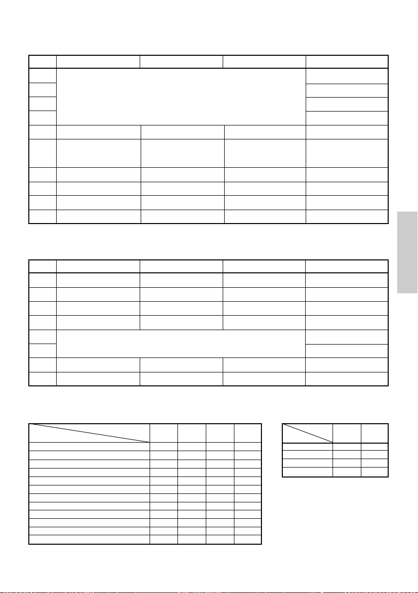
4.2.2 DIP-Schalter 2
Nr. Funktion ON OFF Werkseinstellung
2-1
2-2
2-3
2-4
2-5
2-6
2-7
2-8
2-9 OFFEtikettlänge-Einstellung Befehl Auto
2-10 OFFEtikettenabzieher Verfügbar Nicht verfügbar
* Länderabhängig
Nicht verwendet
Bedingung für BUSY-
Zeichencode (siehe nachstehende Tabelle)
–
Signal
Papier
Detektion Schwarze Markierung Etikettenabstand
Eingangspufferspeicher
voll
Thermo-Etikettpapier
Eingangspufferspeicher
–
Offline und
voll
Thermopapier
OFF*
OFF*
OFF*
OFF*
OFF
OFF
OFF
OFF
4.2.3 DIP-Schalter 3
Nr. ON OFF Werkseinstellung
3-1
3-2
3-3
3-4
3-5
3-6
3-7
3-8
* DIP-Schalter 3 dient nur für die serielle Schnittstelle.
Funktion
Bitlänge
Parität
Ungerade/Gerade
Kommunikationsmodus
Baud-Rate (Siehe nachstehende Tabelle)
DSR Rücksetzung DSR
INIT
7 Bit
Verfügbar
Gerade Zahl
XON/XOFF
Rücksetzung
8 Bit
Nicht verfügbar
Ungerade Zahl
DTR/DSR
—
OFF
OFF
OFF
OFF
OFF
ON
OFF
OFF
DEUTSCH
Wählen der Zeichencodetabellen
Code
Nr.
Code 437 (USA: Europäischer Standard)
Katakana (Japanisch)
Code 850 (Multilingual)
Code 860 (Portugiesisch)
Code 863 (Französisch, Kanada)
Code 865 (Skandinavien)
Code 852 (Osteuropa)
Code 866 (Russisch)
Code 857 (Türkisch)
Windows Code 1252
Nicht definiert
Leerseite
2-1
OFF
ON
OFF
ON
OFF
ON
OFF
ON
OFF
ON
ON
–
2-2 2-42-3
OFF
OFF
OFF
OFF
OFF
ON
OFF
ON
OFF
OFF
ON
ON
OFF
OFF
OFF
OFF
–
ON
— 23 —
ON
ON
ON
ON
ON
Baud-Rate
Nr.
3-5
ON
ON
3-6
OFF
OFF
ON
ON
OFF
OFF
OFF
OFF
OFF
OFF
OFF
OFF
ON
ON
–
–
ON
Baud-Rate
4.800 bps
9.600 bps
19.200 bps
38.400 bps
• „Leerseiten“ sind Bereiche für
Benutzerdefinitionen, die
standardmäßig leer (frei) sind.
• Wird „Katakana“ aktiviert, wird
der internationale Zeichensatz für
Japanisch eingerichtet. Bei Wahl
der anderen Codes erfolgt die
Einrichtung für die USA.
OFF
OFF

5. WARTUNG UND KUNDENDIENST
Für Informationen über Wartung und Kundendienst wenden Sie sich bitte an Ihren
CBM-Händler oder an eine der folgenden Anschriften:
Nordamerika
CBM America Corporation
Service Center
363 Van Ness Way
Suite 404
Torrance, CA 90501, U.S.A
Tel.: +1-310-781-1460
Fax: +1-310-781-9157
E-mail: sales@cbma.com
http://www.cbma.com
Sonstige Länder
Japan CBM Corporation
Information Systems Division
CBM Bldg., 5-68-10, Nakano
Nakano-ku, Tokyo 164-0001, Japan
Tel.: +81-3-5345-7540
Fax: +81-3-5345-7541
E-mail: info-sys@jcbm.co.jp
http://www.jcbm.co.jp
ACHTUNG
• Bei unkorrigierbaren Abbruchfehlern, Rauchentwicklung, Feuer oder anderen
schwerwiegenden Druckerproblemen bitte sofort den laufenden Betrieb abbrechen, den
DEUTSCH
Netzstecker aus der Steckdose ziehen und Kontakt mit einer der oben genannten Stellen
oder Ihrem örtlichen CBM-Händler aufnehmen.
• Versuchen Sie auf keinen Fall, den Drucker selbst zu zerlegen oder zu reparieren.
— 24 —

ITALIANO
ITALIANO
— 1 —

SOMMARIO
1. DESCRIZIONE GENERALE ................................................................... 9
1.1 Caratteristiche ........................................................................................... 9
1.2 Disimballaggio .......................................................................................... 9
2. SPECIFICHE DI BASE ......................................................................... 10
2.1 Categoria modello .................................................................................. 10
2.2 Aspetto esterno e parti componenti ..................................................... 10
2.3 Specifiche di base ................................................................................... 11
2.4 Specifiche carta da stampa e posizione di stampa ............................. 12
2.5 Posizione del sensore e della taglierina ............................................... 13
3. FUNZIONAMENTO ............................................................................. 14
3.1 Collegamento dell’adattatore c.a. e del cavo di alimentazione c.a. ... 14
3.2 Collegamento dei cavi di interfaccia ..................................................... 14
3.3 Collegamento del connettore di apertura del cassetto ....................... 15
3.4 Sistemazione/sostituzione dei rotoli in carta ....................................... 16
3.5 Regolazione del sensore di quasi-fine carta ........................................ 16
3.6 Utilizzo dei rotoli di carta da 58 mm ..................................................... 17
3.7 Rimozione della carta incastrata ........................................................... 17
3.8 Pulitura della testina di stampa ............................................................. 17
3.9 Pannello operativo e segnalazione degli errori ................................... 18
3.10 Stampa automatica .............................................................................. 20
3.11 Copia memoria esadecimale ............................................................... 20
3.12 Buffer di stampa ................................................................................... 21
ITALIANO
3.13 ID del dispositivo .................................................................................. 21
4. IMPOSTAZIONE MICROINTERRUTTORI .......................................... 22
4.1 Posizione dei microinterruttori .............................................................. 22
4.2 Tabella per l’impostazione dei microinterruttori ................................. 22
5. MANUTENZIONE E ASSISTENZA .................................................... 24
APPENDIX 1. OUTLINE DRAWING .......................................................... i
APPENDIX 2. BLOCK DIAGRAM .............................................................. i
APPENDIX 3. IDENTIFICATION OF SEND STATUS ............................... ii
APPENDIX 4. PARALLEL INTERFACE .................................................... iii
APPENDIX 5. SERIAL INTERFACE .......................................................... v
APPENDIX 6. CONTROL COMMAND ................................................... vii
— 2 —

PRECAUZIONI GENERALI
1 Le informazioni contenute in questo documento sono soggette a modifiche
senza preavviso.
2 Tutti i diritti riservati. Nessuna parte di questo documento può essere
riprodotta senza il consenso scritto della CBM Corporation.
3 Salvo diversamente specificato nel presente manuale, non svolgere senza
autorizzazione operazioni di manutenzione, smontaggio o riparazione del
prodotto.
4 La CBM non sarà responsabile per qualsiasi tipo di danno riconducibile al
funzionamento/trattamento non corretto o all’utilizzo in ambienti inadeguati,
non specificati in questo manuale.
5 Azionare la stampante secondo quanto descritto nel presente manuale. La
mancata osservanza delle disposizioni potrebbe essere causa di incidenti o
di altri problemi.
6 I dati sono principalmente destinati ad un utilizzo temporaneo e non
vengono memorizzati per un lungo periodo o in modo permanente. La CBM
non è responsabile per eventuali danni o perdite di profitto derivanti dalla
perdita di dati causata da incidenti, riparazioni, test o altro.
7 In caso di domande o commenti sulle informazioni contenute in questo
manuale, non esitate a contattare il vostro rivenditore CBM.
8 La CBM non è responsabile per eventuali problemi derivati dal
funzionamento della stampante, indipendentemente da quanto indicato al
precedente punto “7”.
ITALIANO
— 3 —

PRECAUZIONI DI SICUREZZA
Prima di utilizzare il prodotto per la prima volta, leggere attentamente le
PRECAUZIONI DI SICUREZZA. Un funzionamento non corretto potrebbe
essere causa di incidenti non previsti (incendi, scosse elettriche o ferite).
● Dopo aver letto il presente manuale, conservarlo in un luogo sicuro e di facile
accesso per l’utilizzo futuro.
● Alcune delle descrizioni contenute in questo manuale potrebbero non essere
rilevanti per alcuni modelli di stampante.
Per evitare il rischio di lesioni ad operatori e a terzi o danni a oggetti, nel
presente manuale vengono usati speciali simboli di avvertenza per indicare
punti importanti che richiedono una stretta osservanza.
● Quanto segue è la descrizione del livello di rischio e di danno che potrebbero
verificarsi se la stampante non viene azionata correttamente, ignorando le
istruzioni fornite dai simboli di avvertenza.
AVVERTENZA
La mancata osservanza delle precauzioni indicate da questo simbolo potrebbe
causare lesioni mortali o gravi.
ATTENZIONE
La mancata osservanza delle precauzioni indicate da questo simbolo potrebbe
provocare lesioni o danni a oggetti.
Questo simbolo viene usato per richiamare l’attenzione su punti
ITALIANO
importanti.
Questo simbolo viene usato per indicare operazioni vietate.
Questo simbolo viene usato per richiamare l’attenzione sul pericolo
di scosse elettriche o di danno elettrostatico.
Questo simbolo denota la necessità di scollegare la stampante dalla
presa a muro.
— 4 —

Etichette di avvertimento
AVVERTENZA
• Non tentare di inserire nel connettore di apertura cassetto
una spina (es. spina modulare) diversa da quella specificata
perché ciò potrebbe danneggiare il collegamento telefonico
o la stampante.
ATTENZIONE
• Immediatamente dopo l’utilizzo, la testina termica rimane
ad una temperatura pericolosamente elevata. Non toccare
la testina fino al suo raffreddamento.
AVVERTENZA
Non utilizzare o depositare questo prodotto in un luogo dove potrebbe essere
esposto a:
• Fiamme o umidità
• Luce solare diretta
• Correnti d’aria calda o radiazioni provenienti da un dispositivo di
riscaldamento
• Ambiente mal ventilato
• Reazioni chimiche in un laboratorio
• Olio, particelle di acciaio o polvere trasportati dall’aria
• Aria salmastra o gas corrosivi
• Elettricità statica o forti campi magnetici
●La mancata osservanza di queste avvertenze potrebbe causare
guasti alla stampante, surriscaldamento, emissione di fumo,
incendio o scosse elettriche.
ITALIANO
Non lasciar cadere oggetti estranei e non versare liquido all’interno
della stampante. Inoltre, non depositare nessun oggetto sulla
stampante.
• Non lasciar cadere nessun oggetto metallico come graffette, punti o
viti all’interno della stampante.
• Non depositare sulla stampante portafiori, vasi o tazze contenenti
acqua.
• Non versare nella stampante caffè, bibite o qualsiasi altro tipo di
liquido.
• Non spruzzare sulla stampante insetticidi o qualsiasi altro liquido
chimico.
●Un oggetto estraneo metallico, se lasciato accidentalmente cadere
nella stampante, può provocare il malfunzionamento della stessa,
incendio o scosse elettriche. Nel caso in cui si verificasse questa
evenienza, spegnere immediatamente la stampante, staccarla dalla presa
di alimentazione e chiamare il rivenditore locale CBM.
— 5 —

Osservare le seguenti precauzioni per la fonte e il cavo di alimentazione:
•
Non collegare o scollegare il cavo di alimentazione con le mani bagnate.
•
Utilizzare la stampante solo con la tensione e la frequenza di alimentazione
specificate.
•
Usare solo l’adattatore c.a. specificato per la stampante.
•
Assicurarsi che la presa di alimentazione alla quale è collegata la stampante
abbia una capacità sufficiente.
•
Non collegare il cavo di alimentazione con polvere o detriti sulla spina ad una presa di
alimentazione.
•
Non alimentare la stampante da una basetta di alimentazione o da una presa di
corrente condivisa con altri apparecchi.
•
Non usare un cavo di alimentazione deformato o danneggiato.
●
L’omissione di una corretta procedura può causare danni alla stampante,
surriscaldamento, emissione di fumo, incendio o scosse elettriche.
●
Un sovraccarico potrebbe provocare il surriscaldamento del cavo di alimentazione
o lo scatto dell’interruttore.
• Non lasciare che nulla si depositi sul cavo di alimentazione. Non
sistemare la stampante in un luogo dove il cavo di alimentazione
potrebbe essere calpestato.
• Non cercare di modificare senza necessità il cavo di alimentazione.
• Non usare o trasportare la stampante con il cavo di alimentazione
piegato, attorcigliato o tirato.
• Non posare il cavo di alimentazione nelle vicinanze di un dispositivo di
riscaldamento.
●
La mancata osservanza di queste precauzioni potrebbe causare la rottura dei fili o
dell’isolamento con conseguenti perdite, scosse elettriche o malfunzionamento della
stampante. Se un cavo di alimentazione viene danneggiato, contattare il rivenditore CBM.
•
Alimentare corrente alla stampante da un’adeguata presa a muro,
facilmente raggiungibile in caso di emergenza.
•
Non lasciare oggetti attorno alla presa di alimentazione per garantire
sempre un facile accesso alla stessa.
●
In caso di emergenza la stampante potrebbe non essere spenta
ITALIANO
immediatamente.
•
Inserire la spina di alimentazione a fondo nella presa.
•
Se la stampante non deve essere utilizzata per un lungo periodo, lasciarla
scollegata dalla sua presa di alimentazione.
Non utilizzare la stampante nei modi seguenti:
•
Non sottoporre la stampante a impatti o sobbalzi molto forti (es. cadute, colpi con
estremità dure).
•
Mai tentare di smontare o modificare la stampante.
•
Non pulire la stampante con un solvente organico quale alcol, diluente di
vernice, triclene, benzene o chetone.
●
L’omissione di una corretta procedura può causare malfunzionamento
Benzine
Thinner
della stampante, surriscaldamento, emissione di fumo, incendio o
scosse elettriche.
Installare, utilizzare o depositare la stampante fuori dalla portata dei bambini.
●
Il contenitore in plastica con il quale viene fornita la stampante deve essere tenuto lontano
dalla portata dei bambini. Se indossato sul capo può provocare il soffocamento.
●
Gli apparecchi elettrici potrebbero provocare lesioni impreviste o incidenti se trattati o
utilizzati non correttamente.
●
Tenere il cavo di alimentazione e i cavi dei segnali fuori dalla portata dei bambini. Inoltre, ai
bambini non dovrebbe essere permesso l’accesso a qualsiasi parte interna della stampante.
— 6 —

ATTENZIONE
Sistemare la stampante su di una superficie piana.
●
In caso contrario essa potrebbe cadere.
Fare attenzione a dove si sistema la stampante e a ciò che viene posizionato accanto ad
essa.
•
Evitare che un muro nelle vicinanze o qualsiasi tipo di tessuto blocchino i fori di
ventilazione della stampante.
•
Non utilizzare la stampante con oggetti depositati su di essa.
●
Fare attenzione alla formazione interna di calore che potrebbe provocare incendi e
deformare la struttura esterna della stampante.
•
Evitare di usare la stampante vicino ad una radio o ad un televisore e non alimentarla
dalla stessa presa utilizzata per questi apparecchi.
•
Per le interconnessioni, utilizzare una coppia di cavi schermati o attorcigliati e nuclei in
ferrite o altri dispositivi antirumore.
•
Evitare di usare la stampante con un dispositivo che rappresenti una forte fonte di
rumore.
●
La stampante potrebbe avere un effetto negativo sulle trasmissioni radio o TV. In
alcuni casi gli apparecchi elettrici potrebbero influenzare in modo negativo la
stampante, causando errori di dati o malfunzionamento.
Usare la stampante con il morsetto di messa a terra collegato ad un adeguato impianto
di messa a terra.
●
Se si verificano dispersioni potrebbe sussistere il pericolo di scosse elettriche.
Non collegare il morsetto di messa a terra della stampante a nessuno di questi impianti:
•
Tubature del gas
●
Potrebbe verificarsi un’esplosione di gas
•
Linea telefonica
•
Aste parafulmine
●
In caso di fulmine, un forte picco di corrente potrebbe provocare incendi o scosse
elettriche
•
Tubazioni idrauliche
●
Tubazioni idrauliche in plastica non dovrebbero essere utilizzate per la messa a
terra. (Possono essere utilizzate solo quelle approvate dall’Acquedotto.)
Prima di collegare o scollegare il cavo di messa a terra alla o dalla stampante,
scollegarlo sempre dalla presa di alimentazione.
Prima di collegare o scollegare il cavo di alimentazione o i cavi d’interconnessione alla o
dalla stampante, spegnere sempre l’unità.
Per scollegare un cavo non afferrarlo mai direttamente. Tenere sempre in mano la spina.
Inserire con decisione la spina del cavo nella presa corrispondente.
●
Una connessione incrociata potrebbe danneggiare la parte elettronica interna della
stampante o l’hardware del sistema host.
Utilizzare la stampante solo con dispositivi che hanno indicato delle specifiche del
solenoide per il connettore di apertura del cassetto.
●
La mancata osservanza di questa precauzione potrebbe provocare un
malfunzionamento o un danno.
ITALIANO
— 7 —

Per evitare possibili malfunzionamenti seguire le seguenti istruzioni:
•
Evitare l’azionamento della stampante senza il rotolo di carta inserito correttamente o
con carta non conforme alle specifiche.
●
Infatti, la testina di stampa potrebbe essere danneggiata o la stampa potrebbe
risultare di scarsa qualità.
•
Evitare l’utilizzo di pezzi di carta strappati o uniti con nastro adesivo.
•
Evitare l’estrazione forzata a mano di carta già inserita.
•
Evitare di incastrare a forza la carta nel coperchio della stampante.
●
La carta potrebbe incepparsi. Per sbloccare, fare riferimento a “Rimozione della
carta incastrata” in questo manuale.
•
Evitare l’utilizzo di uno strumento appuntito e affilato per azionare i tasti del pannello.
●
La mancata osservanza di queste precauzioni potrebbe provocare
malfunzionamenti o danni.
Per evitare il peggioramento delle lesioni e dei danni, seguire le seguenti istruzioni:
•
In caso di problemi non cercare di riparare la stampante.
Affidarla al nostro tecnico specializzato.
•
Non toccare la superficie di stampa della testina termica.
•
Assicurarsi che il coperchio della stampante non imprigioni le mani o le dita.
•
Fare attenzione alle parti affilate della stampante. Evitare lesioni alle persone o danni
agli oggetti.
•
Non toccare nessuna delle parti in movimento (ad es. taglierina, ingranaggi, parti
elettriche attive) mentre la stampante è in funzione.
●
Infatti, ciò potrebbe causare scosse elettriche, bruciature o lesioni.
●
Se dalla stampante provengono fumo, odori strani o rumori inconsueti durante
la stampa, interrompere immediatamente la stampa corrente e scollegare la
stampante dalla presa di alimentazione.
ITALIANO
Per la manutenzione giornaliera, adottare le precauzioni seguenti:
• Durante la pulitura spegnere sempre la stampante e scollegarla dalla presa di
alimentazione.
• Usare un panno soffice e asciutto per pulire la superficie esterna della stampante.
• Per macchie particolarmente difficili, usare un panno soffice leggermente umido.
• Mai usare solvente organico come alcol, diluente per vernici o benzene.
• Mai usare un panno sottoposto a trattamento chimico.
• Per rimuovere pezzetti di carta, usare una spazzola morbida.
• Quando si trasporta la stampante, rimuovere il rotolo di carta dal supporto.
• Durante la pulitura della superficie della testina termica, usare una garza in cotone
leggermente imbevuta di alcol.
ATTENZIONE
•
Non toccare la superficie di stampa della testina termica con le mani nude o con un arnese metallico.
•
Immediatamente dopo la stampa, la testina termica è ad una temperatura pericolosamente elevata.
Prima di iniziare le operazioni di manutenzione consentirne il raffreddamento.
— 8 —
MANUTENZIONE GIORNALIERA
Benzine
Thinner

1. DESCRIZIONE GENERALE
Il modello CBM1000 Tipo II è una stampante termica parallela compatta ideata per
l’utilizzo con un’ampia gamma di terminali per dati, POS (Point of Sale) e cucina.
Dotata di ampie caratteristiche, può essere utilizzata per una vasta serie di applicazioni.
Per ottenere i migliori risultati dalla stampante modello CBM 1000 II , leggere
attentamente le istruzioni contenute in questo manuale.
1.1 Caratteristiche
●
Meccanismo di inserimento della carta. Alimentare/sostituire i rotoli di carta
deponendo semplicemente un rotolo nella stampante e chiudendo il coperchio. Facilita
enormemente la gestione della carta e la pulitura della testina.
●
Facile inserimento della carta e pulitura della testina.
●
Velocità elevata (150 mm/s) e stampa termica silenziosa.
●
Metodo di estrazione della carta fronte-lato. Consente l’installazione della stampante e
l’utilizzo in qualsiasi luogo con poche limitazioni.
●
Struttura ermetica del rivestimento. Evita l’ingresso nella stampante di corpi estranei o
liquidi.
●
Buffer di input integrato.
●
Stampa Barcode (codice a barre). Realizzabile utilizzando comandi speciali.
●
Modalità pagina. Ora è possibile ordinare liberamente le pagine.
●
Registrazione di caratteri definiti dall’utente e di logo nella memoria flash.
●
Interfaccia di apertura cassetto incorporata.
●
Meccanismo automatico di taglio fornito come unità standard.
●
Due tipi di alimentazione di corrente. Scegliere tra un tipo di alimentazione di corrente
incorporato, di facile gestione e un tipo con adattatore c.a. leggero, a nastro.
●
Si possono utilizzare rotoli di carta di larghezza 58 mm impiegando il divisorio fornito.
ITALIANO
1.2 Disimballaggio
Quando si rimuove l’imballaggio della stampante, verificare che siano comprese nella
fornitura le seguenti parti:
Rotolo di carta
campione
Stampante
Divisorio
Adattatore c.a.
(fornito solo con il modello A)
Manuale dell’utente
Cavo di alimentazione c.a.
(non fornito con il modello D)
ATTENZIONE
•
Non utilizzare la stampante in un ambiente in cui si può verificare condensa. Se si forma una
condensa, tenere l’unità spenta fino alla completa evaporazione.
— 9 —
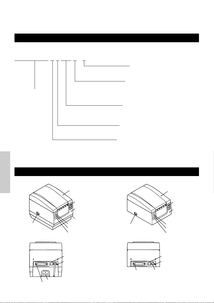
2. SPECIFICHE DI BASE
2.1 Categoria modello
I modelli della stampante sono classificati in base al seguente metodo:
CBM1000 II R F 120 S - L
Funzione carta per etichette
nessuna visualizzazione: Nulla
L: Rilevamento intervallo etichetta
Alimentazione corrente
S: Tipo standard
Denominazione
modello
*Tipo di adattatore dedicato e cavo di
alimentazione:
31AD-U (cavo elettrico a 3 poli 120 V c.a.)
31AD-E (cavo Classe I 230 V c.a.)
2.2 Aspetto esterno e parti componenti
ITALIANO
CBM1000II S CBM1000II A/CBM1000II D
Coperchio della
stampante
Estrattore
Coperchio
superiore
Scatola alimentazione
Interruttore di
alimentazione
Spia di POWER
Spia di ERROR
Interruttore FEED
(Alimentazione corrente incorporata)
A: Tipo adattatore c.a.
D: Senza adattatore c.a.
Specifica cavo di alimentazione allegata
120: Per 120 V c.a.
230: Per 230 V c.a.
024: Senza adattatore c.a.
Serie di caratteri
F: Internazionale
Interfaccia
R: Seriale (RS-232C)
P: Parallela
(conforme IEEE 1284)
Interruttore di
alimentazione
Coperchio della
stampante
Estrattore
Coperchio
superiore
Spia di POWER
Spia di ERROR
Interruttore FEED
Connettore di apertura cassetto
Terminale di messa
a terra
Presa d’ingresso
Connettore interfaccia
— 10 —
Connettore interfaccia
Connettore di
apertura cassetto
Terminale di
messa a terra
Connettore di
alimentazione

2.3 Specifiche di base
Modello CBM1000II RF230S/A
Metodo di stampa
Larghezza di stampa
Densità punti
Velocità di stampa
Numero colonne di
2
stampa*
Dimensione carattere
Pagina codice tipo di
carattere
Registrazione/stampa logo
Tipi di codici a barre
Spaziatura
Rotolo di carta
Rilevamento etichette
Interfaccia
Buffer di input
Tensione di alimentazione
Consumo di corrente
Specifiche adattatore c.a.
Tipo
Peso
Dimensioni esterne
Temperatura e umidità
operative
Temperatura e umidità di
immagazzinamento
Affidabilità
Standard di sicurezza*
3
CBM1000II RF120S/A
CBM1000II PF120S/A
CBM1000II PF230S/A
CBM1000II RF024D
CBM1000II PF024DArticolo
Metodo di stampa termica a righe di punti
72 mm/576 punti, (54 mm/432 punti)*
1
8 × 8 dots/mm (203 dpi)
150 mm/sec (livello standard densità di stampa, più rapido), (1.200 righe di
punti/sec)
1
Font A: 48/42 (36/30)*
Font B: 64/56 (48/40)*
colonne (12 × 24)
1
colonne (9 × 24)
Font A: 1,25 × 3,00 mm; Font B: 0,88 × 3,00 mm
Caratteri alfanumerici, caratteri internazionali, pagine codice PC437, Katakana,
PC850, PC860, PC863, PC865, PC852, PC866, PC857 e pagina codice Windows.
In grado di registrare nella memoria flash caratteri definiti dall’utente e logo.
UPC-A/E, JAN (EAN) 13/8 colonne, ITF CODE 39, CODE 128, CODABAR, CODE
93
4,23 mm (1/6 pollici), selezionabile usando i comandi
Rotolo di carta termica: 80 mm (58 mm) × ø 83 mm
Rotolo di carta termica per etichette: 80 mm (58 mm) × ø 83 mm
(Vedere “Specifiche carta da stampa”.)
Seleziona le Spec.-L (opzione del produttore)
Seriale (RS-232C), Parallela (conforme a IEEE1284, comunicazione bidirezionale)
4K byte (72 byte selezionabili con un microinterruttore)
Tipo S: 120/230 V c.a.±10%; tipo A/tipo D: 24 V c.c.±7%
Circa 100 W
Input nominale: da 120 a 240 V c.a., 50/60 Hz, 120 VA
Potenza nominale: 24 V c.c., 1,9 A (Picco 3,5A)
31 AD-U 31 AD-E
—
—
Tipo S: 2,0 Kg circa; tipo A/tipo D: 1,4 Kg circa
Tipo S: 145 (W) × 190 (D) × 157 (H) mm
Tipo A/tipo D: 145 (W) × 190 (D) × 114 (H) mm
5 da 40°C, da 35 a 85% RH (nessuna condensa)
–20 da 60°C, da 10 a 90% RH (nessuna condensa)
8
Durata testina di stampa: Resistenza agli impulsi 1 × 10
impulsi (rapporto di
stampa 12,5%)
Resistenza all’usura 100 Km (A temperatura/umidità
normale con utilizzo della carta consigliata)
Durata Autocutter: 500.000 tagli (A temperatura /umidità normale con utilizzo
carta consigliata)
UL, C-UL, FCC Classe A TÜV, GS, ContrassegnoCEUL, C-UL, FCC Classe A,
TÜV, GS, Contrassegno
CE
ITALIANO
1
Rappresenta il valore quando viene utilizzato un rotolo di carta da 58 mm (selezionabile dall’utente).
*
2
Il numero di colonne stampabili è selezionabile con un microinterruttore.
*
3
*
È conforme agli standard di sicurezza acquisiti quando vengono usati gli adattatori CBM (serie 31AD).
— 11 —

2.4 Specifiche carta da stampa e posizione di stampa
ø25~28
65~85 µm
(1) Rotolo di carta termica
Larghezza carta 80 +0/-1
Area massima di stampa 72
4422
Larghezza carta 58
Area massima di stampa 54
Unità: mm
(Tipi di carta consigliati)
TF50KS-E2C della Nippon Paper
KP50 della Shin-Ohji Paper
F230AA o HP220A della Mitsubishi
Paper o equivalenti
(2) Foglio etichetta termica (rilevamento intervallo etichetta)
* Solo Spec.-L
Larghezza foglio di base: 80 +0/-1
Largh. Mass. etichetta: 76
Area massima di stampa 72
Larghezza foglio di base: 58 +0/-1
Largh. mass. etichetta: 54
Area massima di stampa 50
Superficie di stampa
ø12
ø18
Ø 83 o inferiore
Superficie di stampa
60~80 µm
Circa 2Circa 2
25
Intervallo minimo etichetta
4
ITALIANO
Unità: mm
Ø 83 o inferiore
etichetta
Lunghezza minima
(Tipi di carta consigliati)
KPT86S/G63BC P22 della Ohji Tac. o
equivalenti
ATTENZIONE
• Una carta a rotolo non conforme alle specifiche potrebbe modificare l’intensità di stampa.
Regolare l’intensità di stampa con il microinterruttore (vedere “Impostazione
microinterruttori”).
• Non incollare l’estremità della carta al centro perché ciò potrebbe causare la colorazione o
lo scolorimento delle lettere se i documenti stampati vengono in seguito a contatto con olio
o sostanze chimiche particolari.
• Lo sfregamento della superficie del documento con le unghie o con un oggetto metallico
potrebbe provocare la colorazione.
• La colorazione si verifica ad una temperatura di circa 70°C o oltre. Tenere i documenti
lontani da fonti di calore, umidità o luce.
— 12 —
60 µm o
inferiore

2.5 Posizione del sensore e della taglierina
Posizione di taglio
manuale
Posizione di taglio
automatico
Riga di stampa
superiore
Circa 27
Circa 13
Sensore di fine
carta
(11mm) (40mm)
Circa 17
Sensore intervallo etichetta
Direzione alimentazione carta
Unità: mm
ATTENZIONE
• Rispettare le seguenti istruzioni per l’utilizzo dell’Autocutter:
• Ogni pezzo di carta non dovrebbe avere una lunghezza inferiore a 10 mm. Strisce di carta
sottili potrebbero provocare l’inceppamento della carta.
• Durante il taglio di un rotolo di etichette, assicurarsi di tagliare il foglio di base. Non
tagliare mai le etichette (cartellini).
ITALIANO
— 13 —
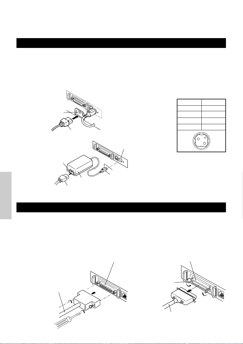
3. FUNZIONAMENTO
3.1 Collegamento dell’adattatore c.a. e del cavo di alimentazione c.a.
1 Spegnere la stampante.
2 Solo per il tipo con adattatore c.a.: Con il lato piatto del connettore del cavo
dell’adattatore c.a. girato verso l’alto, inserire il connettore del cavo nel connettore di
alimentazione sul retro della stampante.
3 Collegare il cavo di alimentazione c.a. nella presa di ingresso della stampante e inserire
la spina del cavo di alimentazione c.a. nella corrispondente presa a muro.
Tipo standard
Presa d’ingresso
Tipo adattatore c.a.
Presa d’ingresso
Cavo di
alimentazione c.a.
Adattatore c.a.
Cavo adattatore c.a.
Connettore di
alimentazione
Lato piatto
Connettore cavo
Connettore utilizzato:
TCS7960-53-2010 (Hosiden) o
equivalente
Connettore applicabile:
TCP8927-63-1100 (Hosiden) o
equivalente
TCP8927-53-1100 (Hosiden) o
equivalente
Configurazione piedini
connettore di alimentazione
No.
1
2
3
SHELL
Funzione
+24
GND
N.C
F. G
1
3
2
ITALIANO
3.2 Connessione cavi interfaccia
1 Spegnere la stampante. (Spegnere altresì il computer host ad essa connesso)
2 Orientare correttamente il terminale del cavo di interfaccia e inserirlo nel connettore
dell’interfaccia.
3 Fissare il terminale del cavo come indicato qui di seguito.
Cavo interfaccia seriale: Fissare il connettore con viti.
Cavo interfaccia parallela: Bloccare il connettore con morsetti.
4 Collegare l’altra estremità del cavo di interfaccia al computer host.
Connettore interfaccia seriale
Cavo interfaccia seriale
Connettore interfaccia parallela
Morsetti
Cavo interfaccia parallela
— 14 —

3.3 Collegamento del connettore di apertura cassetto
1 Spegnere la stampante.
2 Orientare correttamente il connettore del
Connettore di apertura cassetto
cavo di apertura cassetto, inserirlo nel
connettore di apertura cassetto sul retro
della stampante.
3 Fissare con una vite il filo di messa a terra
al connettore di messa a terra sulla
stampante.
Connettore cavo di
apertura cassetto
Conduttore di messa a
terra
ATTENZIONE
• Non collegare cassetti diversi da quello specificato (solenoide) di connettore di apertura
cassetto. (Non collegare neppure una linea telefonica.)
(1) Configurazione piedini connettore
No. Segnale
FG
1
DRAWER 1
2
DRSW
3
VDR
4
DRAWER 2
5
GND
6
Massa
Segnale comando cassetto 1
Input cambio cassetto
Alimentazione corrente comando cassetto
Segnale comando cassetto 2
Messa a terra comune sui circuiti
Funzione
61
(2) Caratteristiche elettriche
1) Tensione di comando: 24 VDC
2) Corrente di comando: Mass. 1 A circa (non dovrà superare i 510 ms.)
3) Segnale DRSW: Livelli segnale: da “L”=0 a 0,5 V, “H”=3 a 5 V
(3) Segnale DRSW
Lo stato del segnale DRSW può essere verificato con i comandi DLE+EOT, GS+a, o GS+r o al
piedino 34 sulla porta dell’interfaccia parallela.
(4) Circuito di comando
1
2
3
4
5
6
VDR
VDR
Connettore utilizzato:
TM5RJ3-66 (Hirose) o
equivalente
Connettore applicabile:
TM3P-66P (Hirose) o
equivalente
ITALIANO
ATTENZIONE
• Durante la stampa non viene prodotto nessun output.
• I cassetti 1 e 2 non possono essere pilotati contemporaneamente.
• Un solenoide utilizzato per il cassetto dovrebbe essere di 24 Ω o superiore. La corrente di
uscita dovrebbe essere mantenuta a 1 A o più bassa; in caso contrario potrebbero
verificarsi danni o svilupparsi fiamme.
— 15 —

3.4 Sistemazione/sostituzione dei rotoli di carta
1 Accendere la stampante.
2 Spingere l’estrattore nella direzione
indicata per sbloccare il coperchio della
stampante.
3 Posizionando le mani su entrambi i lati del
coperchio, aprirlo fino al punto di fermo.
Barra di strappo
Testina di stampa
Coperchio della
stampante
4 Controllare la direzione di avvolgimento
del rotolo di carta e sistemarlo
correttamente nel porta rotolo.
Rotolo di carta
5 Con l’estremità della carta sporgente di
circa 5 cm dalla scatola della stampante,
chiudere il coperchio. Premere
leggermente sul coperchio fino a sentire
Estrattore
uno scatto.
6 Eliminare la carta in eccesso con la barra di
strappo. (Taglierina manuale)
ATTENZIONE
•
Utilizzare sempre i tipi di rotoli di carta specificati.
•
L’impiego di altri tipi di rotoli potrebbe non garantire la qualità di stampa specificata o la durata della stampante.
•
Quando si apre il coperchio della stampante, al raggiungimento della posizione di fermo non applicavi una forza
eccessiva.
•
La testina di stampa diventa calda subito dopo la stampa. Non toccarla con le mani. Durante la stampa, non
aprire il coperchio della stampante. Non trattenere l’estremità della carta durante la fase di stampa e di
estrazione. Infatti, questa operazione potrebbe provocare l’inceppamento della carta.
3.5 Regolazione del sensore di quasi-fine carta
1 Aprire il coperchio della stampante.
2 Spingere la manopola del sensore nella
ITALIANO
direzione della freccia 1 per liberarne la
forcella (o sbloccare l’unità del sensore)
poi regolare l’unità del sensore alla
posizione rimanente di carta desiderata
entro l’intervallo indicato dalla freccia 2.
3 La tabella seguente illustra la relazione tra
le posizioni di regolazione e i livelli di rotoli
di carta rimanenti. (una guida di massima)
Posizione di
regolazione
1
2
3
4
Livello di carta rimanente
(Diametro esterno rotolo di carta/mm)
ø
18
ø
21
ø
24
ø
27
* Quando vengono usati rotoli di carta specificati.
Manopola
sensore
Freccia 1
Freccia 2
Unità
sensore
4321
Posizione di
regolazione
ATTENZIONE
•
Usare il livello di carta rimanente (diametro esterno rotolo di carta) solo come indicazione di massima poiché
esso varia in base alla stampante e ai rotoli utilizzati.
— 16 —

3.6 Utilizzo dei rotoli di carta da 58 mm
1 Spegnere la stampante.
2 Aprire il coperchio della stampante.
3 Estrarre due viti e rimuovere il coperchio
della stampante.
4 Estrarre le viti di fissaggio dello
smorzatore, risistemarlo (11 mm) nella
direzione della freccia, poi bloccarlo
nuovamente con le viti originali.
5 Sostituire il coperchio della stampante.
6 Installare il divisorio fornito in posizione
come illustrato.
7 Cambiare l’impostazione del
microinterruttore per rotoli di carta da 58
mm, facendo riferimento a
“IMPOSTAZIONE MICROINTERRUTTORI”.
Coperchio della
stampante
Smorzatore
Divisorio
ATTENZIONE
• Non cambiare l’impostazione del
microinterruttore da 58 mm a 80 mm nel pieno
della fase di stampa.
3.7 Rimozione di carta inceppata
1 Spegnere la stampante.
2 Aprire il coperchio della stampante.
3 Rimuovere la carta inceppata compresi pezzi di carta residui. (Inoltre, togliere il rotolo
di carta dal supporto.)
4 Chiudere il coperchio della stampante.
5 Accendere la stampante. Il meccanismo Autocutter è inizializzato e l’allarme viene
eliminato.
ITALIANO
ATTENZIONE
• La testina di stampa diventa calda subito dopo la stampa. Non toccarla con le mani. Non
toccare l’elemento di riscaldamento della testina con le mani nude o con un oggetto
metallico.
3.8 Pulitura della testina di stampa
1 Aprire il coperchio della stampante.
2 Eliminare chiazze di polvere e simili sull’elemento di riscaldamento della testina
utilizzando un tampone di cotone imbevuto con alcol etilico.
ATTENZIONE
• La testina di stampa diventa calda subito dopo la stampa. Non toccarla con le mani. Non
toccare l’elemento di riscaldamento della testina con le mani nude o con un oggetto
metallico.
— 17 —

3.9 Pannello di funzionamento e indicazione errori
1 Spia di POWER (verde)
Si illumina quando l’unità è accesa. Lampeggia
quando si è verificato un errore di controllo memoria.
2 Spia ERROR (rossa)
Si accende o lampeggia per indicare differenti tipi di
errore. Lampeggia anche mentre la stampante è in
POWER
ERROR
FEED
Spia di POWER (verde)
Spia ERROR (rossa)
Interruttore FEED
attesa per l’esecuzione di una macro.
3 Interruttore FEED
La breve pressione di questo interruttore consente
l’alimentazione di una riga di carta.
Mentre una macro è in attesa di esecuzione, la
pressione dell’interruttore ne provoca l’esecuzione.
4 Cicalino
Il suono di un cicalino avverte l’operatore di un errore.
Indicazione di errore Spia di POWER Spia di ERROR Cicalino Metodo di ripresa
Errore controllo
memoria
Coperchio aperto Luci Luci
Surriscaldamento
della testina
Quasi-fine carta
Fine carta Luci Luci
ITALIANO
Blocco motore
taglierina
Esecuzione macro
in attesa
Errore bassa
tensione
Lampeggiamento
rapido
Luci
Luci Luci —
Luci
Luci
Luci — Irreversibile
Luci — Irreversibile
(Quattro brevi bip) × 2
Lampeggiamento
lento
Lampeggiamento
rapido e lento
Lampeggiamento
lento
Luci
—
(Quattro brevi bip) × 2
Tre lunghi bip
—
Chiudere il
coperchio.
Riprende automaticamente
quando la temperatura
torna normale.
Posizionare un
nuovo rotolo di
carta.
Posizionare un
nuovo rotolo di
carta.
Rimuovere la carta
inceppata.
Premere
l’interruttore FEED.
Errore alta tensione Luci — Irreversibile
In attesa per azione
taglierina etichette
Attendere l’uscita
etichette
Errore rilevamento
etichetta
Off —
Off —
Off
Lampeggiamento
rapido e lento
Lampeggiamento
lento
Lampeggiamento
lento
Tre lunghi bip
Premere
l’interruttore FEED.
Rimuovere l’etichetta
dal dispositivo di
stacco.
Posizionare il rotolo
etichette
specificato.
— 18 —

Descrizione degli errori
Errore controllo memoria:
Questo errore si verifica se un controllo di lettura dopo la scrittura della memoria o un controllo
dalla somma FROM ha dato come risultato un errore (errore irreversibile).
Coperchio aperto:
Quando si apre il coperchio della stampante, si attiva il sensore di coperchio aperto provocando
l’accensione della spia ERROR e l’arresto delle operazioni di stampa. (Errore irreversibile)
Surriscaldamento della testina:
Per proteggere la testina di stampa dal surriscaldamento, il sensore di temperatura della testina è
attivato se la temperatura raggiunge i 65°C provocando il lampeggiamento della spia ERROR e
l’arresto delle operazioni di stampa. La stampa riprende automaticamente quando la temperatura
della testina scende a circa 60°C. (Errore reversibile automaticamente)
Quasi-fine carta:
Con la progressiva riduzione del diametro del rotolo di carta, il sensore di quasi-fine carta si attiva e
provoca l’accensione della spia ERROR per indicare che l’alimentazione di carta sta diminuendo.
(Vedere “Selecting the paper sensor valid for paper end signal output” e “Selecting the Paper-Near
End Sensor valid for print stop”.)
Fine carta:
Quando il rotolo di carta è finito, il sensore di fine carta situato vicino alla testina di stampa lungo il
percorso di scorrimento della carta rileva la fine del rotolo con la conseguente accensione della spia
ERROR e l’arresto della stampa. (Vedere “Selecting the paper sensor valid for paper end signal
output” e “Selecting the Paper-Near End Sensor valid for print stop”.)
Blocco motore taglierina:
Mentre il motore della taglierina è in funzione, se il sensore di rilevamento della sua posizione
all’interno dell’unità di taglio rimane ON o OFF per circa 1 secondo o oltre, la stampante deduce che
il motore si sia bloccato, provocando l’arresto del funzionamento della taglierina e delle operazioni
di stampa. (Vedere “Rimozione della carta incastrata”.)
Errore tensione bassa:
Si verifica quando la tensione alimentata alla stampante diminuisce; se si è verificata questa
evenienza, spegnere immediatamente l’unità. (Errore irreversibile)
Errore tensione alta:
Si verifica quando la tensione alimentata alla stampante aumenta; se si è verificata questa
evenienza, spegnere immediatamente l’unità. (Errore irreversibile)
In attesa per taglio etichette:
Attendere fino a quando l’etichetta scaricata dal comando GS+FF (taglio etichetta e scarico) viene
tagliata dalla taglierina manuale e viene premuto l’interruttore FEED. Se non vengono selezionate le
funzioni “No Cutter (Nessuna taglierina)” o “No Peeling Mechanism (Nessun meccanismo di
stacco)”, la stampante si posizione in stato Occupata.
Attendere l’espulsione etichette:
Attendere la rimozione dell’etichetta dal foglio di base dopo lo scaricamento con il comando GS+FF
(taglio etichetta e estrazione) (viene selezionata l’opzione di stacco). La stampante diventa
Occupata.
Errore rilevamento etichetta:
Intervalli nelle etichette o segni neri non possono essere rilevati o i fogli delle etichette non
rientrano nei limiti di lunghezza specificati.
Se si verifica un errore di rilevamento dell’etichetta, anche se i fogli usati rientrano nei limiti di
lunghezza specificati, molto probabilmente il sensore o il sistema elettronico periferico sono
difettosi. La stampante diventa Occupata.
ITALIANO
— 19 —

3.10 Stampa automatica
=== Hexadecimal Dump ===
To terminate hexadecimal dump,
Press FEED switch three times.
1
B
40 73 6D 70 6C 65 0A 30 31 32 .@samp l e. 01
33 34 35 36 37 38 39 41 42 43 44 3456789ABCD
45 46 47 48 49 4
A 4B 4C 4D 4F
50 EFGHI JKLMOP
51 52 53 54 55 56 57 58 59 5
A 0D
QRSTUVWXYZ .
61 62 63 64 65 66 67 68 69 6
A 6B
abcd e f gh i j k
6
C 6D 6E 6F
70 71 72 73 74 75 76 lmnopq r s t u v
77 78 79 7
A 0D 0A 0A 0A
wxyz....
=== Completed ===
Quando l’unità è accesa con l’interruttore FEED premuto, la stampante eseguirà una
stampa. Al completamento di tale stampa, la stampante tornerà alle condizioni
normali di funzionamento.
CBM1000
MPV3.xx
LPV3.xx
Serial Interface
Baud Rate : 19200 bps
Data Bit : 8 bits
Parity : None
Handshake : DTR/DSR
Buffer Size
4K bytes
Dip Switches
DS1
1 2 3 4 5 6 7 8
ON o o
OFF o o o o o o
Versioni programma
e caricatore
Interfaccia e relativo
stato (in questo
esempio, seriale I/F)
Dimensioni buffer
Stato
microinterruttore
(DS3 solo per seriale)
DS2
1 2 3 4 5 6 7 8 9 10
ON o
OFF o o o o o o o o o
DS3
1 2 3 4 5 6 7 8
ON o
OFF o o o o o o o
! ”#$ % &’ ( ) *+,–. / 0123456789: ;<=>?@A B C
DEFGHI JKLMNOPQRSTUV
Hi j klm n op qrstuvw xyz{ | }~........
•
•
•
W
X YZ[ \ ] ^_ `abcdefg
Se si usa l’Autocutter, la carta
viene tagliata in pagine dopo la
stampa di ogni pagina.
Vengono stampati tutti
i caratteri stampabili.
3.11 Memoria esadecimale
1 La funzione di memoria esadecimale
consente la stampa in numeri esadecimali
dei dati inviati dal computer host e anche
ITALIANO
in caratteri corrispondenti ai numeri.
2 Avvio memoria esadecimale
Per avviare la copia di memoria
esadecimale accendere la stampante
premendo e mantenendo premuto
l’interruttore FEED con il coperchio della
stampante aperto. Alla chiusura del
coperchio, la stampante prima stampa
“Hexadecimal Dump (Memoria
esadecimale)”, poi stampa tutti i dati
seguenti in forma esadecimale e caratteri.
NOTA
• Se un carattere corrispondente ai dati ricevuti non è disponibile, al suo posto viene
stampato “ . ”.
• Durante l’esecuzione della memoria esadecimale sono attive solo le funzioni DLE EOT e
DLE ENQ.
• Se i dati ricevuti non sono sufficienti per una riga intera, la pressione dell’interruttore FEED
provocherà la stampa della riga.
3 Uscita da memoria esadecimale
La stampante esce dalla modalità di memoria esadecimale se viene spenta, se
l’interruttore FEED è premuto tre volte di seguito o se la stampante riceve un segnale
di ripristino dall’interfaccia, dopo il completamento della memoria esadecimale.
— 20 —
<Esempio di memoria esadecimale>

3.12 Buffer stampante
3.12.1 Buffering
Il buffer della stampante ha una capacità di 4K bite (DS1-6: OFF). L’host viene liberato
immediatamente dopo il trasferimento dei dati alla stampante.
3.12.2 Buffer pieno occupato
Se il buffer della stampante è pieno, il segnale Busy/DTR (Occupato/DTR) è
impostato su “High (Elevato)” per indicare “Buffer full (Buffer pieno)” all’host. La
stampante non è in grado di ricevere dati dall’host con il buffer pieno.
Buffer stampante
4K byte
Busy/DTR Confermato
(Occupato/DTR)
128 byte rimanenti
Busy/Reset DTR (Occupato/DTR)
256 byte rimanenti
72 byte
Nota: Il buffer della stampante può essere inizializzato con DS1-6.
20 byte rimanenti
30 byte rimanenti
3.13 ID dispositivo
Quando la stampante riceve una richiesta di ID del dispositivo dall’host, invia un ID
come indicato qui di seguito, tramite l’interfaccia parallela:
<00>H<31>H
MFG:CBM;
CMD:CBM;ESC/POS;
MDL:CBM1000;
CLS:PRINTER;
I primi due byte dell’ID del dispositivo indicano la lunghezza totale dell’ID compresi
loro stessi.
ITALIANO
— 21 —

4.
IMPOSTAZIONE MICROINTERRUTTORI
4.1 Posizione dei microinterruttori
1 Spegnere la stampante.
2 Aprire il coperchio della stampante.
Coperchio microinterruttore
3 Rimuovere il rotolo di carta e la copertura
del microinterruttore.
4 Dopo aver completato l’impostazione,
rimettere il coperchio nella posizione
originale.
ATTENZIONE
• Non eseguire impostazioni con la
* Il microinterruttore 3 serve
solo per l’interfaccia seriale.
stampante accesa.
4.2 Tabella per l’impostazione dei microinterruttori
4.2.1 Microinterruttore 1
No. Funzione ON OFF
1-1
1-2
1-3
1-4
ITALIANO
1-5
1-6
1-7
1-8
* Sarà differente in base alla impostazione della larghezza della carta (DS1 – 3).
Autocutter
Inutilizzato
Larghezza carta
Colonne di stampa*
Modalità CR
Buffer di input
Densità di stampa (vedere la tabella qui di seguito).
Disponibile
-
58 mm
42 colonne (80 mm)
30 colonne (58 mm)
Funzionamento LF
72 byte
Non disponibile
-
80 mm
48 colonne (80 mm)
36 colonne (58 mm)
Ignorato
4K byte
Densità di stampa
Densità di
No.
Nota: Se la densità di stampa è fissata ad un livello 2 (standard) o oltre, la velocità di stampa potrebbe
diminuire.
stampa
1-7
1-8
Livello 1
(Luce)
OFF
OFF
Livello 2
(Standard)
ON
OFF
Livello 3
(Leggermente scuro)
OFF
ON
Predefinito in stabilimento
ON
OFF
OFF
OFF
OFF
OFF
ON
OFF
Livello 4
(Scuro)
ON
ON
— 22 —

4.2.2 Microinterruttore 2
No. Funzione ON OFF
2-1
2-2
2-3
2-4
2-5
Si sta per verificare la
2-6
condizione per lo stato
BUSY (Occupato).
2-7
2-8
2-9 OFF
2-10 OFFStacca etichette Disponibile Non disponibile
* Dipende dalle destinazioni.
Rilevamento Contrassegno nero Intervallo etichetta
Impostata lunghezza etichetta
Codice carattere (vedere tabella seguente.)
Inutilizzato
Carta
Carta termica per etichette
–
Buffer di ricezione
pieno
Comando Auto
–
Non in linea e buffer di
ricezione pieno
Carta termica
Predefinito in stabilimento
4.2.3 Microinterruttore 3
No. ON OFF
3-1
3-2
3-3
3-4
3-5
3-6
3-7
3-8
* Il microinterruttore 3 serve solo per l’interfaccia seriale.
Funzione
Lunghezza bit
Parità
Dispari/pari
Modalità di comunicazione
Velocità di trasmissione dati (vedere tabella seguente.)
DSR Ripristina DSR
INIZ
7 bit
Disponibile
Numero pari
XON/XOFF
Ripristina
Non disponibile
Numero dispari
8 bit
DTR/DSR
—
Predefinito in stabilimento
OFF*
OFF*
OFF*
OFF*
OFF
OFF
OFF
OFF
OFF
OFF
OFF
OFF
OFF
ON
OFF
OFF
ITALIANO
Selezione delle tabelle del codice carattere
Codice
No.
Codice 437 (USA: Standard Europa)
Katakana (Giapponese)
Codice 850 (Multilingue)
Codice 860 (Portoghese)
Codice 863 (Francese - Canada)
Codice 865 (Nordico)
Codice 852 (Europa Orientale)
Codice 866 (Russo)
Codice 857 (Turco)
Codice Windows 1252
Non definito
Pagina vuota
2-1
OFF
ON
OFF
ON
OFF
ON
OFF
ON
OFF
ON
–
ON
2-2 2-42-3
OFF
OFF
ON
ON
OFF
OFF
ON
ON
OFF
OFF
–
ON
— 23 —
OFF
OFF
OFF
OFF
ON
ON
ON
ON
OFF
OFF
–
ON
OFF
OFF
OFF
OFF
OFF
OFF
OFF
OFF
ON
ON
ON
Velocità di trasmissione dati
Velocità di
trasmissione dati
4.800 bps
9.600 bps
19.200 bps
38.400 bps
•
“Blank page” (Pagina vuota) è
un’area dedicata alla registrazione
dell’utente ed è predefinita come
vuota (con spazio).
•
Quando si seleziona “Katakana”, il
–
carattere internazionale viene
impostato sul Giapponese. Quando
ne vengono selezionati altri, esso
viene impostato su Stati Uniti.
No.
3-5
OFF
ON
OFF
ON
3-6
OFF
OFF
ON
ON

5. MANUTENZIONE ED ASSISTENZA
Per informazioni su manutenzione ed assistenza vi preghiamo di contattare il vostro
rivenditore CBM o i seguenti indirizzi:
America del Nord
CBM America Corporation
Service Center
363 Van Ness Way
Suite 404
Torrance, CA 90501, U.S.A
TEL: +1-310-781-1460
FAX: +1-310-781-9157
E-mail: sales@cbma.com
http://www.cbma.com
Altri paesi
Japan CBM Corporation
Information Systems Division
CBM Bldg. 5-68-10, Nakano
Nakano-ku, Tokyo 164-0001, Japan
TEL: +81-3-5345-7540
FAX: +81-3-5345-7541
E-mail: info-sys@jcbm.co.jp
http://www.jcbm.co.jp
ATTENZIONE
• Se la stampante presenta un errore irreversibile, o se da essa provengono fumo, odori
strani, o si verificano altri problemi, interrompere immediatamente la stampa corrente e
scollegare la stampante dalla presa di alimentazione. Quindi chiamare uno dei centri di
assistenza sopra elencati o il vostro rivenditore CBM.
• Mai tentare di smontare o riparare la stampante.
ITALIANO
— 24 —

ESPAÑOL
ESPAÑOL
— 1 —
 Loading...