

Page 1
3. APPEAR A NC E AN D CONNECTO RS
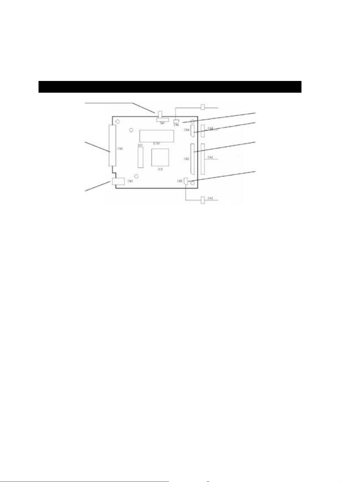
3.1. Appearance
d
Winder
h
f
Operation panel
i
Printer mechanism
e
g
c
PNE sensor
c
DC Jack: Plug the AC ada pter or DC output plu g of t he power supply.
d
Power switch: When this Power switch is turned ON, power is supplied to the board
and initializing operation starts.
e
Connector for mechanism
connection (CN2):
f
Connector for operation
panel (CN4):
a) POWER lamp: Lights when the Pow er switch is set to ON and goes off when the
b) SEL lamp: Lights when this board is in the Select (online) state and goes off when
1) Blinks at intervals of 0.5 s at the occurrence of Paper End.
2) Blinks at intervals of 1/4 s at the occurrence of Alarm state
c) LF switch: Pressing this switch causes a paper feed (only in Deselect state).
d) SEL switch: When this switch is pressed, this board is set to the Select (online)
g
Connector for Paper Near
End sensor (CN5):
Connected t o MD 910 (24 digits) or MD911 (40 digits).
Connected to the operation panel. For the functions, refer to the
following de scriptions.
Power switch is set to OFF.
Blinks while memory switch is set or at the occurrence of memo r y
error.
it is in the Deselect (offline) state. Printing occurs only when this lamp
is ON.
Goes off when the SEL switch is pressed after pa per is set.
(blinking state) due to the cause other than Paper End. This lamp
goes off when the SEL switc h is press ed aft er re movi ng th e cau se
of the alarm or when printer power is reset.
This switch is used when loadi ng a p aper or when using a spac e.
state. Pressing this switch again causes the board to be set to the
Deselect (offlin e) state. This switch is also used when removing the
alarm state. When the printer is set to the Deselect state, all data , if
present in the input buff er, is printed.
Connector for Paper End (paper detection)
Page 2
h
Connector for winder
(CN6):
i Connector for Interface
(CN3):
Connector for connecting Winder (for controlling the motor for auto
paper windin g devic e) (Opt i on )
Either par al lel or serial conn e ctor is present de p ending on the boar d
type.
Connects to each host through a cable. Before connecting the
connector, ma ke sur e the host and board ar e powere d off.
3.2. Connector for Power Supply
Connector used: CN1: MOJ-D14 (Iizuka Electric)
Electrical Specifications
Input volt a ge: 7 to 15 V DC
Current at non printing: 0.15 A average
Current at printing: 0.80 A average (approx. 7.5 A at peak)
The above val u e is at temperature of 25 °C a nd normal humid it y.
Average current is the value with print rate of 12.5%.
The values vary with the printing condition, environment of use, operating conditions, etc.
Precautions
1. Before co nnecting or discon ne cting a connecto r, make sure the prin ter power is turned off.
2. Always use t he power voltage with i n the specified range.
Caution
• When the power supply other than specified is used, bad effect may occu r on printing operation, etc.
When the printer is operated continuously, electronic components in the board may generate heat. Use
the printer pa ying ful l at tent io n to heat dissi pat io n.
• When the power supply with insufficient peak current is used, degradation of print quality may occur
dependi ng on the printing st ate.
• Be sure to prepare for easy tur ni ng off the power sup ply in ca se of power failu re.
• Power supply with var ious kinds of protect ive circui ts such as ove rvolta ge protec tion and ove rcurrent
protection is recommended.
• If any abnormality such as abnormal odor is sensed during operation, turn the power supply off
quickly.
Page 3

3.3. Connecting Mechanism
r
Connector used: CN2: 5267-17A (Molex)
Cord Assy: Set up the con nect io n shown i n the foll owing fi gur e usi ng CA2 (wi th con ne ct or 5264 -1 7).
Control Board Printer Mechanism
DP detecto
Table: Hea d Driving Connector Pin Specifications
Pin No. Signal Name Input/Output Function
1 MOTOR Output Motor drive signal
2 DP Input Photo interrupter emitte r (dot pulse detector)
3 Vccc — Photo interrupter connector (dot pulse detector)
4 LED (–) Output Photo interrupter LED control signal
5 LED (+) — Photo interrupter anode (dot pulse detector)
6 SOL D Output Printing solenoid D drive signal
7 SOL B Output Printing solenoid B drive signal
8 SOL A Output Printing solenoid A drive signal
9 SOL C Output Printing solenoid C drive signal
10 Vp — Power supply for driving
11 SOL H Output Printing solenoid H drive signal
12 SOL F Output Printing solenoid F drive signal
13 SOL E Output Printing solenoid E drive signal
14 SOL G Output Printing solenoid G drive signal
15 PF SOL Output PF solenoid drive signal
Page 4

Pin No. Signal Name Input/Output Function
16 RP (HP) Input Reset pulse switch input signal
17 GND — GND
3.4. Connecting Operation Panel
Connector used: CN4: 5267-06A (Molex)
Cord Assy: Set up the con nect io n shown i n the foll owing fi gur e usi ng CA4 (wi th con ne ct or 5264 -0 6).
Operation Panel Control Board
Table: Operation Panel Pin Specifications
Pin No. Signal Name Input/Output Function
1 Vcc — Power supply for circuits
2 PWR/PE LED Output PWR/PE LED control signal
3 SE L LED Ou tput SE L LED c ontrol signal
4 SEL SW Input SEL SW input signal
5 FEED SW Input FEED SW input signal
6 GND — GND
Caution
(1) Fo r t he POWER and SEL LEDs, a res is tance of 330 Ω is provided at t he circuit side to adjust the
current to 10 mA. Use the LED with forward voltage of about 2 V. Do not use LED exceeding 10
mA. Otherwise, the control may be damaged.
(2) T he input terminals for LF-SW and SEL-SW have the above cir c uit. Though a cerami c capacitor is
inserted in the circuit for preventing chattering, large chattering may occur depending on the switch.
(3) Apply insulati o n processing to th e terminal not in us e to prevent the end of the cable from cont acting
other terminal or parts.
Page 5

3.5. Connecting Paper Near End Sensor
Connector used: CN5: 5267-03A (Molex)
Cord Assy: Set up the con nect io n shown i n the foll owing fi gur e usi ng CA5 (wi th con ne ct or 5264 -0 3).
Sensor Control Board
Table: Paper Near End Pin Specifications
Pin No. Signal Name Input/Output Function
1 PNE PWR — Photo interrupter anode
2 PNE SIG Inpu t Photo interrupter collector
6 G ND — Photo interrupter cathode/emitter
Referen ce Circuit Diagra m
When using photo interrupter
Control Board Photo Interrupter
When using switch
Sensor
GP2S24
Paper
* The above circui t i s an example of refle ct ion type photo interrupter.
When using the above sensor, allow a clearance of approx. 1 mm from paper.
Page 6

As the sensor used is different in electrical characteristics, use the sensor after fully recognizing it.
* The voltage dete ction range of the b o a r d (between 2 and 3) is as fo l lows:
0 to 0.4 V: With paper
1 V or more: Wit hout paper
Detection status other than the above is out of warranty.
3.6. Connecting Winder
Connector used: CN6: B2B-XH-A (JST9
Set up the co nnection shown in th e f ollowing figur e.
Voltage for the winder motor is applied at the same timing as that for the motor for printer mechanism.
Printin g deviation may be cause d by the torque of windin g.
Winder Connection
Example
Control Board WINDER (AW-5)
 Loading...