

Page 1

CITIZEN
Service Manual
Model: CBM1000
Line Thermal Printer
Rev. 1.00 Newly issued on Sep. 14. 1999
Ja
Jappppaaaan
JaJa
IIIInnnnffffoooorrrrmmmmaaaattttiiiioooon
n CCCCBBBBM
n n
M CCCCoooorrrrppppoooorrrraaaattttiiiioooonnnn
M M
n SSSSyyyysssstttteeeemmmms
n n
s DDDDiiiivvvv....
s s
Page 2

CBM1000 Service Manual
IIIINNNNTTTTRRRROD
ODUUUUCCCCTTTTIIIIOOOONNNN
ODOD
This manual describes the disassembly, reassembly, and maintenance procedures of the line
thermal printer CBM1000. It is intended for field maintenance men.
FFFFEEEEAAAATTTTUUUURRRREEEESSSS
The CBM1000 is a compact-siz ed, line t herma l print er de velo pe d for a variety of a pplic atio ns. It
has abundant built -in fea tures, and ca n be used as a data comm unicat ion term inal, POS term inal,
kitchen terminal and for other applications. Prio r to using the printer, read this manual thoroughly to underst and its contents.
1. Paper drop-in mechanism; when supplying or replacing paper rolls, all you have to do is just
drop a paper roll into the printer and close its cover. This will facilita t e paper handling and
head cleaning greatly.
2. High speed (100 mm/s), and low-noise thermal printing.
3. Front-side paper ejection method, which allows the printer to be installed and used anyw here
with few restrictions.
4. Hermetic covering structure, which helps prevent any foreign matter or liquid from getting
into the printer.
5. Built-in input buffer.
6. Bar-code printing (Possible using special commands).
7. Page mode, which allows you to lay out pages freely.
8. Registration of user-def ined characters and logos into flash mem o ry.
9. Built-in Drawer Kick-Out interface.
10. Auto cutter mechanism provided as a standard unit.
11. Selection possible, as required, from two types: Easy-to-handle, built-in power supply type,
and lightweight f lat AC adapter type.
12. Use of 58 mm wide paper rolls possible by using the partition supplied.
2
–
–
CITIZEN
Page 3

CBM1000 Service Manual
CCCCOOOONNNNTTTTEEEENNNNTTTTSSSS
1. HANDLING AND MAINTENANCE OF PRINTER ..........................................................................5
2. SPECIFICATIONS...............................................................................................................................6
2.1 Basic Specifications ....................................................................................................................6
3. DISASSEMBL Y AND REASSEMBL Y ................................................................................................7
3.1 Disassembly Procedure...............................................................................................................8
3.1.1 Disassembly Procedure for Main Body.........................................................................8
3.1.2 Disasse mbly Procedure for Mechanism Unit.............................................................12
3.2 Reassembly Procedure..............................................................................................................17
3.3 Lubrication ................................................................................................................................18
3.3.1 Lubricant.......................................................................................................................18
3.3.2 Where to Lubricate.......................................................................................................18
4. TROUBLESHOOTING ......................................................................................................................19
4.1 Troubleshooting Procedure..………………………………………………………………..………19
4.2 T roubleshooting Guide.. ..…………………………………………………………………….……..19
5. SERVICE PARTS LIST......................................................................................................................23
5.1 Parts List for Mechanism.........................................................................................................23
5.2 Disassembly Drawing...............................................................................................................25
5.3 Parts List for Control PCB Assy .............................................................................................27
5.3.1 Control PCB Assy ......................................................................................................27
5.4 Parts Layout Drawing ..............................................................................................................30
5.4.1 Control PCB Assy (Serial Interface D-sub 25)............................................................30
5.4.2 Control PCB Assy (Parallel Interface) ........................................................................31
5.4.3 Operation PCB Assy.....................................................................................................32
5.4.4 Sensor PCB Assy...........................................................................................................33
5.4.5 PNE PCB Assy in PNE Lever Assy.............................................................................34
6. DRAWING...........................................................................................................................................35
6.1 Block Diagram..........................................................................................................................36
3
–
–
CITIZEN
Page 4

CBM1000 Service Manual
6.2 Circuit Diagram ........................................................................................................................37
6.2.1 Control PCB Assy (Serial Interface D-sub 25)............................................................37
6.2.2 Control PCB Assy (Parallel Interface) ........................................................................38
7. OUTER DIMENSION .............................................................................................................. ..........39
For the auto cutter unit (ACS-130), see the separate Service Manual.
T
4
–
–
CITIZEN
Page 5

CBM1000 Service Manual
1111....H
HHHAAAANNNNDDDDLLLLIIIINNN
See the User’s Manual coming with the printer body.
NG
G AAAANNNND
G G
D MMMMAAAAIIIINNNNTTTTEEEENNNNAAAANNNNCE
D D
CE OOOOF
CE CE
F PPPPRRRRIIIINNNNTTTTEEEERRRR
F F
5
–
–
CITIZEN
Page 6
CBM1000 Service Manual
2222....SSSSPPPPEC
2222....1111BBBBaaaassssiiiic
ECIIIIFFFFIIIICCCCAAAATTTTIIIIOOOONNNNSSSS
ECEC
c SSSSppppeeeecccciiiiffffiiiiccccaaaattttiiiioooonnnnssss
c c
Item
Model
CBM1000
CBM1000
–
RF120S/A
–
PF120S/A
CBM1000
CBM1000
–
RF230S/A
–
PF230S/A
CBM1000
CBM1000
–
RF024D
–
PF024D
Printing system Line thermal dot printing method
Printing width 72 mm/576 dots, (54 mm/432 dots) *
1
Dot density 8 × 8 dots/mm (203 dpi)
Printing speed 100 mm/sec (Fastest, print density level 2), (800 dot lines/sec)
Printing columns
Font A: 48/42/36/30 columns (12 × 24)
Font B: 64/56/48/40 columns (9 × 24)
Character size Font A: 1. 25 × 3. 00 mm; Font B: 0.88 × 3.00 mm
Character types Alphanumeric characters, unternational characters, Codepages PC437,
Katakana, PC850, PC860, PC863, PC865, PC852, PC866, PC857, and
Windows codepage
Logo registration/ print
Bar code type s
Capable of register ing user-defined characters and logos into flash mem-
ory.
UPC-A/E, JAN(EAN) 13/8 column, I TF, CODE 39, CODE 128, CODE-
BAR, CODE 9 3
Line spacing 4.23 mm (1/6 inch); sel e ct able using commands.
Paper Thermal paper roll: 80 mm (58 mm) × ø83
Interface Serial (RS-232C)
Parallel (IEEE 1284 and Centronics compliant)
Input buffer 4K bytes (72 bytes selectable with a DIP switch)
Supply voltage S type: AC 120/230 V ±10%; A type/D type: DC 24 V ±7%
Power consumption 100 W (Max.)
AC adapter spec. Rated input : AC 120 ~ 240 V, 50/60 Hz, 120 VA
Rated output: DC 24 V, 1.9 A
—
Type 31AD-U 31AD-E —
Weight S type: Approx. 2.0 Kg; A type/D type: Approx. 1.4 Kg
Outer dimensions S type: 145(W) × 190 (D) × 157 (H) mm
A type/D type: 145(W) × 190 (D) × 114 (H) mm
Operating temperature
5 ~ 40ºC, 35 ~ 85 % RH (No dew condensation)
and humidity
Storage temperature
-20 ~ 60ºC, 10 ~ 90% RH (No dew condensati on)
and humidity
Reliability Printing head life:
Pulse resistance: 1 × 10
8
pulses (Print ratio 12.5%)
Wear resistance: 100 km (At normal temperature/humidity with re-
commended thermal paper)
Auto cutter life:
500,000 times of cutting (At normal temperature/humidity with recommended thermal paper)
Safety Standard *
2
UL, C-UL, FCC Class-A
TUV, GS, CE marking
UL, C-UL, FCC
Class-A, TUV, GS,
CE marking
*1 Represents the value when a 58 mm wide paper roll is used (User selectable).
2
*
Represents the safety standards acquired when CBM-made adapters (31AD series) are used.
6
–
–
CITIZEN
Page 7

CBM1000 Service Manual
3333....D
ASS
DDDIIIISSSSAAA
For maintenance operat ions, note the following:
Notes:
(1) Do not disassemble/reassemble or adjust the machine, if it functions properly. Particularly,
(2) After completing an inspection and before turning on the power, be sure to check that there is
(3) During maintenance, be careful not to leave parts or screws unattached or loose inside the
(4) When handling the thermal head or electronic component, do not use gloves or other aids
(5) When disassembling or reassembling, check wires and cables for any damage. Do not run
(6) After reassembling, apply lubricant as required.
MMMMaaaaiiiinnnntttteeeennnnaaaannnncccceeee TTTToo
(1) Philips screwdrivers #1 and #2
SSEEEEMMMMBBBBLLLLY
SSSS
do not loosen screws on any component, unless necessary.
no abnormality.
printer.
which can easily cause static electricity.
them into a narrow space o r set t hem in improper positions.
Y AAAANNNND
Y Y
oollllssss::::
oooo
D REA
REASS
D D
REAREA
SSEEEEMMMMBBBBLLLLYYYY
SSSS
(2) Tweezers
(3) Round nose pliers
(4) Cutting nipper
(5) Brush for lubrication
7
–
–
CITIZEN
Page 8
CBM1000 Service Manual
3333....1111D
DDDiiiissssaaa
ass
sseeeemmmmbbbblllly
ssss
y PPPPrrrroooocccceeeedddduuuurrrreeee
y y
Disassembly procedure consists of the following two sections.
• Main body
• Mechanism
3333....1111....1111D
DDDiiiissssaaa
ass
sseeeemmmmbbbblllly
ssss
y PPPPrrrroooocccceeeedddduuuurrrreeee ffffoooor M
y y
r Maaaaiiiin
r Mr M
n BBBBooooddddyyyy
n n
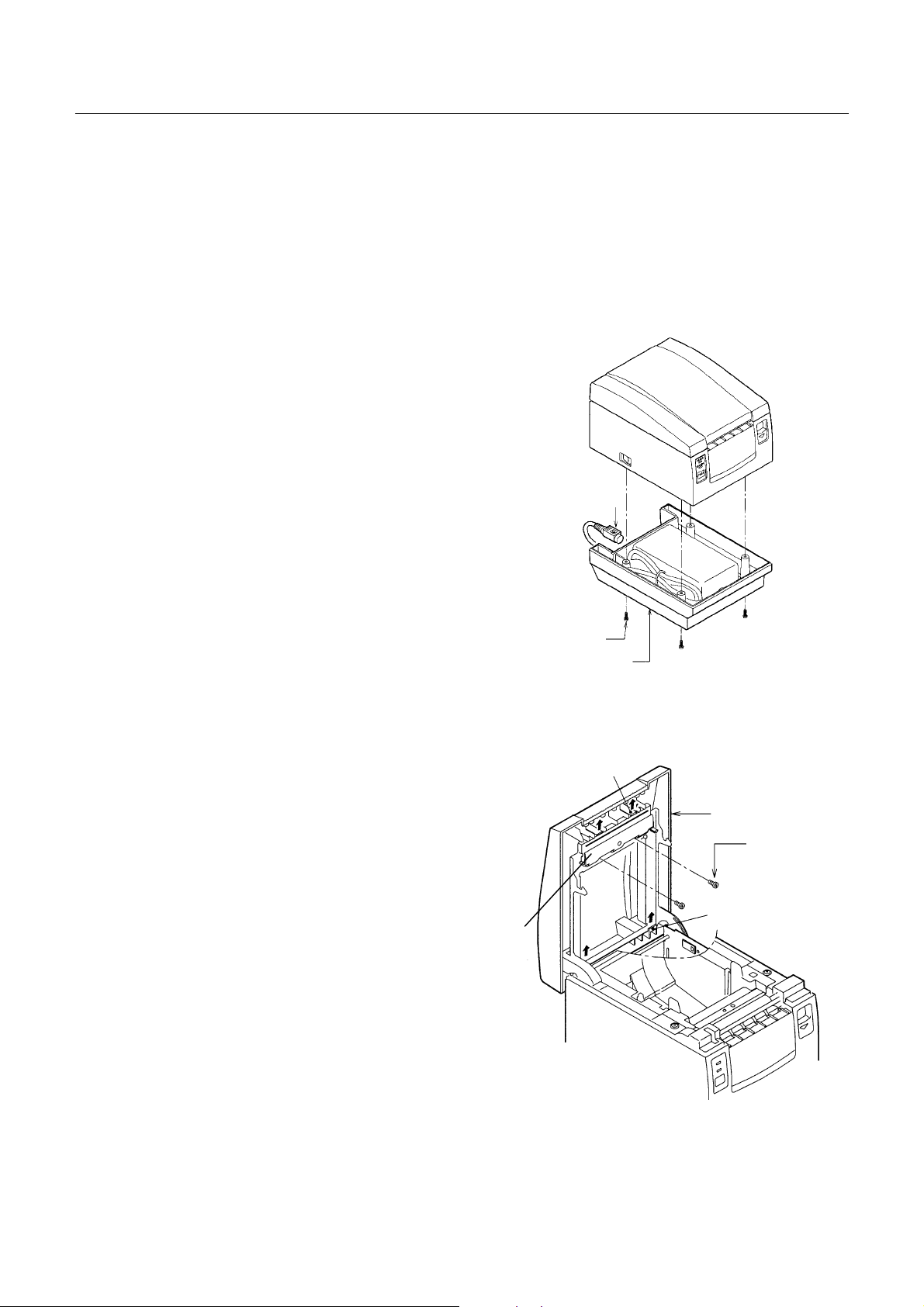
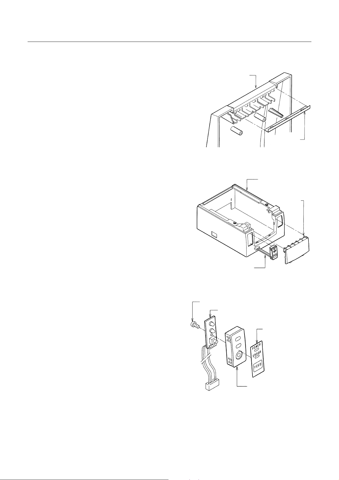
1. Removing the Power Case SA (for AC Adaptrer Built-in Type)
(1) Disconnect the power connector from
the unit.
(2) Remove the four screws M3 ×8 (ST)
and detach the powe r c ase SA.
Power Connector
2. Removing the Printer Cover SA
(1) Open the printer cov e r S A.
(2) Unhook the parts “A” and detach the
printer cover SA.
(3) Remove the two screws M3 × 8 (BT).
While opening the parts “B”, remove
the par t “C”.
×
M3
8 (ST)
Power Case SA
C
B
Printer Cover SA
×
8 (BT)
M3
A
8
–
–
CITIZEN
Page 9
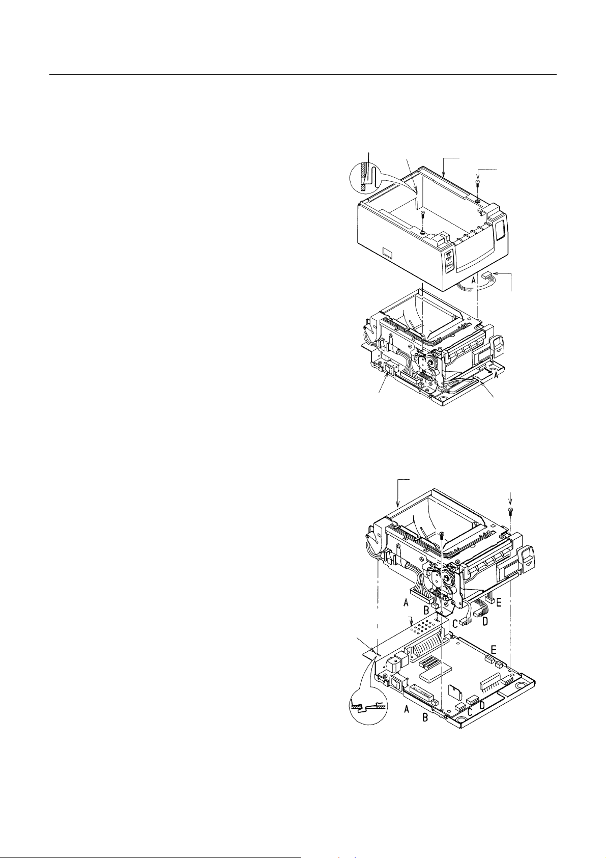
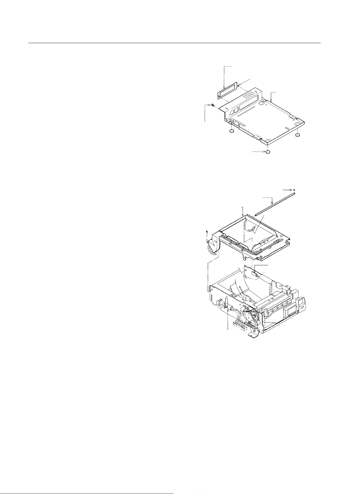
3. Removing the Top Cover SA
(1) Remove the printer cover SA.
(2) Remove the two screws M3 × 6 (ST).
While unhooking the part “B” of the
frame from the top cover SA, lift the top
cover. At this time, avoid the power
switch.
(3) Unhook the operation panel cable from
the cable holder, disconnect the operation panel connector from the control
PCB assy, and remove the top cover SA.
Note on reassembling:
When reassembling the top cover SA,
B
CBM1000 Service Manual
Square Hole
Top Cover SA
M3×6 (ST)
Operation Panel
Connector
be sure that the part “B” of the frame is
securely inserted into the square hole
at the back of the top cover SA as
shown in the figure.
4. Removing the Mechanism Unit
(1) Remove the top cover SA.
(2) Remove the two screws M3 × 6 (ST).
(3) Disconnect the five connectors “A to E”
from the control PCB a ssy.
(4) Lift the front part of the mechanism
unit a little and remove the mechanism
unit by disengaging it from two square
holes on the bottom chassis.
Power Switch
Bottom Chassis
Square Hole
Cable Holder
Mechanism Unit
M3
×
6 (ST)
9
–
–
CITIZEN
Page 10
CBM1000 Service Manual
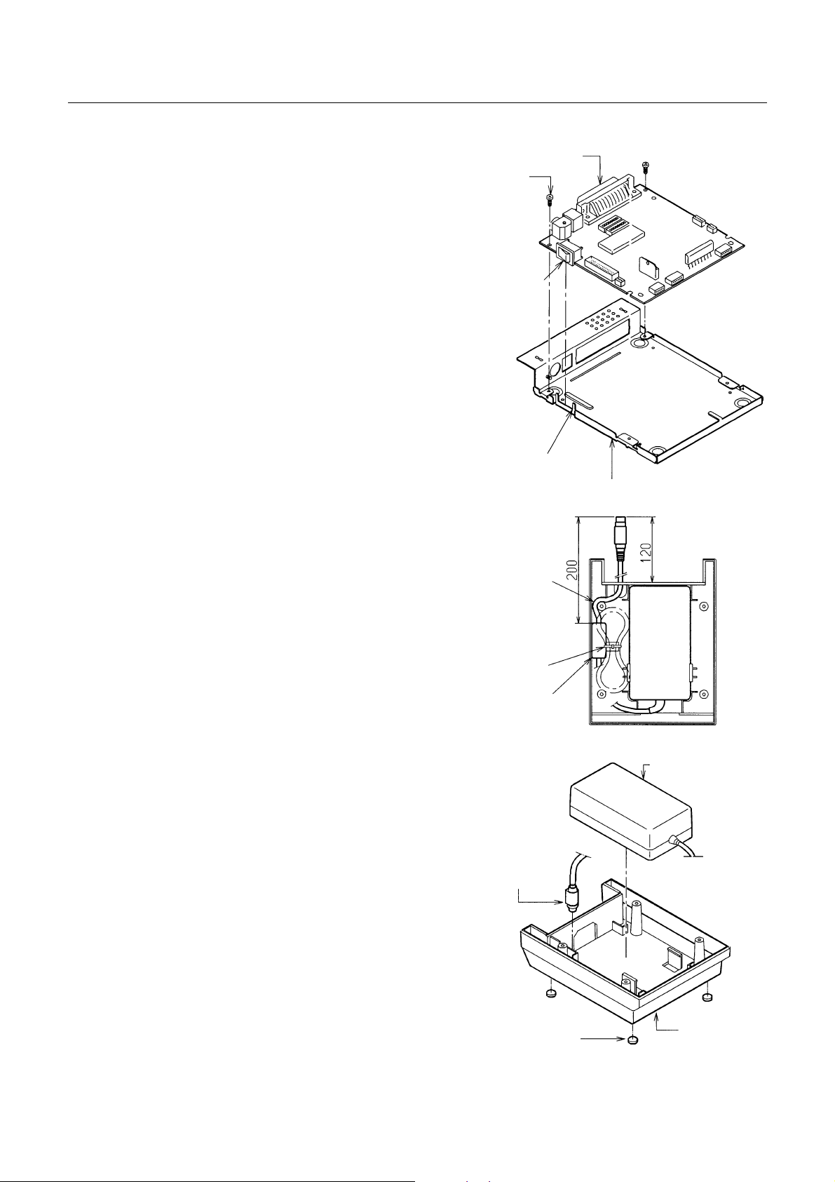
5. Removing the Control PCB Assy
(1) Remove the mechanism unit.
(2) Remove the two screws M3 × 6 (ST).
(3) Lift the front part of the control PCB
assy to disengage the power switch
from the switch guide of the bottom
chassis SA.
Then pull the control PCB assy toward
you to remove it.
6. Removing the AC Adapter
(1) Remove the power case SA.
Control PCB Assy
M3×6 (ST)
Power Switch
Switch Guide
Bottom Chassis SA
(2) Cut the tie for the power cord.
(3) Detach the AC adapter from the power
case by lifting it upward.
(4) Detach the power cord of the AC adap-
ter from the power case SA.
(5) Remove the power connector of the AC
adapter by passing it through the hole
on the power case SA.
(6) Remove the four rubber feet from the
power case.
Note on reassembling:
Run the cable of the AC adapter as
shown in the figure. At this time, run
it so that the ferrite core is located as
shown in the figure (approx. 200 mm
from the end of the power connector).
Cord is fixed.
Tie
Ferrite Core
AC Adapter
Power
Connector
Rubber Foot
10
–
–
Power Case
CITIZEN
Page 11
7. Removing the Tear Bar
(1) Open the printer cov e r.
(2) Remove the tear bar from the printer
cover SA by pulling it as shown in the
figure.
Note on reassembling:
When reassembling, press-fit it to the
CBM1000 Service Manual
Printer Cover
printer cover.
8. Removing the Operat ion Panel SA and Front Cover
(1) Remove the top cover.
(2) Remove the operation panel SA to the
front by pushing its back.
(3) Remove the front cover.
9. Removing the Operat ion PCB Assy
(1) Remove the operation pane l SA.
(2) Remove the one screw M2.6 × 6 (BT)
Tear Bar
Top Cover
Front Cover
Operation Panel SA
M2.6×6 (BT)
Operation PCB Assy
and detach the operat ion PCB assy.
(3) Peel off the operation sheet from the
operation panel.
11
–
–
Operation Sheet
Operation Panel
CITIZEN
Page 12
CBM1000 Service Manual
10. Removing the Serial IF Plate
(1) Remove the control PCB as sy.
(2) Straighten the projections of the serial
IF plate and remove it from the bottom
chassis SA. (For serial IF type)
(3) Remove the one screw M3 × 6 for frame
ground (FG) and rubber feet from the
bottom chassis.
3333....1111....2222D
DDDiiiissssaaa
ass
sseeeemmmmbbbblllly
ssss
y PPPPrrrroooocccceeeedddduuuurrrreeee ffffoooor M
y y
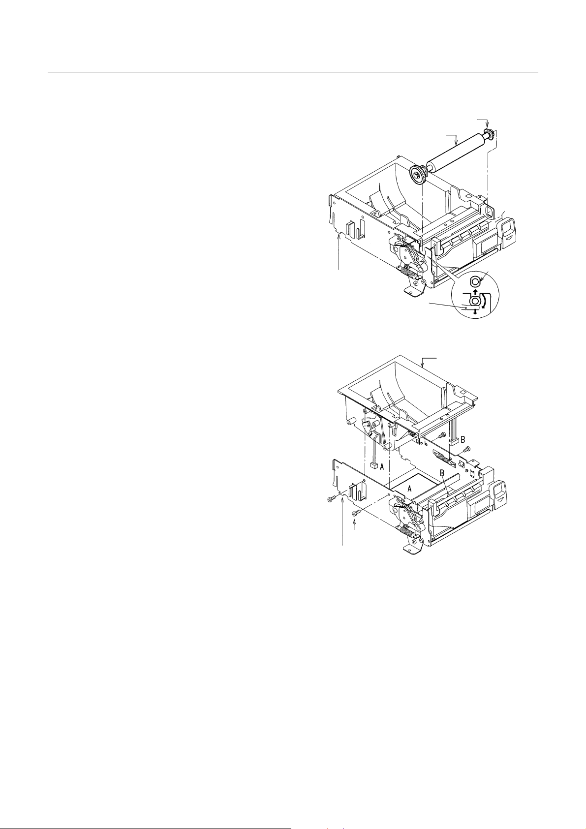
1. Removing the Top Chassis SA
(1) Remove the Mechanism Unit referring
to 3.1.1-4 “Removing the Mechanism
Unit”.
(2) Unhook the head cable assy.
r Meeeecccchhhhaaaannnniiiissssm
r Mr M
m UUUUnnnniiiitttt
m m
×
M3
(ST, EXT, TW)
6
Rubber Foot
Top Chassis SA
Top Chassis SA
Serial IF Plate
Projection
Bottom Chassis
E-Ring, 2
Chassis Shaft
Brake Disc
(3) Disengage the E-ring 2 at the left end
of the chassis shaft.
(4) Pull out the chassis shaft to the right.
(5) While disengaging the projection of the
brake from the brake disc of the top
chassis SA, remove t he top chassis SA.
Brake
Head Cable Assy
12
–
–
CITIZEN
Page 13
CBM1000 Service Manual
2. Removing the Platen SA
(1) While pushing the pressure arm
downwardly, turn the platen bushing
by 90 degrees in either direction.
(Then, the flat surfaces of the left side
platen bushing are set in vertical.)
(2) Lift the left side platen SA to disengage
it from the U-shaped groove on the
main chassis.
(3) Pull the platen SA to the left to remove
it from the main chassis.
3. Removing the Center Frame SA
(1) Remove the four screws M3 × 6 (BT).
(2) Remove the center frame SA from the
main chassis by lifting it upward.
Main Chassis
Pressure Arm
Platen Bushing
Platen SA
Center Frame SA
Center Frame SA
Flat Surface
Note on reassembling:
Pass the connector A and B through the
holes A and B on the main chassis, respectively.
M3×6 (BT)
Main Chassis
13
–
–
CITIZEN
Page 14

CBM1000 Service Manual
4. Removing the Gears
(1) Remove the two screws M3 × 6 (ST)
and remove the gear holder.
(2) Remove the reduction gear and idle
gear from the gear holder, in that order.
Note on reassembling:
Apply grease (Molykote EM-10L) to the
shafts of the gear holder.
5. Removing the Auto Cutter SA
(1) Remove the four screws M3 × 6 (ST)
and remove auto cutter SA.
Main Chassis
Idle Gear
Reduction Gear
Gear Holder
M3×6 (ST)
Auto Cutter SA
Main Chassis
6. Removing the Lock Lev ers
(1) Remove the EXT spring-01.
(2) Pull out the ejector.
(3) Remove the lock lever-R-SA from the
right end of the lock lever-L-SA.
(4) Remove the lock lever-L-SA by pulling
it to the left.
M3×6 (ST)
EXT Spring-01
Main Chassis
Lock Lever-L-SA
14
–
–
Lock Lever-R-SA
Ejector
CITIZEN
Page 15

7. Removing the Pressure Arms
CBM1000 Service Manual
(1) Disengage the EXT spring-01 from the
pressure arm-L and then remove the
pressure arm-L from the main chassis.
(2) Disengage the EXT spring-01 from the
pressure arm-R and then remove the
pressure arm-R from the m ain chassis.
(3) Remove the one screw M3 × 6 (ST) from
the main chassis.
Note on reassembling:
Securely insert the pressure arm-L/R
into the screw heads.
8. Removing the Stepping Motor and Brake
(1) Remove the two screws M3 × 4 and de-
tach the stepping motor .
(2) Remove the one screw M3 × 6 (ST) and
Main Chassis
Main Chassis
Pressure Arm-R
M3×6 (ST)
EXT Spring-01
Pressure Arm-L
M3×6 (ST)
Brake
detach the brake.
Notes on reassembling:
Reassemble the brake in the direction
shown in the figure.
When reassembling t he ste pping m otor,
position it so that its cable runs downward as shown in the figure.
M3×4
Stepping Motor
15
–
–
CITIZEN
Page 16

9. Removing the Top Chassis SA
CBM1000 Service Manual
(1) Unhook the head cable assy from the
cable holder.
(2) Detach the wire.
(3) Remove the two screws M2.6 × 6 (BT)
and detach the head cover.
(4) Remove the two screws M3 × 4 and de-
tach the thermal head. Then, discon-
nect the two connectors from the ther-
mal head.
(5) Remove the head cable assy by passing
its connectors A and B from the holes A
and B on the top chassis.
(6) Remove the one screw M3× 6 (BT) and
detach the damper block.
(7) Remove the roller from the damper.
10. Removing the Platen
(1) Disengage the two E-ring 4 from both
ends of the platen shaft.
Top Chassis
Cable Holder
Thermal Head
Head Cable Assy
M3×6 (ST)
Damper
M2.6×6 (BT)
M3×4
Roller
Head Cover
Wire Cover
Head Cover
Platen Bushing
E-Ring, 4
(2) Pull out platen gear from the left side
platen bushing.
(3) Pull out both platen bushings and dis-
engage the two E-ring 4 from the
platen.
Notes on reassembling:
Insert the two platen bushings so that
their flat surfaces face inw ard.
When inserting the platen gear, align
its hole with the D-cut on the platen
shaft.
Platen
Platen Gear
16
–
–
CITIZEN
Page 17

11. Removing the Center Frame
(1) Remove the PNE lever assy, sensor
plate, guide roller and DIP SW cover
block.
CBM1000 Service Manual
Slider
DIP SW Cover
(2) Remove the one screw M2.6 × 6 (BT)
and detach the sensor PCB assy.
(3) Remove the slider from the DIP SW
cover.
Note on reassembling:
When reassembling the sensor PCB
assy, hook its one end and then install
it with the screw.
12. Removing the Auto Cutter and Its Peripheral Parts
(1) Remove the two screws M3 × 4 an d pull
out the auto cutter in the direction
shown by the arrow.
(2) Pull out safety cover shaft from the cut-
Auto Cutter
ter plate and safety cover.
Sensor Plate
PNE Lever Assy
Safety Cover
Center Frame
Guide Roller
×
M2.6
Sensor PCB Assy
Cutter Plate
M3×4
6 (BT)
(3) Remove the EXT spring-03.
(4) Detach the safety cover from the cutter
plate.
EXT Spring-03
Safety Cover Shaft
3333....2222RRRReeeeaaaasssssssseeeemmmmbbbblllly
y PPPPrrrroooocccceeeedddduuuurrrreeee
y y
Reassemble each part in t he reverse or der of the disa ssembly procedure descri bed in Sect ion 3.1.
If notes on reassembl ing are written, follow them.
17
–
–
CITIZEN
Page 18

3333....3333LLLLuuuubbbbrrrriiiiccccaaaattttiiiioooonnnn
Apply the specified lubricant to the indicated places.
3333....3333....1111LLLLuuuubbbbrrrriiiiccccaaaannnntttt
Grease: Molykote EM-10L
CBM1000 Service Manual
3333....3333....2222W
WWWhhhheeeerrr
A. Platen bushings and the platen shafts (2 places each)
B. Gear shafts of the gear holder (2 places)
C. Sliding surface of the brake disc
D. Lock shaft parts of the lock lever-R/L (2 places on both sides)
E. Sliding parts of the pressure arm-R/L (3 places on both sides)
F. U-shaped grooves of the main chassis, where the platen bushings are engaged (2 places
re
e tttto
o LLLLuuuubbbbrrrriiiiccccaaaatttteeee
e e
o o
(See the following figure.)
(See the following figure.)
on both sides)
(See the following figure.)
18
–
–
CITIZEN
Page 19

CBM1000 Service Manual
4444....TTTTRRRROOOOUUUUBBBBLLLLEEEESSSSHHHHOO
4444....1111TTTTrrrroooouuuubbbblllleeeesssshhhhoo
When a trouble occurs, confirm its phenomenon, locate a defective part in accordance with 4.2
Tro ub leshooting Guide, and troubleshoot a s des cribed below.
Phenomenon: Find a trouble phenomenon in this column. If there are multiple
l
Cause: Lists as many possible causes as possible. Guess a trouble cause out
l
Check Method: Describes a check method to specify a trouble cause.
l
Remedy: Tro ubleshoot by taking a remedy described in this column.
l
By troubleshooting in accordance with the above-mentioned procedure, you can troubleshoot efficiently with fewer misjudgments.
4444....2222TTTTrrrroooouuuubbbblllleeeesssshhhhoo
PPPPoooowwwweeeer
r SSSSuuuupp
llll
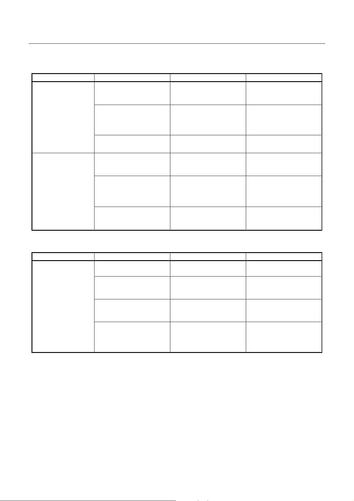
Phenomenon Cause Check Method Remedy
No power
(POWER lamp not
illuminated)
The fuse immediately goes again
after replacing with
new one.
pplllly
r r
pppp
oottttiiiinnnng
oooo
oottttiiiinnnng
oooo
y FFFFaaaail
iluuuurrrreeee
y y
ilil
OOTTTTIIIINNNNGGGG
OOOO
g PPPPrrrroooocccceeeedddduuuurrrreeee
g g
phenomena, take all the corresponding items into consideration.
This allows you to s pecify a hidden defect iv e part.
of them and take its check method to specify the trouble cause.
g GGGGuuuuiiiiddddeeee
g g
The AC adapter is not
connected.
The fuse is gone.
The control PCB assy is
defective.
The circuit drive power
is abnormal.
Check whether any unspecified power has
been used so far.
Check whether the
specified fuse is used.
With a DC voltmeter,
measure the circuit
drive voltage.
Connect the specified
AC adapter.
Use the specified AC
adapter.
Use the specified fuse.
Replace the control P CB
assy.
Replace the control P CB
assy.
If the fuse is gone with the specified AC voltage supplied to the AC adapter, it is likely that the
T
thermal head unit or control PCB assy is defective. Replace either defective one. Incidentally,
check the wiring of the drawer an d interface cable.
19
–
–
CITIZEN
Page 20

CBM1000 Service Manual
PPPPrrrriiiinnnnttttiiiinnnng
llll
No printing
g ffffaaaaiiiilllluuuurrrreeee
g g
Phenomenon Cause Check Method Remedy
Faulty DC output voltage from the AC
adapter
Check whether the
specified AC adapter is
used.
Use the specified AC
adapter.
Faulty control PCB a ssy Replace the control P CB
assy.
Faulty connection of the
thermal head connector
Check connection of the
thermal head connector.
Connect the thermal
head connector prop-
erly. Or replace the
head cable assy.
Faulty thermal head Replace the thermal
head.
Partly not printed
Faulty connection of the
thermal head connector
Check connection of the
thermal head connector.
Connect the thermal
head connector prop-
erly. Or replace the
head cable assy.
Faulty thermal head Replace the thermal
head.
Faint printout or
uneven printout
Faulty DC output voltage from the AC
adapter
Check whether the
specified AC adapter is
used.
Use the specified AC
adapter.
Low DC output voltage
from the AC adapter
Check the DC voltage
with a DC voltmeter.
Supply the specified AC
voltage to the AC
adapter.
Faulty thermal head Replace the thermal
head.
Foreign substance is
adhered to the thermal
head.
Non-recommended paper is used.
Check whether any foreign substances are
adhered to the thermal
head.
Check whether the paper being used meets
Dip a cotton swab or
soft cloth in ethyl alco-
hol and wipe the foreign
substances with them.
Replace it with the
specified paper.
the specification.
Faulty mounting of the
platen roller
Check mounting condi-
tion of the platen roller.
Mount the platen roller
properly.
20
–
–
CITIZEN
Page 21

CBM1000 Service Manual
PPPPaaaappppeeeer
r ffffee
eed
d ffffaaaail
llll
r r
Phenomenon Cause Check Method Remedy
Paper is not fed or
fed irregularly
eeee
d d
iluuuurrrreeee
ilil
Faulty connection of the
motor connector
Check connection of the
motor connector.
Defective motor Measure the supply
voltage with a DC volt-
meter or oscilloscope.
Faulty DC output voltage from the AC
adapter
Low DC output voltage
from the AC adapter
Check whether the
specified AC adapter is
used.
Check the DC voltage
with a DC voltmeter.
Connect the connector
correctly.
If the supply voltage is
normal, replace the motor.
Use the specified AC
adapter.
Supply the specified AC
voltage to the AC
adapter.
Faulty control PCB a ssy Replace the control P CB
assy.
Faulty mounting of the
platen roller
Paper feed failure Check whether or not
Check mounting condition of the platen roller.
the paper is jamming or
torn and caught in the
Mount the platen roller
properly.
Eliminate unnecessary
paper in the paper path
and set paper pro perly.
paper path.
Foreign substance in
the gear
Remove the gear holder
and check for any for-
Eliminate the foreign
substance.
eign substance caught
in the gears.
Broken gear Remove the gear holder
and check for any
If the gear is broken,
replace it with new one.
breakage of the gears.
21
–
–
CITIZEN
Page 22
CBM1000 Service Manual
FFFFaaaauuuulllltttty
llll
Does not detect
presence of paper .
y sssseeeennnnssssoooorrrr
y y
Phenomenon Cause Check Method Remedy
Faulty paper sensor Check whether the ER-
ROR lamp flickers
Replace the sensor PCB
assy.
when paper is out.
Foreign substance is
attached to the paper
sensor.
Check whether any foreign substances are
adhered to the paper
Remove the foreign
substance.
sensor.
Faulty connection of the
paper sensor connector
Check connection of the
paper sensor connector.
Connect the connector
correctly.
Does not detect
paper near-end
status.
Faulty paper near-end
sensor
Foreign substance is
attached to the paper
near-end sensor.
Check whether the ERROR lamp flickers
when paper is out.
Check whether any foreign substances are
adhered to the paper
Replace the paper near-
end sensor.
Remove the foreign
substance.
near-end sensor.
Faulty connection of the
paper near-end sensor
connector
FFFFaaaauuuulllltttty
y aaaauuuutttto
o ccccuuuutt
llll
y y
Phenomenon Cause Check Method Remedy
The cutter does not
function.
o o
tteeeerrrr
tttt
Faulty connection of the
auto cutter connector
Faulty DC output voltage from the AC
adapter
Defective auto cutter Measure the supply
Paper feed failure
(Paper jam)
Check connection of the
paper near-end sensor
connector.
Check connection of the
auto cutter connector.
Check whether the
specified AC adapter is
used.
voltage with a DC voltmeter or oscilloscope.
Check whether or not
the paper is jamming or
torn and caught in the
Connect the connector
correctly.
Connect the connector
correctly.
Use the specified AC
adapter.
If the supply voltage is
normal, replace the
auto cutter.
Eliminate unnecessary
paper in the paper path
and set paper pro perly.
paper path.
If the no-paper condition is not detected while the printer is running out of the recording paper, it
T
will print without t he paper, leading to a trouble of the head, and s o on.
22
–
–
CITIZEN
Page 23
CBM1000 Service Manual
5555....SSSSEEEERRRRVVVVIIIICE
5555....1111PPPPaaaarrrrtttts
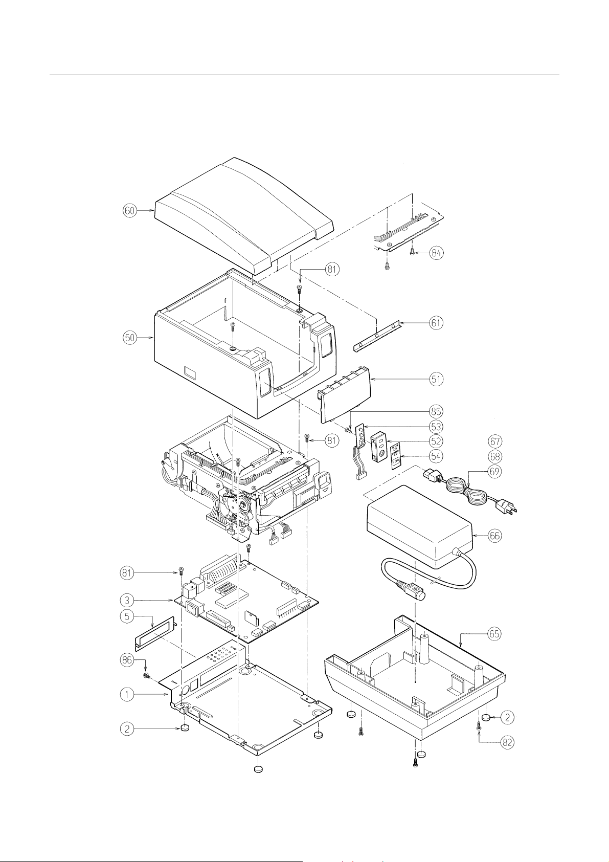
EXPLODED VIEW
CE PPPPAAAARRRRTTTTS
CE CE
s LLLLiiiisssst
t ffffoooor M
s s
r Meeeecccchhhhaaaannnniiiissssmmmm
t t
r Mr M
S LLLLIIIISSSSTTTT
S S
Ref. No. Parts No. Description Q'ty Remarks
1 E 4002-590 Bottom Chassis 1
2 E 6302-370
3 E 70010990 Control PCB Assy (P) 1
4 E 70010995 Control PCB Assy (R)
5
7 E 4002-600 Main Chassis 1
8 E 8017-110 Stepping Motor 1
9 E 8032-120 Pressure Arm-R 1
10 E 8021-130 Pressure Arm-L 1
11 23G74985 EXT Spring-01 3
12 E 8012-030 Lock Lever-R-SA 1
13 E 8013-040 Lock Lever-L-SA 1
14 E 6602-140 Ejector 1
15 E 6602-150 Brake 1
E 6601-410 Serial IF Plate 1
Rubber Foot (f10´3)
1/2
4
17 E 8019-200 Reduction Gear 1
18 E 8516-030 Idle Gear 1
19 E 8500-100 Gear Holder 1
22 E 8010-360 Cutter Plate 1
23 ACC-130 Auto Cutter ACC-130 1
24 E 8023-130 Safety Cover 1
25 E 6233-170 Safety Cover Shaft 1
26 23G74992 EXT Spring-03 1
28 E 8031-150 Platen 1
29 E 8025-120 Platen Bushing 2
30 E 8019-210 Platen Gear 1
32 E 6601-410 Center Frame 1
33 E 4019-230 DIP SW Cover 1
34 E 8037-030 Slider 1
35 E 8022-150 Guide Roller 1
36 E 40000350 Sensor PCB Assy 1
37 E 6601-390 Sensor Plate 1
38 E 5071-115 PNE Lever Assy 1
23
–
–
CITIZEN
Page 24
CBM1000 Service Manual
EXPLODED VIEW
Ref. No. Parts No. Description Q'ty Remarks
41 E 4002-610 Top Chassis 1
42 Thermal Head KF2003-GD30C 1
43 E 4900-650 Head Cable Assy 1
44 E 8023-120 Head Cover 1
45 E 6602-160 Damper 1
46 E 6612-05 Roller 1
47 E 8023-140 Wire Cover 1
48 E 6233-180 Chassis Shaft 1
50 E 66201-090 Top Cover 1
51 E 6200-700 Front Cover 1
52 E 40000340 Operation Panel 1
53 E 40000330 Operation PCB Assy 1
54 E 5200-370 Operation Sheet 1
60 E 62040590 Printer Cover 1
61 E 6220-670 Tear Bar 1
2/2
63 E 6601-400 Partition 1
65
E 62020420
Power Case 1
66 31AD AC Adapter 31AD 1
67 E 6100-765 AC Cord-100V 1
68 E 6100-755 AC Cord-120V
69 E 6100-730 AC Cord-230V
70 Caution Label, Paper 1
71 Caution Label, Hot 1
72 Caution Label, Drawer 1
80 23G75069
81 23G22579
82 23G22821
83 23G23251
84 23G22796
85 23G23179
86 23G42966
Screw, PH, M3´4
Screw, PHT (ST), M3´6
Screw, PHT (ST), M3´8
Screw, PHT (BT), M3´6
Screw, PHT (BT), M3´8
Screw, PHT (BT), M2.6´6
Screw, PHT (ST, EXT, TW), M3´6
15
87 23G22829 E-Ring, 4 4
88 23G65865 E-Ring, 2 2
6
4
4
2
4
1
24
–
–
CITIZEN
Page 25
CBM1000 Service Manual
5555....2222D
DDDiiiissssaaa
DDDDiiiissssaaaass
llll
sseeeemmmmbbbblllly
ssss
ass
sseeeemmmmbbbblllly
ssss
y DDDDrrrraaaawwwwiiiinnnngggg----1111
y y
y DDDDrrrraaaawwwwiiiinnnngggg
y y
25
–
–
CITIZEN
Page 26

DDDDiiiissssaaaass
llll
sseeeemmmmbbbblllly
ssss
y DDDDrrrraaaawwwwiiiinnnngggg----2222
y y
CBM1000 Service Manual
26
–
–
CITIZEN
Page 27

CBM1000 Service Manual
5555....3333P
5555....3333....1111CCCCoooonnnnttttrrrrooool
PPPaaaarrrrttt
ts
s LLLLiiiisssst
s s
Ref. No Parts No. Description
IC1 E 107-390 CPU HD6432350F20 1 1
IC2 E 104-530 Gate Array CBM202LA-00 1 1
IC3 E 107-400 Flash Memory M29F400B-70N1 1 1
IC4 E 107-380 SRAM TC551001CF-55L 1 1
IC5 E4101-720 DC/DC Converter SI-8401L 1 1
IC6 E210-130 Reset IC M51953BPF 1 1
IC7,8 E2020050 I/F IC SP232ACP 2
IC7,8 E2010680 HC-MOS SN74HC05NS 2
IC9 E2010690 HC-MOS SN74HC244NS 1
IC101 Kanji ROM CBM202KG-01 1 1
TA1 E 390-380 Tr. Array SMA7022MU 1 1
TA2 E 390-230 Tr. Array TA8428K 1 1
TR1,6,7 E 358-080 Transistor RN1302 3 3
TR2 E 358-090 FET 2SJ267 1 1
TR3,4,8,9,14 E 358-120 Transistor RN1310 5 5
TR5,10,11,15
16
TR12,13 E 359-180 Transistor 2SC4671 2 2
TR17 E 358-130 Transistor RN2302 1 1
t ffffoooor
t t
l PPPPCB
CB AAAAss
l l
CB CB
r CCCCoooonnnnttttrrrrooool
r r
ssyyyy1
ssss
l PPPPCB A
CB Assssssssyyyy
l l
CB ACB A
111////333
3
CBM1000RCBM1000
P
E 359-210 Transistor 2SC2712 5 5
D1 E 400-610 Diode 1SS193 1 1
ZD1 E 406-070 Z. Diode RD6.2FMB2 1 1
C1-4,31 C. Cap. GRM1545B224K630PT 5 5
C5 C. Cap. GRM42-6F474Z50PT 1 1
C6,7,10-13,20
29,117-124
C8 Ele. Cap. 35ZL1000M 1 1
C9 Ele. Cap. 16ZL470M 1 1
C14,15,18
102
C16,17 C. Cap. GRM40B222K50PT 2 2
C19,21-28 C. Cap. GRM40B102K50PT 9 9
C30 C. Cap. GRM1545B224K630PT 1
C30 C. Cap. GRM42-6F474Z50PT 1
C32-41 C. Cap. GRM40F104Z50PT 10
C32 C. Cap. GRM1545B224K630PT 1
C33,34 C. Cap. GRM40B102K50PT 2
C35 C. Cap. GRM40B471K50PT 1
C. Cap. GRM40F104Z50PT 16 16
C. Cap. GRM40B471K50PT 4 4
27
–
–
CITIZEN
Page 28

CBM1000 Service Manual
2222////3333
Ref. No Parts No. Description
CBM1000RCBM1000
C101,103-109 C. Cap. GRM40CH101J50PT 8 8
C111,112,115 C. Cap. GRM40CH470J50PT 3 3
C125-127 C. Cap. GRM40F104Z50PT 3
RA1,2 E 3500-370 Re. Array BCN31-8SI332J 2
R1,2,16,18,29
Chip Re. CR10-332J 8 8
33,34,42
R3,15,22,27
Chip Re. CR10-101J 6 6
47,52
R4 Chip Re. CR10-303J 1 1
R5-7,28,31,32
Chip Re. CR10-103J 15 15
35,36,43,48
53-57
R8,9 Chip Re. CR10-473J 2 2
R10,13 Chip Re.
CR01-18W J
22
R11,12 Chip Re. CR10-222J 2 2
R14 Chip Re. CR10-511J 1 1
R17,24,44,49 Chip Re. CR10-181J 4 4
R19 Chip Re.
CR10-0WJ
(1) (1)
R20,25,45 Chip Re. CR10-683J 3 3
R21,23,30,37
Chip Re. CR10-102J 9 9
38,40,41,58
60
R26,46,51 Chip Re. CR10-333J 3 3
R39 Chip Re. CR10-223J 1 1
R50 Chip Re. CR10-823J 1 1
R59 Chip Re. CR10-622J 1 1
R61 Chip Re. CR10-101J 1
P
L1,2,3,11,12
E 4009-480 Fe. Beads BLM41P600S 20 20
19-27, 43,44
46-49
L4-10,13-18
E 4009-490 Fe. Beads BLM21A121S 48 48
28-42,45
50-68
L69-82 E 4009-490 Fe. Beads BLM21A121S 14
DS1,2 E 5103-230 DIP SW. KSD08 2 2
DS3,4 E 5103-390 DIP SW. KSD04 2
CN1 E 48000690 Connector TCS7960-53-2010 1 1
CN2 E 48000940 Connector 53014-0210 1 1
28
–
–
CITIZEN
Page 29

CBM1000 Service Manual
3333////3333
Ref. No Parts No. Description
CBM1000RCBM1000
P
CN3 E 48000945 Connector 53313-3015 1 1
CN4 E 48000755 Connector 53014-0310 1 1
CN5 E 48000765 Connector 53015-0510 1 1
CN6 E 48000955 Connector S6B-PH-K-S 1 1
CN7 E 48000930 Connector 53015-0610 1 1
CN8 E 48000755 Connector 53014-0310 (1) (1)
CN9 E 48000950 Connector 53014-0710 1 1
CN10 E 48000705 Connector TM5RJ3-66 1 1
CN11 E 48000640 Connector 17LE-13250-27 (D3AC) (1)
(JPN,EUR)
E 48000645 or 17LE-13250-27 (D3CC) (1) (USA)
CN11 E 48000830 Connector 57RE-40360-730B (D29A) 1
S1 E 4003-630 SW. SF-W1P1A-01BB2 1 1
F1 E 4005-840 Fuse MS4 1 1
F2 E 4005-770 Fuse MO1.5 1 1
F3 E 4005-815 Fuse 251.500 1 1
X1 E 501-430 X'tal CSTCV20.00MXJ040 1 1
PCB PCB 1000-01 1
PCB PCB 1000-02 1
ROM Label PLD-21 1 1
29
–
–
CITIZEN
Page 30

CBM1000 Service Manual
5555....4444P
5555....4444....1111CCCCoooonnnnttttrrrrooool
PPPaaaarrrrttt
ts
s LLLLaaaayyyyoooouuuut
s s
l PPPPCB
CB AAAAss
l l
CB CB
t DDDDrrrraaaawwwwiiiinnnngggg
t t
ssy
y ((((SSSSeeeerrrriiiiaaaal
ssss
y y
l IIIInnnntttteeeerrrrffffaaaacccce
l l
e DDDD----ssssuuuub 25
e e
b 25))))
b 25b 25
30
–
–
CITIZEN
Page 31

CBM1000 Service Manual
5555....4444....2222CCCCoooonnnnttttrrrrooool
l PPPPCB
CB AAAAss
l l
CB CB
ssy
y ((((PPPPaaaarrrraaaall
ssss
y y
lleeeel
l IIIInnnntttteeeerrrrffffaaaacccceeee))))
llll
l l
31
–
–
CITIZEN
Page 32

CBM1000 Service Manual
5555....4444....3333O
OOOppppeeeerrrraaaattttiiiiooo
on
n PPPPCB
CB AAAAss
n n
CB CB
ssyyyy
ssss
Ref. No Description
LED1 LED SEL-2410E (GREEN)
LED2 LED SEL-2110S (RED)
R1 Resistor
R2 Resistor
S1 Tact Switch SKHHBV
Operation Cable Assy SEC-2855
PCB 1000-03
RD25M10-220W
RD25M10-470W
32
–
–
CITIZEN
Page 33
CBM1000 Service Manual
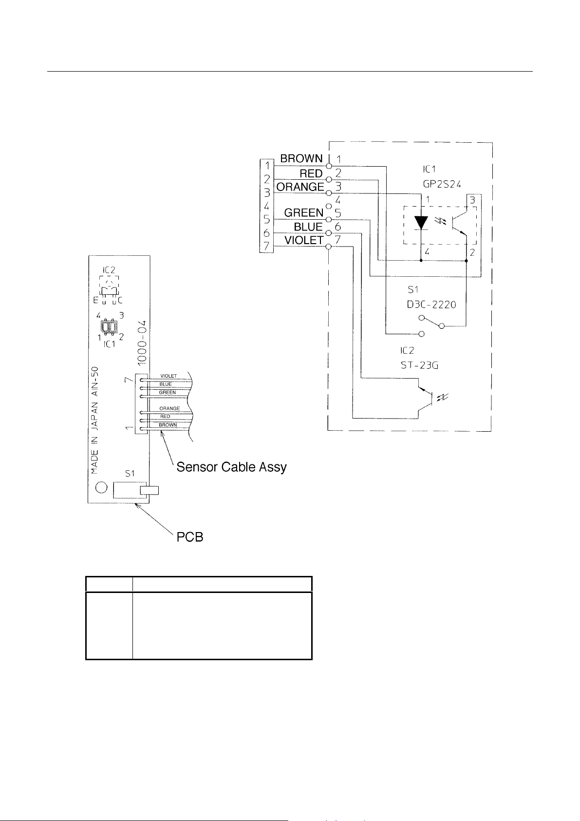
5555....4444....4444SSSSeeeennnnssssoooor
r PPPPCCCCB A
r r
B Ass
ssyyyy
B AB A
ssss
Ref. No Description
IC1 Interrupter GP2S24
IC2 Photo Transistor ST-23G-C
S1 Micro Switch D3C-2220
Sensor Cable Assy SEC-2853
PCB 1000-04
33
–
–
CITIZEN
Page 34

CBM1000 Service Manual
5555....4444....5555PPPPNNNNE
E PPPPCCCCB A
E E
B Ass
ssy
B AB A
ssss
y iiiin
n PPPPNNNNE
y y
n n
E LLLLeeeevvvveeeer
E E
r AAAAss
r r
ssyyyy
ssss
Ref. No Description
IC1 Interrupter GP2S24
PNE Cable Assy SEC-2854
PCB 1000-05
34
–
–
CITIZEN
Page 35

CBM1000 Service Manual
6666....D
DDDRRRRAAAAWWWWIIIINNNNGGG
The following list s t he reference drawings for maintenance, an d so on.
• Blo ck dia gra m
• Circuit diagrams for the following circuits
• Control PCB Assy (Seria l Interface)
• Control PCB Assy (Paral lel Interface)
G
35
–
–
CITIZEN
Page 36

CBM1000 Service Manual
6666....1111B
BBBllllooooccc
ck
k DDDDiiiiaaaaggggrrrraaaammmm
k k
36
–
–
CITIZEN
Page 37
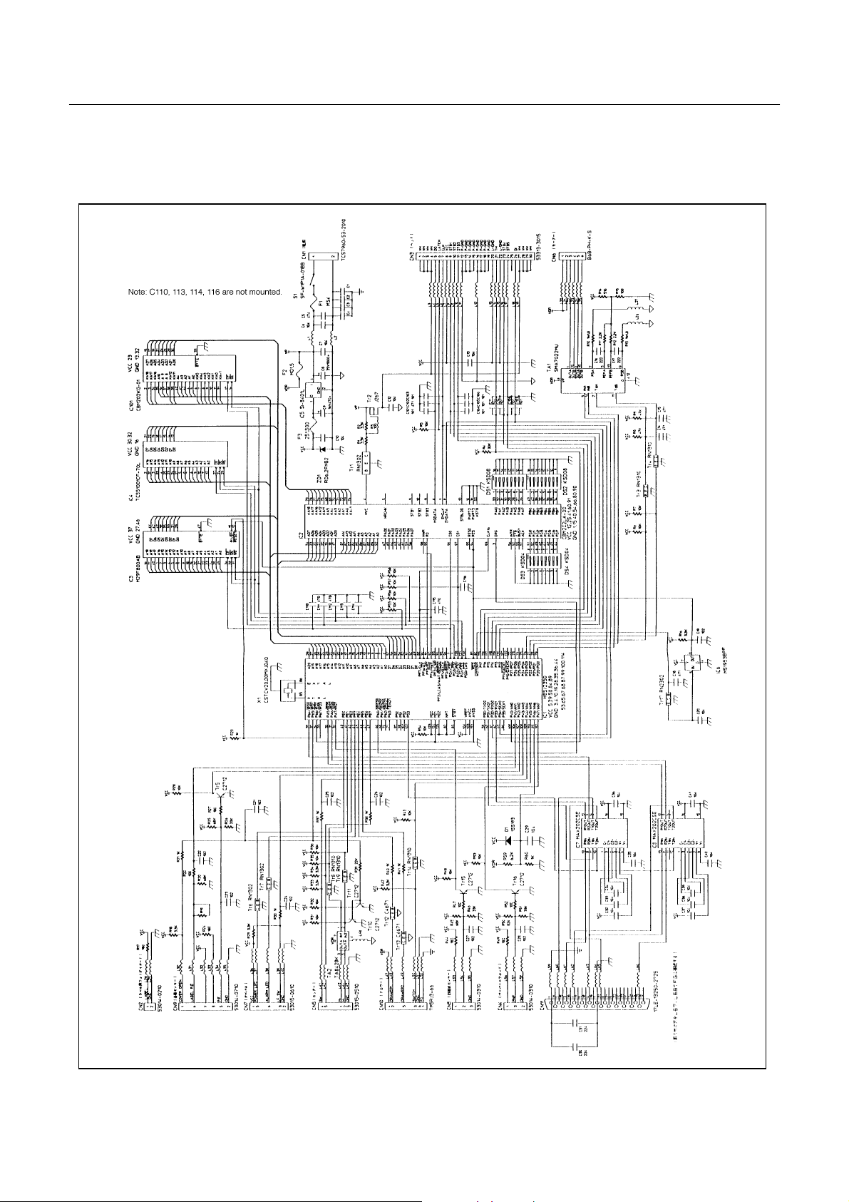
CBM1000 Service Manual
6666....2222C
CCCiiiirrrrccccuuuuiii
6666....2222....1111 CCCCoooonnnnttttrrrrooool
it
t DDDDiiiiaaaaggggrrrraaaammmm
t t
l PPPPCB
CB AAAAss
l l
CB CB
ssy
y ((((SSSSeeeerrrriiiiaaaal
ssss
y y
l IIIInnnntttteeeerrrrffffaaaacccce
l l
e DDDD----ssssuuuub 25
e e
b 25))))
b 25b 25
37
–
–
CITIZEN
Page 38
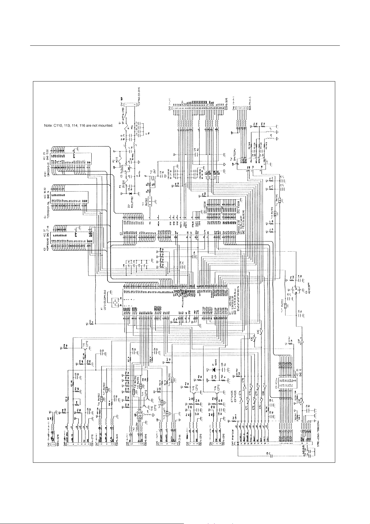
CBM1000 Service Manual
6666....2222....2222CCCCoooonnnnttttrrrrooool
l PPPPCB
CB AAAAss
l l
CB CB
ssy
y ((((PPPPaaaarrrraaaalllllllleeeel
ssss
y y
l IIIInnnntttteeeerrrrffffaaaacccceeee))))
l l
38
–
–
CITIZEN
Page 39

CBM1000 Service Manual
7777....O
CCCCMMMMBBBB1000
llll
Unit: mm
TER
ER DDDDIIIIMMMMEEEENNNNSSSSIIIIOOOONNNN
OOOUUUUTTT
ER ER
1000SSSS
10001000
39
–
–
CITIZEN
Page 40

CBM1000 Service Manual
CCCCBBBBMMMM100
llll
1000000AAAA////CCCCBBBBMMMM10
100100
1000000000DDDD
1010
Unit: mm
40
–
–
CITIZEN
Page 41

CBM1000 Service Manual
AC
AC AAAAddddaaaapppptttteeeer
llll
AC AC
r ((((33331
1 AAAADDDD))))
r r
1 1
Unit: mm
41
–
–
CITIZEN
 Loading...