


Cisco Catalyst 2960-L Manual
Cisco Catalyst 2960-L Series 8-Port and 16-Port Switch Hardware Installation Guide
First Published: 2016-09-30
Last Modified: --
Americas Headquarters
Cisco Systems, Inc. 170 West Tasman Drive
San Jose, CA 95134-1706 USA http://www.cisco.com Tel: 408 526-4000
800 553-NETS (6387) Fax: 408 527-0883
Text Part Number:
THE SPECIFICATIONS AND INFORMATION REGARDING THE PRODUCTS IN THIS MANUAL ARE SUBJECT TO CHANGE WITHOUT NOTICE. ALL STATEMENTS, INFORMATION, AND RECOMMENDATIONS IN THIS MANUAL ARE BELIEVED TO BE ACCURATE BUT ARE PRESENTED WITHOUT WARRANTY OF ANY KIND, EXPRESS OR IMPLIED. USERS MUST TAKE FULL RESPONSIBILITY FOR THEIR APPLICATION OF ANY PRODUCTS.
THE SOFTWARE LICENSE AND LIMITED WARRANTY FOR THE ACCOMPANYING PRODUCT ARE SET FORTH IN THE INFORMATION PACKET THAT SHIPPED WITH THE PRODUCT AND ARE INCORPORATED HEREIN BY THIS REFERENCE. IF YOU ARE UNABLE TO LOCATE THE SOFTWARE LICENSE OR LIMITED WARRANTY, CONTACT YOUR CISCO REPRESENTATIVE FOR A COPY.
The following information is for FCC compliance of Class A devices: This equipment has been tested and found to comply with the limits for a Class A digital device, pursuant to part 15 of the FCC rules. These limits are designed to provide reasonable protection against harmful interference when the equipment is operated in a commercial environment. This equipment generates, uses, and can radiate radio-frequency energy and, if not installed and used in accordance with the instruction manual, may cause harmful interference to radio communications. Operation of this equipment in a residential area is likely to cause harmful interference, in which case users will be required to correct the interference at their own expense.
The following information is for FCC compliance of Class B devices: This equipment has been tested and found to comply with the limits for a Class B digital device, pursuant to part 15 of the FCC rules. These limits are designed to provide reasonable protection against harmful interference in a residential installation. This equipment generates, uses and can radiate radio frequency energy and, if not installed and used in accordance with the instructions, may cause harmful interference to radio communications. However, there is no guarantee that interference will not occur in a particular installation. If the equipment causes interference to radio or television reception, which can be determined by turning the equipment off and on, users are encouraged to try to correct the interference by using one or more of the following measures:
•
•
•
•
Reorient or relocate the receiving antenna.
Increase the separation between the equipment and receiver.
Connect the equipment into an outlet on a circuit different from that to which the receiver is connected.
Consult the dealer or an experienced radio/TV technician for help.
Modifications to this product not authorized by Cisco could void the FCC approval and negate your authority to operate the product
The Cisco implementation of TCP header compression is an adaptation of a program developed by the University of California, Berkeley (UCB) as part of UCB’s public domain version of the UNIX operating system. All rights reserved. Copyright © 1981, Regents of the University of California.
NOTWITHSTANDING ANY OTHER WARRANTY HEREIN, ALL DOCUMENT FILES AND SOFTWARE OF THESE SUPPLIERS ARE PROVIDED "AS IS" WITH ALL FAULTS. CISCO AND THE ABOVE-NAMED SUPPLIERS DISCLAIM ALL WARRANTIES, EXPRESSED OR IMPLIED, INCLUDING, WITHOUT LIMITATION, THOSE OF MERCHANTABILITY, FITNESS FOR A PARTICULAR PURPOSE AND NONINFRINGEMENT OR ARISING FROM A COURSE OF DEALING, USAGE, OR TRADE PRACTICE.
IN NO EVENT SHALL CISCO OR ITS SUPPLIERS BE LIABLE FOR ANY INDIRECT, SPECIAL, CONSEQUENTIAL, OR INCIDENTAL DAMAGES, INCLUDING, WITHOUT LIMITATION, LOST PROFITS OR LOSS OR DAMAGE TO DATA ARISING OUT OF THE USE OR INABILITY TO USE THIS MANUAL, EVEN IF CISCO OR ITS SUPPLIERS HAVE BEEN ADVISED OF THE POSSIBILITY OF SUCH DAMAGES.
Any Internet Protocol (IP) addresses and phone numbers used in this document are not intended to be actual addresses and phone numbers. Any examples, command display output, network topology diagrams, and other figures included in the document are shown for illustrative purposes only. Any use of actual IP addresses or phone numbers in illustrative content is unintentional and coincidental.
Cisco and the Cisco logo are trademarks or registered trademarks of Cisco and/or its affiliates in the U.S. and other countries. To view a list of Cisco trademarks, go to this URL: http:// www.cisco.com/go/trademarks. Third-party trademarks mentioned are the property of their respective owners. The use of the word partner does not imply a partnership relationship between Cisco and any other company. (1110R)
© Cisco Systems, Inc. All rights reserved.

C O N T E N T S
P r e f a c e
C H A P T E R 1
Preface vii
Document Conventions vii
Related Documentation ix
Obtaining Documentation and Submitting a Service Request ix
Product Overview 1
Switch Models 1
Front Panel 2
PoE Ports 4
10/100/1000 Ports 5
Console Ports 5
SFP Module Slots 5
LEDs 6
System LED 7
Port LEDs and Modes 7
PoE LED 8
Console LEDs 9
Port LEDs 9
Rear Panel 10
Internal Power Supply 11
Security Slot 12
Network Configurations 12
C H A P T E R 2
Switch Installation 13
Safety Warnings 13
Box Contents 16
Tools and Equipment 17
Cisco Catalyst 2960-L Series 8-Port and 16-Port Switch Hardware Installation Guide
iii

Contents
Installation Guidelines 17
Verifying Switch Operation 18
Mounting the Switch 18
Mounting on a Desk or Shelf Without Mounting Screws 18
On a Desk, Shelf, or Wall (with Mounting Screws) 19
Deskor Shelf-Mounting 19
Under a Deskor Shelf-Mounting 20
Wall-Mounting 22
With a Mounting Tray 24
Mounting Tray with Screws 25
Mounting Tray with a Magnet 27
In a Rack 29
On a DIN Rail 31
Attaching the DIN-Mount Tray to the Switch 32
Mounting the Switch on a DIN Rail 33
Removing the Switch from a DIN Rail 35
Installing the Power Cord Retainer (Optional) 36
Installing the Cable Guard (Optional) 39
Installing SFP Modules 42
Installing an SFP Module 42
Removing an SFP Module 44
10/100/1000 PoE and PoE+Port Connections 44
10/100/1000 Port Connections 46
Auto-MDIX Connections 46
C H A P T E R 3
Troubleshooting 47
Diagnosing Problems 47
Switch POST Results 47
Switch LEDs 47
Switch Connections 47
Bad or Damaged Cable 47
Ethernet and Fiber-Optic Cables 48
Link Status 48
10/100/1000 Port Connections 48
10/100/1000 PoE+ Port Connections 49
Cisco Catalyst 2960-L Series 8-Port and 16-Port Switch Hardware Installation Guide
iv

Contents
A P P E N D I X A
A P P E N D I X B
A P P E N D I X C
SFP Module 49
Interface Settings 49
Ping End Device 50
Spanning Tree Loops 50
Switch Performance 50
Speed, Duplex, and Autonegotiation 50
Autonegotiation and Network Interface Cards 50
Cabling Distance 51
Finding the Switch Serial Number 51
Technical Specifications 53
Physical Specifications 53
Environmental Specifications 54
Power Requirements 54
PoE Power Consumption 55
Connector and Cable Specifications 57
Connector Specifications 57
10/100/1000 Ports (Including PoE) 57
SFP Module Connectors 58
Cables and Adapters 58
SFP Module Cables 58
Cable Pinouts 60
Console Port Adapter Pinouts 61
Configuring the Switch 63 |
|
|
|
Configuring the Switch Using the Configuration Setup Wizard |
63 |
||
Quick Setup: Accessing the Configuration Setup Wizard 63 |
|
||
Completing the Configuration Setup Wizard |
64 |
|
|
Configuring the Switch Using the CLI 64 |
|
|
|
Accessing the CLI Through the Console Port |
64 |
|
|
Connecting the RJ-45 Console Port |
65 |
|
|
Connecting the USB Console Port |
66 |
|
|
Installing the Cisco Microsoft Windows USB Device Driver |
67 |
||
Installing the Cisco Microsoft Windows XP USB Driver |
67 |
||
Cisco Catalyst 2960-L Series 8-Port and 16-Port Switch Hardware Installation Guide
v

Contents
Installing the Cisco Microsoft Windows 2000 USB Driver 68
Installing the Cisco Microsoft Windows Vista and Windows 7 USB Driver 68
Uninstalling the Cisco Microsoft Windows USB Driver 69
Uninstalling the Cisco Microsoft Windows XP and 2000 USB Driver 69
Using the Setup.exe Program 69
Using the Add or Remove Programs Utility 70
Uninstalling the Cisco Microsoft Windows Vista and Windows 7 USB Driver 70
Cisco Catalyst 2960-L Series 8-Port and 16-Port Switch Hardware Installation Guide
vi

Preface
• Document Conventions, page vii
• Related Documentation, page ix
• Obtaining Documentation and Submitting a Service Request, page ix
Document Conventions
This document uses the following conventions:
Convention |
Description |
^ or Ctrl |
Both the ^ symbol and Ctrl represent the Control (Ctrl) key on a keyboard. For |
|
example,thekeycombination ^D or Ctrl-D meansthatyouholddowntheControl |
|
key while you press the D key. (Keys are indicated in capital letters but are not |
|
case sensitive.) |
bold font |
Commands and keywords and user-entered text appear in bold font. |
Italic font |
Document titles, new or emphasized terms, and arguments for which you supply |
|
values are in italic font. |
Courier font |
Terminal sessions and information the system displays appear in courier font. |
Bold Courier font |
Bold Courier font indicates text that the user must enter. |
[x] |
Elements in square brackets are optional. |
... |
An ellipsis (three consecutive nonbolded periods without spaces) after a syntax |
|
element indicates that the element can be repeated. |
| |
A vertical line, called a pipe, indicates a choice within a set of keywords or |
|
arguments. |
[x | y] |
Optional alternative keywords are grouped in brackets and separated by vertical |
|
bars. |
Cisco Catalyst 2960-L Series 8-Port and 16-Port Switch Hardware Installation Guide
vii
Preface
Document Conventions
Convention |
Description |
{x | y} |
Required alternative keywords are grouped in braces and separated by vertical |
|
bars. |
[x {y | z}] |
Nested set of square brackets or braces indicate optional or required choices |
|
within optional or required elements. Braces and a vertical bar within square |
|
brackets indicate a required choice within an optional element. |
string |
A nonquoted set of characters. Do not use quotation marks around the string or |
|
the string will include the quotation marks. |
< > |
Nonprinting characters such as passwords are in angle brackets. |
[ ] |
Default responses to system prompts are in square brackets. |
!, # |
An exclamation point (!) or a pound sign (#) at the beginning of a line of code |
|
indicates a comment line. |
Reader Alert Conventions
This document may use the following conventions for reader alerts:
Note Means reader take note. Notes contain helpful suggestions or references to material not covered in the manual.
Tip Means the following information will help you solve a problem.
Caution Means reader be careful. In this situation, you might do something that could result in equipment damage or loss of data.
Timesaver Means the described action saves time. You can save time by performing the action described in the paragraph.
Warning IMPORTANT SAFETY INSTRUCTIONS
This warning symbol means danger. You are in a situation that could cause bodily injury. Before you work on any equipment, be aware of the hazards involved with electrical circuitry and be familiar with standard practices for preventing accidents. Use the statement number provided at the end of each warning to locate its translation in the translated safety warnings that accompanied this device. Statement 1071
SAVE THESE INSTRUCTIONS
Cisco Catalyst 2960-L Series 8-Port and 16-Port Switch Hardware Installation Guide
viii

Preface
Related Documentation
Related Documentation
•Cisco SFP modules documentation, including compatibility matrixes, located at: http://www.cisco.com/en/US/products/hw/modules/ps5455/tsd_products_support_series_home.html
•Cisco Validated Designs documents at this URL: http://www.cisco.com/go/designzone
Obtaining Documentation and Submitting a Service Request
Forinformationonobtainingdocumentation,submittingaservicerequest,andgatheringadditionalinformation, see the monthly What's New in Cisco Product Documentation, which also lists all new and revised Cisco technical documentation, at:
http://www.cisco.com/c/en/us/td/docs/general/whatsnew/whatsnew.html
Subscribe to the What's New in Cisco Product Documentation as a Really Simple Syndication (RSS) feed and set content to be delivered directly to your desktop using a reader application. The RSS feeds are a free service and Cisco currently supports RSS version 2.0.
Cisco Catalyst 2960-L Series 8-Port and 16-Port Switch Hardware Installation Guide
ix

Preface
Obtaining Documentation and Submitting a Service Request
Cisco Catalyst 2960-L Series 8-Port and 16-Port Switch Hardware Installation Guide
x
C H A P T E R 1
Product Overview
The Cisco Catalyst 2960-L Series switches are fixed-configuration, Gigabit Ethernet switches that provide entry-level enterprise-class Layer 2 access for branch offices, conventional workspace, and out-of-wiring closet applications.
Cisco Catalyst 2960-L Series switches provide support for the following features:
•8, 16, 24 or 48 Gigabit Ethernet ports with line-rate forwarding performance
•Two or four Gigabit Small Form-Factor Pluggable (SFP) uplinks
•Power over Ethernet Plus (PoE+) support with up to 370W of PoE budget and Persistent PoE
•Fanless operation with operational temperature up to 45°C for deployment outside the wiring closet
•Reduced power consumption and advanced energy management
•RJ-45 and USB Mini-Type B console ports
•USB Type A port supports file system
• Switch Models, page 1
• Front Panel, page 2
• Rear Panel, page 10
• Network Configurations, page 12
Switch Models
Table 1: Cisco Catalyst 2960-L 8-Port and 16-Port Switch Models and Description
Switch Model |
Software |
Description |
|
Image |
|
WS-C2960L-8TS-LL |
Lan Lite |
8 10/100/1000 Ethernet ports; 2 1-Gigabit small form-factor pluggable |
|
|
(SFP) module uplink slots. |
Cisco Catalyst 2960-L Series 8-Port and 16-Port Switch Hardware Installation Guide
1

Product Overview
Front Panel
Switch Model |
Software |
Description |
|
Image |
|
WS-C2960L-8PS-LL |
Lan Lite |
8 10/100/1000 Power over Ethernet plus (PoE+) ports (PoE budget of |
|
|
67W); 2 1-Gigabit small form-factor pluggable (SFP) module uplink |
|
|
slots. |
WS-C2960L-16TS-LL |
Lan Lite |
16 10/100/1000 Ethernet ports; 2 1-Gigabit small form-factor pluggable |
|
|
(SFP) module uplink slots. |
WS-C2960L-16PS-LL |
Lan Lite |
16 10/100/1000 Power over Ethernet plus (PoE+) ports (PoE budget of |
|
|
120W); 2 1-Gigabit small form-factor pluggable (SFP) module uplink |
|
|
slots. |
Front Panel
This section describes the front panel components of a 8-port and 16-port Cisco Catalyst 2960-L switch.
•8 or 16 downlink Ethernet ports of one of these types:
◦10/100/1000
◦10/100/1000 PoE+
•2 SFP module ports
•RJ-45 console port
•USB mini-Type B (console) port
•USB Type A port
Cisco Catalyst 2960-L Series 8-Port and 16-Port Switch Hardware Installation Guide
2
Product Overview
Front Panel
• LEDs
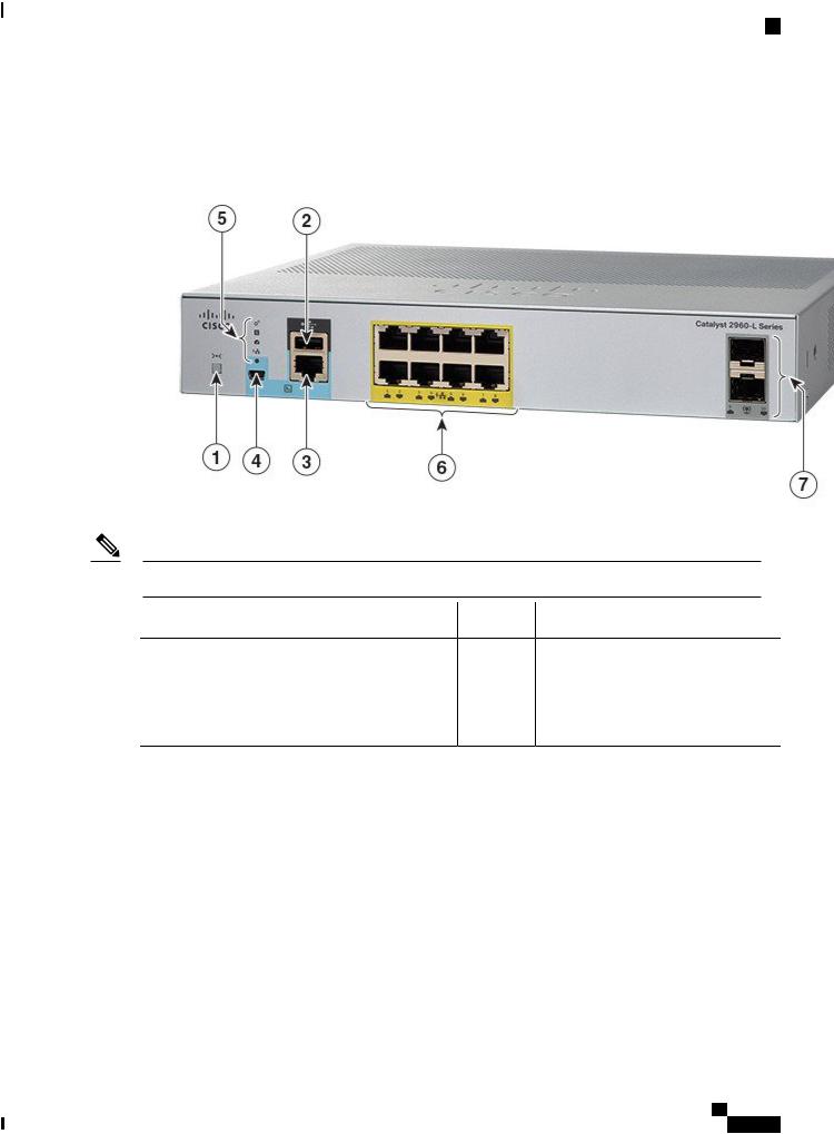
Figure 1: Front Panel of an 8-Port Cisco Catalyst 2960-L PoE Switch
Note The yellow color marking around the ports indicates that the switch is a PoE switch.
1 |
Mode button |
5 |
System LEDs |
2 |
USB Type A port |
6 |
8 10/100/1000 PoE+ ports |
3 |
RJ-45 Console Port |
7 |
SFP module slots |
4USB mini-Type B (console) port
Cisco Catalyst 2960-L Series 8-Port and 16-Port Switch Hardware Installation Guide
3
Product Overview
PoE Ports
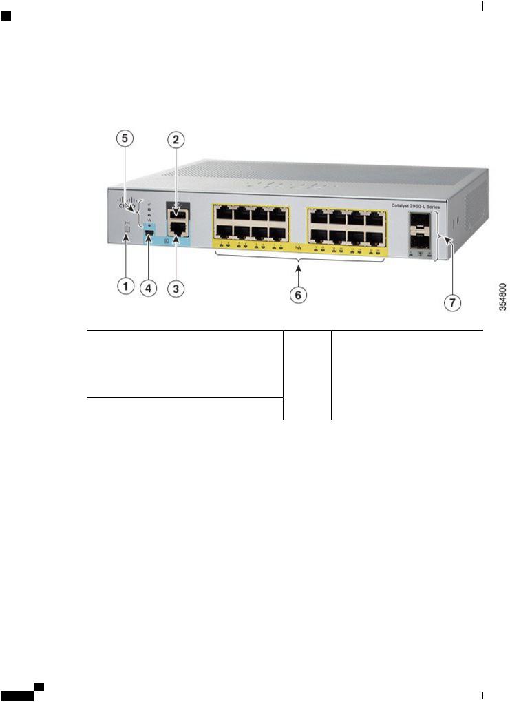
Figure 2: Front Panel of a 16-Port Cisco Catalyst 2960-L PoE Switch
1 |
Mode button |
5 |
System LEDs |
2 |
USB Type A port |
6 |
16 10/100/1000 PoE+ ports |
3 |
RJ-45 Console Port |
7 |
SFP module slots |
4USB mini-Type B (console) port
PoE Ports
The ports provide PoE support for devices compliant with IEEE 802.3af and IEEE 802.3at and also provide PoE support for Cisco IP Phones and Cisco Aironet Access Points. The PoE switch ports are Power Source equipment (PSE) and Power Device (PD) capable and source power to PD devices connected to the downlink ports. A switch can source POE power of up to 30.8W per port.
Depending on the switch model and the number of PoE ports, the maximum switch power output varies between 91.66 W to 150.11 W. On a per-port basis, you can control whether or not a port automatically provides power when an IP phone or an access point is connected.
The PoE ports use RJ-45 connectors with Ethernet pinouts. The 10BASE-T, 100BASE-TX, 1000BASE-T traffic requires Category 5 or Category 5e twisted pair (UTP) cable. The 10BASE-T traffic can use Category 3 or Category 4 UTP cable.
Cisco Catalyst 2960-L Series 8-Port and 16-Port Switch Hardware Installation Guide
4
Product Overview
10/100/1000 Ports
10/100/1000 Ports
The 10/100/1000 ports use RJ-45 connectors with Ethernet pinouts. The maximum cable length is 328 feet (100 meters). The 10BASE-T, 100BASE-TX, 1000BASE-T traffic requires Category 5 or Category 5e twisted pair (UTP) cable. The 10BASE-T traffic can use Category 3 or Category 4 UTP cable.
Console Ports
The console ports connect the switch to a PC running Microsoft Windows or to a terminal server.
•RJ-45 console port (EIA/TIA-232). The RJ-45 console port connection uses an RJ-45-to-DB-9 female cable.
•USB mini-Type B console port (5-pin connector).
If you use the USB mini-Type B console port, the Cisco Windows USB device driver must be installed on any PC connected to the console port (for operation with Microsoft Windows). Mac OS X or Linux do not require special drivers.
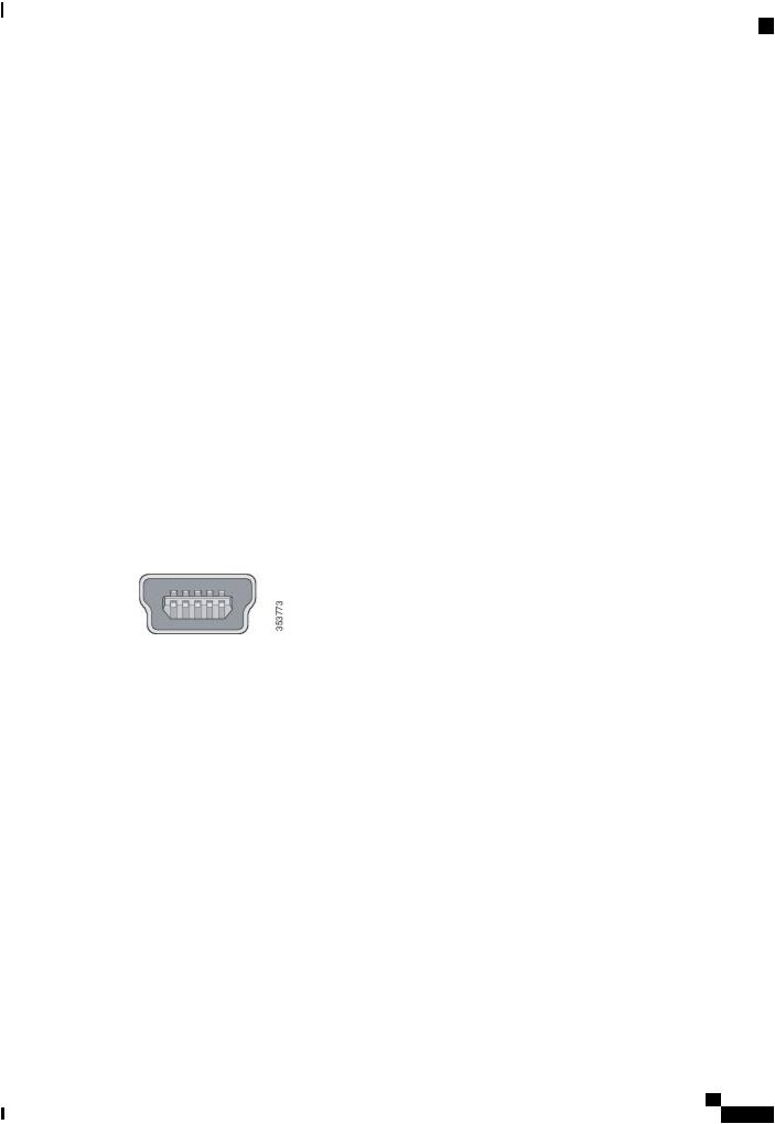
The 4-pin mini-Type B connector resembles the 5-pin mini-Type B connectors. They are not compatible. Use only the 5-pin mini-Type B.
This illustration shows a 5-pin mini-Type B USB port.
Figure 3: USB Mini-Type B Port
With the Cisco Windows USB device driver, you can connect and disconnect the USB cable from the console port without affecting Windows HyperTerminal operations.
The console output always goes to both the RJ-45 and the USB console connectors, but the console input is active on only one of the console connectors at any one time. The USB console takes precedence over the RJ-45 console. When a cable is connected into the USB console port, the RJ-45 console port becomes inactive. Conversely, when the USB cable is disconnected from the USB console port, the RJ-45 port becomes active.
You can use the command-line interface (CLI) to configure an inactivity timeout which reactivates the RJ-45 console if the USB console has been activated and no input activity has occurred on the USB console for a specified time.
After the USB console deactivates due to inactivity, you cannot use the CLI to reactivate it. Disconnect and reconnect the USB cable to reactivate the USB console. For information on using the CLI to configure the USB console interface, see the software guide.
SFP Module Slots
The switch has two 1-Gigabit SFP module slots. The SFP slots support only the SFP modules.
Cisco Catalyst 2960-L Series 8-Port and 16-Port Switch Hardware Installation Guide
5

Product Overview
LEDs
For Cisco SFP modules documentation, including compatibility matrixes, refer to this URL: http:// www.cisco.com/en/US/products/hw/modules/ps5455/products_device_support_tables_list.html
LEDs
You can use the switch system and port LEDs to monitor switch activity and performance.
Figure 4: Switch LEDs
1 |
SYST LED (system) |
4 |
PoE LED 1 |
2 |
STAT LED (status) |
5 |
Console LED |
3 |
SPEED LED |
6 |
Port LEDs |
Cisco Catalyst 2960-L Series 8-Port and 16-Port Switch Hardware Installation Guide
6

Product Overview
LEDs
1 Only on switch models that support PoE.
System LED
Color |
System Status |
Off |
System is not powered on. |
Green |
System is operating normally. |
Amber |
System is receiving power but is not operating |
|
properly. |
Blinking Green |
POST is in progress. |
Port LEDs and Modes
The port and module slots each has a port LED. As a group or individually, the LEDs display information about the switch and about the individual ports.
Table 2: Port Mode LEDs |
|
|
LED |
Port Mode |
Description |
STAT |
Port status |
The port status. This is the default mode. |
SPEED |
Port speed |
The port operating speed: 10, 100, or 1000 |
|
|
Mb/s. |
PoE |
PoE port power |
The PoE status. |
To select or change a mode, press the Mode button until the desired mode is highlighted. When you change port modes, the meanings of the port LED colors also change.
Cisco Catalyst 2960-L Series 8-Port and 16-Port Switch Hardware Installation Guide
7

Product Overview
LEDs
Table 3: Meanings of LED Colors in Different Modes |
|
||
LED |
Port Mode |
Color |
Description |
STAT |
Port status |
Off |
No link or port is administratively shut down. |
|
|
Green |
Link is present. |
|
|
Blinking green |
Activity. Port is sending or receiving data. |
|
|
Alternating green |
Link fault. Error frames can affect connectivity, and errors |
|
|
amber |
such as excessive collisions, CRC errors, and alignment |
|
|
|
errors are monitored for link faults. |
|
|
Amber |
Port is blocked by Spanning Tree Protocol (STP) and is not |
|
|
|
forwarding data. After a port is reconfigured, the port LED |
|
|
|
is amber for up to 30 seconds as STP searches for loops. |
|
|
Blinking amber |
Port is blocked by STP and is not sending data. |
SPEED |
Port speed |
Off |
Port is operating at 10 Mb/s. |
|
|
Green |
Port is operating at 100 Mb/s.2 |
|
|
Blinking green |
Port is operating at 1000 Mb/s. |
PoE |
PoE port |
Off |
PoE is off. If the powered device is receiving power from |
|
power |
|
an AC power source, the PoE port LED is off even if the |
|
|
|
powered device is connected to the switch port. |
|
|
Green |
PoE is on. The port LED is green only when the switch port |
|
|
|
is providing power. |
|
|
Alternating green |
PoE is denied because providing power to the powered |
|
|
amber |
device will exceed the switch power capacity. |
|
|
Amber |
PoE for the port is disabled. By default, PoE is enabled. |
|
|
Blinking Amber |
PoE is off due to a fault. |
2 Applies only to RJ-45 ports.
PoE LED
Even if the PoE mode is not selected, the LED shows PoE problems when they are detected. The PoE LED is only on the switches that support PoE.
Color |
Description |
Off |
PoE mode is not selected. |
Cisco Catalyst 2960-L Series 8-Port and 16-Port Switch Hardware Installation Guide
8

Product Overview
LEDs
Color |
Description |
Green |
PoE mode is selected. Ports are functioning correctly. |
Blinking amber
•PoE mode is not selected
•At least one of the 10/100 or 10/100/100 PoE ports has been denied power
•At least one of the ports has a PoE fault
Console LEDs
The console LEDs show which console port is in use.
If you connect a cable to a console port, the switch automatically uses that port for console communication. If you connect two console cables, the USB-mini console port has priority.
LED |
Color |
Description |
USB-mini console port |
Green |
USB-mini console port is active. |
|
Off |
Port is not active. |
|
|
RJ-45 console port is active. |
Port LEDs
RJ-45 ports and SFP-module slots have port LEDs. These LEDs, as a group or individually, provide information about the switch and about the individual ports.
LED Color |
Description |
|
Off |
No link or port was administratively shut down. |
|
Green |
Link present but is not sending or receiving data. |
|
Blinking green |
Activity. Port is sending or receiving data. |
|
|
Note |
Currently this is not supported for SFP |
|
|
ports. |
Alternating green-amber |
Link fault. Error frames can affect connectivity, and errors such as |
|
|
excessive collisions, CRC errors, and alignment and jabber errors are |
|
|
monitored for link faults. |
|
|
Note |
Currently this is not supported for SFP |
|
|
ports. |
Cisco Catalyst 2960-L Series 8-Port and 16-Port Switch Hardware Installation Guide
9
Product Overview
Rear Panel
LED Color |
Description |
|
Amber |
Port is blocked by Spanning Tree Protocol (STP) and is not forwarding |
|
|
data. After a port is reconfigured, the port LED is amber for up to 30 |
|
|
seconds as STP searches for loops. |
|
|
Note |
Currently this is not supported for SFP |
|
|
ports. |
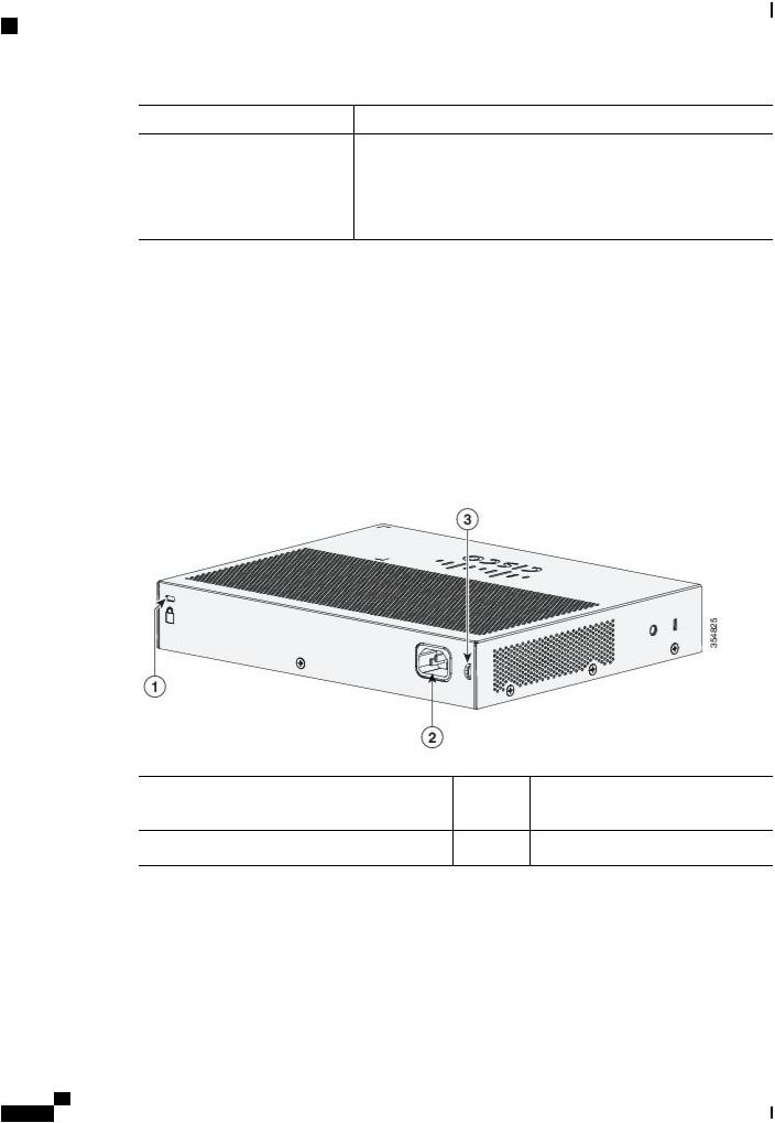
Rear Panel
•A security slot
•An AC power connector
•A loop (for the optional power cord retainer)
•Heat sink fins (PoE models only)
Figure 5: Rear Panel of a Non-PoE Switch
1 |
Security Slot |
3 |
A loop (for the optional power cord |
|
|
|
retainer) |
2An AC power connector
Cisco Catalyst 2960-L Series 8-Port and 16-Port Switch Hardware Installation Guide
10
Product Overview
Internal Power Supply
Figure 6: Rear Panel of a PoE Switch
1 |
Security Slot |
3 |
A loop (for the optional power cord |
|
|
|
retainer) |
2 |
An AC power connector |
4 |
Heat sink fins |
Internal Power Supply
All the switches are powered through their internal power supplies. The internal power supply is an autoranging unit that supports input voltages between 100 and 240 VAC (max of 90V to 264V). The AC frequency range of the power supply is 50Hz~60Hz. Plug the AC power cord into the AC power connector and into an AC power outlet.
Cisco Catalyst 2960-L Series 8-Port and 16-Port Switch Hardware Installation Guide
11
Product Overview
Security Slot
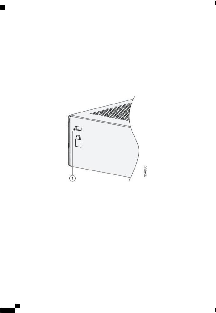
Security Slot
The switches have security slots on the rear panel. You can install an optional cable lock, such as the type that is used to secure a laptop computer, to secure the switch.
Figure 7: Switch Rear Panel
Network Configurations
See the switch software configuration guide on Cisco.com for network configuration concepts and examples of using the switch to create dedicated network segments and interconnecting the segments through Fast Ethernet and Gigabit Ethernet connections.
Cisco Catalyst 2960-L Series 8-Port and 16-Port Switch Hardware Installation Guide
12

C H A P T E R 2
Switch Installation
For initial switch setup, assigning the switch IP address, and powering on information, see the switch getting started guide on Cisco.com.
This chapter contains these topics:
• Safety Warnings, page 13
• Box Contents, page 16
• Tools and Equipment, page 17
• Installation Guidelines, page 17
• Verifying Switch Operation, page 18
• Mounting the Switch, page 18
• Installing the Power Cord Retainer (Optional), page 36
• Installing the Cable Guard (Optional), page 39
• Installing SFP Modules, page 42
• 10/100/1000 PoE and PoE+Port Connections, page 44
• 10/100/1000 Port Connections, page 46
Safety Warnings
This section includes the warning statements relating to basic installation. Read this section before you start the installation procedure.
Warning Before working on equipment that is connected to power lines, remove jewelry (including rings, necklaces, and watches). Metal objects will heat up when connected to power and ground and can cause serious burns or weld the metal object to the terminals. Statement 43
Cisco Catalyst 2960-L Series 8-Port and 16-Port Switch Hardware Installation Guide
13

Switch Installation
Safety Warnings
Warning Do not stack the chassis on any other equipment. If the chassis falls, it can cause severe bodily injury and equipment damage. Statement 48
Warning Read the wall-mounting instructions carefully before beginning installation. Failure to use the correct hardware or to follow the correct procedures could result in a hazardous situation to people and damage to the system. Statement 378
Warning Do not work on the system or connect or disconnect cables during periods of lightning activity. Statement
1001
Warning Read the installation instructions before connecting the system to the power source. Statement 1004
Warning To prevent bodily injury when mounting or servicing this unit in a rack, you must take special precautions to ensure that the system remains stable. The following guidelines are provided to ensure your safety:
•This unit should be mounted at the bottom of the rack if it is the only unit in the rack.
•When mounting this unit in a partially filled rack, load the rack from the bottom to the top with the heaviest component at the bottom of the rack.
•If the rack is provided with stabilizing devices, install the stabilizers before mounting or servicing the unit in the rack.
Warning
Warning
Warning
Warning
Statement 1006
Class 1 laser product. Statement 1008
This unit is intended for installation in restricted access areas. A restricted access area can be accessed only through the use of a special tool, lock and key, or other means of security. Statement 1017
The plug-socket combination must be accessible at all times, because it serves as the main disconnecting device. Statement 1019
This equipment must be grounded. Never defeat the ground conductor or operate the equipment in the absence of a suitably installed ground conductor. Contact the appropriate electrical inspection authority or an electrician if you are uncertain that suitable grounding is available. Statement 1024
Cisco Catalyst 2960-L Series 8-Port and 16-Port Switch Hardware Installation Guide
14

Switch Installation
Safety Warnings
Warning Only trained and qualified personnel should be allowed to install, replace, or service this equipment.
Statement 1030
Warning Ultimate disposal of this product should be handled according to all national laws and regulations.
Statement 1040
Warning When installing or replacing the unit, the ground connection must always be made first and disconnected last. Statement 1046
Warning To prevent the system from overheating, do not operate it in an area that exceeds the maximum recommended ambient temperature of: <113°F (45°C). Statement 1047
Note The maximum operating temperature is 40°C for Catalyst WS-C2960L-16PS-LL switches and 45°C for all the other switch models.
Warning Invisible laser radiation may be emitted from disconnected fibers or connectors. Do not stare into beams or view directly with optical instruments. Statement 1051
Warning This warning symbol means danger. You are in a situation that could cause bodily injury. Before you work on any equipment, be aware of the hazards involved with electrical circuitry and be familiar with standard practices for preventing accidents. Use the statement number provided at the end of each warning to locate its translation in the translated safety warnings that accompanied this device. Statement 1071
Warning Voltages that present a shock hazard may exist on Power over Ethernet (PoE) circuits if interconnections are made using uninsulated exposed metal contacts, conductors, or terminals. Avoid using such interconnection methods, unless the exposed metal parts are located within a restricted access location and users and service people who are authorized within the restricted access location are made aware of the hazard. A restricted access area can be accessed only through the use of a special tool, lock and key or other means of security. Statement 1072
Warning No user-serviceable parts inside. Do not open. Statement 1073
Warning Installation of the equipment must comply with local and national electrical codes. Statement 1074
Cisco Catalyst 2960-L Series 8-Port and 16-Port Switch Hardware Installation Guide
15
 Loading...