


CARVIN ENGINEERING DATA
DCM150 POWER AMP |
OPERATING MANUAL |
The DCM150 professional amp is designed utilizing Carvin’s years of experience in power amp technology. It meets and exceeds every standard for professional amplification. The thick brushed anodized aluminum face plate, large recessed knobs and heavy-duty aluminum chassis reflect the manufacturing quality within. The DCM150 “High Energy Transfer” amp carrys the CE approval for world-wide use.
PURE—TRANSPARENT SOUND
Carvin considers the sound of an amp equally important as its reliability. To insure pure, uncolored sound, we designed one of the fastest responding power amps on the market today. High slew rates deliver superb transient response. High frequencies are transparent and open—even at high levels. Linear feedback circuits reduce distortion to near the theoretical zero limit preventing any type of harshness which would lead to ear fatigue. The DCM150 amp delivers flat, transparent, unaltered sound—especially important to the studio user. These amps are designed to deliver non-stop, continuous power and are completely protected from heat and short circuits.
ULTRA RUGGED FOR TOURING
Every chassis is made from heavy-duty 16 gauge aluminum that is lightweight and prevents rust. All internal cabling is neatly tied and harnessed. Heavy-duty power switches, recessed knobs & machined aluminum front panels all give the DCM amps a “tank-like” ability to handle rough, touring transport.
TOTALLY MODULAR
With the DCM150, Carvin brings you totally modular construction. If you ever need an I/O (input/output) connector card because a connector wore-out, just unplug it and re-install the replacement card in minutes. You don’t have to de-solder anything. This applies to every aspect of the DCM150 amp including the power supply, power cards, and heat sinks. Everything is connected by heavy-duty connectors for easy replace- ment—even the Toroid transformer is a total plug-in.
LOSE THE WEIGHT...NOT THE PERFORMANCE
For some companies, weight reduction means cost reduction. Carvin however, uses expensive TOROID transformers to reduce weight. Toroids deliver extra amounts of “on demand” current for continuous operation. This gives the power supply a solid foundation, yielding more headroom. Not only do toroids deliver high current, but they are known for reducing stray magnetic fields eliminating hum & noise. This is especially important for the recording industry.
For your records, you may wish to record the following information.
Serial No._____________________ Invoice Date_______________
FRONT PANELS & CONNECTING UP
The DCM Series feature front panel signal, clip and protect LEDs which let you monitor the status of the amp. Both channels use precision level controls allowing you to see your settings at a glance. Balanced 1/4 phone & XLR input jacks are used to eliminate hum & noise. Speaker outputs feature 1/4” jacks. Heavy-duty binding posts that accept up to 50 amp #7 speaker wires.
The rear professional accessory group offers a GROUND switch to remove the chassis ground from the XLR input, a PARALLEL input switch connects the inputs of both channels together eliminating Y connectors and allowing amp patching in multiple amp systems. The accessory group also features a BRIDGE mode switch for delivering full power into a mono 8Ω loud.
RECEIVING INSPECTION—read before getting started
INSPECT YOUR UNIT FOR ANY DAMAGE which may have occurred during shipping. If any damage is found, please notify the shipping company and CARVIN immediately. SAVE THE CARTON & ALL PACKING MATERIALS. In the event you have to re-ship your unit, always use the original carton and packing material. This will provide the best possible protection during shipment. CARVIN and the shipping company are not liable for any damage caused by improper packing.
SAVE YOUR INVOICE. It will be required for warranty service if needed in the future. SHIPMENT SHORTAGE. If you find items missing, they may have been shipped sepa-
rately. Please allow several days for the rest of your order to arrive before inquiring. RECORD THE SERIAL NUMBER on the enclosed warranty card or below on this manual for your records. Keep your portion of the card and return the portion with your name and comments to us.
DCM150 POWER AMP SPECIFICATIONS:
Output Power |
|
(BRIDGE MONO) |
|
8Ω , 1kHz, < 1% THD |
150 Watts |
Minimum Impedance (Bridged) |
8 ohms |
(Stereo, both channels driven) |
|
8Ω , 1kHz, < 0.5% THD |
60/60 Watts |
4Ω , 1kHz, < 0.5% THD |
75/75 Watts |
Minimum Impedance |
4 ohms per channel |
THD |
|
20-20kHz |
< 0.1% |
(8Ω typical) |
< 0.05% |
Frequency Response |
±0.5 dB, 20 Hz to 20 kHz |
Input Impedance |
> 20kΩ Balanced or Unbalanced |
Damping Factor |
>400 |
Sensitivity (@ 4Ω ) |
1.0 Vrms |
Output Noise |
-102 dBm |
Power Consumption |
120V—200 VA |
Dimensions |
1 3/4” High x 19” Wide x 10” Deep |
Weight (Net) |
9lbs. |
|
12340 World Trade Drive, San Diego, CA 92128 |
76-00150 0801 |
800 854-2235 www.carvin.com |
|
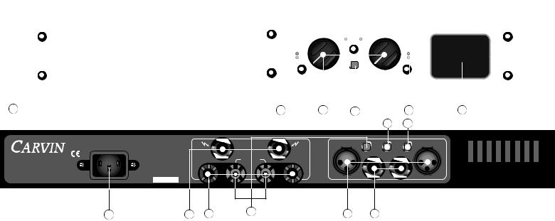
FRONT & REAR PANEL CONTROLS
|
|
|
|
|
|
|
|
|
|
|
|
|
|
|
|
|
|
|
|
|
|
12 11 |
10 |
9 |
PROTECT POWER |
10 |
9 |
|
|
|
|
|
|
|
|||
|
|
|
|
|
|
|
|
|
|
|
|
|
|
|
|
|
|
|
|
|
|
|
|
8 |
|
|
|
8 |
|
|
|
|
|
|
|||
|
|
|
|
|
|
|
|
|
|
|
|
|
|
|
|
|
|
|
13 |
|
|
|
|
7 |
|
|
|
|
7 |
|
|
|
|
|
|
||
|
|
|
|
|
|
|
|
|
|
|
|
|
|
|
|
|
|
|
15 |
|
|
|
|
6 |
|
|
|
|
6 |
|
|
|
|
|
|
||
|
|
|
|
|
|
|
|
|
|
|
|
|
|
|
|
|
|
|
17 |
|
|
|
|
5 |
|
|
17 |
|
5 |
|
|
|
|
|
|
||
|
|
|
|
|
|
|
|
|
|
|
|
|
|
|
|
|
|
|
|
|
|
|
|
|
|
4 |
|
19 |
|
4 |
|
CLIP |
|
|
|
|
|
|
|
|
|
|
|
|
|
|
|
|
|
|
|
|
|
|
|
DCM150 |
|
|
|
∞ |
|
|
|
3 |
|
|
22 |
|
3 |
|
SIGNAL |
|
|
|
|
|
|
|
|
|
|
|
|
|
|
|
|
|
|
|
|
|
|
30 |
|
|
|
0 dB |
|
|
|
|
0 dB |
|
|
|
|
|
|
||||
|
|
|
|
|
|
|
|
|
|
|
|
|
|
|
|
|
|
|
|
|
|
|
2 |
|
|
|
|
2 |
|
|
|
|
|
|
|||
|
|
|
|
|
|
|
|
|
|
|
|
|
|
|
|
|
|
PROFESSIONAL 150W AMPLIFIER |
|
|
50 |
|
|
|
|
1 |
EQ EXPAND |
|
|
1 |
|
|
|
|
|
|
|
|
|
|
|
|
|
|
|
|
|
|
|
|
|
|
|
|
|
|
|
CHANNEL ONE |
CHANNEL TWO |
|
|
|
|
|
|
||||||||||
|
|
|
|
|
|
|
|
|
|
|
|
|
|
|
|
|
|
|
|
|
|
|
|
|
|
|
|
|
|||||||||
|
|
|
|
|
|
|
|
|
|
|
|
|
|
|
|
|
|
|
|
|
|
|
|
|
|
|
|
|
|
|
|
|
|
|
|
|
|
|
|
|
|
|
|
|
|
|
|
|
|
|
|
|
|
|
|
|
|
|
|
|
|
|
|
|
|
|
|
|
|
|
|
|
|
|
|
5
13 12
DCM150
|
STEREO AMPLIFIER |
||
800-854-2235 |
8 OHMS/CH |
50 WATTS |
|
www.carvin.com |
4 OHMS/CH |
75 WATTS |
|
|
|||
MADE IN THE |
8Ω BRIDGED |
150 WATTS |
|
|
|
||
120VAC~60Hz |
SERIAL NUMBER |
||
USA 125VA INTERNAL FUSE |
|||
|
|
||
1 |
SPEAKERS |
2 |
INPUT 1 |
INPUT 2 |
|
|
|
||
|
BRIDGE |
|
GND |
PAR |
4Ω MIN |
8 OHMS |
Ω MIN. |
LIFT |
|
|
|
|||
|
MIN. |
|
|
|
14 |
10 |
11 |
|
FRONT PANEL
1. MOUNTING
The rack mounting holes are designed on ISO standard spacing. Four 10-32 x .5” phillip machine screws are normally used to secure the amp. Rear support brackets are not required.
2. POWER SWITCH
Check the power amp connections and verify the AC line power source before engaging the POWER switch. The yellow LED unmistakably indicates that all circuits are properly powered up. This color was chosen so the operator could see the red protect indicator from a distance.
3. CHANNEL LEVEL CONTROL
A precision input LEVEL attenuator is used to adjust the volume levels. To deliver the amps full power without reducing headroom of the signal source, the level controls should be turned up full.
4. CHANNEL SIGNAL INDICATOR
The green SIGNAL LED indicators will start to flash when there is a signal passing to your speakers (-30dBM). This lets you know when the amp is passing a signal to your speakers.
5. CHANNEL CLIP INDICATOR
The red CLIP LED indicators will start to flash when each channel has reached its maximum output. Occasional flashing caused by lower bass frequencies is OK. However, consistent flashing caused from higher frequencies may damage high frequency drivers (excessive distortion). This does not cause damage to the amp.
6. EQ EXPAND SWITCH
When set to the ‘in’ position this circuit will cut the mids by -4dB at 1KHz. This works well as a loudness contour when operating at low volume levels or adds tone when using it in a bass or guitar rack. When set to the ‘out’ position it provides a flat, normal response. Try it both ways and set as desired.
REAR PANEL
7. XLR CHANNEL INPUTS
For most professional applications, use the XLR balanced input. This will help to reduce hum and allow of longer cable runs from your signal source (mixer, etc). Because this is a balanced input, the gain will be 6 dB higher than using a non balanced 1/4” input. XLR pin configuration: Pin 1: Grounded through the GROUND LIFT switch, Pin 2: positive Bal. signal and Pin 3: negative Bal. signal.
8. CHANNEL 1/4” PHONE JACK INPUT
These 1/4” TRS phone jacks are designed to receive either balanced or unbalanced input signals. Balanced signals coming into this jacks should be wired with the connector’s tip going to signal + and the connector’s ring
to signal –. The connector’s sleeve is then tied to ground through the GROUND LIFT switch–.
9. SPEAKER OUTPUTS
The standard 1/4” SPEAKER jacks are used for most applications. Turn the amp off before connecting your speakers.
10. SPEAKER BINDING POSTS
For heavy-duty speaker connections, use the rear BINDING POSTS to connect your speakers. Wire sizes up to 7 gauge (50 amps) can be inserted into the binding posts “side holes”. Larger cable can be used with “banana” plugs which plug into the ends of the binding post (remove colored caps). Binding posts are spaced on ISO standards. Use the two center RED binding posts for BRIDGE speaker connections (see 11 BRIDGE MODE).
11. BRIDGE MODE—70V DISTRIBUTION SYSTEMS
The DCM150 can be operated in bridge mode if you require a 70V distribution speaker system or a high powered mono (single channel) amp. With your amp off, push in the rear BRIDGE switch after you have made your speaker connections to the rear center RED binding posts (ch 1 is + and ch 2 is -). No other speaker jack or binding post can to be used at the same time!”. The INPUT and LEVEL is handled by channel 1. Channel 2 is non-operational. The minimum speaker impedance is 8 ohms. CAUTION: The power developed by bridging your amp can destroy speakers!
12. PARALLEL OR “Y” INPUTS
The rear PARALLEL switch allows you to drive both channels from either input. All signals entering any input will be available on both channels. This eliminates Y adapter cables. This feature is used to “daisy chain” one piece of equipment to another. Just plug into the unused INPUT (1/4” or XLR) and it will become an output for other equipment.
13. INPUT GROUND LIFT
Many times sound systems are connected in such a manner to cause a grounded loop with the inputs that result in audible hum. The input GND LIFT (1/4” & XLR) switch on the rear panel will help eliminate this problem. If not, another way to eliminate ground loops is to install a “line matching” transformer between the amplifier input and the signal source and cut the ground wire to PIN 1.
14. AC POWER
Your amp is designed to run on either 120V 60 Hz. The voltage range for 120V is 95V to 132V. The rear heavy-duty AC cord is designed for your country. Be sure to check your power source before plugging into a grounded (3 prong) outlet. Never defeat the grounded connection or electrocution may result!
 Loading...