


CX1252
HELPLINE
125 250 50063 1K 2K 4K 8K 16K
L/R MAIN
2
1
0 10
9
8
7
654
3
PHANTOM
2
1
0 10
9
8
7
654
3
MONITOR
2
1
0 10
9
8
7
654
3
DSP EFF RTN
2
1
0 10
9
8
7
654
3
EFF SEND
2
1
0 10
9
8
7
654
3
TAPE / EFF RTN
L
TAPE
RTN
TAPE
SEND
L R
L R
SEND L L R
MONITOREFFECTS LINE OUT
R
127 EFFECTS
RRETURN
8 9 10
MON
PAN
11
LEVEL
MON
PAN
L R
0
12
MIC
0
8
4
4
8
–12
+12
0
8
4
4
8
–12
+12
125 250 50063 1K 2K 4K 8K 16K
8 9 10 11 12
POWER
C
X
1
2
5
2
5
4
3
2
1
0 10
9
8
7
6
5
4
3
2
1
0 10
9
8
7
6
LEVEL
L R
0
MIC
5
4
3
2
1
0 10
9
8
7
6
5
4
3
2
1
0 10
9
8
7
6
MON
PAN
LEVEL
0
MIC
5
4
3
2
1
0 10
9
8
7
6
5
4
3
2
1
0 10
9
8
7
6
MON
PAN
LEVEL
0
MIC
5
4
3
2
1
0 10
9
8
7
6
5
4
3
2
1
0 10
9
8
7
6
MON
PAN
LEVEL
0
MIC
5
4
3
2
1
0 10
9
8
7
6
5
4
3
2
1
0 10
9
8
7
6
MON
PAN
LEVEL
0
MIC
5
4
3
2
1
0 10
9
8
7
6
5
4
3
2
1
0 10
9
8
7
6
MON
PAN
LEVEL
0
MIC
5
4
3
2
1
0 10
9
8
7
6
5
4
3
2
1
0 10
9
8
7
6
MON
PAN
LEVEL
0
MIC
5
4
3
2
1
0 10
9
8
7
6
5
4
3
2
1
0 10
9
8
7
6
MON
PAN
LEVEL
0
MIC
5
4
3
2
1
0 10
9
8
7
6
5
4
3
2
1
0 10
9
8
7
6
MON
PAN
LEVEL
0
MIC
5
4
3
2
1
0 10
9
8
7
6
5
4
3
2
1
0 10
9
8
7
6
MON
PAN
LEVEL
0
MIC
5
4
3
2
1
0 10
9
8
7
6
5
4
3
2
1
0 10
9
8
7
6
MON
PAN
LEVEL
0
MIC
5
4
3
2
1
0 10
9
8
7
6
5
4
3
2
1
0 10
9
8
7
6
MIDHIMID
LOW
HI
0
3
6
9
12
3
6
9
12
0
3
6
9
12
3
6
9
12
0
3
6
9
12
3
6
9
12
0
3
6
9
12
3
6
9
12
0
3
6
9
12
3
6
9
12
0
3
6
9
12
3
6
9
12
MID
LOW
HI
0
3
6
9
12
3
6
9
12
0
3
6
9
12
3
6
9
12
0
3
6
9
12
3
6
9
12
MID
LOW
HI
0
3
6
9
12
3
6
9
12
0
3
6
9
12
3
6
9
12
0
3
6
9
12
3
6
9
12
MID
LOW
HI
0
3
6
9
12
3
6
9
12
0
3
6
9
12
3
6
9
12
0
3
6
9
12
3
6
9
12
HI
0
3
6
9
12
3
6
9
12
0
3
6
9
12
3
6
9
12
0
3
6
9
12
3
6
9
12
MID
LOW
HI
0
3
6
9
12
3
6
9
12
0
3
6
9
12
3
6
9
12
0
3
6
9
12
3
6
9
12
MID
LOW
HI
0
3
6
9
12
3
6
9
12
0
3
6
9
12
3
6
9
12
0
3
6
9
12
3
6
9
12
MID
LOW
HI
0
3
6
9
12
3
6
9
12
0
3
6
9
12
3
6
9
12
0
3
6
9
12
3
6
9
12
HI
0
3
6
9
12
3
6
9
12
0
3
6
9
12
3
6
9
12
0
3
6
9
12
3
6
9
12
MID
LOW
HI
0
3
6
9
12
3
6
9
12
0
3
6
9
12
3
6
9
12
0
3
6
9
12
3
6
9
12
MID
LOW
HI
0
3
6
9
12
3
6
9
12
0
3
6
9
12
3
6
9
12
0
3
6
9
12
3
6
9
12
L RL RL RL RL RL RL RL RL RL R
7654321
7654321
EFF /
REV54
3
2
1
0 10
9
8
7
6
EFF /
REV54
3
2
1
0 10
9
8
7
6
5
4
3
2
1
0 10
9
8
7
6
EFF /
REV54
3
2
1
0 10
9
8
7
6
EFF /
REV54
3
2
1
0 10
9
8
7
6
EFF /
REV54
3
2
1
0 10
9
8
7
6
EFF /
REV54
3
2
1
0 10
9
8
7
6
EFF /
REV54
3
2
1
0 10
9
8
7
6
5
4
3
2
1
0 10
9
8
7
6
EFF /
REV54
3
2
1
0 10
9
8
7
6
EFF /
REV54
3
2
1
0 10
9
8
7
6
EFF /
REV54
3
2
1
0 10
9
8
7
6
EFF /
REV
EFF /
REV
MID MID
AMP
PROTECT
LINELINELINELINELINELINE LINELINELINELINELINELINE
AMP
PATCH
R GRAPHIC EQ
L GRAPHIC EQ
STEREO DSP
BYPASS 1
DELAYS 2-30
REVERB 31-90
CHORUS 91-110
FLANGE 111-128
1-800-854-2235
USA
CX STEREO MIXERS
CX842 and CX1252
Record the serial number of your CX Mixer in the space provided below:
Serial No._________________ Invoice Date________________
12340 World Trade Drive
San Diego, CA 92128
OPERATION MANUAL
Manual No. 76-01252
Revision 1.1
Made in USA
1-800-854-2235
CX MIXER SPECIFICATIONS
RECEIVING INSPECTION
Frequency Response: Mic or Line Inputs: 20Hz-20KHz ±2dB
Total Harmonic Distortion: Less than .025%
Equivalent Input Noise: 150 ohm source: -120dBV
Output Noise: -80dBu non-powered mixers
(All Levels Minimum) -60dBu powered mixers
Output Power: CX1252: 250Watts RMS/side @ 4Ω
(Power Mixers Only) CX842: 200Watts RMS/side @ 4Ω
Maximum Gain: Mic in two-track main out: 70dB
Crosstalk: Adjacent ch’s: -60db at 1KHz
Common Mode Rejection: -60db at 1KHz
Phantom Power: All channels
Channel EQ.: 3 band active, LOW: 100Hz ±12dB
MID: 1.5KHz ±12dB
HI: 10KHz ±12dB
Graphic EQ.: 9 Band Oct. Intervals ±12dB
Mic Input: Balanced XLR input: -60 dBu
Line Input: Unbalanced 1/4” Phone Jack -10dBV
Power Consumption: CX1252: 620VA, CX842: 540VA
Size: Box Model: (25lbs) 11”H x 19.5”W x9”D
Rack Model: 8.75”H x 19”W x 7.75”D
FUSE SELECTION
There are two versions of the CX842 and the CX1252. A 120 Volt AC version using
the North American three prong plug and a 240 Volt AC version using the European
CEE-7 plug. The following chart shows what fuse values to use for each model.
Fuse Selector Chart for 120 VAC Models
Model Fuse Value Carvin # Size
CX1252 6A, 250V, Slow Blow 70-22060 3AG, 1/4 x 1 1/2” (6.35 x 32mm)
CX1252R 0.25A, 250V, Slow Blow 70-21002 3AG, 1/4 x 1 1/2” (6.35 x 32mm)
CX842 6A, 250V, Slow Blow 70-22060 3AG, 1/4 x 1 1/2” (6.35 x 32mm)
INSPECT YOUR CX MIXER FOR ANY DAMAGE which may have occurred
during shipping. If any damage is found, notify the shipping company and call
CARVIN immediately.
SAVE THE CARTON & ALL PACKING MATERIALS. If you have to reship
your mixer, always use the original carton and packing material. This will provide
the best possible protection for the mixer during shipment. CARVIN and the
shipping company are not liable for any damage caused by improper packing.
SAVE YOUR INVOICE. It will be required for warranty servicing of your unit.
Always check the invoice against the items you have received.
SHIPMENT SHORTAGE. If you find some items missing, it may be that they
were shipped separately. Please allow several days for the rest of your order to
arrive before inquiring. If you determine (after allowing an appropriate amount of
time) you have not received all the items you ordered, please call CARVIN.
FOR THE NEW OWNER
Congratulations on your selection of CARVlN products: “The Professional’s
Choice.” Your new CX series mixer demonstrates CARVIN’s commitment to
producing the highest quality and most sophisticated engineering in the audio
industry today. Its wide acceptance and use by industry professionals illustrates
the basis for CARVIN’s recognition as “The Professional’s Choice.”
The CX series mixers were designed to be a professional quality mixer in a compacked package. The desire was to pack as many professional features into the
smallest package we could, without sacrificing the quality of any one of the features or the mixer. The CX1252 includes a full function 12 channel stereo mixer,
two nine band graphic equalizers, a 128 preset digital signal effects processor,
and a 500 Watt stereo power amplifier capable of 250 Watts a side into 4 ohms.
The CX842 is an 8 channel stereo mixer with a 400 Watt power amplifier. The
CX842 has all the features of the CX1252 including the two nine band graphic
equalizers and the effects processor. Each CX series mixer is the size of a 5
space rackmount unit surrounded by a 3/4” poplar plywood cabinet covered with
Duratuff carpeting making the CX mixer road worthy and ready for a show anywhere.
Fuse Selector Chart for 240 VAC EXPORT Models
Model Fuse Value Carvin # Size
CX1252 3A, 250V, Slow Blow 70-22030 3AG, 1/4 x 1 1/2” (6.35 x 32mm)
CX1252R 0.125A, 250V, Slow Blow 70-21001 3AG, 1/4 x 1 1/2” (6.35 x 32mm)
CX842 3A, 250V, Slow Blow 70-22030 3AG, 1/4 x 1 1/2” (6.35 x 32mm)
19
If you would like to comment on any features or the performance of your new
mixer, please feel free to contact us. Comments from our customers have
helped us to improve and further develop our products and our business.
May you enjoy many years of success and fun with your new CARVIN mixer!
Carvin’s toll free number: 800-854-2235
i
CX STEREO SERIES PARTS LIST
QUICK START UP
CAUTION
RISK OF ELECTRIC SHOCK
Ref Des Description CARVIN No.
A1 IC4558 Op Amp Dual 60-45580
A2 IC4558 Op Amp Dual 60-45580
A3 IC4558 Op Amp Dual 60-45580
A4 IC4558 Op Amp Dual 60-45580
A5 IC4558 Op Amp Dual 60-45580
A6 IC4558 Op Amp Dual 60-45580
A7 IC4558 Op Amp Dual 60-45580
A9 IC4558 Op Amp Dual 60-45580
A10 IC4558 Op Amp Dual 60-45580
A11 IC4558 Op Amp Dual 60-45580
A12 IC4558 Op Amp Dual 60-45580
A13 IC4558 Op Amp Dual 60-45580
A14 IC4558 Op Amp Dual 60-45580
A15 IC4558 Op Amp Dual 60-45580
A16 IC4558 Op Amp Dual 60-45580
A17 IC4558 Op Amp Dual 60-45580
A18 IC4558 Op Amp Dual 60-45580
A19 IC4558 Op Amp Dual 60-45580
C1 Capacitor Ceramic 82PF 500 Volt 5% 45-82052
C2 Capacitor Ceramic 82PF 500 Volt 5% 45-82052
C3 Capacitor Electrolytic 10µF 50 Volt 20% 47-10051
C4 Capacitor Electrolytic 10µF 50 Volt 20% 47-10051
C5 Capacitor Electrolytic 10µF 50 Volt 20% 47-10051
C6 Capacitor Electrolytic 10µF 50 Volt 20% 47-10051
C7 Capacitor Ceramic 27PF 500 Volt 5% 45-27052
C8 Capacitor Ceramic 27PF 500 Volt 5% 45-27052
C9 Capacitor Ceramic 330PF 1000 Volt 10% 45-33113
C10 Capacitor Poly .0047µF 100 Volt 10% 46-47212
C11 Capacitor Ceramic 39PF 500 Volt 5% 45-39052
C12 Capacitor Electrolytic 47µF 63Volt 20% 47-47061
C13 Capacitor Electrolytic 10µF 50 Volt 20% 47-10051
C14 Capacitor Poly .047µF 100 Volt 10% 46-47312
C15 Capacitor Poly .047µF 100 Volt 10% 46-47312
C16 Capacitor Electrolytic 10µF 50 Volt 20% 47-10051
C17 N/U
C18 Capacitor Electrolytic 470µF 16 Volt 20% 47-47116
C19 Capacitor Electrolytic 470µF 16 Volt 20% 47-47116
C20-27 N/U
C28 Capacitor Electrolytic 470µF 16 Volt 20% 47-47116
C29 N/U
C30 Capacitor Ceramic 180PF 500 Volt 5% 45-18152
C31 Capacitor Ceramic 180PF 500 Volt 5% 45-18152
C32 Capacitor Electrolytic 10µF 50 Volt 20% 47-10051
C33 Capacitor Ceramic 39PF 500 Volt 5% 45-39052
C34 Capacitor Electrolytic 10µF 50 Volt 20% 47-10051
C35 Capacitor Ceramic 39PF 500 Volt 5% 45-39052
C36 N/U
C38 Capacitor Ceramic 82PF 500 Volt 5% 45-82052
C39 Capacitor Electrolytic 10µF 50 Volt 20% 47-10051
C41 Capacitor Ceramic 82PF 500 Volt 5% 45-82052
C42 Capacitor Electrolytic 10µF 50 Volt 20% 47-10051
C44 Capacitor Ceramic 39PF 500 Volt 5% 45-39052
C45 Capacitor Electrolytic 10µF 50 Volt 20% 47-10051
C46 Capacitor Ceramic 39PF 500 Volt 5% 45-39052
C47 Capacitor Electrolytic 10µF 50 Volt 20% 47-10051
C48 Capacitor Ceramic 39PF 500 Volt 5% 45-39052
C49 Capacitor Electrolytic 10µF 50 Volt 20% 47-10051
C50 N/U
C51 Capacitor Poly .047µF 100 Volt10% 46-47312
C52 Capacitor Electrolytic 470µF 16 Volt 20% 47-47116
C53 Capacitor Electrolytic 470µF 16 Volt 20% 47-47116
C54 Capacitor Electrolytic 470µF 16 Volt 20% 47-47116
C70 Capacitor Poly .47µF 100V 10% 46-47412
C71 Capacitor Poly .022µF 100 Volt 46-22312
C72 Capacitor Poly .1µF 100 Volt 10% 46-10412
C73 Capacitor Poly .0047µF 100 Volt 10% 46-47212
C74 Capacitor Poly .033µF 100 Volt 10% 46-33312
C75 Capacitor Poly .001µF 100 Volt 10% 46-10212
C76 Capacitor Poly .0068µF 100 Volt 10% 46-68212
C77 Capacitor Poly .001µF 100 Volt 10% 46-10212
C78 Capacitor Poly .0022µF 100 Volt 10% 46-22212
C79 Capacitor Ceramic 250PF 500 Volt 5% 45-25152
C82 Capacitor Poly .22µF 100 Volt 10% 46-22412
C83 Capacitor Poly .01µF 100 Volt 10% 46-10312
C84 Capacitor Poly .068µF 100 Volt 10% 46-68312
C85 Capacitor Poly .0033µF 100 Volt 10% 46-33212
C86 Capacitor Poly .022µF 100 Volt 46-22312
C87 Capacitor Poly .001µF 100 Volt 10% 46-10212
C88 Capacitor Poly .0047µF 100 Volt 10% 46-47212
C89 Capacitor Ceramic 330PF 1000 Volt 10% 45-33113
C90 Capacitor Ceramic 56PF 500 Volt 5% 45-56052
C91 Capacitor Electrolytic 10µF 50 Volt 20% 47-10051
C93 Capacitor Poly .47µF 100V 10% 46-47412
C94 Capacitor Poly .022µF 100 Volt 46-22312
C95 Capacitor Poly .1µF 100 Volt 10% 46-10412
C96 Capacitor Poly .0047µF 100 Volt 10% 46-47212
17
THIS UNIT CONTAINS HIGH VOLTAGE COMPONENTS INSIDE! REFER SERVICING TO
QUALIFIED SERVICE PERSONNEL!
C97 Capacitor Poly .033µF 100 Volt 10% 46-33312
C98 Capacitor Poly .001µF 100 Volt 10% 46-10212
C99 Capacitor Poly .0068µF 100 Volt 10% 46-68212
C100 Capacitor Poly .001µF 100 Volt 10% 46-10212
C101 Capacitor Poly .0022µF 100 Volt 10% 46-22212
C102 Capacitor Ceramic 250PF 500 Volt 5% 45-25152
C105 Capacitor Poly .22µF 100 Volt 10% 46-22412
C106 Capacitor Poly .01µF 100 Volt 10% 46-10312
C107 Capacitor Poly .068µF 100 Volt 10% 46-68312
C108 Capacitor Poly .0033µF 100 Volt 10% 46-33212
C109 Capacitor Poly .022µF 100 Volt 46-22312
C110 Capacitor Poly .001µF 100 Volt 10% 46-10212
C111 Capacitor Poly .0047µF 100 Volt 10% 46-47212
C112 Capacitor Ceramic 330PF 1000 Volt 10% 45-33113
C113 Capacitor Ceramic 56PF 500 Volt 5% 45-56052
C114 Capacitor Electrolytic 10µF 50 Volt 20% 47-10051
D1 LED Red #204HD 3mm T-1.00 1" Leads 60-75320
D2 LED Red #204HD 3mm T-1.00 1" Leads 60-75320
D3 N/U
D4 Diode RECT GEN 1N4003 1A 200V 61-40030
D5- 9 N/U
D10 LED Red #204HD 3mm T-1.00 1" Leads 60-75320
H1 Connect Header .100" 10 Pin 23-10011
H2 N/U
H3 Connect Header .100" 4 Pin 23-10004
H4 Connect Header .100" 4 Pin 23-10004
H5 Connect Header .100" 4 Pin 23-10004
H6 Connect Header .100" 4 Pin 90d 23-10014
H7-8 N/U
H9 Connect Header .100" 4 Pin 23-10004
J1 Neutrik XLR Connect NL4FC FEM 21-40000
J2 Jack .250" 3 PIN 24mm Plastic 21-06453
J3 Jack RCA QUAD PC Vertical PC MTG 21-40022
J4 Jack .250" 3 PIN 24mm Plastic 21-06453
J5 Jack .250" 3 PIN 24mm Plastic 21-06453
J6 Jack .250" 3 PIN 24mm Plastic 21-06453
J7 Jack .250" 3 PIN 24mm Plastic 21-06453
J8 Jack .250" 3 PIN 24mm Plastic 21-06453
J9 Jack .250" 3 PIN 24mm Plastic 21-06453
J10 Jack .250" 3 PIN 24mm Plastic 21-06453
J11 Jack .250" 3 PIN 24mm Plastic 21-06453
J14 Jack .250" 3 PIN 24mm Plastic 21-06453
J15 Jack .250" 3 PIN 24mm Plastic 21-06453
J16-17 N/U
P1 POT 12 "D-P" 35F B50K-C Noble 71-13057
P2 POT 12 "D-P" 35F B50K-C Noble 71-13057
P3 POT 12 "D-P" 35F B50K-C Noble 71-13057
P4 POT 12 "D-P" 35F B50K Noble 71-13056
P5 POT 12 "D-P" 35F B50K Noble 71-13056
P6 POT 12 "D-P" 35F B50K Noble 71-13056
P7 POT 12 "D-P" 35F B5K-C Noble 71-13055
P8 POT 14 "D-P" 35F B100KX2 JP 71-13074
P9 POT 14 "D-P" 35F B100KX2 JP 71-13074
P10 POT 14 "D-P" 35F B100KX2 JP 71-13074
P12 POT 12 "D-P" 35F B50K Noble 71-13056
P13 POT 12 "D-P" 35F B50K Noble 71-13056
P20 Fader 50K Ohm 71-10332
P21 Fader 50K Ohm 71-10332
P22 Fader 50K Ohm 71-10332
P23 Fader 50K Ohm 71-10332
P24 Fader 50K Ohm 71-10332
P25 Fader 50K Ohm 71-10332
P26 Fader 50K Ohm 71-10332
P27 Fader 50K Ohm 71-10332
P28 Fader 50K Ohm 71-10332
P30 Fader 50K Ohm 71-10332
P31 Fader 50K Ohm 71-10332
P32 Fader 50K Ohm 71-10332
P33 Fader 50K Ohm 71-10332
P34 Fader 50K Ohm 71-10332
P35 Fader 50K Ohm 71-10332
P36 Fader 50K Ohm 71-10332
P37 Fader 50K Ohm 71-10332
P38 Fader 50K Ohm 71-10332
Q1 Transistor MPSW42 NPN TO-92 60-00042
Q2 N/U
Q3 N/U
QC1 Term PCB Vert PC MTG .250 06-40050
QC10 N/U
QC11 N/U
QC12 N/U
R1 Resistor 5.62K Ohm .25W 1% Metal 50-56231
If you’re like most new owners, you’re probably in a hurry to plug your CX mixer
in and use it. Here are some brief instructions to get you going quickly. With the
mixer unplugged and the unit turned off, complete the following procedures:
1. CONNECTING AC POWER TO YOUR MIXER
• Check the rear panel to make sure the mixer received uses the proper AC
Line Voltage. (USA 120VAC, Europe 240 VAC ...etc.)
• Use only a grounded (3 prong) power outlet to prevent a shock hazard. This
gives the quietest grounding for your mixer.
2. CONNECTING SPEAKERS (Powered Models Only)
• Use the right and left 1/4” speaker jacks on the rear panel which are controled by the main level control on the front). The speaker cables should be
non-shielded and at least 18 gauge(AWG) wire. For speaker cable runs of
over 20 feet 16 gauge wire is recommended..
NOTE: Do not run your speakers through microphone wire, guitar cables, or multi-conductor microphone junction boxes or
“snakes” as they are sometimes referred to. This wire is normally shielded and of a very light gauge causing a substantial loss of
power and oscillations at high frequencies in the amplifier. All
speaker wires must be non-shielded
.
3. SpeakerGuardtmand the “PROTECT” LED
• The protect LED comes on along with the output relays in three different protection modes: Shorted speaker outputs, Speaker Impedance below minimum
rating, and when the amplifier exceeds maximum operating temperature.
• In event the LED comes on turn off the amplifier and Identify and correct any
speaker cable or speaker jack shorts and make sure the total speaker
Impedance for each output is 4 ohms or greater. Also make sure the fan is
not blocked and check that cool air can circulate around the rear of the mixer.
4. CONNECTING INPUTS TO YOUR MIXER
• For low level balanced devices such as microphones, plug into the balanced
MIC inputs using a shielded microphone cable with XLR ends.
• For high level unbalanced devices such as Tape Recorders and Keyboards
plug into the LINE input jacks using a shielded cable with 1/4” phone ends.
5. TURNING YOUR MIXER ON
• Adjust all channel and master level controls to their off
positions (fully
counter clockwise).
• Adjust all “EQ” tone controls— the channel’s Hi, Mid, and Bass and the two
master 9 Band Graphic EQ’s to their center detent position.
• Adjust all the Channel “PAN” controls to their center detent position.
• Turn the mixer on by the rear panel power switch and watch for the power
LED to come on. Your mixer is now ready to operate.
MAINTENANCE
To bring back the new look, your CX mixer can be washed with mild detergent
and/ or a warm damp soft cloth. This will remove normal dust and oil from the
front and back panels. Never spray cleaners or detergents directly at the unit.
The mixer’s are virtually sealed from outside dust and dirt, but it is recommended to keep the mixer free from dust, dirt, and moisture as much as possible.
2
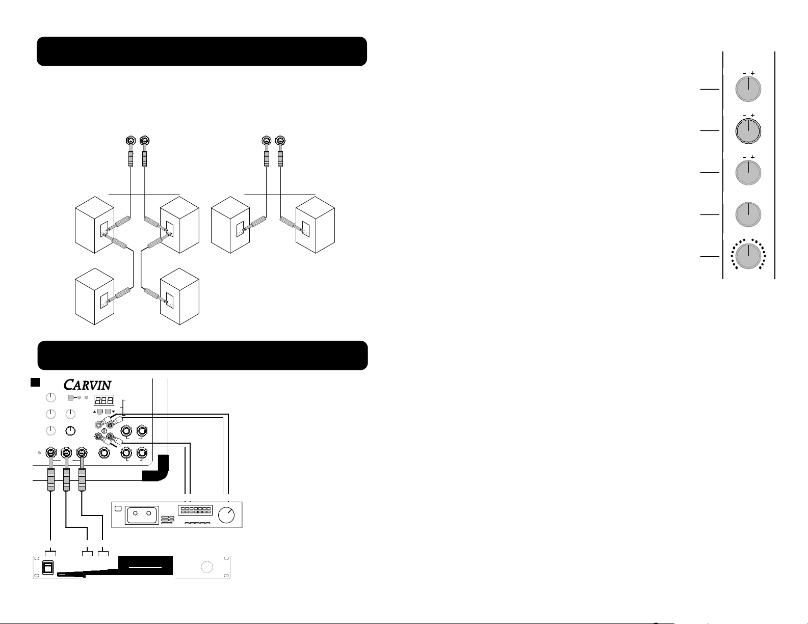
Here are two possible speaker connections, two or four 8 ohm speakers with
MADE
AUS
IN THE
RIGHT LEFT
SPEAKERS
4Ω
MINIMUM IMPEDANCE
4Ω
250 250 WATTS
8 OHM MINIMUM
8 OHM MINIMUM
8 OHM MINIMUM
8 OHM MINIMUM
4 OHM MINIMUM 4 OHM MINIMUM
MADE
AUS
IN THE
RIGHT LEFT
SPEAKERS
4Ω
MINIMUM IMPEDANCE
4Ω
250 250 WATTS
L/R MAIN
2
1
0 10
9
8
7
654
3
PHANTOM
2
1
0 10
9
8
7
654
3
MONITOR
2
1
0 10
9
8
7
654
3
DSP EFF RTN
2
1
0 10
9
8
7
654
3
EFF SEND
2
1
0 10
9
8
7
654
3
TAPE / EFF RTN
L
TAPE
RTN
TAPE
SEND
L R
L R
SEND L L R
MONITOREFFECTS
LINE OUT
R
127 EFFECTS
RRETURN
POWER
CX1252
AMP
PROTECT
AMP
PATCH
STEREO DSP
BYPASS 1
DELAYS 2-30
REVERB 31-90
CHORUS 91-110
FLANGE 111-128
TWO-TRACK
TAPE RECORDER
AUX EFFECTS PROCESSOR
MONO IN
L OUT R
TAPE OUT TAPE IN
6
7
8
9
10
PAN
0
MID
LOW
HI
0
3
6
9
12
3
6
9
12
0
3
6
9
12
3
6
9
12
0
3
6
9
12
3
6
9
12
L R
1
EFF /
REV54
3
2
1
0 10
9
8
7
6
one or one pair to each 1/4” speaker output. Also two 4 ohm speakers can be
connected one to each speaker output. Never go below 4 ohms on either of the
two speaker output jacks, this would result in premature distortion, thermal shut
down, and/or possible damage to the internal power amplifier.
15
SPEAKER CONNECTIONS
TAPE DECKS AND EXTERNAL EFFECTS
The basic hook up is simple,
using four (or two stereo)
RCA cables plug the TAPE
SEND on the mixer into the
tape deck’s inputs, and the
mixer’s TAPE RTN’s into the
tape deck’s outputs. With an
effects processor plug the
effects send 1/4”phone output
on the mixer into the input
jack on the effects processor,
and plug one or both (for
stereo) of the L/R EFFECTS
RETURN 1/4” phone inputs
on the mixer into the outputs
on the effects processor.
6. CHANNEL PAN CONTROL
The PAN control adjusts where the channel is heard in
the stereo field of the stereo main outputs. If it is turned
to the extreme left, then the channel will only be heard in
the left main output and similarly only in the right main
output if turned to the extreme right. In the center position the channel is heard equally in both the left and right
main outputs. A good starting point for the pan is in the
center position. Then if stereo placement is needed, a
quarter turn to the desired side from the center position
gives a smooth placement in the stereo field, or if desired
a full turn to one side gives a hard placement.
7. CHANNEL EFFECTS/REVERB LEVEL CONTROL
The EFF/REV control adjusts the volume of the channel
going to the effects send master control, and/or the internal DSP effects (if DSP is present). The effects control is
post channel level. This means adjustments in the channel’s EQ or level controls will be affecting the effects mix
output of that channel.
8-10. CHANNEL TONE CONTROLS
Each channel features three tone controls LO, MID, and HI. The LO and HI controls are shelving type tone controls with corner frequencies at 100Hz and
10KHz respectively. The shelving means, the for the LO control, all frequencies
from 100Hz down to the lowest frequency the mixer can handle are all boosted
when the knob is turned clockwise and cut when turned counter-clockwise from
the center position. For the HI control the shelving means all the frequencies
from 10kHz and up to the upper limit of the mixer are all boosted when the knob
is turned clockwise and cut when turned counter-clockwise from the center position. The MID control is a band pass type of tone control. The band pass
means a middle section of frequences centered around 1.5kHz, but not over
lapping the HI and LO controls, is boosted when the knob is turned clockwise
and cut when turned counter-clockwise from the center position.
Familarity with the channel tone controls:
The three tone controls can add brightness, clairity, and control to the channel’s
input signal. Here are some tonal references for these tone controls.
• LO affects the deep low bass tones and the typical bass tones.
• MID affects all the middle frequencies where the clairty of an average persons
spoken voice is mostly heard. Also the MID incompases the louder sometimes
harsher tones that can distort the over all sound of the system.
• HI affects the treble tones and very high treble tones bringing brightness and
brillance to the channel’s input.
Adjusting:
Use these controls to change the tonal shape of the input signal and in many
cases to reduce possible feedback from microphones near the mixer’s output
speakers. It is suggested the channel tone controls start out in their center
detent position where they do not effect the original incoming signal. Then, if
needed, turn the tone controls (boost,turn to the right, or cut, turn to the left) to
change the sound.
4
 Loading...